EP2604130B1 - Installation de transport pour le transport d'articles en forme de tige de l'industrie de traitement du tabac - Google Patents
Installation de transport pour le transport d'articles en forme de tige de l'industrie de traitement du tabac Download PDFInfo
- Publication number
- EP2604130B1 EP2604130B1 EP12195458.0A EP12195458A EP2604130B1 EP 2604130 B1 EP2604130 B1 EP 2604130B1 EP 12195458 A EP12195458 A EP 12195458A EP 2604130 B1 EP2604130 B1 EP 2604130B1
- Authority
- EP
- European Patent Office
- Prior art keywords
- head
- end guide
- conveyance
- rod
- conveying device
- Prior art date
- Legal status (The legal status is an assumption and is not a legal conclusion. Google has not performed a legal analysis and makes no representation as to the accuracy of the status listed.)
- Not-in-force
Links
- 241000208125 Nicotiana Species 0.000 title description 9
- 235000002637 Nicotiana tabacum Nutrition 0.000 title description 9
- 235000019504 cigarettes Nutrition 0.000 claims description 15
- 239000004033 plastic Substances 0.000 claims description 7
- 229920003023 plastic Polymers 0.000 claims description 7
- 230000001360 synchronised effect Effects 0.000 claims description 5
- 239000011248 coating agent Substances 0.000 claims description 2
- 238000000576 coating method Methods 0.000 claims description 2
- 239000002131 composite material Substances 0.000 claims description 2
- 239000000835 fiber Substances 0.000 claims 1
- 230000001737 promoting effect Effects 0.000 description 3
- 229920000049 Carbon (fiber) Polymers 0.000 description 2
- XEEYBQQBJWHFJM-UHFFFAOYSA-N Iron Chemical compound [Fe] XEEYBQQBJWHFJM-UHFFFAOYSA-N 0.000 description 2
- 230000000903 blocking effect Effects 0.000 description 2
- 239000004917 carbon fiber Substances 0.000 description 2
- 238000004519 manufacturing process Methods 0.000 description 2
- VNWKTOKETHGBQD-UHFFFAOYSA-N methane Chemical compound C VNWKTOKETHGBQD-UHFFFAOYSA-N 0.000 description 2
- 229920003229 poly(methyl methacrylate) Polymers 0.000 description 2
- 239000004417 polycarbonate Substances 0.000 description 2
- 239000004926 polymethyl methacrylate Substances 0.000 description 2
- 229920006448 PE-UHMW Polymers 0.000 description 1
- 229910000831 Steel Inorganic materials 0.000 description 1
- 230000006978 adaptation Effects 0.000 description 1
- 239000002216 antistatic agent Substances 0.000 description 1
- 239000003795 chemical substances by application Substances 0.000 description 1
- 235000019506 cigar Nutrition 0.000 description 1
- 238000010276 construction Methods 0.000 description 1
- 238000001514 detection method Methods 0.000 description 1
- 238000006073 displacement reaction Methods 0.000 description 1
- 235000013305 food Nutrition 0.000 description 1
- 229910052742 iron Inorganic materials 0.000 description 1
- 238000012806 monitoring device Methods 0.000 description 1
- 229920000515 polycarbonate Polymers 0.000 description 1
- 239000011208 reinforced composite material Substances 0.000 description 1
- 239000010959 steel Substances 0.000 description 1
- 238000004381 surface treatment Methods 0.000 description 1
- 230000007704 transition Effects 0.000 description 1
Images

Classifications
-
- A—HUMAN NECESSITIES
- A24—TOBACCO; CIGARS; CIGARETTES; SIMULATED SMOKING DEVICES; SMOKERS' REQUISITES
- A24C—MACHINES FOR MAKING CIGARS OR CIGARETTES
- A24C5/00—Making cigarettes; Making tipping materials for, or attaching filters or mouthpieces to, cigars or cigarettes
- A24C5/32—Separating, ordering, counting or examining cigarettes; Regulating the feeding of tobacco according to rod or cigarette condition
-
- A—HUMAN NECESSITIES
- A24—TOBACCO; CIGARS; CIGARETTES; SIMULATED SMOKING DEVICES; SMOKERS' REQUISITES
- A24C—MACHINES FOR MAKING CIGARS OR CIGARETTES
- A24C5/00—Making cigarettes; Making tipping materials for, or attaching filters or mouthpieces to, cigars or cigarettes
- A24C5/35—Adaptations of conveying apparatus for transporting cigarettes from making machine to packaging machine
-
- B—PERFORMING OPERATIONS; TRANSPORTING
- B65—CONVEYING; PACKING; STORING; HANDLING THIN OR FILAMENTARY MATERIAL
- B65G—TRANSPORT OR STORAGE DEVICES, e.g. CONVEYORS FOR LOADING OR TIPPING, SHOP CONVEYOR SYSTEMS OR PNEUMATIC TUBE CONVEYORS
- B65G11/00—Chutes
- B65G11/06—Chutes of helical or spiral form
- B65G11/063—Chutes of helical or spiral form for articles
Definitions
- the invention relates to a conveyor for, in particular vertical, conveying rod-shaped articles of the tobacco industry, in particular cigarettes or filter rods, wherein the conveyor has a conveyor channel, wherein the conveyor channel by two oppositely disposed and spaced apart side walls and by two oppositely disposed and spaced apart Kopfendenleit proposition is formed, wherein the side walls are arranged between the paired Kopfendenleit propositionn, wherein associated with promotion of rod-shaped articles in the conveying channel, the head ends of the rod-shaped articles each Kopfendenleitwand, and wherein in the conveying direction of the rod-shaped article, the delivery channel is helical.
- the invention relates to a conveyor system of the tobacco processing Industry with a conveyor for the promotion of an article mass flow of rod-shaped articles of the tobacco processing industry, in particular cigarettes or filter rods, wherein the rod-shaped articles are conveyed by means of the conveying means.
- rod-shaped articles of the tobacco processing industry in addition to filter rods, multi-segment filter rods or multifilament rods, e.g. Also understood cigarettes, cigarillos or cigars, with or without filters, to which the invention is equally applicable.
- these rod-shaped articles or parts thereof are conveyed via conveyors from a production machine to a further processing machine.
- filter rods via a conveyor channel and / or a conveyor shaft in mass flow to a storage magazine, such as a filter attachment machine, transported.
- DE 25 44 093 A1 discloses a conveyor for filter cigarettes.
- DE 2 310 291 A1 described as a conveyor for rod-shaped article a helical slide for transporting cigarettes.
- the slide has opposing side walls, which touch the outer layers of the cigarette in the cigarette ends.
- the object of the invention is that in a conveyor system of the tobacco processing industry in the vertical direction spaced apart terminal positions, which are to be bridged for a mass flow with rod-shaped articles, in a simple and flexible manner with each other connect, in particular at connection positions, which lie in different horizontal planes, wherein in the vertical transfer of the rod-shaped article from an upper connection position to a lower connection position, the orientation of the rod-shaped article is to be changed.
- a conveyor for, in particular vertical, conveying, preferably arranged in an article mass flow, rod-shaped articles of the tobacco industry, especially cigarettes or filter rods
- the conveyor has a conveyor channel, wherein the conveyor channel arranged by two opposite each other and from each other spaced side walls and is formed by two oppositely disposed and spaced Kopfendenleit phenomenon, wherein the side walls between the paired Kopfendenleit propositionn are arranged, wherein when conveying rod-shaped articles in the conveyor channel, the head ends of the rod-shaped articles are each associated with a Kopfendenleitwand, and wherein in the conveying direction rod-shaped article of the conveying channel is helically formed, which is further developed in that the distance between the mutually opposite Kopfendenleit walls in a conveying section of the conveying channel by means of a Kopfendenleitwandabstandseinstell sensible is adjustable.
- the invention is based on the idea that a helical conveying shaft or conveying channel is provided, which is easily adapted by means of Kopfendenleitwandabstandseinstell noticed to the (rod) length of the conveyed through the conveyor channel rod-shaped article, wherein during the promotion of the rod-shaped article through the helix-shaped, preferably vertically oriented, conveying channel the orientation of the rod-shaped article between the inlet side or inlet opening of the conveying channel and the outlet side or the outlet opening of the conveying channel is rotated by a predetermined angle.
- the side walls of the conveying channel are formed such that they rest against the outer layers of the mass flow of the rod-shaped article on both sides of the mass flow and contact the outer layers in the longitudinal axial direction and lead the outer layers of the conveyed through the conveying channel article mass flow.
- the width of the conveyor channel is set, which is provided in the invention that is adjusted by the movable head end guide the distance between the Kopfendenleit propositionn to the length of the promotional rod-shaped article.
- an article mass flow is understood as meaning a mass flow of rod-shaped articles stacked one above the other and next to one another in the conveying direction, such as filter rods, wherein the longitudinal axes of the rod-shaped articles in the densely packed package of the mass flow or in the hexagonal or hexagonal-like association during conveyance parallel to each other are aligned.
- the rod-shaped articles are preferably conveyed in the article mass flow in the transverse-axial direction, ie perpendicular to their longitudinal orientation.
- the height or width of an article mass flow, in particular transversely to the conveying direction is a multiple of the diameter of a single rod-shaped article.
- the side walls and the head end guide walls of the delivery channel are in one embodiment of electrostatically dissipative plastic, such as e.g. PC (polycarbonate), PMMA (polymethyl methacrylate) with appropriate surface treatments or carbon fiber reinforced composite such as e.g. PE-UHMW produced.
- PC polycarbonate
- PMMA polymethyl methacrylate
- the side walls as well as the Kopfendenleitance have antistatic agents to avoid electrostatic charges during the promotion of the rod-shaped article in the delivery channel.
- the plastics may be used in accordance with legal requirements, e.g. FDA and EU Plastics Directive approved for use in the food and pharmaceutical industries.
- the delivery channel is free of impact edges, i. formed without abutting edges to reduce the mechanical stress on the fragile rod-shaped articles during transport.
- the helical or helical conveying channel is designed in the conveying direction of the rod-shaped article depending on the requirements of the structural conditions and on a conveyor system dextrorotatory or anti-clockwise.
- the sections of the head end guide walls are displaced relative to one another, wherein the head end guide wall sections arranged opposite one another at the inlet opening and / or at the outlet opening of the conveying channel are arranged parallel to one another, so that the longitudinal axes of the rod-shaped articles to be conveyed are aligned at the inlet opening and at the outlet opening of the conveying channel perpendicular to the head end guide wall sections.
- the conveying channel has an inlet opening and an outlet opening in the conveying direction of the rod-shaped article, wherein at the inlet opening and at the outlet opening of the conveying channel, the mutually opposite end portions of the Kopfendenleitrank are arranged parallel to each other and wherein between the inlet opening and the outlet opening of the conveyor channel is helical or helical, so that when promoting the rod-shaped article in the conveyor channel the article at the outlet opening by a predetermined helix angle relative to the orientation of the rod-shaped Article are rotated at the inlet opening of the conveyor channel in position.
- the rod-shaped article are rotated about a vertically extending axis when conveying the rod-shaped article through an example vertically arranged conveyor channel in a downward conveying movement of the article mass flow rod-shaped article, whereby the rod-shaped article at the outlet or at the outlet opening of the conveyor channel to the helical angle of the conveyor channel are turned.
- a linearly movable actuator is arranged as an actuator at the inlet opening of the conveyor channel at the mutually opposite Kopfendenleit paragraphn, wherein the actuators at a predetermined angle less than 90 ° ( ⁇ 90 °) at the Kopfendenleit paragraphn are respectively arranged, wherein preferably the linear direction of movement of the actuators are parallel, preferably collinear, formed to each other.
- an actuator is also understood to mean a mechanically (actuatable) actuator.
- the conveyor is characterized in that arranged on a Kopfendenleitwand at the inlet opening linearly movable actuator and arranged on the same Kopfendenleitwand at the outlet opening linearly movable actuator for moving the Kopfendenleitwand are arranged, wherein the directions of movement of each other in the conveying direction spaced actuators, ie at the inlet opening and at the outlet opening of the conveyor channel, parallel to the same head end guide wall, and preferably in a plane perpendicular to the inlet opening or the outlet opening of the conveyor channel.
- an embodiment of the conveyor is characterized in that the Kopfendenleitwandabstandseinstell observed at least one or more, preferably motor driven drives as actuators as actuators for Kopfendenleitrise, in particular when using multiple drives for Kopfendenleitrise the drives coupled together, in particular synchronizable, are.
- a control device or a control unit for controlling the drives for automatically adjusting the distance of Kopfendenleitrise depending on a predetermined article format, in particular the article length provided.
- This control device is in one embodiment part of the Kopfendenleitwandabstandseinstell sensible, i. in that the head end guide wall distance adjusting device has a corresponding control device.
- the conveyor is designed as a module, wherein in particular using multiple, each designed as a module, in particular identically constructed, conveyors a helical conveying channel is formed for the rod-shaped article, the total angle of the conveyor channel the Spiral angle of the conveyors multiplied by the number of used, especially identical, modules corresponds.
- the conveyor is designed as a module with a helix angle of 15 ° or with a, in particular integer (> 1), multiples of 15 °.
- the modules have a predetermined module coil angle, e.g. of 15 ° or an integer multiple thereof, so that predetermined total helix angles can be formed in the vertical conveyance of the rod-shaped articles.
- the KopfendenleitN and / or the side walls of the conveyor are at least partially made of, preferably electrostatically dissipative and / or antistatic plastic and / or made of carbon fiber reinforced composite material and / or the KopfendenleitN and / or the side walls are provided with a, preferably electrostatically conductive surface coating.
- the KopfendenleitN and / or the side walls are formed electrostatically conductive.
- the handling of the conveyor is further improved in that at least one Kopfendenleitwand is designed as a pivotable Kopfendenleitwand the conveyor.
- a conveyor system of the tobacco-processing industry with a conveyor for promoting a mass flow of articles of rod-shaped articles of the tobacco industry, especially cigarettes or filter rods, the rod-shaped articles are conveyed by the conveyor and with a conveyor for, in particular vertical , Conveying the rod-shaped articles as described above.
- a conveyor system of the tobacco processing industry for the promotion of rod-shaped articles in the mass flow under the name RTS (Rod Transfer System) of Hauni Maschinenbau AG, Hamburg, known.
- a, preferably electronic, control device for controlling the, in particular electromotive, drives and / or the actuators is provided to change the distance between the Kopfendenleitprocessn, creating a simple and quick adjustment of the Kopfendenleit proposition at a Changing the length of the article to be promoted rod-shaped article is achieved.
- the distance of Kopfendenleitrise preferably automatically, to the predetermined length of the article be adjusted or adjusted.
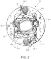
- FIG. 1 and 2 schematically is a plan view of a conveyor 10 according to the invention for the vertical conveying of arranged in the package association rod-shaped articles 12.1 shown in an article mass flow 12.
- Fig. 2 was omitted from the presentation of the article mass flow for reasons of clarity.
- the conveyor 10 has a helical or helical conveying channel 14, wherein the output from a delivery point of a feed conveyor article mass flow 12 is conveyed vertically downwards through the conveyor channel 14, so that the orientation of the article, eg cigarettes, with respect to their orientation at Entry into the delivery channel 14 is rotated.
- the angle of rotation between the orientation of the rod-shaped article at the inlet side or inlet opening of the conveying channel 14 and the orientation position of the rod-shaped article at the outlet side or outlet opening of the conveying channel 14 is also referred to as helix angle.
- the helix angle is 30 °, ie that the rod-shaped articles, such as filter cigarettes, after passing through the conveying channel 14 are rotated by 30 °.
- the delivery channel 14 is formed by two spaced side walls 16.1, 16.2 and two arranged on the end faces of the side walls 16.1, 16.2 Kopfendenleitance 18.1, 18.2.
- the Kopfendenleitnitro 18.1, 18.2 are arranged opposite the head ends of the rod-shaped article, wherein the movable Kopfendenleitance 18.1, 18.2 are arranged to be movable at an adjustable distance to each other.
- the side walls 16.1, 16.2 have the function that they on the lateral outer layers of the article mass flow 12 existing cigarettes (as rod-shaped products) lead in the lateral direction.
- the side walls 16.1, 16.2 are curved to form a helical or spiral conveyor channel in the conveying direction of the article mass flow.
- the Kopfendenleitance 18.1, 18.2 are also formed in the conveying direction of the article mass flow 12 with a curved surface, so that in cooperation of the curved in the conveying direction side walls 16.1, 16.2 with the Kopfendenleit propositionn 18.1, 18.2 a helical conveying channel 14 is formed in the vertical direction.
- the side walls 16.1, 16.2 are spaced apart at a predetermined distance on the inlet side and on the outlet side, whereby the width of the article mass flow 12 is determined.
- the side walls 16.1, 16.2 permanently fixed immovably fixed via at least one or more adjusting devices and / or at least one or more holding devices, for example on a frame or a support means for the conveyor 10, i. that the side walls 16.1, 16.2 are not changed in their position in the operation of the conveyor 10, but are simply performed manually adjustable, for example, in the case of adaptation due to changed connection machines in the mass flow.
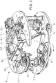
- Fig. 3 is a schematic perspective view of the conveyor according to the invention shown. How out Fig. 3 can be seen, in the region of the inlet side and the outlet side in each case a drive 20.1 and 20.2 connected to the Kopfendenleitwand 18.2 on the horizontally movable Kopfendenleitwand 18.2 (in the vertical conveying direction of the article mass flow).
- the drives 20.1, 20.2 are designed as actuators for the head end guide wall 18.2, which, when activated, move the head end guide wall 18.2 horizontally in its position as a linear drive. This causes a lifting movement of Kopfendenleitwand 18.2, wherein the Kopfendenleitwand 18.2 is moved in parallel, ie synchronized, actuation of the drives 20.1, 20.2 in the horizontal direction.
- the upper, input-side section of Kopfendenleitwand 18.2 is compared to the lower exit-side portion of the Kopfendenleitwand 18.2, which is connected to the drive 20.2, to the helix angle (here in the present case 30 °) rotated.
- movement directions of the drive 20.1 at the upper end of Kopfendenleitwand 18.2 and the lower, arranged on the outlet side drive 20.2 are arranged so that the directions of movement of the drives 20.1, 20.2 are aligned in a linear direction parallel to each other, so that when synchronized actuation of the drives 20.1, 20.2 a parallel stroke of Kopfendenleitwand 18.2 is executed.
- the upper drive 20.1 and the lower drive 20.2 are arranged at an angle of less than 90 °, in each case below 75 °, to the sections of the head end guide wall 18.2 at the inlet side and the outlet side of the conveyor channel 14.
- the Kopfendenleitwand 18.1 cooperating with the Kopfendenleitwand 18.2 has in the region of the inlet side of the conveyor channel 14 and on the outlet side of the conveyor channel 14 via respective drives 22.1 and 22.2, wherein the lower-side drive 22.2, in plan view in Fig. 2 is congruent with the upper drive 22.1, in Fig. 2 is not visible.
- the drives 20.1 and 20.2 for the Kopfendenleitwand 18.2 are each arranged on pivotable, crescent-shaped holding arms 21.1 and 22.2, wherein the holding arms 21.1, 21.2 are mounted about a vertical pivot axis 23.
- the Kopfendenleitwand 18.2 is formed pivotable.
- the Kopfendenleitwand 18.2 is pivoted away, so that the conveyor channel is accessible to a Kopfendenleitwandseite.
- the lower support arm 21.2 is sickle-shaped, wherein at the end facing away from the pivot axis 23 a nose-shaped projection 24 is formed, which is brought in the closed state of the conveyor channel 14 in engagement with a stop 25 for the support arm 21.2.
- the stop 25 may be formed with one or more magnets, whereby e.g. made of iron or steel holding arm 21.2 is held by the magnets of the stopper 25 in a closed position.
- a rotation angle detection device is provided, wherein in particular in a (not shown here) control device for the drives 20.1, 20.2 and 22.1, 22.2 of the rotation angle is determined.
- the displacement of Kopfendenleitance 18.1, 18.2 determined from the product of the pitch angle of the threaded rods of the drives 20.1, 20.2 and 22.1, 22.2, which are connected to the Kopfendenleit propositionn 18.1, 18.2, and the number of revolutions of the threaded rods.
- an end position monitoring device for detecting the end positions of the head end guide walls 18.1, 18.2 and / or the drives 20.1, 20.2 and 22.1, 22.2 is provided.
- an anti-lock device is provided for the drives 20.1, 20.2, 22.1 and 22.2, so that upon actuation of the drives 20.1, 20.2, 22.1 and 22.2 blocking of the drives, e.g. is detected after a predetermined period of time and the, preferably blocked or blocking, drives are disabled.
- dashed lines are the set positions of Kopfendenleitance 18.1, 18.2 drawn at shorter lengths of the rod-shaped article.
- the executed stroke length of the head end guide walls 18.1, 18.2 in the entry region and in the exit region is constant.
- drives or lifting drives for the Kopfendenleitance 18.1, 18.2 it is possible within the scope of the invention to provide appropriate belts, chains or electric motor or pneumatic individual drives or electromotive or pneumatic linear actuators.
- the drives for the Kopfendenleitance 18.1, 18.2 are also driven by hand.
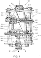
- FIG. 4 schematically another embodiment of a vertical conveyor 100 is shown in a side view, wherein the vertical conveyor 100 of three conveyors 10.1, 10.2, 10.3 is formed, which are interconnected as modules.
- each delivery module 10.1, 10.2, 10.3 each have a helix angle of 30 °, so that after passage of the article mass flow 12 at the bottom of the vertical conveyor 100, the rod-shaped article of the article mass flow 12 by 90 ° relative to their orientation on the inlet side of the conveying channel of the vertical conveyor 100th are turned.
- the exit side of the upper conveyor module is congruent with the head end guide walls on the inlet side of the subsequent conveyor module during the transition from a conveyor module to the following conveyor module.
Landscapes
- Framework For Endless Conveyors (AREA)
- Attitude Control For Articles On Conveyors (AREA)
- Manufacturing Of Cigar And Cigarette Tobacco (AREA)
Claims (14)
- Dispositif de transport (10) pour le transport, notamment vertical, d'articles en forme de tiges (12) de l'industrie du tabac, en particulier de cigarettes ou bâtons de filtre, le dispositif de transport (10) comportant un canal de transport (14), le canal de transport (14) étant constitué de deux parois latérales (16.1, 16.2) disposées en vis-à-vis et espacées l'une de l'autre et de deux parois de guidage d'extrémités de tête (18.1, 18.2) disposées en vis-à-vis et espacées l'une de l'autre, les parois latérales (16.1, 16.2) étant disposées entre les parois de guidage d'extrémités de tête (18.1, 18.2) disposées par paires, les extrémités de tête des articles en forme de tiges (12) étant respectivement associées à une paroi de guidage d'extrémités de tête (18.1, 18.2) lors du transport d'articles en forme de tiges (12) dans le canal de transport (14), et le canal de transport (14) étant réalisé en hélice dans la direction de transport des articles en forme de tiges (12), caractérisé en ce que la distance entre les parois de guidage d'extrémité de tête (18.1, 18.2) disposées en vis-à-vis est réglable dans la portion de transport du canal de transport (14) à l'aide d'un dispositif de réglage de distance entre parois de guidage d'extrémités de tête (20.1,20.2 ; 22.1, 22.2).
- Dispositif de transport (10) selon la revendication 1, caractérisé en ce que, lors de l'actionnement du dispositif de réglage de distance entre parois de guidage d'extrémités de tête (20.1, 20.2 ; 22.1, 22.2), les parois de guidage d'extrémités de tête (18.1, 18.2) disposées en vis-à-vis sont déplaçables ou sont déplacées, de préférence simultanément.
- Dispositif de transport (10) selon la revendication 1 ou 2, caractérisé en ce que, rapportée à la direction de transport des articles en forme de tiges (12) dans le canal de transport (14), dans une portion de transport du canal de transport, la distance entre les parois de guidage d'extrémités de tête (18.1, 18.2) disposées en vis-à-vis est réglable ou est réglée sur la longueur de la portion de canal de transport lors de l'actionnement du dispositif de réglage de distance entre parois de guidage d'extrémités de tête (20.1, 20.2 ; 22.1, 22.2).
- Dispositif de transport (10) selon l'une des revendications 1 à 3, caractérisé en ce que le canal de transport (14) présente une ouverture d'entrée et une ouverture de sortie dans la direction de transport des articles en forme de tiges (12), les parties d'extrémité, disposées en vis-à-vis, des parois de guidage d'extrémités de tête (18.1, 18.2) étant disposées de manière parallèle entre elles au niveau de l'orifice d'entrée et de l'orifice de sortie du canal de transport (14), et le canal de transport (14) étant agencé en hélice entre l'orifice d'entrée et l'orifice de sortie, de façon que, lors du transport des articles en forme de tiges (12) dans le canal de transport (14), les articles (12) soient tournés à l'ouverture de sortie, en ce qui concerne leur position, d'un angle d'hélice prédéterminé par rapport à l'orientation des articles en forme de tiges au niveau de l'ouverture d'entrée du canal de transport (14).
- Dispositif de transport (10) selon l'une des revendications 1 à 4, caractérisé en ce qu'au niveau de l'ouverture d'entrée du canal de transport (14), est disposé sur chacune des parois de guidage d'extrémités de tête disposées en vis-à-vis (18.1, 18.2) un actionneur déplaçable linéairement, les actionneurs étant disposés respectivement sur les parois de guidage d'extrémités de tête disposées en vis-à-vis (18.1, 18.2) en formant un angle prédéterminé inférieur à 90° (< 90°), les directions de mouvement linéaire des actionneurs étant, de préférence, mutuellement parallèles, de préférence colinéaires.
- Dispositif de transport (10) selon l'une des revendications 1 à 5, caractérisé en ce qu'au niveau de l'ouverture de sortie du canal de transport (14), est disposé sur chacune des parois de guidage d'extrémités de tête disposées en vis-à-vis (18.1, 18.2) un actionneur déplaçable linéairement, les actionneurs étant disposés respectivement sur les parois de guidage d'extrémités de tête disposées en vis-à-vis (18.1, 18.2) en formant un angle prédéterminé inférieur à 90° (< 90°), les directions de mouvement linéaire des actionneurs étant, de préférence, mutuellement parallèles, de préférence colinéaires.
- Dispositif de transport (10) selon l'une des revendications 1 à 6, caractérisé en ce que sont disposés un actionneur déplaçable linéairement situé sur une paroi de guidage d'extrémités de tête (18.1, 18.2) au niveau de l'ouverture d'entrée et un actionneur déplaçable linéairement situé sur la même paroi de guidage d'extrémités de tête (18.1, 18.2) au niveau de l'ouverture de sortie pour le mouvement de la paroi de guidage d'extrémités de tête (18 .1, 18.2), les directions de mouvement des actionneurs espacés l'un de l'autre dans la direction de transport sur la même paroi de guidage d'extrémités de tête (18.1, 18.2) étant parallèles et, de préférence, prévues dans un plan perpendiculaire à l'ouverture d'entrée ou à l'ouverture de sortie du canal de transport (14).
- Dispositif de transport (10) selon l'une des revendications 1 à 7, caractérisé en ce que le dispositif de réglage de distance entre parois de guidage d'extrémités de tête (20.1, 20.2 ; 22.1, 22.2) présente au moins un ou plusieurs entraînements, de préférence motorisés, en tant qu'actionneurs pour les parois de guidage d'extrémités de tête (18.1, 18.2), les entraînements étant couplés entre eux, en particulier pouvant être synchronisés, notamment en cas d'utilisation de plusieurs entraînements pour les parois de guidage d'extrémités de tête (18.1, 18.2).
- Dispositif de transport (10) selon l'une des revendications 1 à 8, caractérisé en ce que le dispositif de transport (10) est conçu en tant que module (10.1, 10.2, 10.3), un canal de transport (14) en hélice étant réalisé pour le transport des articles en forme de tiges notamment en utilisant plusieurs dispositifs de transport (10) conçus chacun en tant que module (10.1, 10.2, 10.3), en particulier de conception identique, l'angle d'hélice total du canal de transport (14) correspondant à l'angle d'hélice des dispositifs de transport (10) multiplié par le nombre de modules (10.1, 10.2, 10.3) utilisés, en particulier identiques.
- Dispositif de transport (10) selon l'une des revendications 1 à 9, caractérisé en ce que le dispositif de transport (10) est conçu en tant que module (10.1, 10.2, 10.3) avec un angle d'hélice de 15° ou un multiple, en particulier entier (> 1), de 15°.
- Dispositif de transport (10) selon l'une des revendications 1 à 10, caractérisé en ce que les parois de guidage d'extrémités de tête (18.1, 18.2) et/ou les parois latérales (16.1, 16.2) du dispositif de transport (10) sont réalisées au moins en partie en matière plastique, de préférence à dissipation électrostatique et/ou antistatique, et/ou en matériau composite renforcé de fibres de carbone et/ou en ce que les parois de guidage d'extrémités de tête (18.1, 18.2) et/ou les parois latérales (16.1, 16.2) sont pourvues d'un revêtement de surface conducteur.
- Dispositif de transport (10) selon l'une des revendications 1 à 11, caractérisé en ce qu'au moins une paroi de guidage d'extrémités de tête est conçue en tant que paroi de guidage pivotante du dispositif de transport (10).
- Installation de transport de l'industrie du tabac, comprenant un moyen de transport pour le transport d'un flux massique d'articles en forme de tiges (12) de l'industrie du tabac, en particulier des cigarettes ou bâtons de filtres, les articles en forme de tiges pouvant être transportés à l'aide du moyen de transport, et un dispositif de transport (10) destiné au transport, en particulier vertical, des articles en forme de tiges selon l'une des revendications 1 à 12.
- Installation de transport selon la revendication 13, caractérisée en ce qu'est prévu un dispositif de commande, de préférence électronique, pour la commande des entraînements, notamment par moteur électrique, et/ou des actionneurs pour modifier la distance entre les parois de guidage d'extrémités de tête.
Applications Claiming Priority (1)
| Application Number | Priority Date | Filing Date | Title |
|---|---|---|---|
| DE102011088357A DE102011088357A1 (de) | 2011-12-13 | 2011-12-13 | Fördereinrichtung zum Fördern von stabförmigen Artikeln der Tabak verarbeitenden Industrie |
Publications (3)
| Publication Number | Publication Date |
|---|---|
| EP2604130A2 EP2604130A2 (fr) | 2013-06-19 |
| EP2604130A3 EP2604130A3 (fr) | 2015-01-21 |
| EP2604130B1 true EP2604130B1 (fr) | 2016-04-27 |
Family
ID=47296983
Family Applications (1)
| Application Number | Title | Priority Date | Filing Date |
|---|---|---|---|
| EP12195458.0A Not-in-force EP2604130B1 (fr) | 2011-12-13 | 2012-12-04 | Installation de transport pour le transport d'articles en forme de tige de l'industrie de traitement du tabac |
Country Status (4)
| Country | Link |
|---|---|
| EP (1) | EP2604130B1 (fr) |
| CN (1) | CN103156274B (fr) |
| DE (1) | DE102011088357A1 (fr) |
| PL (1) | PL2604130T3 (fr) |
Families Citing this family (1)
| Publication number | Priority date | Publication date | Assignee | Title |
|---|---|---|---|---|
| DE102016107248A1 (de) * | 2016-04-19 | 2017-10-19 | Hauni Maschinenbau Gmbh | Behälter zum Aufnehmen oder Abgeben von Portionen eines aus stabförmigen Artikeln der Tabak verarbeitenden Industrie gebildeten Produktmassenstroms, sowie Anordnung zum Diskretisieren oder Bilden eines Produktmassenstroms mit solchen Behältern |
Family Cites Families (6)
| Publication number | Priority date | Publication date | Assignee | Title |
|---|---|---|---|---|
| GB1430061A (en) * | 1972-03-01 | 1976-03-31 | Molins Ltd | Feeding cigarettes |
| IT1047263B (it) | 1974-10-03 | 1980-09-10 | Molins Ltd | Perfezionamento agli apparecchi per trasportare sigarette e altri articoli con forma simile |
| DE19644335A1 (de) * | 1996-10-25 | 1998-04-30 | Focke & Co | Einrichtung zum Herstellen und Verpacken von Zigaretten |
| ITBO20030151A1 (it) * | 2003-03-20 | 2004-09-21 | Gd Spa | Unita' per l'alimentazione di filtri ad una macchina mettifiltro. |
| DE102005008337A1 (de) * | 2005-02-19 | 2006-08-31 | Hauni Maschinenbau Ag | Vorrichtung und Verfahren zum Transportieren stabförmiger Artikel |
| DE102006042238A1 (de) * | 2006-09-06 | 2008-03-27 | Hauni Maschinenbau Ag | Einrichtung zum Fördern von stabförmigen Artikeln |
-
2011
- 2011-12-13 DE DE102011088357A patent/DE102011088357A1/de not_active Ceased
-
2012
- 2012-12-04 PL PL12195458.0T patent/PL2604130T3/pl unknown
- 2012-12-04 EP EP12195458.0A patent/EP2604130B1/fr not_active Not-in-force
- 2012-12-13 CN CN201210538183.3A patent/CN103156274B/zh not_active Expired - Fee Related
Also Published As
| Publication number | Publication date |
|---|---|
| EP2604130A3 (fr) | 2015-01-21 |
| PL2604130T3 (pl) | 2016-11-30 |
| CN103156274A (zh) | 2013-06-19 |
| DE102011088357A1 (de) | 2013-06-13 |
| CN103156274B (zh) | 2017-03-01 |
| EP2604130A2 (fr) | 2013-06-19 |
Similar Documents
| Publication | Publication Date | Title |
|---|---|---|
| EP1989945B1 (fr) | Transport de charges d'articles en forme de tige de l'industrie de traitement du tabac | |
| DE102013202872B4 (de) | Verfahren und Vorrichtung zum Ausrichten und/oder Gruppieren von Artikeln, Stückgütern oder Gebinden | |
| EP1952705A2 (fr) | Cartouche de vidage et procédé de vidage de combles de puits remplis de produits en forme de tiges | |
| WO2013110427A1 (fr) | Dispositif et procédé destinés à retirer des produits, notamment des récipients tels que des bouteilles | |
| DE69609443T2 (de) | Variierbare Kapazitätspeicher für längliche Objekte | |
| EP1955604A1 (fr) | Dispositif et procédé destinés au remplissage de récipients à l'aide de produits en forme de tiges | |
| EP3162739B1 (fr) | Dispositif et procede de transfert de portions de saucisses | |
| EP3469911B1 (fr) | Dispositif de transport de saucisse oblongue comportant une courbure | |
| EP2478782B1 (fr) | Dispositif de transport pour produits en forme de tige de l'industrie de traitement du tabac | |
| EP1698554A1 (fr) | Tube d'alimentation pour comprimés | |
| EP2260732B1 (fr) | Dispositif et procédé de vidage successif de récipients remplis de produits en forme de tiges | |
| EP3802382B1 (fr) | Dispositif de transport et procédé de transport d'applicateurs de tampon | |
| EP2604130B1 (fr) | Installation de transport pour le transport d'articles en forme de tige de l'industrie de traitement du tabac | |
| EP1743856B1 (fr) | Dispositif et procédé de transport d'un courant d'articles et dispositif de remplissage d'un dispositif consécutif avec des articles en forme de tige | |
| DE102018124212A1 (de) | Förderstrecke für einen Transport einer Vielzahl von Artikeln und Verfahren zum Anpassen und/oder Betreiben einer Förderstrecke | |
| DE10317417B4 (de) | Vereinzelungs- und Fördervorrichtung | |
| EP1498369B1 (fr) | Dispositif de transport pour transporter d'objets suspendus sur des tringles | |
| WO2014177299A1 (fr) | Dispositif de transport pour le prélèvement de rouleaux de feuilles sur une machine à enrouler des feuilles | |
| EP1571106B1 (fr) | Transporteur à vis pour des cintres à vêtements | |
| EP2984009B1 (fr) | Dispositif de conservation limitée dans le temps d'objets | |
| EP3046842A1 (fr) | Dispositif de fabrication d'unités d'emballage | |
| EP2380831B1 (fr) | Dispositif destiné au transport et à l'isolation de barres de fumoir | |
| DE10051790A1 (de) | Behälter, Vorrichtung und Verfahren zum Transportieren von stabförmigen Artikeln der tabakverarbeitenden Industrie | |
| EP3135128A2 (fr) | Station de vidage de baquets destinée à vider des baquets remplis de produits en forme de tige et procédé pour vider des baquets remplis de produits en forme de tige à l'aide d'une station de vidage de baquets | |
| EP3045409B1 (fr) | Dispositif de retournement de marchandises au detail transportees en serie |
Legal Events
| Date | Code | Title | Description |
|---|---|---|---|
| PUAI | Public reference made under article 153(3) epc to a published international application that has entered the european phase |
Free format text: ORIGINAL CODE: 0009012 |
|
| 17P | Request for examination filed |
Effective date: 20121204 |
|
| AK | Designated contracting states |
Kind code of ref document: A2 Designated state(s): AL AT BE BG CH CY CZ DE DK EE ES FI FR GB GR HR HU IE IS IT LI LT LU LV MC MK MT NL NO PL PT RO RS SE SI SK SM TR |
|
| AX | Request for extension of the european patent |
Extension state: BA ME |
|
| PUAL | Search report despatched |
Free format text: ORIGINAL CODE: 0009013 |
|
| AK | Designated contracting states |
Kind code of ref document: A3 Designated state(s): AL AT BE BG CH CY CZ DE DK EE ES FI FR GB GR HR HU IE IS IT LI LT LU LV MC MK MT NL NO PL PT RO RS SE SI SK SM TR |
|
| AX | Request for extension of the european patent |
Extension state: BA ME |
|
| RIC1 | Information provided on ipc code assigned before grant |
Ipc: A24C 5/32 20060101AFI20141216BHEP Ipc: A24C 5/35 20060101ALI20141216BHEP Ipc: B65G 47/24 20060101ALI20141216BHEP |
|
| RBV | Designated contracting states (corrected) |
Designated state(s): AL AT BE BG CH CY CZ DE DK EE ES FI FR GB GR HR HU IE IS IT LI LT LU LV MC MK MT NL NO PL PT RO RS SE SI SK SM TR |
|
| GRAP | Despatch of communication of intention to grant a patent |
Free format text: ORIGINAL CODE: EPIDOSNIGR1 |
|
| RIC1 | Information provided on ipc code assigned before grant |
Ipc: A24C 5/32 20060101AFI20151113BHEP Ipc: B65G 11/06 20060101ALI20151113BHEP Ipc: A24C 5/35 20060101ALI20151113BHEP |
|
| INTG | Intention to grant announced |
Effective date: 20151209 |
|
| GRAS | Grant fee paid |
Free format text: ORIGINAL CODE: EPIDOSNIGR3 |
|
| GRAA | (expected) grant |
Free format text: ORIGINAL CODE: 0009210 |
|
| AK | Designated contracting states |
Kind code of ref document: B1 Designated state(s): AL AT BE BG CH CY CZ DE DK EE ES FI FR GB GR HR HU IE IS IT LI LT LU LV MC MK MT NL NO PL PT RO RS SE SI SK SM TR |
|
| REG | Reference to a national code |
Ref country code: GB Ref legal event code: FG4D Free format text: NOT ENGLISH |
|
| REG | Reference to a national code |
Ref country code: CH Ref legal event code: EP |
|
| REG | Reference to a national code |
Ref country code: AT Ref legal event code: REF Ref document number: 793736 Country of ref document: AT Kind code of ref document: T Effective date: 20160515 |
|
| REG | Reference to a national code |
Ref country code: IE Ref legal event code: FG4D Free format text: LANGUAGE OF EP DOCUMENT: GERMAN |
|
| REG | Reference to a national code |
Ref country code: DE Ref legal event code: R096 Ref document number: 502012006885 Country of ref document: DE |
|
| RAP2 | Party data changed (patent owner data changed or rights of a patent transferred) |
Owner name: HAUNI MASCHINENBAU GMBH |
|
| REG | Reference to a national code |
Ref country code: DE Ref legal event code: R081 Ref document number: 502012006885 Country of ref document: DE Owner name: HAUNI MASCHINENBAU GMBH, DE Free format text: FORMER OWNER: HAUNI MASCHINENBAU AG, 21033 HAMBURG, DE |
|
| REG | Reference to a national code |
Ref country code: NL Ref legal event code: FP |
|
| REG | Reference to a national code |
Ref country code: LT Ref legal event code: MG4D |
|
| REG | Reference to a national code |
Ref country code: NL Ref legal event code: PD Owner name: HAUNI MASCHINENBAU GMBH; DE Free format text: DETAILS ASSIGNMENT: VERANDERING VAN EIGENAAR(S), VERANDERING VAN DE JURIDISCHE ENTITEIT; FORMER OWNER NAME: HAUNI MASCHINENBAU AG Effective date: 20160809 |
|
| PG25 | Lapsed in a contracting state [announced via postgrant information from national office to epo] |
Ref country code: LT Free format text: LAPSE BECAUSE OF FAILURE TO SUBMIT A TRANSLATION OF THE DESCRIPTION OR TO PAY THE FEE WITHIN THE PRESCRIBED TIME-LIMIT Effective date: 20160427 Ref country code: NO Free format text: LAPSE BECAUSE OF FAILURE TO SUBMIT A TRANSLATION OF THE DESCRIPTION OR TO PAY THE FEE WITHIN THE PRESCRIBED TIME-LIMIT Effective date: 20160727 Ref country code: FI Free format text: LAPSE BECAUSE OF FAILURE TO SUBMIT A TRANSLATION OF THE DESCRIPTION OR TO PAY THE FEE WITHIN THE PRESCRIBED TIME-LIMIT Effective date: 20160427 |
|
| PG25 | Lapsed in a contracting state [announced via postgrant information from national office to epo] |
Ref country code: GR Free format text: LAPSE BECAUSE OF FAILURE TO SUBMIT A TRANSLATION OF THE DESCRIPTION OR TO PAY THE FEE WITHIN THE PRESCRIBED TIME-LIMIT Effective date: 20160728 Ref country code: ES Free format text: LAPSE BECAUSE OF FAILURE TO SUBMIT A TRANSLATION OF THE DESCRIPTION OR TO PAY THE FEE WITHIN THE PRESCRIBED TIME-LIMIT Effective date: 20160427 Ref country code: PT Free format text: LAPSE BECAUSE OF FAILURE TO SUBMIT A TRANSLATION OF THE DESCRIPTION OR TO PAY THE FEE WITHIN THE PRESCRIBED TIME-LIMIT Effective date: 20160829 Ref country code: LV Free format text: LAPSE BECAUSE OF FAILURE TO SUBMIT A TRANSLATION OF THE DESCRIPTION OR TO PAY THE FEE WITHIN THE PRESCRIBED TIME-LIMIT Effective date: 20160427 Ref country code: RS Free format text: LAPSE BECAUSE OF FAILURE TO SUBMIT A TRANSLATION OF THE DESCRIPTION OR TO PAY THE FEE WITHIN THE PRESCRIBED TIME-LIMIT Effective date: 20160427 Ref country code: SE Free format text: LAPSE BECAUSE OF FAILURE TO SUBMIT A TRANSLATION OF THE DESCRIPTION OR TO PAY THE FEE WITHIN THE PRESCRIBED TIME-LIMIT Effective date: 20160427 Ref country code: HR Free format text: LAPSE BECAUSE OF FAILURE TO SUBMIT A TRANSLATION OF THE DESCRIPTION OR TO PAY THE FEE WITHIN THE PRESCRIBED TIME-LIMIT Effective date: 20160427 |
|
| REG | Reference to a national code |
Ref country code: DE Ref legal event code: R097 Ref document number: 502012006885 Country of ref document: DE |
|
| PG25 | Lapsed in a contracting state [announced via postgrant information from national office to epo] |
Ref country code: DK Free format text: LAPSE BECAUSE OF FAILURE TO SUBMIT A TRANSLATION OF THE DESCRIPTION OR TO PAY THE FEE WITHIN THE PRESCRIBED TIME-LIMIT Effective date: 20160427 Ref country code: SK Free format text: LAPSE BECAUSE OF FAILURE TO SUBMIT A TRANSLATION OF THE DESCRIPTION OR TO PAY THE FEE WITHIN THE PRESCRIBED TIME-LIMIT Effective date: 20160427 Ref country code: EE Free format text: LAPSE BECAUSE OF FAILURE TO SUBMIT A TRANSLATION OF THE DESCRIPTION OR TO PAY THE FEE WITHIN THE PRESCRIBED TIME-LIMIT Effective date: 20160427 Ref country code: RO Free format text: LAPSE BECAUSE OF FAILURE TO SUBMIT A TRANSLATION OF THE DESCRIPTION OR TO PAY THE FEE WITHIN THE PRESCRIBED TIME-LIMIT Effective date: 20160427 Ref country code: CZ Free format text: LAPSE BECAUSE OF FAILURE TO SUBMIT A TRANSLATION OF THE DESCRIPTION OR TO PAY THE FEE WITHIN THE PRESCRIBED TIME-LIMIT Effective date: 20160427 |
|
| PG25 | Lapsed in a contracting state [announced via postgrant information from national office to epo] |
Ref country code: SM Free format text: LAPSE BECAUSE OF FAILURE TO SUBMIT A TRANSLATION OF THE DESCRIPTION OR TO PAY THE FEE WITHIN THE PRESCRIBED TIME-LIMIT Effective date: 20160427 |
|
| PLBE | No opposition filed within time limit |
Free format text: ORIGINAL CODE: 0009261 |
|
| STAA | Information on the status of an ep patent application or granted ep patent |
Free format text: STATUS: NO OPPOSITION FILED WITHIN TIME LIMIT |
|
| 26N | No opposition filed |
Effective date: 20170130 |
|
| PG25 | Lapsed in a contracting state [announced via postgrant information from national office to epo] |
Ref country code: BE Free format text: LAPSE BECAUSE OF NON-PAYMENT OF DUE FEES Effective date: 20161231 Ref country code: SI Free format text: LAPSE BECAUSE OF FAILURE TO SUBMIT A TRANSLATION OF THE DESCRIPTION OR TO PAY THE FEE WITHIN THE PRESCRIBED TIME-LIMIT Effective date: 20160427 |
|
| REG | Reference to a national code |
Ref country code: CH Ref legal event code: PL |
|
| GBPC | Gb: european patent ceased through non-payment of renewal fee |
Effective date: 20161204 |
|
| PG25 | Lapsed in a contracting state [announced via postgrant information from national office to epo] |
Ref country code: MC Free format text: LAPSE BECAUSE OF FAILURE TO SUBMIT A TRANSLATION OF THE DESCRIPTION OR TO PAY THE FEE WITHIN THE PRESCRIBED TIME-LIMIT Effective date: 20160427 |
|
| REG | Reference to a national code |
Ref country code: FR Ref legal event code: ST Effective date: 20170831 |
|
| REG | Reference to a national code |
Ref country code: IE Ref legal event code: MM4A |
|
| PG25 | Lapsed in a contracting state [announced via postgrant information from national office to epo] |
Ref country code: LI Free format text: LAPSE BECAUSE OF NON-PAYMENT OF DUE FEES Effective date: 20161231 Ref country code: LU Free format text: LAPSE BECAUSE OF NON-PAYMENT OF DUE FEES Effective date: 20161204 Ref country code: CH Free format text: LAPSE BECAUSE OF NON-PAYMENT OF DUE FEES Effective date: 20161231 Ref country code: FR Free format text: LAPSE BECAUSE OF NON-PAYMENT OF DUE FEES Effective date: 20170102 |
|
| PG25 | Lapsed in a contracting state [announced via postgrant information from national office to epo] |
Ref country code: IE Free format text: LAPSE BECAUSE OF NON-PAYMENT OF DUE FEES Effective date: 20161204 Ref country code: GB Free format text: LAPSE BECAUSE OF NON-PAYMENT OF DUE FEES Effective date: 20161204 |
|
| REG | Reference to a national code |
Ref country code: BE Ref legal event code: MM Effective date: 20161231 |
|
| PG25 | Lapsed in a contracting state [announced via postgrant information from national office to epo] |
Ref country code: HU Free format text: LAPSE BECAUSE OF FAILURE TO SUBMIT A TRANSLATION OF THE DESCRIPTION OR TO PAY THE FEE WITHIN THE PRESCRIBED TIME-LIMIT; INVALID AB INITIO Effective date: 20121204 Ref country code: CY Free format text: LAPSE BECAUSE OF FAILURE TO SUBMIT A TRANSLATION OF THE DESCRIPTION OR TO PAY THE FEE WITHIN THE PRESCRIBED TIME-LIMIT Effective date: 20160427 |
|
| PG25 | Lapsed in a contracting state [announced via postgrant information from national office to epo] |
Ref country code: MK Free format text: LAPSE BECAUSE OF FAILURE TO SUBMIT A TRANSLATION OF THE DESCRIPTION OR TO PAY THE FEE WITHIN THE PRESCRIBED TIME-LIMIT Effective date: 20160427 Ref country code: IS Free format text: LAPSE BECAUSE OF FAILURE TO SUBMIT A TRANSLATION OF THE DESCRIPTION OR TO PAY THE FEE WITHIN THE PRESCRIBED TIME-LIMIT Effective date: 20160427 Ref country code: TR Free format text: LAPSE BECAUSE OF FAILURE TO SUBMIT A TRANSLATION OF THE DESCRIPTION OR TO PAY THE FEE WITHIN THE PRESCRIBED TIME-LIMIT Effective date: 20160427 |
|
| PG25 | Lapsed in a contracting state [announced via postgrant information from national office to epo] |
Ref country code: BG Free format text: LAPSE BECAUSE OF FAILURE TO SUBMIT A TRANSLATION OF THE DESCRIPTION OR TO PAY THE FEE WITHIN THE PRESCRIBED TIME-LIMIT Effective date: 20160427 |
|
| PG25 | Lapsed in a contracting state [announced via postgrant information from national office to epo] |
Ref country code: MT Free format text: LAPSE BECAUSE OF FAILURE TO SUBMIT A TRANSLATION OF THE DESCRIPTION OR TO PAY THE FEE WITHIN THE PRESCRIBED TIME-LIMIT Effective date: 20160427 |
|
| PG25 | Lapsed in a contracting state [announced via postgrant information from national office to epo] |
Ref country code: AL Free format text: LAPSE BECAUSE OF FAILURE TO SUBMIT A TRANSLATION OF THE DESCRIPTION OR TO PAY THE FEE WITHIN THE PRESCRIBED TIME-LIMIT Effective date: 20160427 |
|
| REG | Reference to a national code |
Ref country code: AT Ref legal event code: MM01 Ref document number: 793736 Country of ref document: AT Kind code of ref document: T Effective date: 20171204 |
|
| PG25 | Lapsed in a contracting state [announced via postgrant information from national office to epo] |
Ref country code: AT Free format text: LAPSE BECAUSE OF NON-PAYMENT OF DUE FEES Effective date: 20171204 |
|
| PGFP | Annual fee paid to national office [announced via postgrant information from national office to epo] |
Ref country code: NL Payment date: 20191220 Year of fee payment: 8 |
|
| PGFP | Annual fee paid to national office [announced via postgrant information from national office to epo] |
Ref country code: PL Payment date: 20191125 Year of fee payment: 8 Ref country code: IT Payment date: 20191231 Year of fee payment: 8 |
|
| PGFP | Annual fee paid to national office [announced via postgrant information from national office to epo] |
Ref country code: DE Payment date: 20200102 Year of fee payment: 8 |
|
| REG | Reference to a national code |
Ref country code: DE Ref legal event code: R119 Ref document number: 502012006885 Country of ref document: DE |
|
| REG | Reference to a national code |
Ref country code: NL Ref legal event code: MM Effective date: 20210101 |
|
| PG25 | Lapsed in a contracting state [announced via postgrant information from national office to epo] |
Ref country code: NL Free format text: LAPSE BECAUSE OF NON-PAYMENT OF DUE FEES Effective date: 20210101 |
|
| PG25 | Lapsed in a contracting state [announced via postgrant information from national office to epo] |
Ref country code: IT Free format text: LAPSE BECAUSE OF NON-PAYMENT OF DUE FEES Effective date: 20201204 |
|
| PG25 | Lapsed in a contracting state [announced via postgrant information from national office to epo] |
Ref country code: DE Free format text: LAPSE BECAUSE OF NON-PAYMENT OF DUE FEES Effective date: 20210701 |
|
| PG25 | Lapsed in a contracting state [announced via postgrant information from national office to epo] |
Ref country code: PL Free format text: LAPSE BECAUSE OF NON-PAYMENT OF DUE FEES Effective date: 20201204 |