EP2604094B1 - Optoelectronic device, system and method for obtaining an ambient light spectrum and modifying an emitted light - Google Patents
Optoelectronic device, system and method for obtaining an ambient light spectrum and modifying an emitted light Download PDFInfo
- Publication number
- EP2604094B1 EP2604094B1 EP11700007.5A EP11700007A EP2604094B1 EP 2604094 B1 EP2604094 B1 EP 2604094B1 EP 11700007 A EP11700007 A EP 11700007A EP 2604094 B1 EP2604094 B1 EP 2604094B1
- Authority
- EP
- European Patent Office
- Prior art keywords
- light
- optoelectronic device
- spectrum
- parameter
- modifying
- Prior art date
- Legal status (The legal status is an assumption and is not a legal conclusion. Google has not performed a legal analysis and makes no representation as to the accuracy of the status listed.)
- Not-in-force
Links
- 230000005693 optoelectronics Effects 0.000 title claims description 121
- 238000001228 spectrum Methods 0.000 title claims description 118
- 238000000034 method Methods 0.000 title claims description 29
- 230000007613 environmental effect Effects 0.000 claims description 47
- 230000003595 spectral effect Effects 0.000 claims description 34
- 230000003287 optical effect Effects 0.000 claims description 25
- 238000013528 artificial neural network Methods 0.000 claims description 12
- 238000005516 engineering process Methods 0.000 claims description 10
- 230000004907 flux Effects 0.000 claims description 9
- 239000013307 optical fiber Substances 0.000 claims description 8
- 239000006185 dispersion Substances 0.000 claims 1
- 230000008859 change Effects 0.000 description 26
- 238000004891 communication Methods 0.000 description 20
- 230000000875 corresponding effect Effects 0.000 description 19
- 230000009471 action Effects 0.000 description 9
- 230000008569 process Effects 0.000 description 9
- 230000008878 coupling Effects 0.000 description 8
- 238000010168 coupling process Methods 0.000 description 8
- 238000005859 coupling reaction Methods 0.000 description 8
- 238000012545 processing Methods 0.000 description 7
- 230000004044 response Effects 0.000 description 7
- 238000003860 storage Methods 0.000 description 7
- 238000004422 calculation algorithm Methods 0.000 description 6
- 238000004590 computer program Methods 0.000 description 6
- 238000001514 detection method Methods 0.000 description 6
- 239000000758 substrate Substances 0.000 description 5
- 238000006243 chemical reaction Methods 0.000 description 4
- 238000009826 distribution Methods 0.000 description 4
- 239000003086 colorant Substances 0.000 description 3
- 230000001276 controlling effect Effects 0.000 description 3
- 230000006870 function Effects 0.000 description 3
- 238000005286 illumination Methods 0.000 description 3
- 230000002452 interceptive effect Effects 0.000 description 3
- 230000033001 locomotion Effects 0.000 description 3
- 239000004065 semiconductor Substances 0.000 description 3
- 230000003068 static effect Effects 0.000 description 3
- 238000013459 approach Methods 0.000 description 2
- 210000004027 cell Anatomy 0.000 description 2
- 238000005094 computer simulation Methods 0.000 description 2
- 230000000694 effects Effects 0.000 description 2
- 238000005538 encapsulation Methods 0.000 description 2
- 239000000835 fiber Substances 0.000 description 2
- 230000014509 gene expression Effects 0.000 description 2
- 230000010354 integration Effects 0.000 description 2
- 230000003993 interaction Effects 0.000 description 2
- 230000000670 limiting effect Effects 0.000 description 2
- 239000000463 material Substances 0.000 description 2
- 210000002569 neuron Anatomy 0.000 description 2
- 238000003909 pattern recognition Methods 0.000 description 2
- 238000009877 rendering Methods 0.000 description 2
- 229910052710 silicon Inorganic materials 0.000 description 2
- 239000010703 silicon Substances 0.000 description 2
- PQHZWWBJPCNNGI-UHFFFAOYSA-N 1,3,5-trichloro-2-(2,5-dichlorophenyl)benzene Chemical compound ClC1=CC=C(Cl)C(C=2C(=CC(Cl)=CC=2Cl)Cl)=C1 PQHZWWBJPCNNGI-UHFFFAOYSA-N 0.000 description 1
- 241001465754 Metazoa Species 0.000 description 1
- OAICVXFJPJFONN-UHFFFAOYSA-N Phosphorus Chemical compound [P] OAICVXFJPJFONN-UHFFFAOYSA-N 0.000 description 1
- 230000006978 adaptation Effects 0.000 description 1
- 238000003491 array Methods 0.000 description 1
- 238000013529 biological neural network Methods 0.000 description 1
- 230000005540 biological transmission Effects 0.000 description 1
- 230000004397 blinking Effects 0.000 description 1
- 239000003990 capacitor Substances 0.000 description 1
- 230000000295 complement effect Effects 0.000 description 1
- 230000002596 correlated effect Effects 0.000 description 1
- 230000003247 decreasing effect Effects 0.000 description 1
- 238000010894 electron beam technology Methods 0.000 description 1
- 230000002996 emotional effect Effects 0.000 description 1
- 238000005265 energy consumption Methods 0.000 description 1
- 238000001914 filtration Methods 0.000 description 1
- 239000011521 glass Substances 0.000 description 1
- 230000010365 information processing Effects 0.000 description 1
- 238000009434 installation Methods 0.000 description 1
- 238000001459 lithography Methods 0.000 description 1
- 238000013178 mathematical model Methods 0.000 description 1
- 238000012544 monitoring process Methods 0.000 description 1
- 230000001537 neural effect Effects 0.000 description 1
- 238000005457 optimization Methods 0.000 description 1
- 238000004806 packaging method and process Methods 0.000 description 1
- 230000000803 paradoxical effect Effects 0.000 description 1
- 238000000206 photolithography Methods 0.000 description 1
- 239000002096 quantum dot Substances 0.000 description 1
- 239000010453 quartz Substances 0.000 description 1
- 230000005855 radiation Effects 0.000 description 1
- 230000010076 replication Effects 0.000 description 1
- 230000035945 sensitivity Effects 0.000 description 1
- VYPSYNLAJGMNEJ-UHFFFAOYSA-N silicon dioxide Inorganic materials O=[Si]=O VYPSYNLAJGMNEJ-UHFFFAOYSA-N 0.000 description 1
- 239000007787 solid Substances 0.000 description 1
- 230000036962 time dependent Effects 0.000 description 1
- 230000001960 triggered effect Effects 0.000 description 1
Images
Classifications
-
- H—ELECTRICITY
- H05—ELECTRIC TECHNIQUES NOT OTHERWISE PROVIDED FOR
- H05B—ELECTRIC HEATING; ELECTRIC LIGHT SOURCES NOT OTHERWISE PROVIDED FOR; CIRCUIT ARRANGEMENTS FOR ELECTRIC LIGHT SOURCES, IN GENERAL
- H05B47/00—Circuit arrangements for operating light sources in general, i.e. where the type of light source is not relevant
- H05B47/10—Controlling the light source
- H05B47/105—Controlling the light source in response to determined parameters
- H05B47/11—Controlling the light source in response to determined parameters by determining the brightness or colour temperature of ambient light
-
- H—ELECTRICITY
- H05—ELECTRIC TECHNIQUES NOT OTHERWISE PROVIDED FOR
- H05B—ELECTRIC HEATING; ELECTRIC LIGHT SOURCES NOT OTHERWISE PROVIDED FOR; CIRCUIT ARRANGEMENTS FOR ELECTRIC LIGHT SOURCES, IN GENERAL
- H05B45/00—Circuit arrangements for operating light-emitting diodes [LED]
- H05B45/10—Controlling the intensity of the light
- H05B45/18—Controlling the intensity of the light using temperature feedback
-
- H—ELECTRICITY
- H05—ELECTRIC TECHNIQUES NOT OTHERWISE PROVIDED FOR
- H05B—ELECTRIC HEATING; ELECTRIC LIGHT SOURCES NOT OTHERWISE PROVIDED FOR; CIRCUIT ARRANGEMENTS FOR ELECTRIC LIGHT SOURCES, IN GENERAL
- H05B45/00—Circuit arrangements for operating light-emitting diodes [LED]
- H05B45/20—Controlling the colour of the light
-
- H—ELECTRICITY
- H05—ELECTRIC TECHNIQUES NOT OTHERWISE PROVIDED FOR
- H05B—ELECTRIC HEATING; ELECTRIC LIGHT SOURCES NOT OTHERWISE PROVIDED FOR; CIRCUIT ARRANGEMENTS FOR ELECTRIC LIGHT SOURCES, IN GENERAL
- H05B47/00—Circuit arrangements for operating light sources in general, i.e. where the type of light source is not relevant
- H05B47/10—Controlling the light source
- H05B47/105—Controlling the light source in response to determined parameters
- H05B47/115—Controlling the light source in response to determined parameters by determining the presence or movement of objects or living beings
-
- H—ELECTRICITY
- H05—ELECTRIC TECHNIQUES NOT OTHERWISE PROVIDED FOR
- H05B—ELECTRIC HEATING; ELECTRIC LIGHT SOURCES NOT OTHERWISE PROVIDED FOR; CIRCUIT ARRANGEMENTS FOR ELECTRIC LIGHT SOURCES, IN GENERAL
- H05B47/00—Circuit arrangements for operating light sources in general, i.e. where the type of light source is not relevant
- H05B47/10—Controlling the light source
- H05B47/165—Controlling the light source following a pre-assigned programmed sequence; Logic control [LC]
-
- Y—GENERAL TAGGING OF NEW TECHNOLOGICAL DEVELOPMENTS; GENERAL TAGGING OF CROSS-SECTIONAL TECHNOLOGIES SPANNING OVER SEVERAL SECTIONS OF THE IPC; TECHNICAL SUBJECTS COVERED BY FORMER USPC CROSS-REFERENCE ART COLLECTIONS [XRACs] AND DIGESTS
- Y02—TECHNOLOGIES OR APPLICATIONS FOR MITIGATION OR ADAPTATION AGAINST CLIMATE CHANGE
- Y02B—CLIMATE CHANGE MITIGATION TECHNOLOGIES RELATED TO BUILDINGS, e.g. HOUSING, HOUSE APPLIANCES OR RELATED END-USER APPLICATIONS
- Y02B20/00—Energy efficient lighting technologies, e.g. halogen lamps or gas discharge lamps
- Y02B20/40—Control techniques providing energy savings, e.g. smart controller or presence detection
Definitions
- the present invention relates to an optoelectronic device for obtaining an ambient light spectrum and controlling an emitted light, and a system for modifying an emitted light.
- the invention also relates to a method for modifying an emitted light, a computer program product comprising instructions to perform said method, a reflective device for determining the calibration of an optoelectronic device, and a method for determining the calibration of an optoelectronic device.
- lighting apparatus that include light sensors and light sources, the light sensors being focused to obtain properties (e.g. color coordinates or light levels) of the light emitted by the light sources for adjusting or calibrating said emitted light in order to finally match it to a given reference value.
- properties e.g. color coordinates or light levels
- light sensors integrating light sensors and light sources
- said light sensors being used for detecting presence (of people, for example) and adapting the intensity of the light emitted by the light sources according to the result of said detection.
- the intensity of the light is decreased in case of not detecting presence with the objective of saving electric energy.
- the US patent application US 2010/0007491 A1 describes an integrated image recognition and spectral detection device particularly suitable for monitoring settings of a light.
- the application also describes how to automatically control the settings of a light through image recognition and spectral detection of the light exiting the same lighting device, particularly how to automatically control changes in the color properties of the light in response to the image recognition.
- the device comprises an image sensor array for recognizing images and motion, and a light filtering structure, that may be for example a Fabry-Perot resonator structure or an array of cut filtered glass, for detecting spectral components of received light.
- the above mentioned lighting devices present some drawbacks related to the fact that they modify the emission of their light output by using either a pre-stored spectral parameter or a measure of a light property which is inaccurate for certain applications, due to the fact that they use filters or other structures, that are not accurate enough for obtaining detailed spectral properties of light.
- said lighting devices are not suitable for use in interactive lighting environments where spectral changes occur as a consequence of multiple reflections caused by, for example, moving objects found in the environment where the device is placed or changes in daylight conditions of the environment, and also, they are not able to react to said spectrum changes accordingly in real time.
- WO 2008/012715 A2 discloses an integrated image recognition and spectral detection device which allows a sophisticated automatic control of the settings of a light.
- a device and method for measuring ambient spectra and modifying a light spectrum of an emitted light is provided which, depending on an obtained light spectrum from an environmental light by means of a miniaturized spectrometer, is able to detect changes on the environmental light spectrum within an area in real time, in an optimum way.
- an optoelectronic device is provided according to claim 1.
- an optimum control of the light reflected on an environment is achieved, which is able to detect any changes in the environmental illumination through its spectral characteristics, and change the light properties of an emitted light in a desired way.
- the area of the environment which is illuminated by the plurality of light emitters when they are lit, and which reflects light towards the spectrometer may additionally be illuminated by further light sources, and therefore, the changes in the environmental light may also take into account other lights (being artificial, natural, or reflections of nearby objects or people) which are adjacent or placed near the optoelectronic device.
- CMOS Complementary metal-oxide-semiconductor
- CMOS technology is used in microprocessors, micro controllers, static RAM, and other digital logic circuits.
- CMOS technology is also used for several analog circuits such as image sensors, data converters, and highly integrated transceivers for many types of communication. Therefore, by a CMOS-based spectrometer, it should be understood a spectrometer that has been fabricated by using technological processes that are commonly utilized in a CMOS facility or foundry. In this sense, it is worth mentioning that the optical dispersive element (grating) and the light or image sensor that are comprised in the spectrometer can be fabricated using a variety of techniques that exist within the CMOS technology.
- the dispersive element could be made by optical lithography, but also by other more advanced processes such as nanoimprinting.
- the nanoimprinting method makes use of a stamp material, typically silicon or quartz, with a pattern produced by electron-beam (e-beam) lithography.
- the stamp is then physically pressed against a substrate coated with a UV-curable low-viscosity resist, thus transferring the desired circuit pattern to the substrate in a one-shot process.
- the substrate is hardened by shining UV light through it.
- the stamp is removed, leaving a three-dimensional imprint of the circuit in place on the substrate.
- This ability to apply a 3D pattern to a substrate in a single process is ideal for integration of optical gratings in CMOS technology.
- CMOS sensors and CCD sensors (closely spaced array of gated MOS capacitors on a continuous dielectric covering the semiconductor surface), but other light detection systems exist that are CMOS-compatible and can be potentially used.
- the means for modifying the light emitted by the light emitters may be comprised in a computing controller, such as a micro-controller, a microprocessor, a Digital signal processor (DSP), a Field programmable gate array (FPGA), or any other electronic block suitable for controlling the interaction between the spectrometer signal and the light emitters.
- a computing controller such as a micro-controller, a microprocessor, a Digital signal processor (DSP), a Field programmable gate array (FPGA), or any other electronic block suitable for controlling the interaction between the spectrometer signal and the light emitters.
- said computing controller may comprise the electronics needed to adapt the signals provided by the spectrometer, and may further comprise a driving electronics to provide power to the light emitters.
- the computing controller and the electronic drivers may also comprise means for individually controlling the output of each light emitter of the optoelectronic device, by means of techniques such as Amplitude modulation (AM) or Pulse Width Modulation (PWM) or other known techniques, enabling the light emitters to emit a specific light with a specific spectral content, related to the obtained light spectrum.
- AM Amplitude modulation
- PWM Pulse Width Modulation
- the relationship between the obtained light spectrum and the emitted light may involve mathematical expressions of different degree of complexity.
- the easiest relationship is a linear response between the obtained spectrum and the spectrum of the emitted light, but other more sophisticated relationships can be established.
- highly non-linear relations are possible in light switching applications as a function of a parameter of the obtained light spectrum.
- LER luminous efficacy of radiation
- the optoelectronic device may be fixed on a surface of an area, such as a ceiling of a room or wide area, or it may also be embodied as a portable handheld device, in such a way that it can be used in any location, transporting it from one place to another and placing it wherever necessary.
- the spectrometer comprises a light inlet to obtain the light spectrum of the environmental light.
- the device comprises at least one optical element coupled to the light inlet, for increasing the incoming light flux through the light inlet.
- the optical element coupled to the light inlet the solid angle of light collection of said light inlet is increased, thus obtaining a larger amount of environmental light. Therefore, the obtained light spectrum of the environmental light from a given area is more precise, since the signal-to-noise ratio is increased.
- the optical element comprises an optical lens set.
- An appropriately designed optical lens or set of lenses may highly improve the coupled flux of ambient light from the environment which, given the low light sensibility of the present-day miniaturized spectrometers, is difficult to obtain, specially if the light intensity of an environment is low or too dim.
- the device may further comprise a waveguide element having a first end and a second end, the first end coupled to the optical element.
- Said waveguide element may be, for example, an optical fiber waveguide, or a waveguide integrated into CMOS technology.
- An additional waveguide may be useful in case that the spectrometer is encapsulated in an area further away from the plurality of light emitters. In this manner, the light entering into the waveguide can be guided towards the inlet of the spectrometer, which does not have to be necessarily placed in a specific location in order to assure light clearance of its surroundings, enabling a more efficient distribution of the elements of the optoelectronic device.
- the device further comprises a second optical element coupled to the second end of the waveguide element.
- a second lens or set of lenses may be useful to efficiently couple the incoming flux of light in the second end of the waveguide.
- the second end of an optical fiber may not have a numerical aperture suitable for gathering diffuse environmental light, and therefore, a lens or set of lenses can be used at the end (where the light is collected from the environment) in order to increase the amount of incoming photons from the environmental light.
- the light emitters may comprise at least one solid-state light emitter, which may be, specifically, LEDs or other similar or more advanced solid-state emitters, which are suitable to emit a light with a narrow-band spectrum such as lasers or those made of quantum dots and/or wires of different luminescent materials.
- broadband light emitters may be used, depending on the application, such as phosphor-based LEDs operating through wavelength down-conversion of a ultra-violet (UV) LED, or other conventional lighting technologies.
- UV ultra-violet
- the first or second optical element is movable, and the device further comprises means for moving said first or second optical element.
- the optical elements may be directed towards a specific zone where an environmental light of interest is found, thus allowing to fix the optoelectronic device on a surface, and, at the same time, allowing to obtain a light spectrum from different zones nearby, and not a fixed one.
- the elements of the device may optionally be embedded in a single housing, thus making the optoelectronic device compact and adaptable to be displayed in different areas, having a volume comparable to that of a conventional light bulb.
- an optoelectronic device as that previously described, may comprise a plurality of light emitters and, additionally, may also be connected through a cable, wireless or by any type of communication technology with at least another light emitter, thus also being able to modify the emission of said light emitter.
- one optoelectronic device may be placed in one location, but it may control not only its own light emitters but also other emitters nearby, which, for example, could have been already installed before the installation of the optoelectronic device in the area.
- a system for modifying the environmental light of an area comprising at least two optoelectronic devices as previously described, and means to transmit information between them.
- the system may be such that:
- a system may have a plurality of optoelectronic devices displayed over an area in such a way that, when any or a particular external change in the environmental light of the area takes place (e.g. light entering from a window, or a candle is lit by a user), one or more optoelectronic devices can detect said change or perturbation through a change in the spectrum of the environmental light, being able to send information related to said change to one or more optoelectronic devices, that may be adjacent or not.
- This enables the other devices to modify, for example, the light spectrum of the light of their emitters, thus reproducing a particular environmental light intensity and/or spectral distribution, over the area under consideration, in response to any or a particular environmental change detected by a first device.
- the light spectrum parameter corresponding to an obtained light spectrum can comprise several different data.
- a device transmits a parameter which comprises the whole set of spectral data points of said specific obtained light spectrum, thus allowing a further device to receive these data, and enabling its own light emitters to emit a light with the received spectral content.
- This way of functioning could be named "copy mode", since a receiving device emits a light copied from an environmental light obtained by another device.
- light spectral parameters are related to any light properties that could be extracted from the spectral information such as color coordinates in any color space, Correlated Color Temperature (CCT), distance from the Blackbody locus (D uv ), energy efficiency variables such as efficacy, color rendering information (such as CRI -color rendering index - or CQS -color quality scale-), total flux or light intensity, light directionality, etc...
- CCT Correlated Color Temperature
- D uv distance from the Blackbody locus
- energy efficiency variables such as efficacy
- color rendering information such as CRI -color rendering index - or CQS -color quality scale-
- total flux or light intensity light directionality, etc...
- the parameter may reflect other characteristics inferred through the obtained light spectrum, but that are not directly related to the physical or colorimetric properties of the obtained light itself.
- the parameter may comprise geometrical information of the objects or people in a particular space, providing information of objects' colors, shapes, positions, velocities or even control of air quality. It may also comprise information on time-dependent or dynamic phenomena such as rates of changes or blinking objects.
- the information that is transferred as a parameter has not necessarily to be directly extracted from the obtained light spectrum but can be triggered by some criteria over another parameter that it does.
- the parameter to be transmitted in case that the criteria is fulfilled can be stored in the storage nodes or generated in real time through a particular algorithm executed in the microcontroller, or may even comprise detailed programmatic code or instructions encoded in an understandable language or protocol that can be send, being subsequently read by other optoelectronic devices or computers.
- a concrete application example might be a system of optoelectronic devices specifically programmed or designed to maximize the energy efficiency/savings of a particular interior or exterior space.
- each single optoelectronic device is programmed in such a way that when a moving object is detected by the light reflections measured by its spectrometer, an instruction is sent to the rest of the network of optoelectronic devices to increase progressively their output flux up to a pre-established level of 5 comfort.
- the instruction could be not referred to the output flux but to another light parameter related to color quality or any other spectral property, or perhaps could reproduce any other light preset stored on the storage nodes.
- the means for transmitting a light spectrum parameter may be any communication 5 network such as an Ethernet cable, wireless communications, or any other suitable type of communication commonly used for transmitting data between digital devices, using any protocol, either pre-established or specifically designed for an application of the system.
- an optoelectronic device that receives a first parameter corresponding to a change in the spectrum of the environmental light, in addition to comprising a means for modifying the light spectrum of the light emitted by its light emitters, may further comprise means for sending a further parameter corresponding to said environmental light spectrum change, to another optoelectronic device.
- a parameter which can be used to monitor changes in the spectrum of a light of a certain area can be sent directly to other devices (e.g. by broadcasting a signal to the rest of devices) or by passing through a chain of several devices, depending on the desired application.
- the changes in the light spectrum may be caused by a change in an ambient light found within the area (for example, a daylight change associated with the weather or with the time of the day, entering through a window inside the area, or the change of the on/off state of an artificial light such as a lamp, found in that area).
- an ambient light for example, a daylight change associated with the weather or with the time of the day, entering through a window inside the area, or the change of the on/off state of an artificial light such as a lamp, found in that area.
- the presence of static or moving objects and people may also affect the environmental light spectrum of a part of an area. For example, depending on the colors of the clothing of a person, several spectral components may be filtered, altering the reflected light that is collected by the optoelectronic device. These different changes may be used to recognize different situations within the area and perform actions according to said changes.
- Different spectral patterns may be recognized, such as patterns corresponding to a change in the weather conditions (for example, a sunlight change), the entering or leaving of a person or animal within the area of the system, or detection of dynamic events such as people tracking (for example in buildings and hospitals) or object tracking (for example high valued objects in homes or museums) or other applications involving pattern recognition.
- the system could react by emitting a specific predetermined environmental light using some or all of the optoelectronic devices of the system.
- the system for modifying an environmental light of an area further comprises a computer server comprising means for receiving at least one light spectrum parameter, from an optoelectronic device; means for determining at least one further optoelectronic device to send a further parameter based on the received light spectrum parameter, and means for transmitting the further parameter to the determined optoelectronic device.
- the optoelectronic devices may be connected to a computer server which may receive the parameters corresponding to any obtained light spectrum by any optoelectronic device, and may determine which other optoelectronic device may receive said parameter or other information which may enable the device receiving this information to emit a light with a specific light spectrum. It has to be pointed out that a parameter corresponding to a first obtained light spectrum may cause that a light emitter of a further device emits a light with a second specific spectrum, the first and second spectrum not necessarily being the same.
- the at least a first optoelectronic device further comprises means for determining at least a further optoelectronic device to send the received light spectrum parameter.
- said means for determining a further device to send a parameter may be comprised in one or more devices, or in a combination of a computer server with determination means and other devices with determination means, depending on the requirements of each specific application intended for the system.
- the system comprises means for obtaining a similarity parameter between the obtained light spectrum and a predetermined spectrum pattern, and wherein the determination of at least a further light reproducing device to send the received light spectrum parameter is performed by considering the obtained similarity parameter.
- This may be a manner of determining an action (e.g. allowing the light emitter of a device to emit a certain light spectrum, or sending other parameters to other devices). For example, several predetermined light spectra corresponding to different situations (sunlight, candle light, fluorescent, natural phenomena, etc%) may be used to perform a comparison with an obtained light spectrum, thus determining the actions to be taken (e.g. emitting a light with a spectrum with a lower intensity, a predominant color, switching off a group of light emitters from further devices, etc).
- Another example that can be applied to theatres or life sports relates to a system that is configured or trained to detect different patterns corresponding to specific events during the show, which, once detected, may trigger a certain type of illumination condition or dynamic lighting effects that may partially or totally involve the optoelectronic devices of the system.
- At least one optoelectronic device of the system further comprises means for obtaining a similarity parameter between the obtained light spectrum and a predetermined spectrum pattern, and wherein its means for modifying the emission of the light emitters modify the emission based on the obtained similarity parameter.
- a neural network is established using each optoelectronic device of the system as a node of the neural network.
- a method for modifying an environmental light of an area in a system for modifying an environmental light of an area comprising the following steps:
- a computer program product comprising program instructions for causing a computer to perform the method for modifying an environmental light.
- the computer program may be embodied on a storage medium or on a carrier signal.
- CMOS based miniaturized spectrometer for obtaining the light spectrum of environmental light within the area, in an optoelectronic device as previously described.
- a reflective device for determining the calibration of an optoelectronic device as previously described, the reflective device comprising a surface with a reflective portion.
- a method for determining the calibration of an optoelectronic device is provided, by means of a reflective device as previously described, the method comprising:
- a calibration can be performed of the relationship between the electrical power (current and/or voltage) provided by the electronic drivers to any light emitter and the real light output of the same light emitter.
- the reflective device may be any device suitable to be arranged within the area which can be illuminated by the light emitters, and could be, for example, a cover placed in front of the light emitters, being attached either screwed or fixed by any fixing means.
- the reflective surface is such that its reflective response is known to (or can be obtained by) the optoelectronic device, thus being possible to obtain, given an emitted light, how its reflection spectrum should be.
- an expected predetermined light can be emitted, by providing a specific predetermined current or voltage to the light emitters (by means of, for example, the microcontroller, which may use a driver to generate such current or voltage). It has to be noted that it is not necessary to perform the step of emitting said expected light after performing the step of arranging the reflective device, as long as the step of obtaining a real light spectrum, which has been reflected by the reflective device, is performed after the step of arranging and the step of emitting.
- the real emitted light (which may not be the expected one) reflects on a surface of said device and, by means of the spectrometer, a light spectrum of said real reflected light is obtained.
- an expected reflected light spectrum corresponding to the emitted expected light spectrum can be previously determined (for example, being stored within a memory means of the optoelectronic device) thus enabling the obtaining of a similarity parameter between it and the obtained real light spectrum.
- this similarity parameter implies that the expected reflected light spectrum and the obtained real light spectrum are different, this would mean that the light emitters may be emitting a different light that they were supposed to, and thus a calibration should be performed by, for example, changing the current or voltage applied to the light emitters.
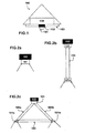
- an optoelectronic device according to the invention will be described by means of the accompanying figures. More specifically, in Fig.1 , an optoelectronic device 100 is represented, comprising a miniaturized spectrometer 102, comprising a light inlet and a first coupling lens 101 displayed between said light inlet and the exterior, designed in such a way that maximizes the light flux coupled from the environmental light into the light inlet of the spectrometer 102.
- the spectrometer 102 and its coupled lens 101 are displayed in the centre of a panel comprising an LED array embedded in an LED panel 103 (more specifically, a printed-circuit board or PCB).
- This position is optimal, since the optical axis of the light inlet and the lens 101 points towards the same direction as the light emitted (i.e. symmetry axis of light angular distribution) by the LED panel 103, therefore capturing environmental light of at least part of the area illuminated by the LEDs.
- the coupling lens 101 may also couple light from other light sources different from the LED panel 103 present in the space under consideration, either by following a straight optical path or after suffering one or multiple reflections within the space. In this way, photons exiting from a variety of sources similar or dissimilar (for example, natural or artificial light) to the optoelectronic device presented in this invention may end up being collected by the coupling lens.
- the displaying of the spectrometer 101 and its lens 102 may vary depending on the intended applications for the optoelectronic device, or depending on the function of each device or on how the devices are distributed within the area, and therefore each device will be controlled in a different way within the system.
- Other embodiments depicting variations on the displaying of the spectrometer 102 will be described later, according to further figures.
- the spectrometer 102 is embodied in a CMOS type microchip, which, in this example, is a micro-spectrometer which comprises a nanoimprinted granting, although a wide range of techniques exist in which said grating could be embodied within the micro-chip, which may also be suitable.
- a commercial example of a suitable micro-spectrometer may be the new series of microchip-embodied spectrometers manufactured by Hamamatsu TM.
- the device 100 comprises a means for modifying the emitted light 104 by either its own LED panel 103 or by other light sources.
- These means are embodied in an electronic microcontroller comprising means for adapting the signals coming from the spectrometer into electric signals suitable to be processed by a microcontroller.
- the microcontroller or a dedicated electronics can adapt a received light-spectrum read out by the mini-spectrometer and, according to a set of rules, depending on different situations and the application intended for the device, modify the emission of part or the whole LED panel 103, by sending them the appropriate current through the electronic drivers.
- a microcontroller optimization algorithm may determine the current that every single LED requires (by reading a calibration table) in order to get a desired overall spectrum of an emitted light. The spectrum of this emitted light is the sum of all the individual LED light spectra.
- the LED array embedded in a LED panel 103 comprises several LEDs, each of them being able to emit in a certain portion of the electromagnetic spectrum, thus covering the whole spectrum range of the particular application that may comprise visible or invisible light or a combination of both. This is useful since, when a specific spectral content has to be emitted, the system is able to vary the intensity of each LED emission in order to obtain the desired spectrum. Therefore, a large number of LEDs (typically in the range between 5 and 50) are used, the higher this number, the more accurate is the reproduction of any arbitrary light spectrum. In order to achieve the best homogeneity and photometric characteristics, the LED PCB 103 may be attached to further optical systems comprising lenses and diffusers.
- the spectrometer 102 and the lens 101 may be hold in direct contact in order to couple the ambient light as shown in the configuration of Fig.1 .
- Other more sophisticated configurations are also possible, as depicted in Fig.2B , where a waveguide in the form of an optical fiber 105 is attached to one end to the lens 101, and in the other end, to a further lens 101 a, similar to the original lens 101.
- FIG.2c Another alternative may be that depicted in Fig.2c , wherein, instead of one, two optical fibers 105a, 105b are displayed within a housing, with one end attached to the first lens 101 and the other end attached to two further lenses 101 b, 101 c. Said lenses are approximately placed in the same plane as the LED array, while the spectrometer 102 may be placed further away from the coupling lenses 101 b and 101c. In this way, a better encapsulation of the optoelectronic device is achieved, allowing also further configurations provided with movable coupling elements 105, 105a, 105b, 101a, 101b, 101c, in order to collect light coming from different regions or directions within the space under consideration. These movable parts could also be governed by the microcontroller.
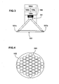
- FIG.3 This encapsulation is better viewed in Fig.3 , wherein packaging of the optoelectronic device 100 comprising the optical fiber configuration depicted in Fig.2c along with the electronic block 106 is given.
- photons collected by the lenses 101 b and 101 c are coupled into the spectrometer 102 through lens 101.
- the compact spectrometer 102 is able to classify these photons according to their energy and provide an electronic signal representing the obtained photon distribution (spectrum).
- An optional signal-conditioning electronic block 106a may be necessary to adapt the signals and the operation modes (for example integration times of the read out process, sensitivity or gain of the CMOS sensor, etc%) between the spectrometer 102 and the microcontroller 106b.
- the microcontroller 106b may compute a particular spectral parameter through a dedicated algorithm and take action either over the electronic drivers 106c that subsequently alter the spectral output of the LED array 103, and/or over the communications and storage block 106d, sending for example a parameter or a pre-stored information over a network.
- a last power electronics block would be also necessary, consisting either of a battery for stand-alone devices and/or a current rectifier for wall-plugged devices but has been deliberately omitted from the drawings for the sake of simplicity.
- the device depicted in Fig.3 may work in any of the light coupling configurations shown in Fig. 2 as well as with multiple optical fibers coupled to the coupling lens 101 (some of them even movable) without loss of generality.
- other sensors could be easily integrated such as temperature sensors, humidity sensors, air flow speed sensors, light intensity sensors (silicon, solar cells, etc..), image (CMOS or CCD arrays) sensors to provide further functionalities without limiting the scope of this invention.
- Figure 4 depicts the base of the optoelectronic device, showing the LED panel 103 and a typical arrangement of the plurality of LEDs 203 within it.
- the basic cell containing the plurality of light emitters 203 that are able to reproduce an arbitrary spectrum, are replicated periodically in order to increase the radiometric (non-visible applications) or luminous (visible applications) power of the overall emitted light.
- this replication provides an increase of the color and spectral homogeneity of the output light.
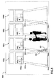
- Fig.5 depicts a system for modifying the environmental light of an area 500, comprising a plurality of optoelectronic devices 100a-100d, whose LED panels 103a-d (only 103a signaled) cover the sub-areas 301a-301d, and whose mini-spectrometers 102a-d (only 102a signaled) cover the sub-areas 300a-300d.
- each device sub-areas 301a-301d
- the "detecting" cones of each spectrometer overlap the cones of light emitted by adjacent devices, as in 303.
- the devices are programmed in a "copy mode" (that is, the means for modifying the emitted light of the LED array are programmed to emit a light that exactly matches the light spectrum obtained by the spectrometer of the same device), when an external change or perturbation in the spectrum of the light occurs in one of the sub-areas covered by an spectrometer of a device, the corresponding device detects said change and starts to emit a light with the detected light spectrum.
- a copy mode that is, the means for modifying the emitted light of the LED array are programmed to emit a light that exactly matches the light spectrum obtained by the spectrometer of the same device
- the area covered by its own LED array is detected by the spectrometers of other devices, triggering these other devices to obtain the new light spectrum and to start emitting a light with said new light spectrum, thus creating a chain reaction that spreads out the original perturbation all over the area covered by all the devices, achieving a new environmental light in response to said first change or perturbation.
- Said change on the light spectrum of a part of the system's area may be caused by a change in the light coming from outside the area (e.g. the sunlight, a flash of an artificial light coming from another space, etc.), an intentionally done change (someone aiming a flashlight towards an spectrometer), or, for example, the entrance of people into the room, or their movement around said room.
- a change in the light coming from outside the area e.g. the sunlight, a flash of an artificial light coming from another space, etc.
- an intentionally done change someone aiming a flashlight towards an spectrometer
- the entrance of people into the room or their movement around said room.
- a change in the environmental light may be caused by a programmed change in the emission of an array of LEDs of a particular optoelectronic device (that is, for example, the emission of a light with a pre-stored light spectrum, programmed by the user, to be performed at certain time of the day), enabling a chain reaction and an overall change of the environmental light of an area by just automatically changing only the emission of only one device of the system.
- a programmed change in the emission of an array of LEDs of a particular optoelectronic device that is, for example, the emission of a light with a pre-stored light spectrum, programmed by the user, to be performed at certain time of the day
- the devices of the system may be programmed differently among them, being a part of them static (not modifying their own light emission upon any spectral change) and another part being modifiable (for example, functioning in a "copy mode" as previously described).
- a possible application of this system may be, for example, the transmission of information on daylighting conditions from a device close to a window, to the interior of the building.
- Further examples include interactive games. For example, a game where the users, having different colored flashlights, have to change the overall lighting of an area by aiming their flash light or torch towards the devices, and where the winner is the team that changes all of the area's lights into their color.
- a further embodiment of the invention may be a system with a plurality of optoelectronic devices displayed as the previously described system, where each characteristic wavelength of the light emitters represents a communication channel.
- a user or a computer program can govern a particular optoelectronic device to serve as an emitter, with a number of channels determined by the number of emitters with different characteristic wavelength it has, and being all type of digital, multi-logic or analog communications protocols allowed in each single channel.
- the rest of the optoelectronic devices are able to receive these spectral components through its own spectrometer, and either continue to transmit the same information to other devices by reproducing a light with the same light spectrum, or decipher the information by decoding the information contained in each communication channel and take the required action.
- information can be encoded within a light spectrum of an emitted light (that is, encoded by using the characteristic wavelength of each single LED as communication channels) and, when emitted by said first optoelectronic device, the emitted light can be detected by other optoelectronic devices which, when configured in a "copy mode" (a device obtains a light spectrum and emits the same light spectrum with its own LED array), cause a chain reaction, the light spectrum comprising encoded information sent by an emit-copy chain through other optoelectronic devices.
- a copy mode a device obtains a light spectrum and emits the same light spectrum with its own LED array
- the system comprises a computer server, connected to all the optoelectronic devices of the system.
- This connection (by means of a communication network via cable, wireless, or any other suitable type of communication between computing devices) enables the optoelectronic devices to send information to said server, corresponding to any change in a detected light spectrum within its corresponding area, thus letting the server control the actions to be performed by any optoelectronic device.
- the decisions taken by the computer server may comprise other inputs such as the time of the day or other relevant information (e.g., historical information corresponding to previously detected spectral changes on other optoelectronic devices, other sensors, etc.).
- the system may be connected to other systems that may or may not be of the same type, via the computing server.
- additional systems may include sensor networks, micro grids, the Internet, other computing servers, or other electronic devices or communications networks of interest.
- the optoelectronic devices can also communicate among each other and, for example, different types of optoelectronic devices can be programmed to control other optoelectronic devices, thus combining the use of the server and optoelectronic devices which can also control actions to be performed by other optoelectronic devices, which can be preferred depending on the application intended for the system, the position of the devices within one or more areas, etc.
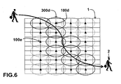
- FIG. 6 An example of a further application of the system is the embodiment of the invention depicted in Fig. 6 , wherein a system comprising a plurality of optoelectronic devices (such as the device 100d or 100e) according to the invention is displayed in an area 1, in such a way that the sum of the ranges 300d of the spectrometers of each device 100d covers practically the whole area, with the aim of people or object tracking in that area, optionally emitting a suitable light accordingly and/or send the information to further devices or computing servers.
- a system comprising a plurality of optoelectronic devices (such as the device 100d or 100e) according to the invention is displayed in an area 1, in such a way that the sum of the ranges 300d of the spectrometers of each device 100d covers practically the whole area, with the aim of people or object tracking in that area, optionally emitting a suitable light accordingly and/or send the information to further devices or computing servers.
- the ranges 300d of the spectrometers overlap partially with each other, thus enabling the system to, whenever a person 2 passes through the area 1, going from one range to another, the overlapping area enables both devices to detect the person and either emit a predetermined light with a predetermined spectral content or send that information for further processing.
- This processing may include identification of individuals or people, based on computational programs.
- the computational algorithms may be comprised in one or several optoelectronic devices (i.e. distributed programming), and/or in computer servers. In order to perform the pattern recognition, the algorithms may include techniques based on soft computing such as neural networks, fuzzy logic and/or other computational advanced paradigms.
- a predetermined pattern based on the received spectral content for that particular person is stored. Then, whenever this pattern is recognized by the system as being a person or object present in a pre-stored database, a signal of identification acknowledge or other information may be sent through a network to other optoelectronic devices or to a server, which may take the required action.
- This information may comprise a set of instructions for other devices requiring them to emit a certain light, or may be sent directly to the drivers that control the LEDs for reproducing a light with a specific spectral content, which could pertain, for example, to a pre-set lighting setting of the user being tracked.
- Said information may also comprise, for example, spectral features corresponding to lights reflected by different types of colors of clothes, types of clothes reflecting light in a specific manner, the type of reflection of human skin or hair, etc...
- movement of an object or a person can also be detected adding other characteristics such as how fast the spectrum changes, or if it changes from one type to another type, etc...
- the information can be also gathered by comparing the spectra that different optoelectronic devices obtain on a particular space. This way of sharing the information through the communication ports among the optoelectronic devices and additional computing servers may help in tracking the changes occurring in the whole space where the lighting system is installed.
- An application of this system may be one where the emitted light by all the devices is low or non-existent and, whenever a moving object or person passes below a particular optoelectronic device, this switches its emission to a comfortable illumination level, thus illuminating the path of the person as it goes.
- a configuration may be achieved where the path in front of the person is illuminated (as seen in the figure, illuminated by, for example, the device 100d, and the devices depicted with their range on a bold traced line) and, also, the light illuminating the path behind or far from the person can be dimmed (as seen in the figure, for example, the device 100e, and the devices depicted with their range on a light traced line), thus only illuminating a portion of the area adjacent to the person (and corresponding to the path he is walking towards), saving electrical energy in the overall process.
- a step to the highly-parallel neural systems is the utilization of several processing elements (neurons).
- a system of optoelectronic devices may be suitable for carrying out such approaches to parallel computing.
- the use of parallel computing on a system of optoelectronic devices may be embodied in the creation of a neural network, where the plurality of optoelectronic devices distributed in a space would act as nodes (artificial neurons) of the neural network.
- the connections or communications among nodes may be performed either through a communication network among them or by light comprising encoded information in its light spectrum, as previously described. In this sense, in such a system, the principles of non-linear, distributed, parallel and local processing and adaptation, normally used in a neural network, can be easily achieved.
- the neural network is provided with a mathematical or computational model for information processing.
- the computational model may be stored and/or executed by the microcontroller of each optoelectronic device, and/or distributed among the plurality of optoelectronic devices, or even governed by a central processing unit through the communication ports such as a personal computer.
- the embodiments of the invention described with reference to the drawings comprise computer apparatus and processes performed in computer apparatus
- the invention also extends to computer programs, particularly computer programs on or in a carrier, adapted for putting the invention into practice.
- the program may be in the form of source code, object code, a code intermediate source and object code such as in partially compiled form, or in any other form suitable for use in the implementation of the processes according to the invention.
- the carrier may be any entity or device capable of carrying the program.
- the carrier may comprise a storage medium, such as a ROM, for example a CD ROM or a semiconductor ROM, or a magnetic recording medium, for example a floppy disc or hard disk.
- a storage medium such as a ROM, for example a CD ROM or a semiconductor ROM, or a magnetic recording medium, for example a floppy disc or hard disk.
- the carrier may be a transmissible carrier such as an electrical or optical signal, which may be conveyed via electrical or optical cable or by radio or other means.
- the carrier may be constituted by such cable or other device or means.
- the carrier may be an integrated circuit in which the program is embedded, the integrated circuit being adapted for performing, or for use in the performance of, the relevant processes.
Priority Applications (1)
| Application Number | Priority Date | Filing Date | Title |
|---|---|---|---|
| PL11700007T PL2604094T3 (pl) | 2011-01-03 | 2011-01-03 | Urządzenie optoelektroniczne, system i sposób do otrzymywania widma światła otoczenia i modyfikowania emitowanego światła |
Applications Claiming Priority (1)
| Application Number | Priority Date | Filing Date | Title |
|---|---|---|---|
| PCT/EP2011/050002 WO2012092956A1 (en) | 2011-01-03 | 2011-01-03 | Optoelectronic device, system and method for obtaining an ambient light spectrum and modifying an emitted light |
Publications (2)
| Publication Number | Publication Date |
|---|---|
| EP2604094A1 EP2604094A1 (en) | 2013-06-19 |
| EP2604094B1 true EP2604094B1 (en) | 2014-07-16 |
Family
ID=44624965
Family Applications (1)
| Application Number | Title | Priority Date | Filing Date |
|---|---|---|---|
| EP11700007.5A Not-in-force EP2604094B1 (en) | 2011-01-03 | 2011-01-03 | Optoelectronic device, system and method for obtaining an ambient light spectrum and modifying an emitted light |
Country Status (13)
| Country | Link |
|---|---|
| US (1) | US9420666B2 (pl) |
| EP (1) | EP2604094B1 (pl) |
| JP (1) | JP5745644B2 (pl) |
| KR (1) | KR20130143102A (pl) |
| CN (1) | CN103299717B (pl) |
| AU (1) | AU2011354248B2 (pl) |
| BR (1) | BR112013017113A2 (pl) |
| CA (1) | CA2822911C (pl) |
| DK (1) | DK2604094T3 (pl) |
| ES (1) | ES2514323T3 (pl) |
| PL (1) | PL2604094T3 (pl) |
| RU (1) | RU2565241C2 (pl) |
| WO (1) | WO2012092956A1 (pl) |
Families Citing this family (18)
| Publication number | Priority date | Publication date | Assignee | Title |
|---|---|---|---|---|
| KR100243464B1 (ko) * | 1996-08-23 | 2000-02-01 | 전주범 | Mpeg-2 부호화기에 있어서 차분펄스 부호변조기 |
| US9288865B2 (en) * | 2012-02-13 | 2016-03-15 | Lumenetix, Inc. | Expert system for establishing a color model for an LED-based lamp |
| US9910828B2 (en) * | 2013-03-12 | 2018-03-06 | Qualcomm Incorporated | Spectrometer for personal context |
| DE102015200133A1 (de) * | 2015-01-08 | 2016-07-14 | Tridonic Gmbh & Co Kg | Lichtsystem mit Anwesenheitserkennung von Personen |
| DE202016008521U1 (de) | 2015-06-08 | 2018-05-17 | Opple Lighting Co. Ltd. | Beleuchtungsvorrichtung und Steuersystem dafür |
| WO2016197880A1 (zh) * | 2015-06-08 | 2016-12-15 | 欧普照明股份有限公司 | 智能照明系统及其控制方法 |
| CN105101535B (zh) * | 2015-06-08 | 2018-02-09 | 欧普照明股份有限公司 | 照明装置及其控制方法和控制系统 |
| DE202016008522U1 (de) | 2015-06-08 | 2018-05-22 | Opple Lighting Co. Ltd. | Beleuchtungsvorrichtung und Steuersystem dafür |
| CN106326983B (zh) * | 2015-06-25 | 2020-01-07 | 江苏灵云数据科技有限公司 | 一种人工神经网络连接的光电转换实现方法和装置 |
| US20170086676A1 (en) * | 2015-09-24 | 2017-03-30 | Johnson & Johnson Vision Care, Inc. | Quantum-dot spectrometers for use in biomedical devices and methods of use |
| US9736597B1 (en) * | 2016-02-17 | 2017-08-15 | Siemens Energy, Inc. | Optical fiber based microphone array for detecting acoustic emissions generated by an area of interest |
| EP3533296B1 (en) * | 2016-10-27 | 2020-06-10 | Signify Holding B.V. | Methods, devices and a system for taking over a light effect between lighting devices, wherein each device covers a different coverage area |
| CA3046787A1 (en) * | 2016-12-15 | 2018-06-21 | Gemological Institute Of America, Inc. (Gia) | Device and method for screening gemstones |
| JP2017228547A (ja) * | 2017-10-06 | 2017-12-28 | パイオニア株式会社 | 照明装置 |
| DE102017221671A1 (de) * | 2017-12-01 | 2019-06-06 | Zumtobel Lighting Gmbh | Bewegungserfassung von Personen mittels Farbsensoren |
| US10859505B2 (en) * | 2018-01-26 | 2020-12-08 | Gemological Institute Of America, Inc. (Gia) | Fluorescence box for gemological applications |
| CN108225277A (zh) * | 2018-03-09 | 2018-06-29 | 深圳臻迪信息技术有限公司 | 无人机的图像获取方法、视觉定位方法、装置、无人机 |
| UA118644C2 (uk) | 2018-09-25 | 2019-02-11 | Василь Олександрович Руських | Портативний переносний освітлювальний пристрій для підводної фото- та відеозйомки |
Family Cites Families (28)
| Publication number | Priority date | Publication date | Assignee | Title |
|---|---|---|---|---|
| US5965873A (en) * | 1997-09-17 | 1999-10-12 | Lockheed Martin Energy Research Corporation | Integrated CMOS spectrometers |
| US7642730B2 (en) * | 2000-04-24 | 2010-01-05 | Philips Solid-State Lighting Solutions, Inc. | Methods and apparatus for conveying information via color of light |
| US6448550B1 (en) * | 2000-04-27 | 2002-09-10 | Agilent Technologies, Inc. | Method and apparatus for measuring spectral content of LED light source and control thereof |
| EP1474666B1 (de) * | 2002-02-13 | 2007-08-08 | Fraunhofer-Gesellschaft zur Förderung der angewandten Forschung e.V. | Quasi-statische auslenkungsvorrichtung für spektrometer |
| US7084973B1 (en) * | 2002-06-11 | 2006-08-01 | Dalsa Inc. | Variable binning CCD for spectroscopy |
| US7057735B2 (en) * | 2002-11-14 | 2006-06-06 | Fitel U.S.A. Corp. | Method for measuring the optical and physical thickness of optically transparent objects |
| US20060018118A1 (en) * | 2004-07-21 | 2006-01-26 | Lee Joon C | Spectrum matching |
| US7345764B2 (en) * | 2005-02-07 | 2008-03-18 | Vladimir Bulovic | Apparatus and method for a slim format spectrometer |
| US7619193B2 (en) * | 2005-06-03 | 2009-11-17 | Koninklijke Philips Electronics N.V. | System and method for controlling a LED luminary |
| CA2611565C (en) * | 2005-08-25 | 2012-04-17 | Institut National D'optique | Flow cytometry analysis across optical fiber |
| JP4600310B2 (ja) * | 2006-02-16 | 2010-12-15 | エプソンイメージングデバイス株式会社 | 電気光学装置、駆動回路及び電子機器 |
| EP1862795A1 (en) * | 2006-05-10 | 2007-12-05 | ABB Schweiz AG | Bulk Material Analyzer System |
| WO2008012715A2 (en) * | 2006-07-28 | 2008-01-31 | Koninklijke Philips Electronics N.V. | An integrated image recognition and spectral detection device and a device and method for automatically controlling the settings of a light by image recognition and spectral detection of the light |
| JP4985061B2 (ja) | 2007-04-06 | 2012-07-25 | 株式会社ニコン | 分光装置および撮像装置 |
| DE102007044556A1 (de) * | 2007-09-07 | 2009-03-12 | Arnold & Richter Cine Technik Gmbh & Co. Betriebs Kg | Verfahren und Vorrichtung zur Einstellung der farb- oder fotometrischen Eigenschaften einer LED-Beleuchtungseinrichtung |
| DE102007042573A1 (de) * | 2007-09-07 | 2009-03-12 | Osram Opto Semiconductors Gmbh | Optisches Beleuchtungsgerät |
| CN101802571A (zh) | 2007-09-11 | 2010-08-11 | 皇家飞利浦电子股份有限公司 | 环境光补偿传感器和过程 |
| FR2922304B1 (fr) * | 2007-10-12 | 2009-11-20 | Sp3H | Dispositif de spectrometrie pour l'analyse d'un fluide |
| US7595786B2 (en) * | 2007-11-13 | 2009-09-29 | Capella Microsystems, Corp. | Illumination system and illumination control method for adaptively adjusting color temperature |
| JP5920686B2 (ja) * | 2007-11-20 | 2016-05-18 | フィリップス ライティング ホールディング ビー ヴィ | コリメート発光装置及び方法 |
| US7728984B2 (en) * | 2008-02-28 | 2010-06-01 | Inficon Gmbh | Method for evaluating a measured parameter |
| JP5111163B2 (ja) * | 2008-03-04 | 2012-12-26 | 浜松ホトニクス株式会社 | 分光器 |
| EP2255247B1 (en) * | 2008-03-18 | 2011-07-20 | Koninklijke Philips Electronics N.V. | Calibration camera with spectral depth |
| US8174695B2 (en) * | 2008-08-15 | 2012-05-08 | The United States Of America As Represented By The Administrator Of The National Aeronautics And Space Administration | Arrayed micro-ring spectrometer system and method of use |
| KR101801681B1 (ko) * | 2009-05-08 | 2017-11-27 | 필립스 라이팅 홀딩 비.브이. | 광 특성 감지 회로 및 방법 |
| DE202009011500U1 (de) * | 2009-08-20 | 2010-12-30 | Arnold & Richter Cine Technik Gmbh & Co. Betriebs Kg | Optisches System für eine LED-Leuchte |
| US8492983B1 (en) * | 2010-05-11 | 2013-07-23 | Analog Technologies Corporation | System and method to address and control serially connected LEDs |
| WO2012012258A2 (en) * | 2010-07-21 | 2012-01-26 | First Solar, Inc. | Temperature-adjusted spectrometer |
-
2011
- 2011-01-03 CA CA2822911A patent/CA2822911C/en active Active
- 2011-01-03 EP EP11700007.5A patent/EP2604094B1/en not_active Not-in-force
- 2011-01-03 CN CN201180063762.0A patent/CN103299717B/zh not_active Expired - Fee Related
- 2011-01-03 ES ES11700007.5T patent/ES2514323T3/es active Active
- 2011-01-03 US US13/978,134 patent/US9420666B2/en active Active
- 2011-01-03 DK DK11700007.5T patent/DK2604094T3/da active
- 2011-01-03 BR BR112013017113-8A patent/BR112013017113A2/pt not_active Application Discontinuation
- 2011-01-03 WO PCT/EP2011/050002 patent/WO2012092956A1/en active Application Filing
- 2011-01-03 PL PL11700007T patent/PL2604094T3/pl unknown
- 2011-01-03 AU AU2011354248A patent/AU2011354248B2/en not_active Ceased
- 2011-01-03 JP JP2013546618A patent/JP5745644B2/ja not_active Expired - Fee Related
- 2011-01-03 RU RU2013136394/07A patent/RU2565241C2/ru not_active IP Right Cessation
- 2011-01-03 KR KR1020137018669A patent/KR20130143102A/ko not_active Application Discontinuation
Also Published As
| Publication number | Publication date |
|---|---|
| RU2013136394A (ru) | 2015-02-10 |
| CN103299717A (zh) | 2013-09-11 |
| JP2014508377A (ja) | 2014-04-03 |
| EP2604094A1 (en) | 2013-06-19 |
| ES2514323T3 (es) | 2014-10-28 |
| WO2012092956A1 (en) | 2012-07-12 |
| CA2822911C (en) | 2018-07-10 |
| JP5745644B2 (ja) | 2015-07-08 |
| CA2822911A1 (en) | 2012-07-12 |
| DK2604094T3 (da) | 2014-10-06 |
| US20130293116A1 (en) | 2013-11-07 |
| PL2604094T3 (pl) | 2015-02-27 |
| CN103299717B (zh) | 2015-11-25 |
| AU2011354248B2 (en) | 2015-08-20 |
| US9420666B2 (en) | 2016-08-16 |
| RU2565241C2 (ru) | 2015-10-20 |
| KR20130143102A (ko) | 2013-12-30 |
| AU2011354248A1 (en) | 2013-07-11 |
| BR112013017113A2 (pt) | 2020-10-27 |
Similar Documents
| Publication | Publication Date | Title |
|---|---|---|
| EP2604094B1 (en) | Optoelectronic device, system and method for obtaining an ambient light spectrum and modifying an emitted light | |
| US7521872B2 (en) | Integrated lamp with feedback and wireless control | |
| CN103152905B (zh) | 照明系统 | |
| JP5572697B2 (ja) | 画像に基づく照明制御及びセキュリティ制御のためのシステム及び装置 | |
| CN104429161A (zh) | 自动调适照明单元的光输出的方法和装置 | |
| CN101932873A (zh) | 用于在舞台照明应用中提供基于led的聚光灯照明的方法和设备 | |
| RU2696003C2 (ru) | Автоматическое приведение в действие осветительных модулей | |
| CN102342184A (zh) | 自动配置照明 | |
| CN109618445A (zh) | 用于可适配照明单元的方法和设备以从外部源接收驱动数据 | |
| US11018183B2 (en) | Source sensitive optic with reconfigurable chip-on-board light emitting diode array | |
| US10458844B2 (en) | Reconfigurable optical fiber spectrometer in a lighting device | |
| US20230019044A1 (en) | Electronic Control Device | |
| CN106171046B (zh) | 将装置重置为工厂新状态 | |
| CN108171186A (zh) | 一种指纹识别装置和方法 | |
| KR102405185B1 (ko) | 재구성 가능한 칩-온-보드 발광 다이오드 어레이를 갖는 소스 감지 광학계 | |
| CN116867136A (zh) | 一种基于人工智能技术的灯光控制和商品热度分析系统及方法 | |
| AU2018309565A1 (en) | A control method, system and device |
Legal Events
| Date | Code | Title | Description |
|---|---|---|---|
| PUAI | Public reference made under article 153(3) epc to a published international application that has entered the european phase |
Free format text: ORIGINAL CODE: 0009012 |
|
| 17P | Request for examination filed |
Effective date: 20130311 |
|
| AK | Designated contracting states |
Kind code of ref document: A1 Designated state(s): AL AT BE BG CH CY CZ DE DK EE ES FI FR GB GR HR HU IE IS IT LI LT LU LV MC MK MT NL NO PL PT RO RS SE SI SK SM TR |
|
| 17Q | First examination report despatched |
Effective date: 20130606 |
|
| GRAP | Despatch of communication of intention to grant a patent |
Free format text: ORIGINAL CODE: EPIDOSNIGR1 |
|
| DAX | Request for extension of the european patent (deleted) | ||
| INTG | Intention to grant announced |
Effective date: 20140121 |
|
| RIN1 | Information on inventor provided before grant (corrected) |
Inventor name: CARRERAS MOLINS, JOSEP MARIA |
|
| GRAS | Grant fee paid |
Free format text: ORIGINAL CODE: EPIDOSNIGR3 |
|
| GRAA | (expected) grant |
Free format text: ORIGINAL CODE: 0009210 |
|
| AK | Designated contracting states |
Kind code of ref document: B1 Designated state(s): AL AT BE BG CH CY CZ DE DK EE ES FI FR GB GR HR HU IE IS IT LI LT LU LV MC MK MT NL NO PL PT RO RS SE SI SK SM TR |
|
| REG | Reference to a national code |
Ref country code: GB Ref legal event code: FG4D |
|
| REG | Reference to a national code |
Ref country code: CH Ref legal event code: EP |
|
| REG | Reference to a national code |
Ref country code: IE Ref legal event code: FG4D |
|
| REG | Reference to a national code |
Ref country code: AT Ref legal event code: REF Ref document number: 678289 Country of ref document: AT Kind code of ref document: T Effective date: 20140815 |
|
| REG | Reference to a national code |
Ref country code: DE Ref legal event code: R096 Ref document number: 602011008385 Country of ref document: DE Effective date: 20140828 |
|
| REG | Reference to a national code |
Ref country code: DK Ref legal event code: T3 Effective date: 20141002 |
|
| REG | Reference to a national code |
Ref country code: ES Ref legal event code: FG2A Ref document number: 2514323 Country of ref document: ES Kind code of ref document: T3 Effective date: 20141028 |
|
| REG | Reference to a national code |
Ref country code: SE Ref legal event code: TRGR |
|
| REG | Reference to a national code |
Ref country code: NL Ref legal event code: T3 |
|
| REG | Reference to a national code |
Ref country code: NO Ref legal event code: T2 Effective date: 20140716 |
|
| REG | Reference to a national code |
Ref country code: LT Ref legal event code: MG4D |
|
| PG25 | Lapsed in a contracting state [announced via postgrant information from national office to epo] |
Ref country code: PT Free format text: LAPSE BECAUSE OF FAILURE TO SUBMIT A TRANSLATION OF THE DESCRIPTION OR TO PAY THE FEE WITHIN THE PRESCRIBED TIME-LIMIT Effective date: 20141117 Ref country code: GR Free format text: LAPSE BECAUSE OF FAILURE TO SUBMIT A TRANSLATION OF THE DESCRIPTION OR TO PAY THE FEE WITHIN THE PRESCRIBED TIME-LIMIT Effective date: 20141017 Ref country code: LT Free format text: LAPSE BECAUSE OF FAILURE TO SUBMIT A TRANSLATION OF THE DESCRIPTION OR TO PAY THE FEE WITHIN THE PRESCRIBED TIME-LIMIT Effective date: 20140716 Ref country code: BG Free format text: LAPSE BECAUSE OF FAILURE TO SUBMIT A TRANSLATION OF THE DESCRIPTION OR TO PAY THE FEE WITHIN THE PRESCRIBED TIME-LIMIT Effective date: 20141016 |
|
| PG25 | Lapsed in a contracting state [announced via postgrant information from national office to epo] |
Ref country code: RS Free format text: LAPSE BECAUSE OF FAILURE TO SUBMIT A TRANSLATION OF THE DESCRIPTION OR TO PAY THE FEE WITHIN THE PRESCRIBED TIME-LIMIT Effective date: 20140716 Ref country code: LV Free format text: LAPSE BECAUSE OF FAILURE TO SUBMIT A TRANSLATION OF THE DESCRIPTION OR TO PAY THE FEE WITHIN THE PRESCRIBED TIME-LIMIT Effective date: 20140716 Ref country code: IS Free format text: LAPSE BECAUSE OF FAILURE TO SUBMIT A TRANSLATION OF THE DESCRIPTION OR TO PAY THE FEE WITHIN THE PRESCRIBED TIME-LIMIT Effective date: 20141116 Ref country code: CY Free format text: LAPSE BECAUSE OF FAILURE TO SUBMIT A TRANSLATION OF THE DESCRIPTION OR TO PAY THE FEE WITHIN THE PRESCRIBED TIME-LIMIT Effective date: 20140716 |
|
| REG | Reference to a national code |
Ref country code: PL Ref legal event code: T3 |
|
| REG | Reference to a national code |
Ref country code: DE Ref legal event code: R097 Ref document number: 602011008385 Country of ref document: DE |
|
| PG25 | Lapsed in a contracting state [announced via postgrant information from national office to epo] |
Ref country code: SK Free format text: LAPSE BECAUSE OF FAILURE TO SUBMIT A TRANSLATION OF THE DESCRIPTION OR TO PAY THE FEE WITHIN THE PRESCRIBED TIME-LIMIT Effective date: 20140716 Ref country code: EE Free format text: LAPSE BECAUSE OF FAILURE TO SUBMIT A TRANSLATION OF THE DESCRIPTION OR TO PAY THE FEE WITHIN THE PRESCRIBED TIME-LIMIT Effective date: 20140716 Ref country code: CZ Free format text: LAPSE BECAUSE OF FAILURE TO SUBMIT A TRANSLATION OF THE DESCRIPTION OR TO PAY THE FEE WITHIN THE PRESCRIBED TIME-LIMIT Effective date: 20140716 Ref country code: RO Free format text: LAPSE BECAUSE OF FAILURE TO SUBMIT A TRANSLATION OF THE DESCRIPTION OR TO PAY THE FEE WITHIN THE PRESCRIBED TIME-LIMIT Effective date: 20140716 |
|
| PLBE | No opposition filed within time limit |
Free format text: ORIGINAL CODE: 0009261 |
|
| STAA | Information on the status of an ep patent application or granted ep patent |
Free format text: STATUS: NO OPPOSITION FILED WITHIN TIME LIMIT |
|
| 26N | No opposition filed |
Effective date: 20150417 |
|
| PG25 | Lapsed in a contracting state [announced via postgrant information from national office to epo] |
Ref country code: LU Free format text: LAPSE BECAUSE OF FAILURE TO SUBMIT A TRANSLATION OF THE DESCRIPTION OR TO PAY THE FEE WITHIN THE PRESCRIBED TIME-LIMIT Effective date: 20150103 |
|
| PG25 | Lapsed in a contracting state [announced via postgrant information from national office to epo] |
Ref country code: MC Free format text: LAPSE BECAUSE OF FAILURE TO SUBMIT A TRANSLATION OF THE DESCRIPTION OR TO PAY THE FEE WITHIN THE PRESCRIBED TIME-LIMIT Effective date: 20140716 |
|
| PG25 | Lapsed in a contracting state [announced via postgrant information from national office to epo] |
Ref country code: SI Free format text: LAPSE BECAUSE OF FAILURE TO SUBMIT A TRANSLATION OF THE DESCRIPTION OR TO PAY THE FEE WITHIN THE PRESCRIBED TIME-LIMIT Effective date: 20140716 |
|
| REG | Reference to a national code |
Ref country code: FR Ref legal event code: PLFP Year of fee payment: 6 |
|
| PG25 | Lapsed in a contracting state [announced via postgrant information from national office to epo] |
Ref country code: MT Free format text: LAPSE BECAUSE OF FAILURE TO SUBMIT A TRANSLATION OF THE DESCRIPTION OR TO PAY THE FEE WITHIN THE PRESCRIBED TIME-LIMIT Effective date: 20140716 |
|
| REG | Reference to a national code |
Ref country code: FR Ref legal event code: PLFP Year of fee payment: 7 |
|
| PG25 | Lapsed in a contracting state [announced via postgrant information from national office to epo] |
Ref country code: SM Free format text: LAPSE BECAUSE OF FAILURE TO SUBMIT A TRANSLATION OF THE DESCRIPTION OR TO PAY THE FEE WITHIN THE PRESCRIBED TIME-LIMIT Effective date: 20140716 Ref country code: HU Free format text: LAPSE BECAUSE OF FAILURE TO SUBMIT A TRANSLATION OF THE DESCRIPTION OR TO PAY THE FEE WITHIN THE PRESCRIBED TIME-LIMIT; INVALID AB INITIO Effective date: 20110103 |
|
| PG25 | Lapsed in a contracting state [announced via postgrant information from national office to epo] |
Ref country code: HR Free format text: LAPSE BECAUSE OF FAILURE TO SUBMIT A TRANSLATION OF THE DESCRIPTION OR TO PAY THE FEE WITHIN THE PRESCRIBED TIME-LIMIT Effective date: 20140716 |
|
| PG25 | Lapsed in a contracting state [announced via postgrant information from national office to epo] |
Ref country code: TR Free format text: LAPSE BECAUSE OF FAILURE TO SUBMIT A TRANSLATION OF THE DESCRIPTION OR TO PAY THE FEE WITHIN THE PRESCRIBED TIME-LIMIT Effective date: 20140716 |
|
| REG | Reference to a national code |
Ref country code: FR Ref legal event code: PLFP Year of fee payment: 8 |
|
| PG25 | Lapsed in a contracting state [announced via postgrant information from national office to epo] |
Ref country code: MK Free format text: LAPSE BECAUSE OF FAILURE TO SUBMIT A TRANSLATION OF THE DESCRIPTION OR TO PAY THE FEE WITHIN THE PRESCRIBED TIME-LIMIT Effective date: 20140716 |
|
| PG25 | Lapsed in a contracting state [announced via postgrant information from national office to epo] |
Ref country code: AL Free format text: LAPSE BECAUSE OF FAILURE TO SUBMIT A TRANSLATION OF THE DESCRIPTION OR TO PAY THE FEE WITHIN THE PRESCRIBED TIME-LIMIT Effective date: 20140716 |
|
| REG | Reference to a national code |
Ref country code: DE Ref legal event code: R081 Ref document number: 602011008385 Country of ref document: DE Owner name: LEDMOTIVE TECHNOLOGIES, S.L., ES Free format text: FORMER OWNER: FUNDACIO INSTITUT DE RECERCA DE L'ENERGIA DE CATALUNYA, SANT ADRIA DEL BESOS, ES |
|
| REG | Reference to a national code |
Ref country code: NO Ref legal event code: CHAD Owner name: LEDMOTIVE TECHNOLOGIES, ES |
|
| REG | Reference to a national code |
Ref country code: ES Ref legal event code: PC2A Owner name: LEDMOTIVE TECHNOLOGIES, S.L. Effective date: 20181204 |
|
| REG | Reference to a national code |
Ref country code: GB Ref legal event code: 732E Free format text: REGISTERED BETWEEN 20181203 AND 20181205 |
|
| REG | Reference to a national code |
Ref country code: DE Ref legal event code: R081 Ref document number: 602011008385 Country of ref document: DE Owner name: LEDMOTIVE TECHNOLOGIES, S.L., ES Free format text: FORMER OWNER: LEDMOTIVE TECHNNOLOGIES, S.L., SANT ADRIA DEL BESOS, ES |
|
| REG | Reference to a national code |
Ref country code: BE Ref legal event code: FP Effective date: 20141013 Ref country code: BE Ref legal event code: PD Owner name: LEDMOTIVE TECHNOLOGIES, S.L.; ES Free format text: DETAILS ASSIGNMENT: CHANGE OF OWNER(S), CESSION; FORMER OWNER NAME: FUNDACIO INSTITUT DE RECERCA DE L'ENERGIA DE CATALUNYA Effective date: 20181129 |
|
| PGFP | Annual fee paid to national office [announced via postgrant information from national office to epo] |
Ref country code: PL Payment date: 20181220 Year of fee payment: 9 |
|
| REG | Reference to a national code |
Ref country code: NL Ref legal event code: PD Owner name: LEDMOTIVE TECHNOLOGIES, S.L.; ES Free format text: DETAILS ASSIGNMENT: CHANGE OF OWNER(S), ASSIGNMENT; FORMER OWNER NAME: FUNDACIO INSTITUT DE RECERCA DE L'ENERGIA DE CATALUNYA Effective date: 20181204 |
|
| PGFP | Annual fee paid to national office [announced via postgrant information from national office to epo] |
Ref country code: IT Payment date: 20190123 Year of fee payment: 9 Ref country code: CH Payment date: 20190204 Year of fee payment: 9 |
|
| PGFP | Annual fee paid to national office [announced via postgrant information from national office to epo] |
Ref country code: DK Payment date: 20190129 Year of fee payment: 9 Ref country code: SE Payment date: 20190129 Year of fee payment: 9 Ref country code: AT Payment date: 20181219 Year of fee payment: 9 |
|
| REG | Reference to a national code |
Ref country code: DK Ref legal event code: EBP Effective date: 20200131 Ref country code: CH Ref legal event code: PL |
|
| REG | Reference to a national code |
Ref country code: SE Ref legal event code: EUG |
|
| REG | Reference to a national code |
Ref country code: AT Ref legal event code: MM01 Ref document number: 678289 Country of ref document: AT Kind code of ref document: T Effective date: 20200103 |
|
| REG | Reference to a national code |
Ref country code: SE Ref legal event code: EUG |
|
| PG25 | Lapsed in a contracting state [announced via postgrant information from national office to epo] |
Ref country code: SE Free format text: LAPSE BECAUSE OF NON-PAYMENT OF DUE FEES Effective date: 20200104 |
|
| PG25 | Lapsed in a contracting state [announced via postgrant information from national office to epo] |
Ref country code: AT Free format text: LAPSE BECAUSE OF NON-PAYMENT OF DUE FEES Effective date: 20200103 Ref country code: CH Free format text: LAPSE BECAUSE OF NON-PAYMENT OF DUE FEES Effective date: 20200131 Ref country code: LI Free format text: LAPSE BECAUSE OF NON-PAYMENT OF DUE FEES Effective date: 20200131 |
|
| PG25 | Lapsed in a contracting state [announced via postgrant information from national office to epo] |
Ref country code: IT Free format text: LAPSE BECAUSE OF NON-PAYMENT OF DUE FEES Effective date: 20200103 Ref country code: DK Free format text: LAPSE BECAUSE OF NON-PAYMENT OF DUE FEES Effective date: 20200131 Ref country code: IE Free format text: LAPSE BECAUSE OF NON-PAYMENT OF DUE FEES Effective date: 20200103 |
|
| PG25 | Lapsed in a contracting state [announced via postgrant information from national office to epo] |
Ref country code: PL Free format text: LAPSE BECAUSE OF NON-PAYMENT OF DUE FEES Effective date: 20200103 |
|
| PGFP | Annual fee paid to national office [announced via postgrant information from national office to epo] |
Ref country code: GB Payment date: 20220127 Year of fee payment: 12 Ref country code: FI Payment date: 20220127 Year of fee payment: 12 Ref country code: DE Payment date: 20220127 Year of fee payment: 12 |
|
| PGFP | Annual fee paid to national office [announced via postgrant information from national office to epo] |
Ref country code: NO Payment date: 20220127 Year of fee payment: 12 Ref country code: NL Payment date: 20220126 Year of fee payment: 12 Ref country code: FR Payment date: 20220125 Year of fee payment: 12 Ref country code: ES Payment date: 20220201 Year of fee payment: 12 Ref country code: BE Payment date: 20220127 Year of fee payment: 12 |
|
| REG | Reference to a national code |
Ref country code: DE Ref legal event code: R119 Ref document number: 602011008385 Country of ref document: DE |
|
| REG | Reference to a national code |
Ref country code: NO Ref legal event code: MMEP |
|
| REG | Reference to a national code |
Ref country code: NL Ref legal event code: MM Effective date: 20230201 |
|
| GBPC | Gb: european patent ceased through non-payment of renewal fee |
Effective date: 20230103 |
|
| REG | Reference to a national code |
Ref country code: BE Ref legal event code: MM Effective date: 20230131 |
|
| PG25 | Lapsed in a contracting state [announced via postgrant information from national office to epo] |
Ref country code: NO Free format text: LAPSE BECAUSE OF NON-PAYMENT OF DUE FEES Effective date: 20230131 Ref country code: NL Free format text: LAPSE BECAUSE OF NON-PAYMENT OF DUE FEES Effective date: 20230201 Ref country code: GB Free format text: LAPSE BECAUSE OF NON-PAYMENT OF DUE FEES Effective date: 20230103 Ref country code: FI Free format text: LAPSE BECAUSE OF NON-PAYMENT OF DUE FEES Effective date: 20230103 Ref country code: DE Free format text: LAPSE BECAUSE OF NON-PAYMENT OF DUE FEES Effective date: 20230801 |
|
| PG25 | Lapsed in a contracting state [announced via postgrant information from national office to epo] |
Ref country code: FR Free format text: LAPSE BECAUSE OF NON-PAYMENT OF DUE FEES Effective date: 20230131 Ref country code: BE Free format text: LAPSE BECAUSE OF NON-PAYMENT OF DUE FEES Effective date: 20230131 |
|
| REG | Reference to a national code |
Ref country code: ES Ref legal event code: FD2A Effective date: 20240229 |
|
| PG25 | Lapsed in a contracting state [announced via postgrant information from national office to epo] |
Ref country code: ES Free format text: LAPSE BECAUSE OF NON-PAYMENT OF DUE FEES Effective date: 20230104 |
|
| PG25 | Lapsed in a contracting state [announced via postgrant information from national office to epo] |
Ref country code: ES Free format text: LAPSE BECAUSE OF NON-PAYMENT OF DUE FEES Effective date: 20230104 |