EP2602495B1 - Baugruppe für ein Baukastengetriebe - Google Patents
Baugruppe für ein Baukastengetriebe Download PDFInfo
- Publication number
- EP2602495B1 EP2602495B1 EP12195936.5A EP12195936A EP2602495B1 EP 2602495 B1 EP2602495 B1 EP 2602495B1 EP 12195936 A EP12195936 A EP 12195936A EP 2602495 B1 EP2602495 B1 EP 2602495B1
- Authority
- EP
- European Patent Office
- Prior art keywords
- bore
- securing ring
- module
- bore securing
- groove
- Prior art date
- Legal status (The legal status is an assumption and is not a legal conclusion. Google has not performed a legal analysis and makes no representation as to the accuracy of the status listed.)
- Active
Links
- 230000005540 biological transmission Effects 0.000 claims description 23
- 125000006850 spacer group Chemical group 0.000 claims description 19
- 238000000034 method Methods 0.000 claims description 7
- 210000002105 tongue Anatomy 0.000 claims description 4
- 229910000639 Spring steel Inorganic materials 0.000 claims description 2
- 239000002184 metal Substances 0.000 claims 1
- 230000000712 assembly Effects 0.000 description 4
- 238000000429 assembly Methods 0.000 description 4
- 238000010276 construction Methods 0.000 description 1
- 230000001419 dependent effect Effects 0.000 description 1
- 238000011161 development Methods 0.000 description 1
- 230000018109 developmental process Effects 0.000 description 1
- 230000000694 effects Effects 0.000 description 1
- 230000005489 elastic deformation Effects 0.000 description 1
- 238000003780 insertion Methods 0.000 description 1
- 230000037431 insertion Effects 0.000 description 1
- 230000002040 relaxant effect Effects 0.000 description 1
Images


Classifications
-
- F—MECHANICAL ENGINEERING; LIGHTING; HEATING; WEAPONS; BLASTING
- F16—ENGINEERING ELEMENTS AND UNITS; GENERAL MEASURES FOR PRODUCING AND MAINTAINING EFFECTIVE FUNCTIONING OF MACHINES OR INSTALLATIONS; THERMAL INSULATION IN GENERAL
- F16B—DEVICES FOR FASTENING OR SECURING CONSTRUCTIONAL ELEMENTS OR MACHINE PARTS TOGETHER, e.g. NAILS, BOLTS, CIRCLIPS, CLAMPS, CLIPS OR WEDGES; JOINTS OR JOINTING
- F16B21/00—Means for preventing relative axial movement of a pin, spigot, shaft or the like and a member surrounding it; Stud-and-socket releasable fastenings
- F16B21/10—Means for preventing relative axial movement of a pin, spigot, shaft or the like and a member surrounding it; Stud-and-socket releasable fastenings by separate parts
- F16B21/16—Means for preventing relative axial movement of a pin, spigot, shaft or the like and a member surrounding it; Stud-and-socket releasable fastenings by separate parts with grooves or notches in the pin or shaft
- F16B21/18—Means for preventing relative axial movement of a pin, spigot, shaft or the like and a member surrounding it; Stud-and-socket releasable fastenings by separate parts with grooves or notches in the pin or shaft with circlips or like resilient retaining devices, i.e. resilient in the plane of the ring or the like; Details
- F16B21/183—Means for preventing relative axial movement of a pin, spigot, shaft or the like and a member surrounding it; Stud-and-socket releasable fastenings by separate parts with grooves or notches in the pin or shaft with circlips or like resilient retaining devices, i.e. resilient in the plane of the ring or the like; Details internal, i.e. with spreading action
-
- F—MECHANICAL ENGINEERING; LIGHTING; HEATING; WEAPONS; BLASTING
- F16—ENGINEERING ELEMENTS AND UNITS; GENERAL MEASURES FOR PRODUCING AND MAINTAINING EFFECTIVE FUNCTIONING OF MACHINES OR INSTALLATIONS; THERMAL INSULATION IN GENERAL
- F16C—SHAFTS; FLEXIBLE SHAFTS; ELEMENTS OR CRANKSHAFT MECHANISMS; ROTARY BODIES OTHER THAN GEARING ELEMENTS; BEARINGS
- F16C35/00—Rigid support of bearing units; Housings, e.g. caps, covers
- F16C35/04—Rigid support of bearing units; Housings, e.g. caps, covers in the case of ball or roller bearings
- F16C35/06—Mounting or dismounting of ball or roller bearings; Fixing them onto shaft or in housing
- F16C35/067—Fixing them in a housing
-
- F—MECHANICAL ENGINEERING; LIGHTING; HEATING; WEAPONS; BLASTING
- F16—ENGINEERING ELEMENTS AND UNITS; GENERAL MEASURES FOR PRODUCING AND MAINTAINING EFFECTIVE FUNCTIONING OF MACHINES OR INSTALLATIONS; THERMAL INSULATION IN GENERAL
- F16C—SHAFTS; FLEXIBLE SHAFTS; ELEMENTS OR CRANKSHAFT MECHANISMS; ROTARY BODIES OTHER THAN GEARING ELEMENTS; BEARINGS
- F16C19/00—Bearings with rolling contact, for exclusively rotary movement
- F16C19/54—Systems consisting of a plurality of bearings with rolling friction
- F16C19/541—Systems consisting of juxtaposed rolling bearings including at least one angular contact bearing
- F16C19/542—Systems consisting of juxtaposed rolling bearings including at least one angular contact bearing with two rolling bearings with angular contact
- F16C19/543—Systems consisting of juxtaposed rolling bearings including at least one angular contact bearing with two rolling bearings with angular contact in O-arrangement
-
- F—MECHANICAL ENGINEERING; LIGHTING; HEATING; WEAPONS; BLASTING
- F16—ENGINEERING ELEMENTS AND UNITS; GENERAL MEASURES FOR PRODUCING AND MAINTAINING EFFECTIVE FUNCTIONING OF MACHINES OR INSTALLATIONS; THERMAL INSULATION IN GENERAL
- F16C—SHAFTS; FLEXIBLE SHAFTS; ELEMENTS OR CRANKSHAFT MECHANISMS; ROTARY BODIES OTHER THAN GEARING ELEMENTS; BEARINGS
- F16C2361/00—Apparatus or articles in engineering in general
- F16C2361/61—Toothed gear systems, e.g. support of pinion shafts
Definitions
- the invention relates to an assembly for a modular transmission and provided with the module modular transmission.
- the assembly includes a bore lock ring comprising first and second actuators and a circular arc spring member having first and opposite second ends, the ends defining a recess of the spring member.
- the invention relates to a method for assembly and disassembly of assemblies according to the invention to the modular transmission.
- a previously known bore securing ring usually serves as an axial securing or axial fixing of assemblies within receiving bores.
- the respective assembly is divided into two halves, between which the bore securing ring is arranged. It engages in the mounted state in an internally provided annular groove of the receiving bore. He takes in this way axially acting on the assembly forces and transmits them to the annular groove of the receiving bore. Likewise, axial forces are transmitted from the receiving bore to the assembly.
- Bore safety rings are slotted rings. They have spring elements which allow an elastic deformation of the bore securing ring.
- a bore securing ring for a receiving bore has an outer diameter on, which is larger than the inner diameter of the receiving bore.
- the bore securing ring In order to be able to be introduced into the receiving bore for mounting, the bore securing ring must be elastically deformed so that its outer diameter is smaller than the inner diameter of the receiving bore. The deformation is effected via actuators, which are usually provided with eye holes and arranged at the ends of the spring element. The designated below as a recess slot of the bore locking ring is compressed. In this case, the outer contour of a bore securing ring is approximately circular. This allows the introduction of the taut bore retaining ring in a bore.
- a bore securing ring known as such: it comprises two actuating elements and a circular-arc-shaped spring element.
- the actuating elements are arranged outside the outer diameter of the bore securing ring. It is intended in particular for fastening a roller bearing.
- the previously known bore securing ring has the disadvantage that it requires a complicated assembly or disassembly, which generally comprises several separate working steps.
- certain assemblies may not yet have been mounted during assembly in order to be able to place the bore securing ring.
- disassembly other components may have to be dismantled beforehand in order to disassemble the bore lock ring.
- a quick and easy assembly and disassembly is not possible.
- the use of pre-assembled modules is so difficult.
- the object of the invention is to provide an improved assembly whose application allows pre-assembly and avoids the above-mentioned disadvantages.
- the solution comprises an assembly for a modular transmission, which comprises a first and a second spacer sleeve, wherein the spacer sleeves each have a half of an outer groove of the transmission component, and in the outer groove, a bore securing ring is provided, which comprises a first and a second actuating element and a circular arc-shaped spring element comprising a first and an opposite second end.
- the bore securing ring comprises at the first end a first outwardly facing projection and at the second end a second outwardly facing projection, wherein the first and second actuating element are arranged outside the outer diameter of the bore securing ring, wherein the bore securing ring is fully retractable into the outer groove.
- the solution further comprises a modular transmission having at least one assembly and a receiving bore for receiving the assembly, wherein the assembly comprises a first and a second spacer sleeve, wherein the spacer sleeves each having a half of an outer groove of the assembly, and provided in the outer groove a bore locking ring is comprising a first and a second actuating element and a circular-arc-shaped spring element having a first and an opposite second end, and the bore securing ring at the first end comprises a first outwardly facing projection and at the second end a second outwardly facing projection the first and second actuators are located outside the outer diameter of the bore lock ring on the protrusions, the bore lock ring being fully retractable into the outer groove; wherein the receiving bore has an axial slot at which a radially extending groove begins and ends, and the assembly has an outer groove which is aligned in the mounted state with the groove.
- the bore securing ring is designed as described above.
- the invention is based on the idea of being able to actuate the bore safety ring in the sunk state without having to disassemble other components beforehand.
- the bore securing ring at each end of the spring element has a projection.
- the projections project radially outward beyond the contour circle defined by the spring element. Accordingly, the "free" ends of the projections are outside of a circle defined by the spring element.
- the projections are designed so that they are introduced in the arrangement of the bore securing ring in a groove within the receiving bore through the slot of the receiving bore according to the invention. If the bore securing ring is arranged in the groove, the projections protrude through the slot from the receiving bore and can continue to be actuated.
- the recessed bore securing ring according to the invention can accordingly be actuated from outside the receiving bore, even if it is arranged between a countersunk assembly and a receiving bore.
- the modules of the assembly are arranged together, wherein the bore securing ring according to the invention is arranged in an outer groove provided for him.
- the adjacent modules form the side walls of the outer groove.
- the adjacent modules preferably have a centering aid, which prevents slipping.
- the bore lock ring need not be bent during assembly of the assembly.
- the module modules are fastened together.
- the groove of the receiving bore on conical side walls. This facilitates the engagement of the bore securing ring.
- the invention allows the use of harder executed by the leverage of the projections
- the projections are designed as elongated webs, which point radially outward from the center point of the spring element.
- the projections end at a radius corresponding to a circle with 10 to 100% larger diameter than the outer diameter of the bore securing ring.
- the actuators are preferably designed as eye holes.
- the eye holes can engage in a conventional manner, a special pliers, through which the bore locking ring can be stretched and assembled or disassembled.
- the assembly, the modular transmission and the bore locking ring are provided in accordance with the above description.
- the method comprises the following steps: arranging a first spacer sleeve, a bore securing ring according to the invention and a second spacer sleeve to form an assembly; Attaching the assembly parts to each other; Tensioning the bore lock ring on the assembly by force on the actuators so that the bore lock ring is fully recessed in the outer groove; Arranging the assembly in the receiving bore of a modular gearbox with cocked bore safety ring; and relax the Bohrungsommesrings on the module used by solving the force on the actuating elements, so that the bore securing ring is half each sunk in the groove and the outer groove.
- a method for disassembling an assembly to a modular transmission by means of a bore securing ring comprises the following steps: clamping the bore lock ring; and removing the tapped bore retainer assembly from the receiving bore.
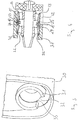
- a first embodiment of a bore securing ring 10 is shown with a circular spring element 11 having a first end 12 and a second opposite end 13.
- the two ends 12, 13 define an opening 18 of the spring element 11.
- the bore securing ring 10 comprises a first projection 14 and a second projection 15, which are respectively arranged at the two ends 12, 13 of the spring element 11.
- the two projections 14, 15 are arranged with respect to the circular-arc-shaped spring element 11 in a radially projecting direction.
- the free ends of the projections 14, 15 form portions 110, 111, which are arranged opposite the ends 12, 13 of the spring element 11.
- an actuating element 16, 17 is arranged in each case.
- the projections 14, 15 have a length which is between 10% and 100% of the diameter of the spring element 11. The dimensions are chosen so that the sections 110, 111 are arranged with the actuators 16, 17 outside the outer diameter of the bore securing ring.
- the spring element 11 has a thickness D, which is characterized by the difference of the inner and outer diameter of Bore safety ring is defined.
- a width B of the spring element 11 is defined in the axial direction.
- the actuators 16, 17 may be configured as eye holes into which a special pliers may engage to tighten the bore lock ring.
- the eye holes are arranged in the sections 110, 111 of the projections 14, 15.
- the diameter of the bore securing ring 10 is changed under the action of a force on the actuating elements 16, 17. It can be reduced by the operation as needed. As a result, the width of the slot-like opening 18 narrows.
- the spring element 11 is made of spring steel.
- a plastic with the appropriate properties can be used.
- the bore securing ring 10 is provided with tongues 101 - 106, which can be arranged over its entire circumference on the inside of the circular arc. These tongues 101 - 106 serve to increase the contact between assembly 20 and bore securing ring 10 and thus the holding action.
- the second embodiment corresponds to the first embodiment described above.
- the use of the bore securing ring 10 is in this embodiment based on the assembly of an assembly 20th and the subsequent assembly of this preassembled module 20 in a modular transmission 30 explained, but is not limited to this.
- the assembly 20 forms a bearing for a drive shaft;
- the module can also have a different function. It has on its outer jacket a circumferential outer groove 21, which serves in combination with the bore securing ring 10 for attachment.
- the assembly 20 comprises a first and a second outer bearing ring 22, 23 and a first and second spacer sleeve 24, 25. Further modules of the assembly are not mentioned for reasons of clarity at this point.
- the spacer sleeves 24, 25 each form a side wall of the outer groove 21.
- the first bearing ring 22 and the first spacer sleeve 24 are flush with each other with their side surfaces facing each other.
- the other, facing away from the bearing ring 22 side surface of the spacer sleeve 24 forms one of the side walls of the outer groove 21, which acts as a receptacle for the bore securing ring 10.
- the other side wall of the outer groove 21 is formed by a side surface of the second spacer sleeve 25, on which the second outer bearing ring 23 is flush.
- the spacers 24, 25 have shoulders 26, 27 as centering, which prevents slipping of the bore securing ring 10 between the spacers 24, 25.
- the centering aid can also be designed as a separate component. Thereafter, an attachment of the assembly parts together. This can be effected for example by screwing.
- the outer groove 21 has a depth which corresponds at least to the thickness D of the bore securing ring 10, so that the bore securing ring 10, with the exception of the projections 14, 15 can be sunk by reducing its radius in the groove 21.
- the groove 21 is matched to the male bore securing ring 10, that the arranged in it bore securing ring 10 is sunk in half in the relaxed state.
- the outer groove 21 of the assembly 20 has the same width as the width B of the bore securing ring 10, in such a way that a clearance fit results.
- the modular transmission 30 has a receiving bore 31 in which the assembly 20 is arranged.
- the receiving bore 31 has on its inner jacket a circumferential groove 33 which is arranged on the inside of the receiving bore 31 for receiving the bore securing ring 10.
- the groove 33 has the same width as the outer groove 21 for receiving the bore securing ring 10 in the sense of a clearance fit, so that it can be arranged in it.
- Their depth is chosen so that the bore securing ring 10 can be sunk in half relaxed in the relaxed or slightly reduced diameter state in the radial direction.
- Their side walls may be slightly conical, preferably with a cone angle of about 2 to 10 degrees.
- the groove 33 divides the receiving bore 31 into two regions 34, 35. At least one region 34 has, perpendicular to the axis of the receiving bore, a width which is at least as great as the width of the assembly 20 in the region of the external groove 21 and smaller than the outer radius of the bore securing ring 10.
- the receiving bore 31 has on a part of its circumference a wide axial slot 32 which extends over the entire region 34 and expediently ends at the groove 33.
- the radius of the bore securing ring 10 in the outer groove 21 is reduced by a force acting on the actuating elements 16, 17 so that the outer radius of the bore securing ring 10 with the exception of the projections 14, 15 in the outer groove 21st sunk. It is now possible to use the assembly 20 together with the bore securing ring 10 in the receiving bore 31 of the modular transmission 30. The projections 14, 15 are thereby guided through the slot 32 of the receiving bore 31.
- the outer groove 21 of the assembly 20 is aligned with the groove 33 of the receiving bore 31.
- it is radially inserted into the groove 33 and arranged in half in this way.
- the conical side walls of the groove 33 facilitate insertion of the bore securing ring 10 into the groove 33.
- the bore lock ring 10 is as in FIG Fig. 4 shown, each half coupled to the receiving bore 31 and the assembly 20. Through him become axial Forces transmitted between the receiving bore 31 and the assembly 20.
- the assembly 20 is connected to other modules before assembly. Accordingly, pre-assembled modules can be used, which can be easily and quickly mounted on a modular transmission 30.
- the disassembly of the assembly 20 is carried out correspondingly reversed for mounting. It can be disassembled as a whole module, connected to other modules.
- the actuating elements 16, 17 protrude radially out of the receiving bore 31 and can thus be compressed for disassembly and moved out along the axial slot 32.
- the radius of the bore securing ring 10 is reduced by the action of force on the actuating elements 16, 17 on the projections 14, 15, so that it is no longer arranged in the groove 33 of the receiving bore 31 and completely sunk in the outer groove 21 of the assembly 20 is.
- the force can be done by a special pliers (not shown), the mouth engages the actuators 16, 17.
- the assembly 20 or the entire assembly together with the bore securing ring 10 is removed from the receiving bore 31, wherein the actuating elements 16, 17 are guided in the compressed state through the axial slot 32.
- the assembly parts 10, 22, 23, 24, 25 can be detached from each other.
Landscapes
- Engineering & Computer Science (AREA)
- General Engineering & Computer Science (AREA)
- Mechanical Engineering (AREA)
- Snaps, Bayonet Connections, Set Pins, And Snap Rings (AREA)
Description
- Die Erfindung betrifft eine Baugruppe für ein Baukastengetriebe sowie ein mit der Baugruppe versehenes Baukastengetriebe. Die Baugruppe umfasst einen Bohrungssicherungsring, der ein erstes und ein zweites Betätigungselement sowie ein kreisbogenförmiges Federelement umfasst, das ein erstes und ein gegenüberliegendes zweites Ende aufweist, wobei die Enden eine Ausnehmung des Federelements begrenzen. Weiter betrifft die Erfindung ein Verfahren zur Montage und Demontage von erfindungsgemäßen Baugruppen an das Baukastengetriebe.
- Ein vorbekannter Bohrungssicherungsring dient in der Regel als axiale Sicherung bzw. axiale Fixierung von Baugruppen innerhalb von Aufnahmebohrungen. Dazu ist die jeweilige Baugruppe in zwei Hälften geteilt, zwischen denen der Bohrungssicherungsring angeordnet ist. Er greift im montierten Zustand in eine innenseitig vorgesehene Ringnut der Aufnahmebohrung ein. Er nimmt auf diese Weise axial auf die Baugruppe wirkende Kräfte auf und überträgt sie auf die Ringnut der Aufnahmebohrung. Ebenso werden axiale Kräfte von der Aufnahmebohrung auf die Baugruppe übertragen.
- Bohrungssicherungsringe sind geschlitzte Ringe. Sie weisen Federelemente auf, die eine elastische Verformung des Bohrungssicherungsrings ermöglichen. Ein Bohrungssicherungsring für eine Aufnahmebohrung weist einen Außendurchmesser auf, der größer als der Innendurchmesser der Aufnahmebohrung ist. Um in die Aufnahmebohrung zur Montage eingeführt werden zu können, muss der Bohrungssicherungsring elastisch so verformt werden, dass sein Außendurchmesser kleiner als der Innendurchmesser der Aufnahmebohrung ist. Die Verformung wird über Betätigungselemente bewirkt, die in der Regel mit Augenlöchern versehen und an den Enden des Federelements angeordnet sind. Der im Folgenden als Ausnehmung bezeichnete Schlitz des Bohrungssicherungsrings wird dabei zusammengedrückt. Dabei ist die Außenkontur eines Bohrungssicherungsrings etwa kreisförmig. Dies ermöglicht die Einführung des gespannten Bohrungssicherungsrings in eine Bohrung.
- In die Augenlöcher greift eine spezielle Zange ein, durch die der Benutzer den Bohrungssicherungsring spannen kann. Bei einem Bohrungssicherungsring wird das Spannen durch Verkleinern der Ausnehmung bewirkt. Um dies zu ermöglichen, muss die Ausnehmung genügend breit dimensioniert sein. Nach der Anordnung in der Bohrung drückt das Federelement den Bohrungssicherungsring in die Ringnut hinein, so dass er in ihr einrastet. Die Demontage des Bohrungssicherungsrings erfolgt analog zur Montage.
- Weiter ist aus der
DE 19 69 834 U ein Bohrungssicherungsring als solcher bekannt: er umfasst zwei Betätigungselemente sowie ein kreisbogenförmiges Federelement. Die Betätigungselemente sind außerhalb des Außendurchmessers des Bohrungssicherungsringes angeordnet. Er ist insbesondere zur Befestigung eines Wälzlagers vorgesehen. - Wenn der Bohrungssicherungsring konstruktionsbedingt axial zwischen den Baugruppen angeordnet sein muss, damit er außerhalb der Lastzone der Baugruppe angeordnet ist, hat der vorbekannte Bohrungssicherungsring den Nachteil, dass er eine aufwendige Montage bzw. Demontage erfordert, die in der Regel mehrere separate Arbeitsschritte umfasst. Dazu dürfen bei der Montage ggf. bestimmte Baugruppen noch nicht montiert sein, um den Bohrungssicherungsring platzieren zu können. Bei der Demontage müssen ggf. vorher andere Baugruppen demontiert werden, um den Bohrungssicherungsring demontieren zu können. Somit ist eine schnelle und einfache Montage bzw. Demontage nicht möglich. Die Verwendung vormontierter Baugruppen wird so erschwert.
- Die Aufgabe der Erfindung ist die Bereitstellung einer verbesserten Baugruppe, deren Anwendung Vormontage erlaubt und die obengenannten Nachteile vermeidet.
- Die erfindungsgemäße Lösung liegt in den Merkmalen der unabhängigen Ansprüche. Vorteilhafte Weiterbildungen sind Gegenstand der abhängigen Ansprüche.
- Die Lösung umfasst eine Baugruppe für ein Baukastengetriebe, die eine erste und eine zweite Distanzhülse umfasst, wobei die Distanzhülsen jeweils eine Hälfte einer Außennut des Getriebebauteils aufweisen, und in der Außennut ein Bohrungssicherungsring vorgesehen ist, der ein erstes und ein zweites Betätigungselement sowie ein kreisbogenförmiges Federelement umfasst, das ein erstes und ein gegenüberliegendes zweites Ende aufweist. Der Bohrungssicherungsring umfasst am ersten Ende einen ersten nach außen weisenden Vorsprung und am zweiten Ende einen zweiten nach außen weisenden Vorsprung, wobei das erste und zweite Betätigungselement außerhalb des Außendurchmessers des Bohrungssicherungsringes angeordnet sind, wobei der Bohrungssicherungsring in die Außennut voll versenkbar ist.
- Weiter umfasst die Lösung ein Baukastengetriebe, das mindestens eine Baugruppe und eine Aufnahmebohrung zur Aufnahme der Baugruppe aufweist, wobei die Baugruppe eine erste und eine zweite Distanzhülse umfasst, wobei die Distanzhülsen jeweils eine Hälfte einer Außennut der Baugruppe aufweisen, und in der Außennut ein Bohrungssicherungsring vorgesehen ist, der ein erstes und ein zweites Betätigungselement sowie ein kreisbogenförmiges Federelement umfasst, das ein erstes und ein gegenüberliegendes zweites Ende aufweist, und der Bohrungssicherungsring am ersten Ende einen ersten nach außen weisenden Vorsprung und am zweiten Ende einen zweiten nach außen weisenden Vorsprung umfasst, wobei das erste und zweite Betätigungselement außerhalb des Außendurchmessers des Bohrungssicherungsringes auf den Vorsprüngen angeordnet sind, wobei der Bohrungssicherungsring in die Außennut voll versenkbar ist; wobei die Aufnahmebohrung einen axialen Schlitz, an dem eine radial verlaufende Nut beginnt und endet, aufweist und die Baugruppe eine Außennut aufweist, welche im montierten Zustand mit der Nut fluchtet. Im Übrigen ist der Bohrungssicherungsring wie vorstehend beschrieben ausgeführt.
- Die Erfindung beruht auf dem Gedanken, den Bohrungssicherungsring im versenkten Zustand betätigen zu können, ohne vorher andere Baugruppen demontieren zu müssen. Dazu weist der Bohrungssicherungsring an jedem Ende des Federelements einen Vorsprung auf. Die Vorsprünge ragen über den vom Federelement definierten Umrißkreis radial nach außen weg. Dementsprechend liegen die "freien" Enden der Vorsprünge außerhalb eines durch das Federelement definierten Kreises.
- Die Vorsprünge sind so ausgeführt, dass sie bei der Anordnung des Bohrungssicherungsrings in einer Nut innerhalb der Aufnahmebohrung durch den erfindungsgemäßen Schlitz der Aufnahmebohrung eingeführt sind. Ist der Bohrungssicherungsring in der Nut angeordnet, ragen die Vorsprünge durch den Schlitz aus der Aufnahmebohrung hervor und können weiterhin betätigt werden.
- Durch diese Anordnung kann der erfindungsgemäße versenkte Bohrungssicherungsring demnach von außerhalb der Aufnahmebohrung betätigt werden, auch wenn er zwischen einer versenkten Baugruppe und einer Aufnahmebohrung angeordnet ist.
- Dies ermöglicht eine freie Anordnung des Bohrungssicherungsrings zwischen einer Aufnahmebohrung und einer Baugruppe. Insbesondere ist eine versenkte Anordnung ohne großen Aufwand möglich. Lastzonen, in denen eine Platzierung des Bohrungssicherungsrings bisher konstruktionsbedingt nicht möglich war, können bei der Anordnung des Bohrungssicherungsrings durch die Erfindung auf einfache Weise berücksichtigt werden.
- Weiter werden dank der Erfindung separate Arbeitsschritte für die Montage des Bohrungssicherungsrings und der einzelnen Baugruppe vermieden. Dies ermöglicht einen modularen Aufbau des Getriebes. Damit können vormontierte Baugruppen genutzt werden, wodurch eine schnelle Montage und schnelle Demontage ermöglicht wird. So können z. B. an einer Baugruppe schon weitere Bauteile montiert sein, bevor sie in der Aufnahmebohrung montiert wird.
- Die Module der Baugruppe werden aneinander angeordnet, wobei der erfindungsgemäße Bohrungssicherungsring in einer für ihn vorgesehenen Außennut angeordnet wird. Die an ihn angrenzenden Module bilden dabei die Seitenwände der Außennut. Die angrenzenden Module weisen vorzugsweise eine Zentrierhilfe auf, die ein Abgleiten verhindert. Der Bohrungssicherungsring braucht bei der Montage der Baugruppe nicht verbogen zu werden. Zum Abschluss der Montage werden die Module der Baugruppe aneinander befestigt.
- Vorzugsweise weist die Nut der Aufnahmebohrung konische Seitenwände auf. Dies erleichtert das Einrasten des Bohrungssicherungsrings.
- Die Erfindung ermöglicht durch die Hebelwirkung der Vorsprünge die Nutzung von härter ausgeführten
- Federelementen. Dadurch kann der Bohrungssicherungsring größeren axialen Kräften standhalten als vorher.
- Vorzugsweise sind die Vorsprünge als länglich ausgeformte Stege ausgeführt, die radial vom Mittelpunkt des Federelements nach außen weisen. Dabei enden die Vorsprünge an einem Radius, der einem Kreis mit 10 bis 100 % größerem Durchmesser als dem Außendurchmesser des Bohrungssicherungsrings entspricht.
- Die Betätigungselemente sind vorzugsweise als Augenlöcher ausgeführt. In die Augenlöcher kann in an sich bekannter Weise eine spezielle Zange eingreifen, durch die der Bohrungssicherungsring gespannt und montiert bzw. demontiert werden kann.
- Ferner wird ein Verfahren zur Montage einer Baugruppe an ein Baukastengetriebe mit Hilfe eines Bohrungssicherungsrings beschrieben. Die Baugruppe, das Baukastengetriebe und der Bohrungssicherungsring sind dabei gemäß obiger Beschreibung vorgesehen. Das Verfahren umfasst folgende Schritte: Anordnen einer ersten Distanzhülse, eines erfindungsgemäßen Bohrungssicherungsrings und einer zweiten Distanzhülse zu einer Baugruppe; Befestigen der Baugruppenteile aneinander; Spannen des Bohrungssicherungsrings an der Baugruppe durch Kraftwirkung auf die Betätigungselemente, so dass der Bohrungssicherungsring vollständig in der Außennut versenkt ist; Anordnen der Baugruppe in die Aufnahmebohrung eines Baukastengetriebes mit gespanntem Bohrungssicherungsring; und Entspannen des Bohrungssicherungsrings an der eingesetzten Baugruppe durch Lösung der Krafteinwirkung auf die Betätigungselemente, so dass der Bohrungssicherungsring jeweils hälftig in der Nut und der Außennut versenkt ist.
- Weiter ist ein Verfahren zur Demontage einer Baugruppe an ein Baukastengetriebe mit Hilfe eines Bohrungssicherungsrings vorgesehen, die vorstehend beschrieben sind. Das Verfahren umfasst folgende Schritte: Spannen des Bohrungssicherungsrings; und Entfernen der Baugruppe mit gespanntem Bohrungssicherungsring aus der Aufnahmebohrung.
- Unter Bezugnahme auf die beigefügten Zeichnungen, in der vorteilhafte Ausführungsbeispiele dargestellt sind, wird die Erfindung nachfolgend erläutert. Es zeigen:
- Fig. 1
- eine Darstellung eines Bohrungssicherungsrings gemäß einem ersten Ausführungsbeispiel der Erfindung;
- Fig. 2a, b
- eine Baugruppe mit versenktem Bohrungssicherungsring und ein Baukastengetriebe mit geschlitzter Aufnahmebohrung;
- Fig. 3
- eine vergrößerte Darstellung der geschlitzten Aufnahmebohrung;
- Fig. 4
- ein Axialschnitt durch eine vormontierte Baugruppe mit Bohrungssicherungsring und geschlitzter Aufnahmebohrung;
- Fig. 5
- ein Axialschnitt durch Distanzhülsen mit Zentrierhilfe und zwischen ihnen angeordnetem Bohrungssicherungsring; und
- Fig. 6
- eine Darstellung eines Bohrungssicherungsrings mit Zungen gemäß einem zweiten Ausführungsbeispiel.
- In
Fig. 1 ist ein erstes Ausführungsbeispiel für einen Bohrungssicherungsring 10 mit einem kreisbogenförmigen Federelement 11 dargestellt, das ein erstes Ende 12 und ein zweites gegenüberliegendes Ende 13 aufweist. Die beiden Enden 12, 13 begrenzen eine Öffnung 18 des Federelements 11. Weiter umfasst der Bohrungssicherungsring 10 einen ersten Vorsprung 14 und einen zweiten Vorsprung 15, die jeweils an den beiden Enden 12, 13 des Federelements 11 angeordnet sind. - Die beiden Vorsprünge 14, 15 sind bezogen auf das kreisbogenförmige Federelement 11 in radial abragender Richtung angeordnet. Die freien Enden der Vorsprünge 14, 15 bilden Abschnitte 110, 111 aus, die gegenüber der Enden 12, 13 des Federelements 11 angeordnet sind. An den freien Enden der Vorsprünge 14, 15 ist jeweils ein Betätigungselement 16, 17 angeordnet. Die Vorsprünge 14, 15 weisen eine Länge auf, die zwischen 10 % und 100 % des Durchmessers des Federelements 11 liegt. Die Abmessungen sind so gewählt, dass die Abschnitte 110, 111 mit den Betätigungselementen 16, 17 außerhalb des Außendurchmessers des Bohrungssicherungsrings angeordnet sind.
- Das Federelement 11 weist eine Dicke D auf, die durch die Differenz des Innen- und Außendurchmessers des Bohrungssicherungsrings definiert wird. Eine Breite B des Federelements 11 ist in axialer Richtung definiert.
- Die Betätigungselemente 16, 17 können als Augenlöcher ausgeführt sein, in die eine spezielle Zange eingreifen kann, um den Bohrungssicherungsring zu spannen. Die Augenlöcher sind dabei in den Abschnitten 110, 111 der Vorsprünge 14, 15 angeordnet. Der Durchmesser des Bohrungssicherungsrings 10 wird unter der Wirkung einer Kraft auf die Betätigungselemente 16, 17 verändert. Er kann dabei durch die Betätigung je nach Bedarf verkleinert werden. Dadurch verengt sich die Weite der schlitzartigen Öffnung 18.
- Um eine möglichst große Stabilität bei gleichzeitiger hoher Elastizität zu gewährleisten, ist das Federelement 11 aus Federstahl ausgeführt. Je nach den spezifischen Anforderungen an die Sicherungswirkung des Bohrungssicherungsrings 10 kann jedoch auch ein Kunststoff mit den entsprechenden Eigenschaften genutzt werden.
- In einem zweiten Ausführungsbeispiel ist der Bohrungssicherungsring 10 mit Zungen 101 - 106 versehen, die über seinen gesamten Umfang auf der Innenseite des Kreisbogens angeordnet sein können. Diese Zungen 101 - 106 dienen dazu, den Kontakt zwischen Baugruppe 20 und Bohrungssicherungsring 10 und damit die Haltewirkung zu erhöhen. Im Übrigen entspricht das zweite Ausführungsbeispiel dem vorstehend beschriebenen ersten Ausführungsbeispiel.
- Die Benutzung des Bohrungssicherungsrings 10 wird in diesem Ausführungsbeispiel anhand der Montage einer Baugruppe 20 und der darauffolgenden Montage dieser vormontierten Baugruppe 20 in einem Baukastengetriebe 30 erläutert, ist aber nicht auf dieses beschränkt.
- Zunächst wird der Aufbau der Baugruppe 20 erläutert. Bei dem dargestellten Ausführungsbeispiel bildet die Baugruppe 20 eine Lagerung für eine Antriebswelle; die Baugruppe kann aber auch eine andere Funktion haben. Sie weist an ihrem Außenmantel eine umlaufende Außennut 21 auf, die in Kombination mit dem Bohrungssicherungsring 10 zur Befestigung dient. Die Baugruppe 20 umfasst einen ersten und einen zweiten äußeren Lagerring 22, 23 und eine erste und zweite Distanzhülse 24, 25. Weitere Module der Baugruppe werden aus Gründen der Übersichtlichkeit an dieser Stelle nicht erwähnt. Die Distanzhülsen 24, 25 bilden jeweils eine Seitenwand der Außennut 21.
- Der erste Lagerring 22 und die erste Distanzhülse 24 liegen mit ihren einander zugewandten Seitenflächen bündig aneinander. Die andere, von dem Lagerring 22 wegweisende Seitenfläche der Distanzhülse 24 bildet eine der Seitenwände der Außennut 21, die als Aufnahme für den Bohrungssicherungsring 10 fungiert. Die andere Seitenwand der Außennut 21 ist gebildet von einer Seitenfläche der zweiten Distanzhülse 25, an der der zweite äußere Lagerring 23 bündig anliegt. Die Distanzhülsen 24, 25 weisen dabei Schultern 26, 27 als Zentrierhilfen auf, die ein Abgleiten des Bohrungssicherungsrings 10 zwischen die Distanzhülsen 24, 25 verhindert. Die Zentrierhilfe kann auch als gesondertes Bauelement ausgeführt sein. Danach erfolgt eine Befestigung der Baugruppenteile aneinander. Dies kann beispielsweise durch Verschraubung bewirkt werden.
- Die Außennut 21 weist eine Tiefe auf, die mindestens der Dicke D des Bohrungssicherungsrings 10 entspricht, so dass der Bohrungssicherungsring 10 mit Ausnahme der Vorsprünge 14, 15 durch Verkleinerung seines Radius in der Nut 21 versenkt werden kann. Die Nut 21 ist so auf den aufzunehmenden Bohrungssicherungsring 10 abgestimmt, dass der in ihr angeordnete Bohrungssicherungsring 10 im entspannten Zustand hälftig in ihr versenkt ist. Die Außennut 21 der Baugruppe 20 weist die gleiche Breite auf, wie die Breite B des Bohrungssicherungsrings 10, und zwar in der Weise, dass sich eine Spielpassung ergibt.
- Im Folgenden wird die Montage der vormontierten Baugruppe 20 an einem Baukastengetriebe 30 erläutert. Das Baukastengetriebe 30 weist eine Aufnahmebohrung 31 auf, in der die Baugruppe 20 angeordnet wird. Die Aufnahmebohrung 31 weist an ihrem Innenmantel eine umlaufende Nut 33 auf, die an der Innenseite der Aufnahmebohrung 31 zur Aufnahme des Bohrungssicherungsrings 10 angeordnet ist. Die Nut 33 weist die gleiche Breite auf wie die Außennut 21 zur Aufnahme des Bohrungssicherungsrings 10 im Sinne einer Spielpassung, so dass er in ihr angeordnet werden kann. Ihre Tiefe ist so gewählt, dass der Bohrungssicherungsring 10 im entspannten oder mit leicht verkleinertem Durchmesser gespannten Zustand in radialer Richtung hälftig in ihr versenkt werden kann. Ihre Seitenwände können leicht konisch sein, vorzugsweise mit einem Konuswinkel von etwa 2 bis 10 Grad.
- Die Nut 33 teilt die Aufnahmebohrung 31 in zwei Bereiche 34, 35. Mindestens ein Bereich 34 weist senkrecht zur Achse der Aufnahmebohrung eine Weite auf, die mindestens so groß wie die Weite der Baugruppe 20 im Bereich der Außennut 21 und kleiner ist als der Außenradius des Bohrungssicherungsrings 10.
- Die Aufnahmebohrung 31 weist an einem Teil ihres Umfangs einen breiten axialen Schlitz 32 auf, der sich über den gesamten Bereich 34 erstreckt und zweckmäßigerweise an der Nut 33 endet.
- Für die Montage der vormontierten Baugruppe 20 in ein Baukastengetriebe 30 wird der Radius des Bohrungssicherungsrings 10 in der Außennut 21 durch eine Krafteinwirkung auf die Betätigungselemente 16, 17 so verkleinert, dass der Außenradius des Bohrungssicherungsrings 10 mit Ausnahme der Vorsprünge 14, 15 in der Außennut 21 versenkt ist. Es ist nun möglich, die Baugruppe 20 mitsamt dem Bohrungssicherungsring 10 in die Aufnahmebohrung 31 des Baukastengetriebes 30 einzusetzen. Die Vorsprünge 14, 15 werden hierbei durch den Schlitz 32 der Aufnahmebohrung 31 geführt.
- Hat die Baugruppe 20 in der Aufnahmebohrung 31 ihre Montageposition erreicht, so fluchtet die Außennut 21 der Baugruppe 20 mit der Nut 33 der Aufnahmebohrung 31. Durch Entspannen des Bohrungssicherungsrings 10 wird er radial in die Nut 33 eingeführt und auf diese Weise hälftig in ihr angeordnet. Die konischen Seitenwände der Nut 33 vereinfachen das Einführen des Bohrungssicherungsrings 10 in die Nut 33.
- In diesem Zustand ist der Bohrungssicherungsring 10, wie in
Fig. 4 dargestellt, jeweils hälftig mit der Aufnahmebohrung 31 und der Baugruppe 20 gekoppelt. Durch ihn werden axiale Kräfte zwischen der Aufnahmebohrung 31 und der Baugruppe 20 übertragen. - Damit ist es erfindungsgemäß ermöglicht, dass die Baugruppe 20 schon vor der Montage mit weiteren Modulen verbunden ist. Demnach können vormontierte Baugruppen verwendet werden, die einfach und schnell an einem Baukastengetriebe 30 montiert werden können.
- Die Demontage der Baugruppe 20 wird entsprechend umgekehrt zur Montage durchgeführt. Sie kann als ganze Baugruppe, verbunden mit weiteren Baugruppen, demontiert werden. Die Betätigungselemente 16, 17 ragen radial aus der Aufnahmebohrung 31 heraus und können so zur Demontage zusammengedrückt und entlang des axialen Schlitzes 32 herausbewegt werden. Dabei wird in einem ersten Schritt der Radius des Bohrungssicherungsrings 10 durch Krafteinwirkung auf die Betätigungselemente 16, 17 an den Vorsprüngen 14, 15 verkleinert, so dass er nicht mehr in der Nut 33 der Aufnahmebohrung 31 angeordnet und vollständig in der Außennut 21 der Baugruppe 20 versenkt ist. Die Krafteinwirkung kann dabei durch eine spezielle Zange (nicht dargestellt) erfolgen, deren Maul in die Betätigungselemente 16, 17 eingreift.
- In einem zweiten Schritt wird die Baugruppe 20 bzw. die gesamte Baugruppe mitsamt dem Bohrungssicherungsring 10 aus der Aufnahmebohrung 31 entfernt, wobei die Betätigungselemente 16, 17 im zusammengedrückten Zustand durch den axialen Schlitz 32 geführt werden.
- Durch Lösen der Befestigung können die Baugruppenteile 10, 22, 23, 24, 25 voneinander gelöst werden.
Claims (12)
- Baugruppe für ein Baukastengetriebe (30),
dadurch gekennzeichnet, dass
die Baugruppe (20) eine erste und eine zweite Distanzhülse (24, 25) umfasst, wobei die Distanzhülsen (24, 25) jeweils eine Hälfte einer Außennut (21) der Baugruppe (20) aufweisen, und in der Außennut (21) ein Bohrungssicherungsring (10) vorgesehen ist, der ein erstes und ein zweites Betätigungselement (16, 17) sowie ein kreisbogenförmiges Federelement (11) umfasst, das ein erstes und ein gegenüberliegendes zweites Ende (12, 13) aufweist, und der Bohrungssicherungsring (10) am ersten Ende (12) einen ersten nach außen weisenden Vorsprung (14) und am zweiten Ende (13) einen zweiten nach außen weisenden Vorsprung (15) umfasst, wobei das erste und zweite Betätigungselement (16, 17) außerhalb des Außendurchmessers des Bohrungssicherungsringes (10) auf den Vorsprüngen (14, 15) angeordnet sind, wobei der Bohrungssicherungsring (10) in die Außennut (21) voll versenkbar ist. - Baugruppe nach Anspruch 1,
dadurch gekennzeichnet, dass
die Distanzhülsen (24, 25) jeweils eine Zentrierhilfe (26, 27) aufweisen. - Baugruppe nach Anspruch 1 und 2,
dadurch gekennzeichnet, dass
die Vorsprünge (14, 15) als längliche Stege ausgeformt sind. - Baugruppe nach den Ansprüchen 1 bis 3,
dadurch gekennzeichnet, dass
die Vorsprünge (14, 15) vom Mittelpunkt des Federelements (11) radial nach außen angeordnet sind, wobei sie eine Länge aufweisen, die 10% bis 100% des Durchmessers des Federelements (11) entspricht. - Baugruppe nach einem der vorangegangenen Ansprüche,
dadurch gekennzeichnet, dass
die Betätigungselemente (16, 17) Augenlöcher sind. - Baugruppe nach einem der vorangegangenen Ansprüche,
dadurch gekennzeichnet, dass
der Bohrungssicherungsring (10) Zungen (101 - 106) aufweist, die innen über dessen Umfang verteilt angeordnet sind. - Baugruppe nach einem der vorangegangenen Ansprüche,
dadurch gekennzeichnet, dass
der Bohrungssicherungsring (10) aus Metall, Federstahl oder Kunststoff ausgestaltet ist. - Baukastengetriebe, das eine Baugruppe (20) nach einem der Ansprüche 1 bis 7 und mindestens eine Aufnahmebohrung (31) zur Aufnahme der Baugruppe (20) aufweist,
dadurch gekennzeichnet, dass
die Aufnahmebohrung (31) einen axialen Schlitz (32), an dem eine radial verlaufende Nut (33) beginnt und endet, aufweist;
die Außennut (21) im montierten Zustand mit der Nut (33) fluchtet; und
wobei der Bohrungssicherungsring (10) in die Nut (33) zumindest teilsweise und die Außennut (21) voll versenkbar ist. - Baukastengetriebe nach Anspruch 8,
dadurch gekennzeichnet, dass
die Nut (33) konische Seitenwände aufweist. - Baukastengetriebe nach Anspruch 8 oder 9,
dadurch gekennzeichnet, dass
die Baugruppe (20) nach Anspruch 2 weitergebildet ist. - Verfahren zur Montage einer Baugruppe (20) an ein Baukastengetriebe (30) mit Hilfe eines Bohrungssicherungsrings (10),
gekennzeichnet durch folgende Schritte:Anordnen der ersten Distanzhülse (24), des Bohrungssicherungsrings (10) und der zweiten Distanzhülse (25) zu der Baugruppe (20) nach einem der Ansprüche 1 bis 7;Befestigen der Baugruppenteile (24, 25) aneinander;Spannen des Bohrungssicherungsrings (10) an der Baugruppe (20) durch Kraftwirkung auf die Betätigungselemente (16, 17), so dass der Bohrungssicherungsring (10) vollständig in der Außennut (21) versenkt ist;Einsetzen der Baugruppe (20) in die Aufnahmebohrung (31) eines Baukastengetriebes (30) mit gespanntem Bohrungssicherungsring (10); undEntspannen des Bohrungssicherungsrings (10) an der eingesetzten Baugruppe (20) durch Lösung der Krafteinwirkung auf die Betätigungselemente (16, 17), so dass der Bohrungssicherungsring (10) jeweils hälftig in der Nut (33) und der Außennut (21) versenkt ist. - Verfahren zur Demontage einer Baugruppe (20) an ein Baukastengetriebe (30) mit Hilfe eines Bohrungssicherungsrings (10),
gekennzeichnet durch folgende Schritte:Spannen des Bohrungssicherungsrings (10); undEntfernen der Baugruppe (20) nach einem der Ansprüche 1 bis 7 mit gespanntem Bohrungssicherungsring (10) aus der Aufnahmebohrung (31).
Applications Claiming Priority (1)
| Application Number | Priority Date | Filing Date | Title |
|---|---|---|---|
| DE102011087848A DE102011087848A1 (de) | 2011-12-06 | 2011-12-06 | Bohrungssicherungsring |
Publications (2)
| Publication Number | Publication Date |
|---|---|
| EP2602495A1 EP2602495A1 (de) | 2013-06-12 |
| EP2602495B1 true EP2602495B1 (de) | 2017-06-21 |
Family
ID=47561082
Family Applications (1)
| Application Number | Title | Priority Date | Filing Date |
|---|---|---|---|
| EP12195936.5A Active EP2602495B1 (de) | 2011-12-06 | 2012-12-06 | Baugruppe für ein Baukastengetriebe |
Country Status (2)
| Country | Link |
|---|---|
| EP (1) | EP2602495B1 (de) |
| DE (1) | DE102011087848A1 (de) |
Families Citing this family (5)
| Publication number | Priority date | Publication date | Assignee | Title |
|---|---|---|---|---|
| CN103481037A (zh) * | 2013-09-28 | 2014-01-01 | 安徽省宁国市东波紧固件有限公司 | 一种孔用挡圈及其加工方法 |
| CN103506815B (zh) * | 2013-09-28 | 2016-02-03 | 安徽省宁国市东波紧固件有限公司 | 一种轴用挡圈及其加工方法 |
| US9863459B2 (en) * | 2014-04-23 | 2018-01-09 | United Technologies Corporation | Threaded fastener lock |
| EP3620671B1 (de) * | 2018-09-06 | 2023-04-19 | KNORR-BREMSE Systeme für Nutzfahrzeuge GmbH | Kolbenanordnung |
| CN109556550B (zh) * | 2019-01-02 | 2020-10-02 | 盛瑞传动股份有限公司 | 复检装置及复检设备 |
Family Cites Families (4)
| Publication number | Priority date | Publication date | Assignee | Title |
|---|---|---|---|---|
| GB1137436A (en) * | 1966-08-23 | 1968-12-18 | Int Harvester Great Britain | Improvements relating to spring-ring or circlip locating means |
| US4256010A (en) * | 1978-03-02 | 1981-03-17 | Petrie John A | Beveled retaining ring and method for constructing the same |
| US4844211A (en) * | 1988-06-16 | 1989-07-04 | Allied-Signal, Inc. | Quick connect and disconnect yoke assembly |
| DE4116907A1 (de) * | 1991-05-21 | 1992-11-26 | Siemens Ag | Vorrichtung zur befestigung eines schaftes am umfang eines rotationskoerpers |
-
2011
- 2011-12-06 DE DE102011087848A patent/DE102011087848A1/de not_active Withdrawn
-
2012
- 2012-12-06 EP EP12195936.5A patent/EP2602495B1/de active Active
Non-Patent Citations (1)
| Title |
|---|
| None * |
Also Published As
| Publication number | Publication date |
|---|---|
| DE102011087848A1 (de) | 2013-06-06 |
| EP2602495A1 (de) | 2013-06-12 |
Similar Documents
| Publication | Publication Date | Title |
|---|---|---|
| EP2318723B1 (de) | Befestigungsanordnung mit toleranzausgleich | |
| EP2602495B1 (de) | Baugruppe für ein Baukastengetriebe | |
| DE202007010709U1 (de) | Spannanordnung sowie Abdrück- und Konusring dafür | |
| DE102006010270B4 (de) | Zahnradanordnung | |
| DE202006007821U1 (de) | Spann- oder Führungsschiene mit Verliersicherung für Haltebolzen | |
| WO2012104242A1 (de) | Vorrichtung zur veränderung der relativen winkellage einer nockenwelle gegenüber einer kurbelwelle einer brennkraftmaschine | |
| DE102008057222B4 (de) | Lageranordnung | |
| EP3601865B1 (de) | Rohrkupplung | |
| DE102019108910A1 (de) | Mehrteiliges Verstellelement für eine Toleranzausgleichsanordnung | |
| DE102008013118A1 (de) | Anordnung zum Befestigen von Turbinenschaufeln | |
| EP2665952B1 (de) | Gleitringdichtungsanordnung mit federringscheibe | |
| DE102008045571B4 (de) | Filterstützkorb | |
| DE102013213514A1 (de) | Sicherungsvorrichtung zum Sichern einer Mutter gegen ungewolltes Losdrehen, sowie Lageranordnung einer Welle | |
| DE3732895C2 (de) | ||
| DE19904713C1 (de) | Vorrichtung zur axialen Festlegung eines Bolzens | |
| DE102013210905A1 (de) | Schraubverbindung von mindestens zwei aneinander anliegenden Bauteilen | |
| DE102014225340A1 (de) | Planetengetriebe mit einem einwandigen Planetenträger | |
| DE102020128414B4 (de) | Gleitringdichtungsanordnung mit Ausrücksicherung | |
| DE102009027561B4 (de) | Schalt- oder Wählaktuator für eine Schalteinrichtung eines automatisierten Schaltgetriebes | |
| DE102015112027B4 (de) | Rotierende Arbeitseinheit | |
| DE102014012554B3 (de) | Baueinheit zum axialen Fixieren von Komponenten auf Wellen und Achsen | |
| DE3938445C1 (en) | Simple taper-lock bush assembly - incorporates equally spaced axial tension screws protruding through end flange on inner taper bush | |
| DE102015118887A1 (de) | Axialsicherungsanordnung und Axialsicherungsverfahren | |
| DE102011112049A1 (de) | Gurtschlossbaugruppe | |
| EP2471686A1 (de) | Spannschloss eines Ratschenlastspanners zum Verzurren von Ladungen auf Fahrzeugen |
Legal Events
| Date | Code | Title | Description |
|---|---|---|---|
| PUAI | Public reference made under article 153(3) epc to a published international application that has entered the european phase |
Free format text: ORIGINAL CODE: 0009012 |
|
| AK | Designated contracting states |
Kind code of ref document: A1 Designated state(s): AL AT BE BG CH CY CZ DE DK EE ES FI FR GB GR HR HU IE IS IT LI LT LU LV MC MK MT NL NO PL PT RO RS SE SI SK SM TR |
|
| AX | Request for extension of the european patent |
Extension state: BA ME |
|
| 17P | Request for examination filed |
Effective date: 20131212 |
|
| RBV | Designated contracting states (corrected) |
Designated state(s): AL AT BE BG CH CY CZ DE DK EE ES FI FR GB GR HR HU IE IS IT LI LT LU LV MC MK MT NL NO PL PT RO RS SE SI SK SM TR |
|
| 17Q | First examination report despatched |
Effective date: 20151001 |
|
| GRAP | Despatch of communication of intention to grant a patent |
Free format text: ORIGINAL CODE: EPIDOSNIGR1 |
|
| INTG | Intention to grant announced |
Effective date: 20170209 |
|
| GRAS | Grant fee paid |
Free format text: ORIGINAL CODE: EPIDOSNIGR3 |
|
| GRAA | (expected) grant |
Free format text: ORIGINAL CODE: 0009210 |
|
| AK | Designated contracting states |
Kind code of ref document: B1 Designated state(s): AL AT BE BG CH CY CZ DE DK EE ES FI FR GB GR HR HU IE IS IT LI LT LU LV MC MK MT NL NO PL PT RO RS SE SI SK SM TR |
|
| REG | Reference to a national code |
Ref country code: GB Ref legal event code: FG4D Free format text: NOT ENGLISH |
|
| REG | Reference to a national code |
Ref country code: CH Ref legal event code: EP |
|
| REG | Reference to a national code |
Ref country code: IE Ref legal event code: FG4D Free format text: LANGUAGE OF EP DOCUMENT: GERMAN |
|
| REG | Reference to a national code |
Ref country code: AT Ref legal event code: REF Ref document number: 903237 Country of ref document: AT Kind code of ref document: T Effective date: 20170715 |
|
| REG | Reference to a national code |
Ref country code: DE Ref legal event code: R096 Ref document number: 502012010584 Country of ref document: DE |
|
| REG | Reference to a national code |
Ref country code: NL Ref legal event code: MP Effective date: 20170621 |
|
| PG25 | Lapsed in a contracting state [announced via postgrant information from national office to epo] |
Ref country code: GR Free format text: LAPSE BECAUSE OF FAILURE TO SUBMIT A TRANSLATION OF THE DESCRIPTION OR TO PAY THE FEE WITHIN THE PRESCRIBED TIME-LIMIT Effective date: 20170922 Ref country code: LT Free format text: LAPSE BECAUSE OF FAILURE TO SUBMIT A TRANSLATION OF THE DESCRIPTION OR TO PAY THE FEE WITHIN THE PRESCRIBED TIME-LIMIT Effective date: 20170621 Ref country code: FI Free format text: LAPSE BECAUSE OF FAILURE TO SUBMIT A TRANSLATION OF THE DESCRIPTION OR TO PAY THE FEE WITHIN THE PRESCRIBED TIME-LIMIT Effective date: 20170621 Ref country code: NO Free format text: LAPSE BECAUSE OF FAILURE TO SUBMIT A TRANSLATION OF THE DESCRIPTION OR TO PAY THE FEE WITHIN THE PRESCRIBED TIME-LIMIT Effective date: 20170921 Ref country code: HR Free format text: LAPSE BECAUSE OF FAILURE TO SUBMIT A TRANSLATION OF THE DESCRIPTION OR TO PAY THE FEE WITHIN THE PRESCRIBED TIME-LIMIT Effective date: 20170621 |
|
| REG | Reference to a national code |
Ref country code: LT Ref legal event code: MG4D |
|
| PG25 | Lapsed in a contracting state [announced via postgrant information from national office to epo] |
Ref country code: BG Free format text: LAPSE BECAUSE OF FAILURE TO SUBMIT A TRANSLATION OF THE DESCRIPTION OR TO PAY THE FEE WITHIN THE PRESCRIBED TIME-LIMIT Effective date: 20170921 Ref country code: SE Free format text: LAPSE BECAUSE OF FAILURE TO SUBMIT A TRANSLATION OF THE DESCRIPTION OR TO PAY THE FEE WITHIN THE PRESCRIBED TIME-LIMIT Effective date: 20170621 Ref country code: LV Free format text: LAPSE BECAUSE OF FAILURE TO SUBMIT A TRANSLATION OF THE DESCRIPTION OR TO PAY THE FEE WITHIN THE PRESCRIBED TIME-LIMIT Effective date: 20170621 Ref country code: RS Free format text: LAPSE BECAUSE OF FAILURE TO SUBMIT A TRANSLATION OF THE DESCRIPTION OR TO PAY THE FEE WITHIN THE PRESCRIBED TIME-LIMIT Effective date: 20170621 Ref country code: NL Free format text: LAPSE BECAUSE OF FAILURE TO SUBMIT A TRANSLATION OF THE DESCRIPTION OR TO PAY THE FEE WITHIN THE PRESCRIBED TIME-LIMIT Effective date: 20170621 |
|
| REG | Reference to a national code |
Ref country code: FR Ref legal event code: PLFP Year of fee payment: 6 |
|
| PG25 | Lapsed in a contracting state [announced via postgrant information from national office to epo] |
Ref country code: CZ Free format text: LAPSE BECAUSE OF FAILURE TO SUBMIT A TRANSLATION OF THE DESCRIPTION OR TO PAY THE FEE WITHIN THE PRESCRIBED TIME-LIMIT Effective date: 20170621 Ref country code: RO Free format text: LAPSE BECAUSE OF FAILURE TO SUBMIT A TRANSLATION OF THE DESCRIPTION OR TO PAY THE FEE WITHIN THE PRESCRIBED TIME-LIMIT Effective date: 20170621 Ref country code: SK Free format text: LAPSE BECAUSE OF FAILURE TO SUBMIT A TRANSLATION OF THE DESCRIPTION OR TO PAY THE FEE WITHIN THE PRESCRIBED TIME-LIMIT Effective date: 20170621 Ref country code: EE Free format text: LAPSE BECAUSE OF FAILURE TO SUBMIT A TRANSLATION OF THE DESCRIPTION OR TO PAY THE FEE WITHIN THE PRESCRIBED TIME-LIMIT Effective date: 20170621 |
|
| PG25 | Lapsed in a contracting state [announced via postgrant information from national office to epo] |
Ref country code: ES Free format text: LAPSE BECAUSE OF FAILURE TO SUBMIT A TRANSLATION OF THE DESCRIPTION OR TO PAY THE FEE WITHIN THE PRESCRIBED TIME-LIMIT Effective date: 20170621 Ref country code: PL Free format text: LAPSE BECAUSE OF FAILURE TO SUBMIT A TRANSLATION OF THE DESCRIPTION OR TO PAY THE FEE WITHIN THE PRESCRIBED TIME-LIMIT Effective date: 20170621 Ref country code: SM Free format text: LAPSE BECAUSE OF FAILURE TO SUBMIT A TRANSLATION OF THE DESCRIPTION OR TO PAY THE FEE WITHIN THE PRESCRIBED TIME-LIMIT Effective date: 20170621 Ref country code: IS Free format text: LAPSE BECAUSE OF FAILURE TO SUBMIT A TRANSLATION OF THE DESCRIPTION OR TO PAY THE FEE WITHIN THE PRESCRIBED TIME-LIMIT Effective date: 20171021 |
|
| REG | Reference to a national code |
Ref country code: DE Ref legal event code: R097 Ref document number: 502012010584 Country of ref document: DE |
|
| PLBE | No opposition filed within time limit |
Free format text: ORIGINAL CODE: 0009261 |
|
| STAA | Information on the status of an ep patent application or granted ep patent |
Free format text: STATUS: NO OPPOSITION FILED WITHIN TIME LIMIT |
|
| PG25 | Lapsed in a contracting state [announced via postgrant information from national office to epo] |
Ref country code: DK Free format text: LAPSE BECAUSE OF FAILURE TO SUBMIT A TRANSLATION OF THE DESCRIPTION OR TO PAY THE FEE WITHIN THE PRESCRIBED TIME-LIMIT Effective date: 20170621 |
|
| 26N | No opposition filed |
Effective date: 20180322 |
|
| REG | Reference to a national code |
Ref country code: CH Ref legal event code: PL |
|
| GBPC | Gb: european patent ceased through non-payment of renewal fee |
Effective date: 20171206 |
|
| PG25 | Lapsed in a contracting state [announced via postgrant information from national office to epo] |
Ref country code: SI Free format text: LAPSE BECAUSE OF FAILURE TO SUBMIT A TRANSLATION OF THE DESCRIPTION OR TO PAY THE FEE WITHIN THE PRESCRIBED TIME-LIMIT Effective date: 20170621 |
|
| REG | Reference to a national code |
Ref country code: IE Ref legal event code: MM4A |
|
| PG25 | Lapsed in a contracting state [announced via postgrant information from national office to epo] |
Ref country code: MT Free format text: LAPSE BECAUSE OF FAILURE TO SUBMIT A TRANSLATION OF THE DESCRIPTION OR TO PAY THE FEE WITHIN THE PRESCRIBED TIME-LIMIT Effective date: 20170621 Ref country code: LU Free format text: LAPSE BECAUSE OF NON-PAYMENT OF DUE FEES Effective date: 20171206 |
|
| REG | Reference to a national code |
Ref country code: BE Ref legal event code: MM Effective date: 20171231 |
|
| PG25 | Lapsed in a contracting state [announced via postgrant information from national office to epo] |
Ref country code: IE Free format text: LAPSE BECAUSE OF NON-PAYMENT OF DUE FEES Effective date: 20171206 |
|
| PG25 | Lapsed in a contracting state [announced via postgrant information from national office to epo] |
Ref country code: CH Free format text: LAPSE BECAUSE OF NON-PAYMENT OF DUE FEES Effective date: 20171231 Ref country code: BE Free format text: LAPSE BECAUSE OF NON-PAYMENT OF DUE FEES Effective date: 20171231 Ref country code: GB Free format text: LAPSE BECAUSE OF NON-PAYMENT OF DUE FEES Effective date: 20171206 Ref country code: LI Free format text: LAPSE BECAUSE OF NON-PAYMENT OF DUE FEES Effective date: 20171231 |
|
| REG | Reference to a national code |
Ref country code: AT Ref legal event code: MM01 Ref document number: 903237 Country of ref document: AT Kind code of ref document: T Effective date: 20171206 |
|
| PG25 | Lapsed in a contracting state [announced via postgrant information from national office to epo] |
Ref country code: AT Free format text: LAPSE BECAUSE OF NON-PAYMENT OF DUE FEES Effective date: 20171206 |
|
| PG25 | Lapsed in a contracting state [announced via postgrant information from national office to epo] |
Ref country code: MC Free format text: LAPSE BECAUSE OF FAILURE TO SUBMIT A TRANSLATION OF THE DESCRIPTION OR TO PAY THE FEE WITHIN THE PRESCRIBED TIME-LIMIT Effective date: 20170621 Ref country code: HU Free format text: LAPSE BECAUSE OF FAILURE TO SUBMIT A TRANSLATION OF THE DESCRIPTION OR TO PAY THE FEE WITHIN THE PRESCRIBED TIME-LIMIT; INVALID AB INITIO Effective date: 20121206 |
|
| PG25 | Lapsed in a contracting state [announced via postgrant information from national office to epo] |
Ref country code: CY Free format text: LAPSE BECAUSE OF NON-PAYMENT OF DUE FEES Effective date: 20170621 |
|
| PG25 | Lapsed in a contracting state [announced via postgrant information from national office to epo] |
Ref country code: MK Free format text: LAPSE BECAUSE OF FAILURE TO SUBMIT A TRANSLATION OF THE DESCRIPTION OR TO PAY THE FEE WITHIN THE PRESCRIBED TIME-LIMIT Effective date: 20170621 |
|
| PG25 | Lapsed in a contracting state [announced via postgrant information from national office to epo] |
Ref country code: PT Free format text: LAPSE BECAUSE OF FAILURE TO SUBMIT A TRANSLATION OF THE DESCRIPTION OR TO PAY THE FEE WITHIN THE PRESCRIBED TIME-LIMIT Effective date: 20170621 |
|
| PG25 | Lapsed in a contracting state [announced via postgrant information from national office to epo] |
Ref country code: AL Free format text: LAPSE BECAUSE OF FAILURE TO SUBMIT A TRANSLATION OF THE DESCRIPTION OR TO PAY THE FEE WITHIN THE PRESCRIBED TIME-LIMIT Effective date: 20170621 |
|
| PGFP | Annual fee paid to national office [announced via postgrant information from national office to epo] |
Ref country code: IT Payment date: 20221230 Year of fee payment: 11 |
|
| PGFP | Annual fee paid to national office [announced via postgrant information from national office to epo] |
Ref country code: TR Payment date: 20231128 Year of fee payment: 12 Ref country code: FR Payment date: 20231219 Year of fee payment: 12 Ref country code: DE Payment date: 20231220 Year of fee payment: 12 |