EP2602473A2 - Filtre de carburant d'un moteur à combustion interne et élément de filtre d'un filtre de carburant - Google Patents
Filtre de carburant d'un moteur à combustion interne et élément de filtre d'un filtre de carburant Download PDFInfo
- Publication number
- EP2602473A2 EP2602473A2 EP20120193318 EP12193318A EP2602473A2 EP 2602473 A2 EP2602473 A2 EP 2602473A2 EP 20120193318 EP20120193318 EP 20120193318 EP 12193318 A EP12193318 A EP 12193318A EP 2602473 A2 EP2602473 A2 EP 2602473A2
- Authority
- EP
- European Patent Office
- Prior art keywords
- fuel
- filter
- medium
- water
- separation
- Prior art date
- Legal status (The legal status is an assumption and is not a legal conclusion. Google has not performed a legal analysis and makes no representation as to the accuracy of the status listed.)
- Granted
Links
- 239000000446 fuel Substances 0.000 title claims abstract description 138
- 238000002485 combustion reaction Methods 0.000 title claims description 10
- XLYOFNOQVPJJNP-UHFFFAOYSA-N water Substances O XLYOFNOQVPJJNP-UHFFFAOYSA-N 0.000 claims abstract description 129
- 238000001914 filtration Methods 0.000 claims abstract description 7
- 238000000926 separation method Methods 0.000 claims description 124
- 238000001556 precipitation Methods 0.000 claims description 27
- 238000011144 upstream manufacturing Methods 0.000 claims description 11
- 230000001376 precipitating effect Effects 0.000 claims description 7
- 238000004581 coalescence Methods 0.000 claims description 6
- 239000002283 diesel fuel Substances 0.000 claims description 6
- 230000002209 hydrophobic effect Effects 0.000 claims description 5
- 239000012530 fluid Substances 0.000 claims description 4
- 239000007788 liquid Substances 0.000 claims description 4
- 230000008021 deposition Effects 0.000 claims description 3
- 230000002093 peripheral effect Effects 0.000 description 10
- 239000002245 particle Substances 0.000 description 8
- 230000000717 retained effect Effects 0.000 description 5
- 238000004140 cleaning Methods 0.000 description 4
- 230000005484 gravity Effects 0.000 description 4
- 238000009434 installation Methods 0.000 description 3
- 239000000463 material Substances 0.000 description 3
- 238000013461 design Methods 0.000 description 2
- 239000004744 fabric Substances 0.000 description 2
- 239000000835 fiber Substances 0.000 description 2
- 238000003780 insertion Methods 0.000 description 2
- 230000037431 insertion Effects 0.000 description 2
- 238000012423 maintenance Methods 0.000 description 2
- 230000008092 positive effect Effects 0.000 description 2
- 239000002356 single layer Substances 0.000 description 2
- 238000001746 injection moulding Methods 0.000 description 1
- 239000010410 layer Substances 0.000 description 1
- 238000004519 manufacturing process Methods 0.000 description 1
- 238000000034 method Methods 0.000 description 1
- 238000012986 modification Methods 0.000 description 1
- 230000004048 modification Effects 0.000 description 1
- 239000004745 nonwoven fabric Substances 0.000 description 1
- 239000011148 porous material Substances 0.000 description 1
- 238000002360 preparation method Methods 0.000 description 1
- 238000000746 purification Methods 0.000 description 1
- 230000007704 transition Effects 0.000 description 1
Images

Classifications
-
- B—PERFORMING OPERATIONS; TRANSPORTING
- B01—PHYSICAL OR CHEMICAL PROCESSES OR APPARATUS IN GENERAL
- B01D—SEPARATION
- B01D36/00—Filter circuits or combinations of filters with other separating devices
- B01D36/003—Filters in combination with devices for the removal of liquids
-
- B—PERFORMING OPERATIONS; TRANSPORTING
- B01—PHYSICAL OR CHEMICAL PROCESSES OR APPARATUS IN GENERAL
- B01D—SEPARATION
- B01D29/00—Filters with filtering elements stationary during filtration, e.g. pressure or suction filters, not covered by groups B01D24/00 - B01D27/00; Filtering elements therefor
- B01D29/11—Filters with filtering elements stationary during filtration, e.g. pressure or suction filters, not covered by groups B01D24/00 - B01D27/00; Filtering elements therefor with bag, cage, hose, tube, sleeve or like filtering elements
- B01D29/13—Supported filter elements
- B01D29/15—Supported filter elements arranged for inward flow filtration
- B01D29/21—Supported filter elements arranged for inward flow filtration with corrugated, folded or wound sheets
-
- B—PERFORMING OPERATIONS; TRANSPORTING
- B01—PHYSICAL OR CHEMICAL PROCESSES OR APPARATUS IN GENERAL
- B01D—SEPARATION
- B01D29/00—Filters with filtering elements stationary during filtration, e.g. pressure or suction filters, not covered by groups B01D24/00 - B01D27/00; Filtering elements therefor
- B01D29/50—Filters with filtering elements stationary during filtration, e.g. pressure or suction filters, not covered by groups B01D24/00 - B01D27/00; Filtering elements therefor with multiple filtering elements, characterised by their mutual disposition
- B01D29/56—Filters with filtering elements stationary during filtration, e.g. pressure or suction filters, not covered by groups B01D24/00 - B01D27/00; Filtering elements therefor with multiple filtering elements, characterised by their mutual disposition in series connection
- B01D29/58—Filters with filtering elements stationary during filtration, e.g. pressure or suction filters, not covered by groups B01D24/00 - B01D27/00; Filtering elements therefor with multiple filtering elements, characterised by their mutual disposition in series connection arranged concentrically or coaxially
-
- B—PERFORMING OPERATIONS; TRANSPORTING
- B01—PHYSICAL OR CHEMICAL PROCESSES OR APPARATUS IN GENERAL
- B01D—SEPARATION
- B01D35/00—Filtering devices having features not specifically covered by groups B01D24/00 - B01D33/00, or for applications not specifically covered by groups B01D24/00 - B01D33/00; Auxiliary devices for filtration; Filter housing constructions
- B01D35/30—Filter housing constructions
-
- F—MECHANICAL ENGINEERING; LIGHTING; HEATING; WEAPONS; BLASTING
- F02—COMBUSTION ENGINES; HOT-GAS OR COMBUSTION-PRODUCT ENGINE PLANTS
- F02M—SUPPLYING COMBUSTION ENGINES IN GENERAL WITH COMBUSTIBLE MIXTURES OR CONSTITUENTS THEREOF
- F02M37/00—Apparatus or systems for feeding liquid fuel from storage containers to carburettors or fuel-injection apparatus; Arrangements for purifying liquid fuel specially adapted for, or arranged on, internal-combustion engines
- F02M37/22—Arrangements for purifying liquid fuel specially adapted for, or arranged on, internal-combustion engines, e.g. arrangements in the feeding system
- F02M37/24—Arrangements for purifying liquid fuel specially adapted for, or arranged on, internal-combustion engines, e.g. arrangements in the feeding system characterised by water separating means
- F02M37/26—Arrangements for purifying liquid fuel specially adapted for, or arranged on, internal-combustion engines, e.g. arrangements in the feeding system characterised by water separating means with water detection means
- F02M37/28—Arrangements for purifying liquid fuel specially adapted for, or arranged on, internal-combustion engines, e.g. arrangements in the feeding system characterised by water separating means with water detection means with means activated by the presence of water, e.g. alarms or means for automatic drainage
-
- F—MECHANICAL ENGINEERING; LIGHTING; HEATING; WEAPONS; BLASTING
- F02—COMBUSTION ENGINES; HOT-GAS OR COMBUSTION-PRODUCT ENGINE PLANTS
- F02M—SUPPLYING COMBUSTION ENGINES IN GENERAL WITH COMBUSTIBLE MIXTURES OR CONSTITUENTS THEREOF
- F02M37/00—Apparatus or systems for feeding liquid fuel from storage containers to carburettors or fuel-injection apparatus; Arrangements for purifying liquid fuel specially adapted for, or arranged on, internal-combustion engines
- F02M37/22—Arrangements for purifying liquid fuel specially adapted for, or arranged on, internal-combustion engines, e.g. arrangements in the feeding system
- F02M37/32—Arrangements for purifying liquid fuel specially adapted for, or arranged on, internal-combustion engines, e.g. arrangements in the feeding system characterised by filters or filter arrangements
- F02M37/34—Arrangements for purifying liquid fuel specially adapted for, or arranged on, internal-combustion engines, e.g. arrangements in the feeding system characterised by filters or filter arrangements by the filter structure, e.g. honeycomb, mesh or fibrous
-
- F—MECHANICAL ENGINEERING; LIGHTING; HEATING; WEAPONS; BLASTING
- F02—COMBUSTION ENGINES; HOT-GAS OR COMBUSTION-PRODUCT ENGINE PLANTS
- F02M—SUPPLYING COMBUSTION ENGINES IN GENERAL WITH COMBUSTIBLE MIXTURES OR CONSTITUENTS THEREOF
- F02M37/00—Apparatus or systems for feeding liquid fuel from storage containers to carburettors or fuel-injection apparatus; Arrangements for purifying liquid fuel specially adapted for, or arranged on, internal-combustion engines
- F02M37/22—Arrangements for purifying liquid fuel specially adapted for, or arranged on, internal-combustion engines, e.g. arrangements in the feeding system
- F02M37/32—Arrangements for purifying liquid fuel specially adapted for, or arranged on, internal-combustion engines, e.g. arrangements in the feeding system characterised by filters or filter arrangements
- F02M37/42—Installation or removal of filters
-
- B—PERFORMING OPERATIONS; TRANSPORTING
- B01—PHYSICAL OR CHEMICAL PROCESSES OR APPARATUS IN GENERAL
- B01D—SEPARATION
- B01D2201/00—Details relating to filtering apparatus
- B01D2201/29—Filter cartridge constructions
- B01D2201/291—End caps
Definitions
- the invention relates to a fuel filter for fuel, in particular diesel fuel, an internal combustion engine, in particular of a motor vehicle, having a housing which has at least one fuel inlet for fuel to be cleaned, at least one fuel outlet for purified fuel and at least one water outlet for water separated from the fuel and in the Filter element is arranged, which separates the fuel inlet tightly from the fuel outlet and which has a designed as a hollow body filter medium which can be flowed through for filtering the fuel from the inside to the outside or from outside to inside.
- the invention relates to a filter element of a fuel filter for fuel, in particular diesel fuel, an internal combustion engine, in particular of a motor vehicle, which can be arranged in a housing of the fuel filter so that it tightly separates a fuel inlet of the housing from a fuel outlet, and designed as a hollow body filter medium has, for the filtration of the fuel from the inside to the outside or from the outside to the inside can be flowed through.
- a fuel filter is known, with the particles and water can be removed from a fuel.
- the fuel filter has a housing in which a filter element is arranged.
- the housing has inlets for the fuel to be filtered and an outlet for the purified fuel.
- the filter element separates the inlets from the outlet.
- the filter element has a cylindrical outer Filtermedienage and a cylindrical inner Filtermedienculture, which is arranged with a radial distance in the outer Filtermediencut.
- the outer filter media stages are made of a material capable of coalescing free water and emulsified water contained in the fuel.
- the inner filter media stage consists of a water-separating medium capable of separating water from the fuel so that no water can pass downstream of the inner filter media stage.
- the outer filter media level and the inner filter media stage is capable of removing or trapping unwanted particles from the fuel.
- the inner filter media stage extends between a first lower end cap and an upper end disc.
- the first lower end cap includes a pair of opposed flanges extending upwardly from a base portion of the first lower end cap.
- the outer filter media stage extends between a second lower end cap and the upper end disc.
- the second lower end cap also includes a pair of opposed flanges extending upwardly from a base portion.
- the outer filter media level has a greater vertical length than the inner filter media level. Due to the difference in length, a gap between a lower end face of the inner filter media stage and a lower end face of the outer filter media stage is realized.
- a radial gap is located between the outer peripheral side of the inner filter media stage and an inner peripheral side of the outer filter media stage.
- the radial gap allows water, which has been coalesced in the outer filter media stage, to migrate downwardly as soon as water drops have formed through and leave the outer filter media stage.
- the axial overlap of the filter media of the outer filter media stage and the filter media of the inner filter media stage is limited by the difference in length and the axial extent of the fluid impermeable flanges of the two end caps. The flanges can affect the flow of the fuel and / or water in the radial gap and thus the properties of the fuel filter.
- the invention has for its object to design a fuel filter and a filter element of a fuel filter of the type mentioned, in which the deposition of water contained in the fuel is further improved.
- a water separation unit designed as a hollow body hydrophobic, fuel-permeable separation medium for the separation of water contained in the fuel and at least one Separation medium supporting body is arranged so that between the filter medium and the separation medium, a precipitation gap is realized, which is connected to the water outlet, and the separation medium in a flow direction of the fuel is arranged by the separation medium at the level of and / or behind upstream sides of the at least one separation medium supporting body.
- the filter element is multistage. With the filter medium in particular particles which contaminate the fuel, filtered out.
- the separation medium for the separation of water contained in the fuel is arranged in the flow path of the fuel behind the filter medium.
- the separation medium is arranged at the level of and / or behind upstream sides of the at least one separation medium support body, there is a wider Aussocilspalt than a filter element, wherein the separation medium is arranged in the flow direction in front of the upstream sides of the separation medium support body.
- Water droplets contained in the fuel can be retained on the separation medium, which then pass out of the filter element via the precipitation gap. Thanks to the wider precipitating gap, the separated drops of water can flow away to the water collection chamber without obstruction.
- the precipitated drops of water may fall down or rise up depending on the specific gravity of the fuel.
- the separation medium may be screen-like.
- a sieve-like, in particular woven separation medium has the advantage that the water droplets are held on the screen fibers and in particular drip down or can rise upwards.
- the water is optimally retained.
- the mesh openings of a sieve-like fabric can be defined in a simple and defined manner. It can be optimally permeable to the fuel. With a sieve-like structure, the pressure loss on the separation medium can easily be minimized.
- the separation medium can extend almost over the entire extent of the filter medium. The separation medium can thus almost completely cover a clean side of the filter medium, so that the precipitation gap can extend almost over the entire clean side of the filter medium.
- the filter medium is preferably supported by means of at least one filter medium supporting body at least on the part of the precipitating gap.
- liquid-impermeable areas of the filter medium support body and the separation medium support body are at least partially offset from each other, preferably such that the precipitation gap has a continuous course, at least in the axial direction. Due to the staggered arrangement of fluid-impermeable regions, in particular of ribs and / or end bodies, bottlenecks in the precipitation gap are avoided.
- the fluid-impermeable regions may be located on the filter medium and / or on the water separation unit.
- the precipitation gap thus has a continuous, that is uniform and steady course. In particular, he has no bottlenecks.
- a uniform flow, in particular of the precipitated water is achieved. Turbulence is avoided. In this way, the separation of water is further improved. Due to the uniform flow velocity in the precipitating gap prevents water droplets are entrained in the flow direction behind the separation medium from the fuel. If it is advantageously provided that the filter medium is flowed through from radially inward to outward, the separation medium is outside the filter medium and surrounds it. If it is alternatively provided that the filter medium is flowed through from radially outside to inside, the separating medium is located in an interior of the filter medium.
- the water can be collected in particular in a water collecting space, which is connected to the water outlet.
- the main flow direction of the water before the separation medium is essentially determined by gravity.
- the main flow path of the water in the filter element is therefore preferably predetermined so that it runs substantially spatially vertically in the installed state of the filter element.
- the filter element can be reversely arranged rotated by 180 ° about a horizontal axis. Accordingly, the fuel inlet, the fuel outlet and the water outlet can be arranged accordingly.
- the separation medium can be arranged in the flow direction of the fuel at the level of the separation medium support body, in particular at the level of upstream sides of the impermeable areas of the separation medium support body.
- the separation medium may be disposed between the impermeable regions so as to terminate on the downstream side with the impermeable regions.
- the separation medium can be integrally formed on the impermeable regions of the separation medium support body.
- the separation medium may also extend in the flow direction behind the upstream sides of the separation medium support body, in particular behind upstream sides of the impermeable areas of the separation medium support body, and at the same time between the impermeable areas.
- the separation medium can be arranged on and / or behind downstream sides of the separation medium support body, in particular on and / or behind downstream sides of the impermeable areas of the separation medium support body.
- struts of a center tube of the filter medium and struts of a support basket of the water separation unit which run in the same direction, can be arranged offset to one another.
- a coaxial filter element extending transversely to the axis or in the circumferential direction extending circumferential struts of the central tube and the support basket to each other axially offset.
- axially to the axis extending axial struts of the center tube and the support basket offset from one another in the circumferential direction be.
- Also obliquely to an axis of the filter element extending struts can be offset according to each other. In this way, overlapping of the struts of the central tube and the support basket, which can lead to constrictions in the precipitation gap, can be avoided.
- an end-face end disk of the filter medium and an end-face end body of the water separation unit can be arranged offset from one another in the axial direction and delimit an annular outlet opening of the precipitation gap. Due to the staggered arrangement of the end disk and of the end body, it can be achieved that the flow-through cross section of the outlet opening corresponds approximately to the flow cross section of the precipitation gap for the precipitated water. This allows the precipitated water to escape evenly from the precipitation gap. In this way, the separation efficiency is further improved.
- the flow cross section of the precipitation gap for the precipitated water generally runs horizontally.
- the flow-through cross section of the outlet opening extends obliquely thereto.
- At least one coalescing medium designed as a hollow body for separating water contained in the fuel can be arranged between the filter medium and the separation medium on the side of the precipitation gap facing the filter medium.
- the fine water droplets can be retained on at least one coalescing medium and increased until they can be entrained again by the fuel flow and discharged from the at least one coalescing medium.
- two or more coalescing media can be arranged one behind the other in the flow direction.
- the first coalescence medium in the flow direction can be finer, in particular have a smaller pore size, than the one or more subsequent coalescing media. In this way, the water separation on the coalescing media can be further improved.
- the filter medium, the separation medium and optionally the at least one coalescing medium can be arranged coaxially.
- a coaxial arrangement saves space. Further, in a coaxial arrangement, a flow pattern of the fuel from radially outside to inside or radially inside out can be easily optimized.
- the base area of the filter medium, the at least one coalescence medium and the separation medium may be similar.
- the bases can also be different. In particular, they can be round, oval or angular.
- the filter medium and / or the at least one coalescing medium can each be multilayered in order to increase their effectiveness.
- the separation medium can be single-layered. This allows a compact design. Single layer media can be easily manufactured and assembled.
- the filter medium can be designed so that it serves only as a particle filter and there is no union of water droplets.
- the separation medium can be configured only for retaining drops of water and not for filtering particles.
- the at least one coalescing medium can serve exclusively for the coalescence of the water droplets. In this way, the filtration of the particles, the coalescence of the water droplets and the separation of the water droplets from the fuel can take place separately in different stages. The individual stages can thus each be optimized with respect to their respective function.
- the filter element may be a round filter element.
- Round filter elements can be built to save space. With round filter elements, an optimal ratio of filter / separation surface to installation space can be realized.
- the housing can be opened and the filter element can be arranged interchangeably in the housing.
- the filter element can thus be easily removed for replacement or maintenance of the housing.
- the object is further achieved by the filter element in that in the flow path of the fuel behind the filter medium, this surrounding or in the limited of him interior, a water separation unit designed as a hollow body hydrophobic, fuel-permeable separation medium for the separation of water contained in the fuel and with at least one separation medium supporting body is arranged so that between the filter medium and the separation medium a precipitating gap is realized, which is connected to the water outlet, and the separation medium extends almost over the entire extent of the filter medium, and the separation medium in a flow direction of the fuel through the separation medium at the level of and / or behind upstream sides of the at least one separation medium Support body is arranged.
- a water separation unit designed as a hollow body hydrophobic, fuel-permeable separation medium for the separation of water contained in the fuel and with at least one separation medium supporting body is arranged so that between the filter medium and the separation medium a precipitating gap is realized, which is connected to the water outlet, and the separation medium extends almost over the entire extent of the filter medium, and the separation medium in a flow
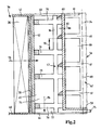
- FIG. 1 is a longitudinal section of a fuel filter 10 of a fuel system of an internal combustion engine of a motor vehicle shown.
- the fuel filter 10 is used to clean the fuel used for the operation of the internal combustion engine, for example diesel fuel. Further, the fuel filter 10 serves to separate water contained in the fuel.
- the fuel filter 10 has a two-part housing 12 with a cup-shaped filter cup 14 and a filter cover 16 which is arranged separably on the filter cup 14. Between the filter cup 14 and the filter cover 16, a ring seal 17 is arranged.
- the lid 16 In the lid 16 is approximately centrally disposed an outlet 18 for the purified fuel, which outside the housing 12 with a in the FIG. 1 Not shown fuel delivery is connected. Inside the housing 12, the outlet nozzle 18 is connected to a drainage space 20 in an interior of a connecting piece 22.
- the connecting piece 22 extends on the inside of the housing 12 facing side of the lid 16 coaxial with a filter axis 24.
- the filter axis 24 In the normal installation position under normal operating conditions of the internal combustion engine, the filter axis 24, as in the FIG. 1 shown, spatially vertical. "Axial”, “radial”, “coaxial” and “circumferential" refer to the filter axis 24 unless otherwise specified.
- the cover 16 Radially outside the connecting piece 22, the cover 16 has an inlet pipe 26 for the fuel to be cleaned, which is connected to an inlet space 28 in the housing 12. Outside the housing 12, the inlet port 26 with a in the FIG. 1 not shown fuel supply for the fuel connected.
- a water outlet pipe 30 is arranged coaxially with the filter axis 24.
- the water drain pipe 30 is connected to a water collecting space 32 at the bottom of the housing 12. Outside of the housing 12, the water discharge nozzle 30 is connected to a water drainage line, not shown, can be derived from the separated from the fuel from the water from the housing 12.
- a water drain valve 34 is arranged with a water level sensor. In the idle state, the water drain valve 34 is closed so that no liquid can escape from the water collection chamber 32 through the water outlet nozzle 30 from the housing 12. Upon reaching a predetermined maximum water level in the water collection chamber 32, the water drain valve 34 opens automatically, so that the separated water can be drained through the water outlet pipe 30.
- a replaceable filter element 36 is arranged in the housing 12.
- the filter element 36 is designed as a round filter element.
- the filter element 36 separates the inlet connection 26 tightly from the outlet connection 18.
- the filter element 36 comprises a star-shaped folded filter medium 38, with which, in particular, particles are filtered out of the fuel to be purified.
- the filter medium 38 has the overall shape of a coaxial circular cylinder jacket.
- the filter medium 38 is tightly connected to a fluid-impermeable terminal end plate 40.
- the filter medium 38 is tightly connected to a Anschlußendcase 42.
- Between the Ranendcase 42 and the complicatendcase 40 extends in an inner space 45 of the filter medium 38 coaxially a skeletal, fluid passages having Mittelrohr 43, which connects the two end plates 40 and 42 stably with each other.
- the final end disk 40 has a coaxial opening 44.
- the opening 44 is surrounded by the central tube 43.
- the opening 44 connects the interior space 45 with the water collecting space 32.
- the end disk 40 On the outside facing the bottom of the filter bowl 14, the end disk 40 has four supporting webs 46 which extend uniformly distributed along an imaginary coaxial circular cylinder jacket.
- the imaginary circular cylinder jacket surrounds the opening 44 and the water outlet nozzle 30.
- the Ranendthrough 42 has a coaxial opening 50.
- the opening 50 is surrounded by two coaxial protrusions which extend in the axial direction on the outer side of the connecting end disk 42.
- the two projections define a receiving groove 52 for an annular insertion web 54 of a water separation unit 56 of the filter element 36.
- a first coaxial coalescing medium 58 Between the radially inner peripheral side of the filter medium 38 and the central tube 43 is a first coaxial coalescing medium 58. Radially within the first coalescing medium 58, a second coaxial coalescing medium 92 follows.
- the coalescing media 58 and 92 are each single-ply fiber webs.
- the first coalescing media 58 is finer, for example, smaller mesh than the second coalescing media 92.
- the coalescing media 58 and 92 are each circumferentially closed and extend between the terminal end disk 42 and the end disk 40.
- the coalescing media 58 and 92 also serve to merge from smallest water droplets contained in the fuel to larger drops of water.
- the water separation unit 56 has a separation medium support body in the form of a support basket 62 with a connection section 64, which also has the insertion web 54, and a separation medium 66.
- the connecting portion 64 is approximately disc-shaped with a coaxial opening into which the connecting piece 22 of the lid 16 protrudes.
- the connection section 64 On its outer side facing the cover 16, the connection section 64 has a coaxial connecting piece 68.
- the connecting piece 68 is bent radially inwards at 90 degrees on its free end side.
- On the radially inner edge of the connecting piece 68 sits a profile ring seal 70.
- In the connecting piece 68 of the connecting piece 22 is inserted so that the connection with the profile ring seal 70 is sealed.
- the water separation unit 56 is inserted axially ahead of the separation medium 66 through the opening 50 of the connection end plate 42.
- the support basket 62 and the separation medium 66 are located in the interior space bounded by the coalescing media 58 and 92, thus also in the interior 45 of the filter medium 38.
- the separation medium 66 consists of a hydrophobic screen fabric. It has the shape of a pipe coaxial with the filter axis 24. It extends from the axial height of the Anschlußendcase 42 to the axial height of the end cap 40.
- the separation medium 68 is circumferentially closed. The axial extent of the separation medium 66 corresponds at least approximately to the axial extent of the filter medium 38 and the coalescing media 58 and 92.
- the peripheral wall of the support basket 62 is constructed like a grid. On its the connection piece 22 associated end face of the support basket 62 is open. The water collection room 32 facing lower end face of the support basket 62 is closed with an end plate 59.
- the end disk 59 is connected to the connection section 64 via four axial struts 60 distributed uniformly in the circumferential direction. In the axial direction approximately centrally between the end plate 59 and the connecting portion 64 a to the filter axis 24 coaxial support ring 61 is arranged, which connects the axial struts 60 together.
- the end plate 59, the axial struts 60 and the support ring 61 are fluid-impermeable.
- the separation medium 66 terminates with radially outer sides of the axial struts 60, the support ring 61 and the end plate 59.
- the separation medium 66 is in a flow direction 80 of the fuel through the separation medium 66 at the level of the radially outer, ie upstream sides of the axial struts 60 and the support ring 61.
- the separation medium 66 may also be in the flow direction 80 behind the radially outer sides of the axial struts 60 and the support ring 61 are located.
- the support basket 62 may be formed on the separation medium 66 or vice versa.
- the support basket 62 and the separation medium 66 may also be connected to each other as separate parts.
- the separation medium 66 and the support basket 62 may also be made of the same material, for example plastic, in one piece, for example cast according to an injection molding process.
- the precipitation gap 74 has the shape of an annular space.
- the precipitation gap 74 is bounded radially outwardly by the coalescing media 58 and 92 and the center tube 43 and radially inward by the separation medium 66.
- the support basket 62 projects beyond the end-side outer surface of the terminal end disk 40 of the filter element 36 in the axial direction by an offset 75.
- an annular outlet opening 77 is realized, which connects the precipitation gap 74 to the water collection chamber 32.
- the staggered arrangement of the terminating end disk 40 and the end disk 59 allows the flow cross section of the precipitating gap 74 to pass continuously into the outlet opening 77 without a bottleneck.
- the radial extent of the precipitation gap 74 has a continuous course in the axial direction.
- the flow cross-section of the precipitation gap 74 for the precipitated water runs perpendicular to the filter axis 24.
- the flow-through cross section of the outlet opening 77 runs obliquely to the filter axis 24.
- the support ring 61 of the support basket 62 is arranged in the axial direction offset to fluid-impermeable peripheral rings 79 of the central tube 43.
- the axial struts 60 of the support basket 62 are circumferentially offset from fluid-impermeable axial struts of the central tube 43, which in the FIG. 1 hidden by the water separation unit 56 are arranged.
- bottlenecks in the precipitation gap 74 are also avoided here.
- annular seal 72 is also arranged, which is supported radially outwardly against the radially inner peripheral side of the filter cup 14.
- the ring seal 72 seals the inlet space 28 against the water collecting space 32.
- the fuel flows through the filter medium 38, indicated by arrows 78, from its crude side radially outside to its clean side radially inside.
- the fuel is freed of particles.
- the filter medium 38 forms a first stage of the overall three-stage fuel filter 10 for cleaning / water separation.
- the particulate-free fuel flows through the coalescing media 58 and 92 from radially outside to inside. In the process, even the smallest water droplets contained in the fuel are captured at the coalescing media 58 and 92 and combined to form larger water droplets.
- the coalescing media 58 and 92 form a second stage for the purification / water separation.
- the fuel flows through the separation medium 66, which forms a third stage for the cleaning / water separation, from radially outside to inside, indicated by arrows 80, and reaches up into the discharge space 20.
- the cleaned and freed of water Fuel leaves the drain space 20 via the outlet port 18, indicated by arrows 82, and is supplied to the fuel discharge.
- the water drain valve 34 As soon as the water level sensor of the water drain valve 34 detects the reaching of the predetermined maximum water level, the water drain valve 34 is automatically opened. The water leaves the water collection chamber 32 through the water outlet pipe 30 and enters the water drain line.
- the lid 16 is removed in the axial direction of the filter cup 14.
- the filter element 36 is then pulled out of the filter bowl 14 in the axial direction.
- the filter element 36 is inserted in the axial direction into the filter cup 14 with the end cap 40. Subsequently, the cover 16 is inserted with the connecting piece 22 in the axial direction on the open side of the filter bowl 14, so that the connecting piece 22 protrudes tightly into the profile ring seal 70.
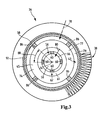
- FIG. 2 and 3 a second embodiment of a filter element 36 is shown. Those elements that are similar to those of the first embodiment FIG. 1 are similar, are provided with the same reference numerals.
- the second embodiment differs from the first embodiment in that the support basket 62 of the water separation unit 56 has a plurality of support rings 61.
- the support rings 61 are offset by an axial offset 90 in the axial direction analogous to the first embodiment to the peripheral rings 79 of the central tube 43. In this way, bottlenecks in the precipitation gap 74 are avoided there.
- the support rings 61 surround the axial struts 60 radially outward.
- the support rings 61 and the axial struts 60 are integrally connected to each other.
- the separation medium 66 is arranged radially inward on the axial struts 60. It is thus located in the flow direction 80 of the fuel through the separation medium 66 behind the upstream, ie radially inner and thus the radially outer sides of the support rings 61 and the axial struts 60.
- the separation medium 66 for the realization of the support basket 62 are sprayed radially outside with plastic.
- the separation medium 66 can alternatively also be located in the flow direction 80 at the level of the radially outer sides of the axial struts 60 or the support rings 61.
- the axial struts 86 of the central tube 43 and the axial struts 60 of the support basket 62 are circumferentially offset by an offset 88 analogous to the first embodiment.
- an offset 88 analogous to the first embodiment.
- the support rings 61 have inclined, in particular rounded, upper sides, as a result of which the drops of water which are retained by the separation medium 66 can flow off particularly well downwards.
- the invention is not limited to a fuel filter 10 of an internal combustion engine of a motor vehicle. Rather, it can also be used in other types of internal combustion engines, for example in industrial engines.
- the fuel filter 10 can also be used for cleaning / separating water from other types of liquid fuel. If a fuel is used whose specific gravity is greater than water, the drops of water increase analogously. In this case, the filter element 36 may be reversed. Likewise, the fuel inlet, the fuel outlet and the water outlet can be arranged appropriately appropriate.
- the filter medium 38 can also be realized as a different type of hollow body, for example also unfolded.
- the coalescing media 58 and 92 may instead of a single-layer nonwoven fabric also consist of a different, even multi-layer coalescing of water droplets coalescing material. It is also possible for more or less than two coalescing media to be provided in succession.
- the support basket 62 projects beyond the frontal outer surface of the complicatendcase 40 of the filter element 36 in the axial direction
- the particularlyendcase 40 may project beyond the support basket 62 by an offset which allows a continuous transition from Aussocilspalt 74 to outlet opening 77.
- the separation medium can also be integrated in the support basket.
- the separation medium can be made in one piece with the support basket.
- axial struts 60 can also be offset relative to corresponding fluid-impermeable axial struts of the central tube 43 in the circumferential direction.
- the filter medium 38, the coalescing media 58 and 92 and / or the separation medium 66 may be realized instead of a hollow cylinder in another form, for example as a hollow cone. Instead of having round base surfaces, they can also be realized with different, for example oval or angular base surfaces.
- the end cap 40 can fit tightly against the radially inner peripheral side of the filter cup 14.
- the separation medium 66 can also be arranged radially outside, surrounding the filter medium 38 and the coalescing media 58 and 92, instead of in the interior 45 of the filter medium 38.
- the fuel to be cleaned can then flow through the filter medium 38 from radially inward to outward.
- the coalescing media 58 and 92 can then preferably also be located radially on the outside and surround the filter medium 38.
- the fuel to be cleaned can be supplied to the top of the filter medium 38 instead of from above also from below.
- the water outlet connection 30 can also be arranged eccentrically in the bottom of the filter bowl 14.
- replaceable filter element 36 may also be provided in the housing 12 fixedly mounted filter element.
Applications Claiming Priority (1)
| Application Number | Priority Date | Filing Date | Title |
|---|---|---|---|
| DE201110120653 DE102011120653A1 (de) | 2011-12-09 | 2011-12-09 | Kraftstofffilter einer Brennkraftmaschine und Filterelement eines Kraftstofffilters |
Publications (3)
| Publication Number | Publication Date |
|---|---|
| EP2602473A2 true EP2602473A2 (fr) | 2013-06-12 |
| EP2602473A3 EP2602473A3 (fr) | 2014-12-03 |
| EP2602473B1 EP2602473B1 (fr) | 2017-01-04 |
Family
ID=47278137
Family Applications (1)
| Application Number | Title | Priority Date | Filing Date |
|---|---|---|---|
| EP12193318.8A Not-in-force EP2602473B1 (fr) | 2011-12-09 | 2012-11-20 | Filtre de carburant d'un moteur à combustion interne et élément de filtre d'un filtre de carburant |
Country Status (4)
| Country | Link |
|---|---|
| US (2) | US9121376B2 (fr) |
| EP (1) | EP2602473B1 (fr) |
| CN (1) | CN103161630B (fr) |
| DE (1) | DE102011120653A1 (fr) |
Cited By (6)
| Publication number | Priority date | Publication date | Assignee | Title |
|---|---|---|---|---|
| WO2015018785A1 (fr) * | 2013-08-05 | 2015-02-12 | Mann+Hummel Gmbh | Élément filtrant pour un filtre de liquide |
| WO2015018779A1 (fr) * | 2013-08-05 | 2015-02-12 | Mann+Hummel Gmbh | Crible séparateur d'eau pour un élément filtrant dans un filtre de liquide |
| WO2015135667A1 (fr) * | 2014-03-12 | 2015-09-17 | Mann+Hummel Gmbh | Élément de filtre en forme de grille pour un élément de filtre à carburant comprenant une séparation multi-étapes de l'eau et élément de filtre à carburant |
| DE102014206954A1 (de) | 2014-04-10 | 2015-10-15 | Mahle International Gmbh | Kraftstofffilter einer Brennkraftmaschine |
| DE102016010778A1 (de) | 2016-09-08 | 2018-03-08 | Mann+Hummel Gmbh | Trennmodul, Wasserabscheidevorrichtung mit einem Trennmodul und Filtersystem mit einer Wasserabscheidevorrichtung |
| CN112243388A (zh) * | 2018-06-13 | 2021-01-19 | 卡特彼勒公司 | 用于在一定坡度上检测的带腔燃料包水传感器 |
Families Citing this family (18)
| Publication number | Priority date | Publication date | Assignee | Title |
|---|---|---|---|---|
| DE102011120641A1 (de) * | 2011-12-09 | 2013-06-13 | Mann + Hummel Gmbh | Kraftstofffilter einer Brennkraftmaschine und Filterelement eines Kraftstofffilters |
| DE102013016976A1 (de) * | 2013-10-14 | 2015-04-16 | Mann + Hummel Gmbh | Filterelement und Filtersystem für ein Flüssigmedium, insbesondere Dieselkraftstoff |
| US9957932B2 (en) * | 2014-04-11 | 2018-05-01 | Illinois Tool Works Inc. | Filter assembly for separating water from fuel |
| DE102015003915A1 (de) * | 2014-04-28 | 2015-11-12 | Mann + Hummel Gmbh | Abscheideelement einer Abscheidevorrichtung zur Abscheidung wenigstens eines fluiden Mediums aus einem zu behandelnden Fluid und Abscheidevorrichtung |
| EP3221025B1 (fr) * | 2014-11-20 | 2021-09-29 | MANN+HUMMEL GmbH | Élément filtre séparant de l'eau côté pur et comprenant une liaison à baïonnette et filtre à carburant comprenant un élément filtre de ce type |
| DE102015203687A1 (de) | 2015-03-02 | 2016-09-08 | Mahle International Gmbh | Kraftstofffiltereinrichtung |
| DE102015003163A1 (de) * | 2015-03-13 | 2016-09-29 | Mann + Hummel Gmbh | Kraftstofffiltereinsatz und Kraftstofffilter mit einem Vor- und einem Hauptfilterelement sowie mit einer Wasserabscheideeinheit |
| KR101684126B1 (ko) | 2015-06-12 | 2016-12-08 | 현대자동차주식회사 | 자동차용 연료필터 |
| DE102015010082A1 (de) | 2015-08-07 | 2017-02-09 | Mann+Hummel Gmbh | Wasserabscheideelement |
| DE102015013351A1 (de) | 2015-10-15 | 2017-04-20 | Mann + Hummel Gmbh | Koaleszenzelement und Filterelement mit einem Koaleszenzelement |
| JP6390681B2 (ja) * | 2016-03-14 | 2018-09-19 | 株式会社デンソー | 燃料供給装置 |
| DE102017007270A1 (de) * | 2017-08-01 | 2019-02-07 | Hydac Fluidcarecenter Gmbh | Filterelement |
| DE102018205069A1 (de) * | 2018-04-04 | 2019-10-10 | Mahle International Gmbh | Filtereinrichtung |
| DE102018108986A1 (de) * | 2018-04-16 | 2019-10-17 | FAUDI Aviation GmbH | Filterelement, Koaleszenzabscheider und Verfahren zu deren Herstellung sowie deren Verwendung |
| CN109340004A (zh) * | 2018-11-14 | 2019-02-15 | 广西华原过滤系统股份有限公司 | 一种三级油水分离器 |
| DE102018133569A1 (de) * | 2018-12-21 | 2020-06-25 | Hengst Se | Filtereinsatz für einen Kraftstofffilter mit dreistufiger Filtration |
| CN115263631B (zh) * | 2022-06-09 | 2023-08-18 | 上海汽车集团股份有限公司 | 一种正压集成式燃油滤清器 |
| CN114992018B (zh) * | 2022-06-20 | 2023-12-19 | 上海弗列加滤清器有限公司 | 一种脱硫滤清器和车辆 |
Citations (1)
| Publication number | Priority date | Publication date | Assignee | Title |
|---|---|---|---|---|
| US20090250402A1 (en) | 2006-06-20 | 2009-10-08 | Cummins Filtration Ip Inc. | Replaceable filter elements including plural filter media and related filtration systems, techniques and methods |
Family Cites Families (8)
| Publication number | Priority date | Publication date | Assignee | Title |
|---|---|---|---|---|
| US2864505A (en) * | 1956-09-07 | 1958-12-16 | Bendix Aviat Corp | Vertical two stage demulsifier filter assembly |
| US3187895A (en) * | 1963-01-23 | 1965-06-08 | Pall Corp | Fuel-water separator |
| US4372847A (en) * | 1980-06-23 | 1983-02-08 | Chicago Rawhide Manufacturing Company | Fuel filter assembly and cartridge |
| US4477345A (en) * | 1983-01-10 | 1984-10-16 | Stant Inc. | Filter separator with heater |
| DE10123190A1 (de) * | 2001-05-12 | 2002-11-14 | Mahle Filtersysteme Gmbh | Kraftstofffilter mit wasserabscheidenden Mitteln |
| CN102802755B (zh) * | 2010-03-04 | 2014-12-10 | Hydac过滤技术有限公司 | 过滤装置以及为此设置的过滤元件 |
| CN201943861U (zh) * | 2011-02-15 | 2011-08-24 | 南充市攀峰滤清器有限公司 | 无公害双级油水分离柴油滤清器 |
| CN102258897B (zh) * | 2011-05-05 | 2012-12-26 | 合肥威尔燃油系统有限责任公司 | 燃油滤清器 |
-
2011
- 2011-12-09 DE DE201110120653 patent/DE102011120653A1/de active Granted
-
2012
- 2012-11-20 EP EP12193318.8A patent/EP2602473B1/fr not_active Not-in-force
- 2012-12-07 CN CN201210598398.4A patent/CN103161630B/zh active Active
- 2012-12-10 US US13/709,207 patent/US9121376B2/en active Active
-
2015
- 2015-08-31 US US14/840,847 patent/US10018166B2/en active Active
Patent Citations (1)
| Publication number | Priority date | Publication date | Assignee | Title |
|---|---|---|---|---|
| US20090250402A1 (en) | 2006-06-20 | 2009-10-08 | Cummins Filtration Ip Inc. | Replaceable filter elements including plural filter media and related filtration systems, techniques and methods |
Cited By (8)
| Publication number | Priority date | Publication date | Assignee | Title |
|---|---|---|---|---|
| WO2015018785A1 (fr) * | 2013-08-05 | 2015-02-12 | Mann+Hummel Gmbh | Élément filtrant pour un filtre de liquide |
| WO2015018779A1 (fr) * | 2013-08-05 | 2015-02-12 | Mann+Hummel Gmbh | Crible séparateur d'eau pour un élément filtrant dans un filtre de liquide |
| US20160151723A1 (en) * | 2013-08-05 | 2016-06-02 | Mann+Hummel Gmbh | Water separating screen for a filter element in a liquid filter |
| US9962637B2 (en) | 2013-08-05 | 2018-05-08 | Mann+Hummel Gmbh | Filter element for a liquid filter |
| WO2015135667A1 (fr) * | 2014-03-12 | 2015-09-17 | Mann+Hummel Gmbh | Élément de filtre en forme de grille pour un élément de filtre à carburant comprenant une séparation multi-étapes de l'eau et élément de filtre à carburant |
| DE102014206954A1 (de) | 2014-04-10 | 2015-10-15 | Mahle International Gmbh | Kraftstofffilter einer Brennkraftmaschine |
| DE102016010778A1 (de) | 2016-09-08 | 2018-03-08 | Mann+Hummel Gmbh | Trennmodul, Wasserabscheidevorrichtung mit einem Trennmodul und Filtersystem mit einer Wasserabscheidevorrichtung |
| CN112243388A (zh) * | 2018-06-13 | 2021-01-19 | 卡特彼勒公司 | 用于在一定坡度上检测的带腔燃料包水传感器 |
Also Published As
| Publication number | Publication date |
|---|---|
| CN103161630A (zh) | 2013-06-19 |
| US10018166B2 (en) | 2018-07-10 |
| US20160010605A1 (en) | 2016-01-14 |
| EP2602473A3 (fr) | 2014-12-03 |
| CN103161630B (zh) | 2017-05-10 |
| EP2602473B1 (fr) | 2017-01-04 |
| US20130146523A1 (en) | 2013-06-13 |
| DE102011120653A1 (de) | 2013-06-13 |
| US9121376B2 (en) | 2015-09-01 |
Similar Documents
| Publication | Publication Date | Title |
|---|---|---|
| EP2602473B1 (fr) | Filtre de carburant d'un moteur à combustion interne et élément de filtre d'un filtre de carburant | |
| EP2602472B1 (fr) | Filtre de carburant d'un moteur à combustion interne et élément de filtre d'un filtre de carburant | |
| EP2788099B1 (fr) | Filtre à carburant d'un moteur à combustion interne et élément filtrant d'un filtre à carburant | |
| EP2788612B1 (fr) | Filtre à carburant d'un moteur à combustion interne et élément filtrant d'un filtre à carburant | |
| EP2663378B1 (fr) | Dispositif de filtration | |
| DE102015003915A1 (de) | Abscheideelement einer Abscheidevorrichtung zur Abscheidung wenigstens eines fluiden Mediums aus einem zu behandelnden Fluid und Abscheidevorrichtung | |
| EP2145099B1 (fr) | Dispositif d'amenée de carburant destiné en particulier à un moteur à combustion interne | |
| DE102013012918B4 (de) | Flüssigkeitsfilter und Filterelement, insbesondere für Kraftstoff | |
| EP2049222B1 (fr) | Dispositif de filtration | |
| EP3140020B1 (fr) | Élément de coalescence d'un dispositif de séparation d'eau et dispositif de séparation d'eau | |
| DE102009018000B4 (de) | Abscheider zum Abscheiden von Flüssigkeitströpfchen aus einem Aerosol | |
| WO2014009060A1 (fr) | Dispositif séparateur d'eau, élément filtre d'un filtre à carburant, et filtre à carburant correspondant | |
| DE102014000903A1 (de) | Filter- und Koaleszenzelement sowie zugehörige Medienlage und Filtervorrichtung | |
| WO2015018779A1 (fr) | Crible séparateur d'eau pour un élément filtrant dans un filtre de liquide | |
| EP3658252B1 (fr) | Filtre à liquide et système filtrant de réservoir pourvu d'un filtre à liquide | |
| EP3661621B1 (fr) | Élément filtrant | |
| DE202008002927U1 (de) | Flüssigkeitsfilter, insbesondere für Kraftstoff | |
| DE202013011849U1 (de) | Filterelement | |
| DE102012219885B3 (de) | Flüssigkeitsfilter | |
| DE102012024349B4 (de) | Filter zur Filtrierung von Flüssigkeiten und Filterelement eines derartigen Filters | |
| DE102014006259B4 (de) | Koaleszenzelement eines Wasserabscheiders für Kraftstoff und Wasserabscheider | |
| DE102013018199B4 (de) | Flüssigkeitsfilter, insbesondere für Kraftstoff | |
| DE102022106035A1 (de) | Abscheidevorrichtung, Impaktorabscheid-Element und Gasstromreinigungsverfahren | |
| EP3695893A1 (fr) | Dispositif filtrant | |
| DE102015000942A1 (de) | Filterelement, Filtervorrichtung und Filtergehäuse einer Filtervorrichtung |
Legal Events
| Date | Code | Title | Description |
|---|---|---|---|
| PUAI | Public reference made under article 153(3) epc to a published international application that has entered the european phase |
Free format text: ORIGINAL CODE: 0009012 |
|
| AK | Designated contracting states |
Kind code of ref document: A2 Designated state(s): AL AT BE BG CH CY CZ DE DK EE ES FI FR GB GR HR HU IE IS IT LI LT LU LV MC MK MT NL NO PL PT RO RS SE SI SK SM TR |
|
| AX | Request for extension of the european patent |
Extension state: BA ME |
|
| PUAL | Search report despatched |
Free format text: ORIGINAL CODE: 0009013 |
|
| AK | Designated contracting states |
Kind code of ref document: A3 Designated state(s): AL AT BE BG CH CY CZ DE DK EE ES FI FR GB GR HR HU IE IS IT LI LT LU LV MC MK MT NL NO PL PT RO RS SE SI SK SM TR |
|
| AX | Request for extension of the european patent |
Extension state: BA ME |
|
| 17P | Request for examination filed |
Effective date: 20150526 |
|
| RBV | Designated contracting states (corrected) |
Designated state(s): AL AT BE BG CH CY CZ DE DK EE ES FI FR GB GR HR HU IE IS IT LI LT LU LV MC MK MT NL NO PL PT RO RS SE SI SK SM TR |
|
| 17Q | First examination report despatched |
Effective date: 20151103 |
|
| GRAP | Despatch of communication of intention to grant a patent |
Free format text: ORIGINAL CODE: EPIDOSNIGR1 |
|
| RIC1 | Information provided on ipc code assigned before grant |
Ipc: F02M 37/22 20060101AFI20160701BHEP Ipc: B01D 36/00 20060101ALI20160701BHEP |
|
| INTG | Intention to grant announced |
Effective date: 20160726 |
|
| GRAS | Grant fee paid |
Free format text: ORIGINAL CODE: EPIDOSNIGR3 |
|
| GRAA | (expected) grant |
Free format text: ORIGINAL CODE: 0009210 |
|
| AK | Designated contracting states |
Kind code of ref document: B1 Designated state(s): AL AT BE BG CH CY CZ DE DK EE ES FI FR GB GR HR HU IE IS IT LI LT LU LV MC MK MT NL NO PL PT RO RS SE SI SK SM TR |
|
| REG | Reference to a national code |
Ref country code: GB Ref legal event code: FG4D Free format text: NOT ENGLISH |
|
| REG | Reference to a national code |
Ref country code: CH Ref legal event code: EP |
|
| REG | Reference to a national code |
Ref country code: AT Ref legal event code: REF Ref document number: 859484 Country of ref document: AT Kind code of ref document: T Effective date: 20170115 |
|
| REG | Reference to a national code |
Ref country code: IE Ref legal event code: FG4D Free format text: LANGUAGE OF EP DOCUMENT: GERMAN |
|
| REG | Reference to a national code |
Ref country code: DE Ref legal event code: R096 Ref document number: 502012009200 Country of ref document: DE |
|
| REG | Reference to a national code |
Ref country code: LT Ref legal event code: MG4D Ref country code: NL Ref legal event code: MP Effective date: 20170104 |
|
| PG25 | Lapsed in a contracting state [announced via postgrant information from national office to epo] |
Ref country code: NL Free format text: LAPSE BECAUSE OF FAILURE TO SUBMIT A TRANSLATION OF THE DESCRIPTION OR TO PAY THE FEE WITHIN THE PRESCRIBED TIME-LIMIT Effective date: 20170104 |
|
| PG25 | Lapsed in a contracting state [announced via postgrant information from national office to epo] |
Ref country code: GR Free format text: LAPSE BECAUSE OF FAILURE TO SUBMIT A TRANSLATION OF THE DESCRIPTION OR TO PAY THE FEE WITHIN THE PRESCRIBED TIME-LIMIT Effective date: 20170405 Ref country code: FI Free format text: LAPSE BECAUSE OF FAILURE TO SUBMIT A TRANSLATION OF THE DESCRIPTION OR TO PAY THE FEE WITHIN THE PRESCRIBED TIME-LIMIT Effective date: 20170104 Ref country code: IS Free format text: LAPSE BECAUSE OF FAILURE TO SUBMIT A TRANSLATION OF THE DESCRIPTION OR TO PAY THE FEE WITHIN THE PRESCRIBED TIME-LIMIT Effective date: 20170504 Ref country code: NO Free format text: LAPSE BECAUSE OF FAILURE TO SUBMIT A TRANSLATION OF THE DESCRIPTION OR TO PAY THE FEE WITHIN THE PRESCRIBED TIME-LIMIT Effective date: 20170404 Ref country code: LT Free format text: LAPSE BECAUSE OF FAILURE TO SUBMIT A TRANSLATION OF THE DESCRIPTION OR TO PAY THE FEE WITHIN THE PRESCRIBED TIME-LIMIT Effective date: 20170104 Ref country code: HR Free format text: LAPSE BECAUSE OF FAILURE TO SUBMIT A TRANSLATION OF THE DESCRIPTION OR TO PAY THE FEE WITHIN THE PRESCRIBED TIME-LIMIT Effective date: 20170104 |
|
| PG25 | Lapsed in a contracting state [announced via postgrant information from national office to epo] |
Ref country code: ES Free format text: LAPSE BECAUSE OF FAILURE TO SUBMIT A TRANSLATION OF THE DESCRIPTION OR TO PAY THE FEE WITHIN THE PRESCRIBED TIME-LIMIT Effective date: 20170104 Ref country code: SE Free format text: LAPSE BECAUSE OF FAILURE TO SUBMIT A TRANSLATION OF THE DESCRIPTION OR TO PAY THE FEE WITHIN THE PRESCRIBED TIME-LIMIT Effective date: 20170104 Ref country code: BG Free format text: LAPSE BECAUSE OF FAILURE TO SUBMIT A TRANSLATION OF THE DESCRIPTION OR TO PAY THE FEE WITHIN THE PRESCRIBED TIME-LIMIT Effective date: 20170404 Ref country code: RS Free format text: LAPSE BECAUSE OF FAILURE TO SUBMIT A TRANSLATION OF THE DESCRIPTION OR TO PAY THE FEE WITHIN THE PRESCRIBED TIME-LIMIT Effective date: 20170104 Ref country code: PL Free format text: LAPSE BECAUSE OF FAILURE TO SUBMIT A TRANSLATION OF THE DESCRIPTION OR TO PAY THE FEE WITHIN THE PRESCRIBED TIME-LIMIT Effective date: 20170104 Ref country code: PT Free format text: LAPSE BECAUSE OF FAILURE TO SUBMIT A TRANSLATION OF THE DESCRIPTION OR TO PAY THE FEE WITHIN THE PRESCRIBED TIME-LIMIT Effective date: 20170504 Ref country code: LV Free format text: LAPSE BECAUSE OF FAILURE TO SUBMIT A TRANSLATION OF THE DESCRIPTION OR TO PAY THE FEE WITHIN THE PRESCRIBED TIME-LIMIT Effective date: 20170104 |
|
| REG | Reference to a national code |
Ref country code: DE Ref legal event code: R097 Ref document number: 502012009200 Country of ref document: DE |
|
| PG25 | Lapsed in a contracting state [announced via postgrant information from national office to epo] |
Ref country code: EE Free format text: LAPSE BECAUSE OF FAILURE TO SUBMIT A TRANSLATION OF THE DESCRIPTION OR TO PAY THE FEE WITHIN THE PRESCRIBED TIME-LIMIT Effective date: 20170104 Ref country code: CZ Free format text: LAPSE BECAUSE OF FAILURE TO SUBMIT A TRANSLATION OF THE DESCRIPTION OR TO PAY THE FEE WITHIN THE PRESCRIBED TIME-LIMIT Effective date: 20170104 Ref country code: SK Free format text: LAPSE BECAUSE OF FAILURE TO SUBMIT A TRANSLATION OF THE DESCRIPTION OR TO PAY THE FEE WITHIN THE PRESCRIBED TIME-LIMIT Effective date: 20170104 Ref country code: RO Free format text: LAPSE BECAUSE OF FAILURE TO SUBMIT A TRANSLATION OF THE DESCRIPTION OR TO PAY THE FEE WITHIN THE PRESCRIBED TIME-LIMIT Effective date: 20170104 Ref country code: IT Free format text: LAPSE BECAUSE OF FAILURE TO SUBMIT A TRANSLATION OF THE DESCRIPTION OR TO PAY THE FEE WITHIN THE PRESCRIBED TIME-LIMIT Effective date: 20170104 |
|
| PLBE | No opposition filed within time limit |
Free format text: ORIGINAL CODE: 0009261 |
|
| STAA | Information on the status of an ep patent application or granted ep patent |
Free format text: STATUS: NO OPPOSITION FILED WITHIN TIME LIMIT |
|
| REG | Reference to a national code |
Ref country code: FR Ref legal event code: PLFP Year of fee payment: 6 |
|
| PG25 | Lapsed in a contracting state [announced via postgrant information from national office to epo] |
Ref country code: SM Free format text: LAPSE BECAUSE OF FAILURE TO SUBMIT A TRANSLATION OF THE DESCRIPTION OR TO PAY THE FEE WITHIN THE PRESCRIBED TIME-LIMIT Effective date: 20170104 Ref country code: DK Free format text: LAPSE BECAUSE OF FAILURE TO SUBMIT A TRANSLATION OF THE DESCRIPTION OR TO PAY THE FEE WITHIN THE PRESCRIBED TIME-LIMIT Effective date: 20170104 |
|
| 26N | No opposition filed |
Effective date: 20171005 |
|
| PGFP | Annual fee paid to national office [announced via postgrant information from national office to epo] |
Ref country code: DE Payment date: 20171121 Year of fee payment: 6 Ref country code: FR Payment date: 20171121 Year of fee payment: 6 |
|
| PG25 | Lapsed in a contracting state [announced via postgrant information from national office to epo] |
Ref country code: SI Free format text: LAPSE BECAUSE OF FAILURE TO SUBMIT A TRANSLATION OF THE DESCRIPTION OR TO PAY THE FEE WITHIN THE PRESCRIBED TIME-LIMIT Effective date: 20170104 |
|
| PG25 | Lapsed in a contracting state [announced via postgrant information from national office to epo] |
Ref country code: MC Free format text: LAPSE BECAUSE OF FAILURE TO SUBMIT A TRANSLATION OF THE DESCRIPTION OR TO PAY THE FEE WITHIN THE PRESCRIBED TIME-LIMIT Effective date: 20170104 |
|
| GBPC | Gb: european patent ceased through non-payment of renewal fee |
Effective date: 20171120 |
|
| PG25 | Lapsed in a contracting state [announced via postgrant information from national office to epo] |
Ref country code: CH Free format text: LAPSE BECAUSE OF NON-PAYMENT OF DUE FEES Effective date: 20171130 Ref country code: LI Free format text: LAPSE BECAUSE OF NON-PAYMENT OF DUE FEES Effective date: 20171130 |
|
| PG25 | Lapsed in a contracting state [announced via postgrant information from national office to epo] |
Ref country code: LU Free format text: LAPSE BECAUSE OF NON-PAYMENT OF DUE FEES Effective date: 20171120 |
|
| REG | Reference to a national code |
Ref country code: BE Ref legal event code: MM Effective date: 20171130 |
|
| REG | Reference to a national code |
Ref country code: IE Ref legal event code: MM4A |
|
| PG25 | Lapsed in a contracting state [announced via postgrant information from national office to epo] |
Ref country code: MT Free format text: LAPSE BECAUSE OF FAILURE TO SUBMIT A TRANSLATION OF THE DESCRIPTION OR TO PAY THE FEE WITHIN THE PRESCRIBED TIME-LIMIT Effective date: 20170104 |
|
| PG25 | Lapsed in a contracting state [announced via postgrant information from national office to epo] |
Ref country code: IE Free format text: LAPSE BECAUSE OF NON-PAYMENT OF DUE FEES Effective date: 20171120 |
|
| PG25 | Lapsed in a contracting state [announced via postgrant information from national office to epo] |
Ref country code: GB Free format text: LAPSE BECAUSE OF NON-PAYMENT OF DUE FEES Effective date: 20171120 Ref country code: BE Free format text: LAPSE BECAUSE OF NON-PAYMENT OF DUE FEES Effective date: 20171130 |
|
| REG | Reference to a national code |
Ref country code: AT Ref legal event code: MM01 Ref document number: 859484 Country of ref document: AT Kind code of ref document: T Effective date: 20171120 |
|
| PG25 | Lapsed in a contracting state [announced via postgrant information from national office to epo] |
Ref country code: AT Free format text: LAPSE BECAUSE OF NON-PAYMENT OF DUE FEES Effective date: 20171120 |
|
| REG | Reference to a national code |
Ref country code: DE Ref legal event code: R119 Ref document number: 502012009200 Country of ref document: DE |
|
| PG25 | Lapsed in a contracting state [announced via postgrant information from national office to epo] |
Ref country code: HU Free format text: LAPSE BECAUSE OF FAILURE TO SUBMIT A TRANSLATION OF THE DESCRIPTION OR TO PAY THE FEE WITHIN THE PRESCRIBED TIME-LIMIT; INVALID AB INITIO Effective date: 20121120 |
|
| PG25 | Lapsed in a contracting state [announced via postgrant information from national office to epo] |
Ref country code: DE Free format text: LAPSE BECAUSE OF NON-PAYMENT OF DUE FEES Effective date: 20190601 Ref country code: CY Free format text: LAPSE BECAUSE OF NON-PAYMENT OF DUE FEES Effective date: 20170104 Ref country code: FR Free format text: LAPSE BECAUSE OF NON-PAYMENT OF DUE FEES Effective date: 20181130 |
|
| PG25 | Lapsed in a contracting state [announced via postgrant information from national office to epo] |
Ref country code: MK Free format text: LAPSE BECAUSE OF FAILURE TO SUBMIT A TRANSLATION OF THE DESCRIPTION OR TO PAY THE FEE WITHIN THE PRESCRIBED TIME-LIMIT Effective date: 20170104 |
|
| PG25 | Lapsed in a contracting state [announced via postgrant information from national office to epo] |
Ref country code: TR Free format text: LAPSE BECAUSE OF FAILURE TO SUBMIT A TRANSLATION OF THE DESCRIPTION OR TO PAY THE FEE WITHIN THE PRESCRIBED TIME-LIMIT Effective date: 20170104 |
|
| PG25 | Lapsed in a contracting state [announced via postgrant information from national office to epo] |
Ref country code: AL Free format text: LAPSE BECAUSE OF FAILURE TO SUBMIT A TRANSLATION OF THE DESCRIPTION OR TO PAY THE FEE WITHIN THE PRESCRIBED TIME-LIMIT Effective date: 20170104 |