EP2602402A2 - Dismountable facade scaffold - Google Patents
Dismountable facade scaffold Download PDFInfo
- Publication number
- EP2602402A2 EP2602402A2 EP12008094.0A EP12008094A EP2602402A2 EP 2602402 A2 EP2602402 A2 EP 2602402A2 EP 12008094 A EP12008094 A EP 12008094A EP 2602402 A2 EP2602402 A2 EP 2602402A2
- Authority
- EP
- European Patent Office
- Prior art keywords
- shaped
- scaffold
- vertical
- base frame
- scaffolding
- Prior art date
- Legal status (The legal status is an assumption and is not a legal conclusion. Google has not performed a legal analysis and makes no representation as to the accuracy of the status listed.)
- Granted
Links
- 238000000034 method Methods 0.000 claims abstract description 7
- 210000003127 knee Anatomy 0.000 claims description 6
- 230000015572 biosynthetic process Effects 0.000 claims description 4
- 238000009434 installation Methods 0.000 claims description 2
- 238000010276 construction Methods 0.000 description 14
- VOXZDWNPVJITMN-ZBRFXRBCSA-N 17β-estradiol Chemical compound OC1=CC=C2[C@H]3CC[C@](C)([C@H](CC4)O)[C@@H]4[C@@H]3CCC2=C1 VOXZDWNPVJITMN-ZBRFXRBCSA-N 0.000 description 1
- 230000006978 adaptation Effects 0.000 description 1
- 230000000454 anti-cipatory effect Effects 0.000 description 1
- 230000001419 dependent effect Effects 0.000 description 1
- 238000011161 development Methods 0.000 description 1
- 230000018109 developmental process Effects 0.000 description 1
- 238000009408 flooring Methods 0.000 description 1
- 230000000284 resting effect Effects 0.000 description 1
- 239000002689 soil Substances 0.000 description 1
Images


Classifications
-
- E—FIXED CONSTRUCTIONS
- E04—BUILDING
- E04G—SCAFFOLDING; FORMS; SHUTTERING; BUILDING IMPLEMENTS OR AIDS, OR THEIR USE; HANDLING BUILDING MATERIALS ON THE SITE; REPAIRING, BREAKING-UP OR OTHER WORK ON EXISTING BUILDINGS
- E04G1/00—Scaffolds primarily resting on the ground
- E04G1/14—Comprising essentially pre-assembled two-dimensional frame-like elements, e.g. of rods in L- or H-shape, with or without bracing
-
- E—FIXED CONSTRUCTIONS
- E04—BUILDING
- E04G—SCAFFOLDING; FORMS; SHUTTERING; BUILDING IMPLEMENTS OR AIDS, OR THEIR USE; HANDLING BUILDING MATERIALS ON THE SITE; REPAIRING, BREAKING-UP OR OTHER WORK ON EXISTING BUILDINGS
- E04G1/00—Scaffolds primarily resting on the ground
- E04G1/15—Scaffolds primarily resting on the ground essentially comprising special means for supporting or forming platforms; Platforms
-
- E—FIXED CONSTRUCTIONS
- E04—BUILDING
- E04G—SCAFFOLDING; FORMS; SHUTTERING; BUILDING IMPLEMENTS OR AIDS, OR THEIR USE; HANDLING BUILDING MATERIALS ON THE SITE; REPAIRING, BREAKING-UP OR OTHER WORK ON EXISTING BUILDINGS
- E04G5/00—Component parts or accessories for scaffolds
- E04G5/14—Railings
- E04G5/147—Railings specially adapted for mounting prior to the mounting of the platform
-
- E—FIXED CONSTRUCTIONS
- E04—BUILDING
- E04G—SCAFFOLDING; FORMS; SHUTTERING; BUILDING IMPLEMENTS OR AIDS, OR THEIR USE; HANDLING BUILDING MATERIALS ON THE SITE; REPAIRING, BREAKING-UP OR OTHER WORK ON EXISTING BUILDINGS
- E04G1/00—Scaffolds primarily resting on the ground
- E04G1/15—Scaffolds primarily resting on the ground essentially comprising special means for supporting or forming platforms; Platforms
- E04G2001/158—Platforms supported by spigots which engage through holes in the platform
Abstract
Description
Die Erfindung betrifft ein zerlegbares Fassadengerüst eines Fassadengerüstes.The invention relates to a dismountable facade scaffolding of a facade scaffold.
Aus dem Stand der Technik sind zerlegbare Fassadengerüste bekannt, wie z. B. das Fassadengerüst plettac SL 70 der Firma ALTRAD plettac assco GmbH - Plettenberg, wobei das Fassadengerüst aus seitlichem Rahmenelementen, Verbindungsstreben, wie z. B. Diagonalstreben bzw. Geländer und/oder Kniestreben sowie im Grundrahmen eingelegten Bodenelementen gebildet ist. Die seitlichen Rahmenelemente, auch bekannt als Vertikalrahmen, sind vorzugsweise als geschlossene Rahmenelemente ausgebildet. Zur Absicherung von Personen wird das Fassadengerüst in den Arbeitsebenen mit einer Geländerstrebe gesichert, welche beim Aufbau einer neuen Arbeitsebene von dieser Ebene aus montiert wird. Dies birgt bis zur abgeschlossenen Gerüstmontage die Gefahr von Abstürzen. Zum Aufbau einer Arbeitsebene sind die seitlichen Vertikalrahmen vorzugsweise als geschlossene Rahmenelemente ausgebildet, weisen eine daran montierte Geländerstrebe auf und werden als zusätzliche Bauteile für einen sicherheitsrelevanten Aufbau einer nachfolgenden Arbeitsebene eingesetzt. Ein derartiger Gerüstaufbau ist mit einem erheblichen Aufwand verbunden.From the prior art demountable facade scaffolds are known, such. B. the facade scaffold plettac SL 70 ALTRAD company plettac assco GmbH - Plettenberg, the facade scaffold from lateral frame elements, connecting struts such. B. diagonal struts or railing and / or knee straps and inserted in the base frame bottom elements is formed. The lateral frame elements, also known as vertical frames, are preferably designed as closed frame elements. To protect people, the facade scaffolding is secured in the working levels with a railing strut, which is mounted from this level when constructing a new working level. This holds until the completion of scaffolding assembly the risk of crashes. To construct a working plane, the lateral vertical frames are preferably designed as closed frame elements, have a railing strut mounted thereon and are used as additional components for a safety-relevant construction of a subsequent working plane. Such a framework construction is associated with a considerable effort.
Aus diesem Grund hat sich die Erfindung die Aufgabe gestellt, ein zerlegbares Fassadengerüst vorzuschlagen, welches die Flexibilität und Sicherheit im Aufbau verbessert.For this reason, the invention has set itself the task of proposing a collapsible facade scaffold, which improves the flexibility and safety in construction.
Die Aufgabe wird, ausgehend von dem eingangs genannten Stand der Technik, durch die Merkmale des Anspruchs 1 bzw. durch die Merkmale des Anspruchs 2 und 10 gelöst.The object is achieved on the basis of the aforementioned prior art, by the features of
Durch die in den abhängigen Ansprüchen genannten Maßnahmen sind vorteilhafte Ausführungsbeispiele und Weiterbildungen der Erfindung gegeben.The measures mentioned in the dependent claims advantageous embodiments and further developments of the invention are given.
Dementsprechend erstreckt sich ein zerlegbares Fassadengerüst über eine Grundebene und mindestens einer Arbeitsebene, die zwischen zwei seitlichen Vertikalträgern angeordnet sind, wobei das Fassadengerüst nachfolgende Gerüstelemente umfasst:
- ● Einen Grundrahmen in der Grundebene aus mindestens zwei parallel zueinander angeordneten geschlossenen Vertikalrahmen;
- ● Am Grundrahmen angeordnete, vorzugsweise höheneinstellbare Fußstützen;
- ● Mindestens eine Diagonalstrebe und eine horizontale Verbindungsstrebe am Grundrahmen;
- ● Ein im oberen Endbereich des Grundrahmens angeordnetes Bodenelement zur Bildung der ersten Arbeitsebene;
- ● Mindestens eine auf der zur Fassadenfläche abgewandten Gerüstseite angeordneten Geländerstrebe, vorzugsweise ab der ersten Arbeitsebene, wobei
- die Bestandteile der Vertikalträger aus unterschiedlichen Gerüstelementen gebildet sind, welche eine U-, L- oder T-Form aufweisen und im Wesentlichen zu geschlossenen Vertikalrahmen kombinierbar sind,
- das T-förmige Gerüstelement einen Querriegel zur
- Aufnahme von Bodenelementen und mindestens eine Anlenkung für eine Geländerstrebe aufweist und die Geländerstrebe der nächst folgenden Arbeitsebene an der Anlenkung bei der Montage des T-förmigen Gerüstelements anbringbar ist,
- das L-förmige Gerüstelement einen Querriegel zur obenseitigen Sicherung der Bodenelemente in einer neu gebildeten Arbeitsebene umfasst.
- ● A base frame in the ground plane consisting of at least two closed vertical frames arranged parallel to each other;
- ● Footrests arranged on the base frame, preferably adjustable in height;
- ● At least one diagonal strut and one horizontal connecting strut on the base frame;
- ● A bottom element arranged in the upper end region of the base frame for forming the first working plane;
- ● At least one on the side facing away from the facade surface frame side railing strut, preferably from the first working level, wherein
- the components of the vertical support are formed from different structural elements which have a U, L or T shape and can be combined substantially to form closed vertical frames,
- the T-shaped scaffolding element a crossbar for
- Containing soil elements and at least one linkage for a railing strut and the Railing strut of the next following working plane can be attached to the linkage during assembly of the T-shaped scaffold element,
- the L-shaped scaffolding element comprises a cross bar for securing the floor elements in a newly formed working plane on top.
Der Vorteil gegenüber dem aus dem Stand der Technik bekannten Fassadengerüst ist ein Aufbau des Fassadengerüstes mit verbesserter Sicherheit ohne zusätzliche Bauteile. Die "vorlaufende" Geländerstrebe wird im normalen Gerüstaufbau montiert und erfordert keinen zusätzlichen Montageaufwand.The advantage over the known from the prior art facade scaffolding is a structure of the facade scaffold with improved safety without additional components. The "leading" railing strut is mounted in the normal framework construction and requires no additional installation effort.
Zusätzlich wird mit Bezug auf das Eigengewicht der zu verwendenden Gerüstelemente eine erleichterte Handhabung beim Aufbau von Arbeitsebenen aufgrund der U-, T- und L-förmigen Gerüstelemente der seitlichen Vertikalträger des Fassadengerüstes ermöglicht.In addition, with regard to the weight of the scaffolding elements to be used, facilitated handling when constructing working planes due to the U, T and L-shaped scaffolding elements of the lateral vertical beams of the facade scaffolding is made possible.
Darüber hinaus ist der Aufbau einer nachfolgenden Arbeitsebene mit Bezug auf den Sicherheitsaspekt einer vorauseilenden Geländerstrebe mit einem verringerten Eigengewicht der hierfür notwendigen Gerüstelemente ausführbar.In addition, the construction of a subsequent working level with respect to the safety aspect of an advancing railing strut with a reduced weight of the necessary scaffolding elements executable.
Des Weiteren weisen die U-, T- und L-förmigen Gerüstelemente geringere Abmessungen und ein geringeres Gewicht auf, wodurch der Transport und der Aufbau der Gerüstelemente für ein Fassadengerüst erleichtert wird.Furthermore, the U-, T- and L-shaped scaffold elements have smaller dimensions and a lower weight, whereby the transport and the construction of the scaffolding elements for a facade scaffolding is facilitated.
In einem weiteren Aspekt der Erfindung ist es vorgesehen, dass der Grundrahmen in der Grundebene bereits durch U-, und T-förmige Gerüstelemente aufgebaut wird. Vorteil dieses erfindungsgemäßen Aspektes ist es, dass das gesamte Fassadengerüst mittels U-, T- und L-förmige Gerüstelemente aufbaubar ist, wodurch die geschlossenen, mit einem relativ hohen Eigengewicht behafteten Vertikalrahmen vollständig entfallen. Es ist jedoch nicht vorgesehen, dass die geschlossenen Vertikalrahmen ausschließlich durch die U-, T- und L-förmigen Gerüstelemente ersetzt werden. Die Verwendung von geschlossenen Vertikalrahmen findet je nach Aufbauform des Fassadengerüstes sowie dessen Belastung durchaus zumindest als Grundrahmen oder Stützrahmen Verwendung.In a further aspect of the invention, it is provided that the base frame in the ground plane is already constructed by U-shaped, and T-shaped scaffolding elements. The advantage of this aspect according to the invention is that the entire facade scaffold can be built by means of U, T and L-shaped scaffolding elements, whereby the closed vertical frame, which has a relatively high own weight, is completely eliminated. However, it is not intended that the closed vertical frame to be replaced exclusively by the U-, T- and L-shaped frame elements. Depending on the design of the façade framework and its load, the use of closed vertical frames can certainly be used at least as a base frame or support frame.
In einer bevorzugten Ausgestaltung der Erfindung ist vorgesehen, dass das U-förmige Gerüstelement nur einmal pro Vertikalträger vorhanden ist. Als Vertikalrahmen ist diejenige vertikal verlaufende Gerüstrahmenanordnung zu sehen, welche über die Arbeitsebenen verteilt die Auflagenbereiche der Bodenbeläge ausbildet. Das U-förmige Gerüstelement wird im Aufbau eines Vertikalrahmens bzw. eines Grundrahmens lediglich einmal verwendet, wobei im Nachfolgenden der Aufbau weiterer Arbeitsebenen mit dem T- bzw. L-förmigen Gerüstelement im Wechsel erfolgt. Der Vorteil liegt darin, dass zum Aufbau aller nachfolgenden Arbeitsebenen lediglich zwei unterschiedliche Gerüstelemente notwendig sind, um die seitlichen Vertikalrahmen zu bilden.In a preferred embodiment of the invention, it is provided that the U-shaped framework element is present only once per vertical support. As a vertical frame is that vertically extending scaffolding frame assembly to see, which distributes distributed over the working levels, the support areas of the floor coverings. The U-shaped scaffolding element is used only once in the construction of a vertical frame or a base frame, wherein in the following the construction of further working planes with the T- or L-shaped scaffold element takes place alternately. The advantage is that only two different scaffolding elements are necessary to build all subsequent working levels to form the lateral vertical frame.
In einer überdies bevorzugten Ausgestaltung der Erfindung ist vorgesehen, dass die Geländerstrebe einer folgenden Arbeitsebene vor deren Bildung der folgenden Ebene ausgehend von einer bestehenden Arbeitsebene am zu bildenden Vertikalrahmen, insbesondere am T-förmigen Gerüstelement befestigt ist. Durch die Befestigung der Geländerstrebe vor Bildung einer nachfolgenden Arbeitsebene ist die neu zu bildende Arbeitsebene vor deren Begehung abgesichert. Eine Person, welche die neu gebildete Arbeitsebene betritt, ist damit durch die bereits vorhandene Geländerstrebe vor einem unbeabsichtigten Herabfallen von dem Fassadengerüst gesichert.In a further preferred embodiment of the invention it is provided that the railing strut is attached to a subsequent working level prior to their formation of the following level starting from an existing work plane on the vertical frame to be formed, in particular on the T-shaped scaffolding element. By attaching the railing strut before forming a subsequent working level, the newly formed working level is secured against their commission. A person who enters the newly formed working level is thus secured by the existing railing strut against accidental falling off of the facade scaffolding.
Eine weitere bevorzugte Ausgestaltung der Erfindung sieht vor, dass die Vertikalrahmen jeder weiteren Arbeitsebene oberhalb des Grundrahmens aus einem T-förmigen und einem L-förmigen Gerüstelement abwechselnd gebildet sind. Somit werden durch lediglich zwei unterschiedliche Gerüstelemente alle weiter zu bildenden Vertikalrahmen der Arbeitsebenen gebildet, wodurch weitere Gerüstelemente nicht oder höchstens als Endstück erforderlich sind.A further preferred embodiment of the invention provides that the vertical frame of each further working plane above the base frame of a T-shaped and an L-shaped frame member are formed alternately. Thus, all further to be formed vertical frame of the working levels are formed by only two different scaffolding elements, whereby more scaffolding elements not or at most as an end required are.
Überdies ist es in einer weiteren Ausgestaltung der Erfindung vorgesehen, dass das U-förmige Gerüstelement zwei parallel zueinander verlaufende Vertikalstiele unterschiedlicher Länge aufweist, die an einem Ende mit einem Querriegel miteinander verbunden sind. Die unterschiedlichen Längen der parallel zueinander verlaufenden Vertikalstiele eines U-förmigen Gerüstelements bilden einen Versatz aus, welcher durch ein nachfolgendes T-Element (um 90° gedreht angeordnet) invertiert wird. Dadurch wird eine Aufbauposition gebildet, die den Aufbau von weiteren Arbeitsebenen durch T- und L-förmige Gerüstelemente ermöglicht.Moreover, it is provided in a further embodiment of the invention that the U-shaped framework element has two mutually parallel vertical stems of different lengths, which are connected together at one end with a cross bar. The different lengths of the mutually parallel vertical stems of a U-shaped framework element form an offset, which is inverted by a subsequent T-element (arranged rotated by 90 °). As a result, a construction position is formed, which allows the construction of further working levels by T and L-shaped scaffolding elements.
Überdies ist es in einer bevorzugten Ausgestaltung der Erfindung vorgesehen, dass das T-förmige Gerüstelement einen Vertikalstiel und einen Auflagequerriegel umfasst, wobei der Querriegel vorzugsweise auf der halben Länge des Vertikalstiels mit diesem verbunden ist. In montiertem Zustand im Gerüstsystem ist das T-förmige Gerüstelement in der Position um 90° gedrehten T's angeordnet. Der Auflagequerriegel dient hierbei zur Auflage von Bodenelementen, wobei die Anordnung des Querriegels an dem T-förmigen Gerüstelement dem Vertikalstiel des U- bzw. L-förmigen Gerüstelements auf der Fassadenseite angepasst ist.Moreover, it is provided in a preferred embodiment of the invention that the T-shaped scaffolding element comprises a vertical handle and a support crossbar, wherein the crossbar is preferably connected to half of the length of the vertical stem with this. When mounted in the scaffolding system, the T-shaped scaffold element is placed in position by 90 ° rotated T's. The support cross bar serves to support floor elements, wherein the arrangement of the cross bar is adapted to the T-shaped scaffolding element to the vertical stem of the U- or L-shaped scaffolding element on the facade side.
Überdies ist es in einer weiteren Ausgestaltung der Erfindung vorgesehen, dass das L-förmige Gerüstelement einen Vertikalstiel sowie einen an dessen Ende angeordneten Querriegel umfasst, wobei der Querriegel als Bodenbelag-Sicherungsquerriegel ausgebildet ist. Nach dem Auflegen von Bodenelementen auf den Querriegel des T-förmigen Gerüstelementes wird das L-förmige Gerüstelement auf den Vertikalstiel des vorangegangenen U's oder L's aufgestecktMoreover, it is provided in a further embodiment of the invention that the L-shaped scaffold element comprises a vertical handle and a arranged at the end of the crossbar, wherein the crossbar is designed as a floor covering-Sicherungsquerriegel. After placing floor elements on the crossbar of the T-shaped scaffold element, the L-shaped scaffolding element is attached to the vertical stem of the previous U's or L's
Des Weiteren ist einer weiteren Ausgestaltung der Erfindung vorgesehen, dass die Bodenelemente in ihrem Randbereich auf dem Aufnahmequerriegel des T-förmigen Gerüstelementes aufliegt und von dem Sicherungsquerriegel des L-förmigen Gerüstelements überdeckt ist. Das Überdecken eines auf einem Auflagequerriegel eines T-förmigen Gerüstelements aufliegenden Bodenelementes durch einen Sicherungsquerriegel eines L-förmigen Gerüstelementes sichert die Bodenelemente vor ein unbeabsichtigtes Herausheben nach oben.Furthermore, a further embodiment of the invention is provided that the bottom elements rests in its edge region on the receiving crossbar of the T-shaped scaffold element and the securing crossbar of the L-shaped scaffold element is covered. Covering a resting on a support cross bar of a T-shaped scaffold element floor element by a Sicherungsquerriegel an L-shaped scaffold element secures the floor elements against accidental lifting upwards.
Ein weiterer Aspekt der Erfindung sieht ein Verfahren zum Aufbau eines zerlegbaren Fassadengerüstes vor, dessen Verfahrensschritte auf die erfindungsgemäßen Ausführungsformen der Erfindung anwendbar sind. Die einzelnen Verfahrensschritte sind auf die erfindungsgemäßen Ausführungsformen angepasst, wodurch ein sicherer und schneller Aufbau eines erfindungsgemäßen Fassadengerüstes ermöglicht wird.A further aspect of the invention provides a method for constructing a dismountable facade scaffold, the method steps of which are applicable to the embodiments of the invention. The individual method steps are adapted to the embodiments according to the invention, whereby a safe and fast construction of a facade scaffold according to the invention is made possible.
Ausgestaltungsformen bzw. Ausführungsbeispiele sind in den Zeichnungen dargestellt und werden nachstehend anhand der Figuren unter Angabe weiterer Vorteile näher erläutert.Embodiments and exemplary embodiments are illustrated in the drawings and are explained in more detail below with reference to the figures, indicating further advantages.
Im Einzelnen zeigen:
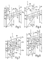
- Fig. 1
- einen aus dem Stand der Technik bekannten Grundrahmen in der Grundebene;
- Fig. 2
- die Bildung einer zweiten Arbeitsebene mittels eines U-förmigen Gerüstelementes;
- Fig. 3
- eine in der Arbeitsebene angeordnete Geländerstrebe und Kniestrebe;
- Fig. 4
- ein in der Arbeitsebene angeordnetes, T-förmiges Gerüstelement;
- Fig. 5
- eine am T-förmigen Gerüstelement angeordnete Gerüststrebe für eine nachfolgende Arbeitsebene;
- Fig. 6
- eine mit der Gerüststrebe verbundenes T-förmiges Gerüstelement im aufgesteckten Zustand;
- Fig. 7
- ein Fassadengerüst mit einer zweiten gebildeten Arbeitsebene;
- Fig. 8
- die Bildung einer dritten Arbeitsebene und Belagsicherung des Bodenelements mittels einem L-förmigen Gerüstelementes;
- Fig. 9
- ein Fassadengerüst mit zwei Arbeitsebenen und aufgestecktem T-förmigen Gerüstelement;
- Fig. 10
- ein fertig montiertes Fassadengerüst mit drei Arbeitsebenen und entsprechenden Geländerstreben;
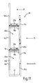
- Fig. 11
- eine Anordnung von U-, T- und L-förmigen Gerüstelementen zur Bildung eines Vertikalträgers;
- Fig. 1
- a known from the prior art base frame in the ground plane;
- Fig. 2
- the formation of a second working plane by means of a U-shaped framework element;
- Fig. 3
- a railing strut and knee brace arranged in the working plane;
- Fig. 4
- a T-shaped scaffolding element arranged in the working plane;
- Fig. 5
- a scaffold strut arranged on the T-shaped scaffolding element for a subsequent working plane;
- Fig. 6
- a connected to the framework strut T-shaped scaffolding element in the plugged state;
- Fig. 7
- a facade scaffolding with a second formed working plane;
- Fig. 8
- the formation of a third working level and securing the floor element by means of an L-shaped scaffold element;
- Fig. 9
- a facade scaffolding with two working levels and attached T-shaped scaffold element;
- Fig. 10
- a prefabricated facade scaffolding with three working levels and corresponding railing struts;
- Fig. 11
- an arrangement of U, T and L-shaped scaffolding elements to form a vertical support;
In
In
In
In
In
In
In
Die zweite Arbeitsebene 17 ist durch das vorherige Anordnen einer Geländerstrebe 9c, 9d aus der ersten Arbeitsebene 15 heraus abgesichert.The second working
In
In
In
In
Der Erfindungsgegenstand der vorliegenden Erfindung ergibt sich nicht nur aus dem Gegenstand der einzelnen Patentansprüche, sondern auch aus der Kombination der einzelnen Patentansprüche untereinander. Alle in den Unterlagen, einschließlich der Zusammenfassung, offenbarten Angaben und Merkmale, insbesondere die in der Zeichnung dargestellte räumliche Ausbildung, werden als erfindungswesentlich beansprucht, soweit Sie einzeln oder in Kombination gegenüber dem Stand der Technik neu sind.The subject of the present invention results not only from the subject matter of the individual claims, but also from the combination of the individual claims with each other. All information and features disclosed in the documents, including the abstract, in particular the spatial design shown in the drawing, are claimed as essential to the invention, as far as they are new individually or in combination with respect to the prior art.
- 11
- Fassadengerüstfacade scaffolding
- 22
- Grundrahmenbase frame
- 3a-3c3a-3c
- Vertikalrahmenvertical frame
- 44
- Verbindungsstrebeconnecting strut
- 5a-5c5a-5c
- Diagonalstrebediagonal strut
- 66
- Querriegel (Vertikalrahmen)Crossbar (vertical frame)
- 7a-7f7a-7f
- Bodenelementfloor element
- 8a-8c8a-8c
- U-förmiges GerüstelementU-shaped scaffolding element
- 9a-9f9a-9f
- Geländerstreberailing strut
- 1010
- Kniestrebeknee brace
- 11a-11f11a-11f
- T-förmiges GerüstelementT-shaped scaffolding element
- 1212
- Fußstützenfootrests
- 13a-13d13a-13d
- Auflage-Querriegel (T-förmiges Gerüstelement)Support crossbar (T-shaped framework element)
- 14a-14f14a-14f
- L-förmiges GerüstelementL-shaped scaffolding element
- 1515
- erste Arbeitsebenefirst working level
- 1616
- Grundebeneground plane
- 1717
- zweite Arbeitsebenesecond working level
- 1818
- nicht belegtnot used
- 1919
- dritte Arbeitsebenethird working level
- 2020
- Vertikalträgervertical support
- 2121
- Querriegel (U-förmiges Gerüstelement)Cross bar (U-shaped scaffolding element)
- 22a-22d22a-22d
- Vertikalrahmen (aus Gerüstelementen gebildet)Vertical frame (made up of scaffolding elements)
- 23a-23f23a-23f
- Bodenbelag-Sicherungsquerriegel (L-förmiges Gerüstelement)Flooring safety crossbar (L-shaped framework element)
- 24a-24b24a-24b
- Vertikalstiel (U-förmiges Gerüstelement)Vertical handle (U-shaped frame element)
- 25a-25b25a-25b
- Vertikalstiel (T-förmiges Gerüstelement)Vertical handle (T-shaped frame element)
- 26a-26c26a-26c
- Vertikalstiel (L-förmiges Gerüstelement)Vertical handle (L-shaped frame element)
Claims (10)
Priority Applications (1)
| Application Number | Priority Date | Filing Date | Title |
|---|---|---|---|
| PL12008094T PL2602402T3 (en) | 2011-12-06 | 2012-12-04 | Dismountable facade scaffold |
Applications Claiming Priority (1)
| Application Number | Priority Date | Filing Date | Title |
|---|---|---|---|
| DE201110120154 DE102011120154A1 (en) | 2011-12-06 | 2011-12-06 | Dismountable facade scaffolding |
Publications (3)
| Publication Number | Publication Date |
|---|---|
| EP2602402A2 true EP2602402A2 (en) | 2013-06-12 |
| EP2602402A3 EP2602402A3 (en) | 2014-07-30 |
| EP2602402B1 EP2602402B1 (en) | 2018-04-18 |
Family
ID=47504561
Family Applications (1)
| Application Number | Title | Priority Date | Filing Date |
|---|---|---|---|
| EP12008094.0A Active EP2602402B1 (en) | 2011-12-06 | 2012-12-04 | Dismountable facade scaffold |
Country Status (3)
| Country | Link |
|---|---|
| EP (1) | EP2602402B1 (en) |
| DE (1) | DE102011120154A1 (en) |
| PL (1) | PL2602402T3 (en) |
Family Cites Families (5)
| Publication number | Priority date | Publication date | Assignee | Title |
|---|---|---|---|---|
| CH439679A (en) * | 1966-08-27 | 1967-07-15 | Huwyler Rudolf | Scaffolding |
| JP4182012B2 (en) * | 2004-02-23 | 2008-11-19 | 株式会社ミルックス | How to build frame scaffolds and frame scaffolds |
| JP3872481B2 (en) * | 2004-03-01 | 2007-01-24 | ホリーエンジニアリング株式会社 | Building frame and manufacturing method of building frame |
| DE202006015586U1 (en) * | 2006-10-11 | 2008-02-21 | Wilhelm Layher Verwaltungs-Gmbh | Vertical frame element made of metal |
| DE102009049726A1 (en) * | 2009-10-17 | 2011-04-21 | Weiss, Johannes | Scaffolding for use in facade of building, has horizontal arm with sections pushable into each other and locked in different positions, and connector provided at ends for connecting scaffolding with vertical positioning frames or console |
-
2011
- 2011-12-06 DE DE201110120154 patent/DE102011120154A1/en not_active Withdrawn
-
2012
- 2012-12-04 EP EP12008094.0A patent/EP2602402B1/en active Active
- 2012-12-04 PL PL12008094T patent/PL2602402T3/en unknown
Non-Patent Citations (1)
| Title |
|---|
| None |
Also Published As
| Publication number | Publication date |
|---|---|
| PL2602402T3 (en) | 2018-09-28 |
| EP2602402B1 (en) | 2018-04-18 |
| DE102011120154A1 (en) | 2013-06-06 |
| EP2602402A3 (en) | 2014-07-30 |
Similar Documents
| Publication | Publication Date | Title |
|---|---|---|
| EP2279310B1 (en) | Track-guided self-climbing shuttering system with climbing rail extension pieces | |
| EP0918912B2 (en) | Dismountable facade scaffold | |
| DE2658583B2 (en) | Guard rails for scaffolding | |
| EP2557252B1 (en) | Work platform and method for securely setting up a support frame tower | |
| DE102007011777B4 (en) | Dismountable scaffolding and method for its construction and dismantling | |
| DE202022105308U1 (en) | Device for preventing people from falling | |
| DE820963C (en) | Scaffolding with stands made of tubes | |
| EP2602402B1 (en) | Dismountable facade scaffold | |
| EP2299028A2 (en) | Side guard rail for a scaffold | |
| DE2407103A1 (en) | Ladder scaffolding supporting working-platform - with triangle-grouped cantilevered supports with hooked traverses on base bar | |
| EP1370736B1 (en) | System of structural components for podiums/stages and/or stands and/or rostrums | |
| DE2910467A1 (en) | DEVICE FOR CHANGING THE HEIGHT OF THE STANDS OF A SCAFFOLDING TOWER | |
| EP3967831A1 (en) | Anti-fall device for reinforced soil | |
| DE3401906A1 (en) | Apparatus for the suspended fastening of a scaffold element | |
| EP1134331A2 (en) | Set of elements for a scaffold | |
| DE102019114913A1 (en) | Mounting adapters, safety railings, kit for a scaffolding and scaffolding and methods therefor | |
| DE3923815A1 (en) | FRAMEWORK | |
| EP3822431B1 (en) | Device and method for producing a leading side protection system for a scaffolding | |
| EP3440279B1 (en) | Starting crossbar for an ascension bay with ladder of a system scaffold, system scaffold having such starting crossbars, and method for mounting a system scaffold | |
| DE10121957A1 (en) | Safety net temporary support frame for use during erection and dismantling of building scaffolding | |
| DE202023105830U1 (en) | Device for attaching fall protection to scaffolding | |
| DE102022114668A1 (en) | Reinforcement device | |
| DE4114328A1 (en) | Bracket-frame suspension system from wall - has intermediate component with hook mounted at different heights | |
| DE2236165B2 (en) | framework | |
| DE1409400A1 (en) | Tribuene or similar spatial structure |
Legal Events
| Date | Code | Title | Description |
|---|---|---|---|
| PUAI | Public reference made under article 153(3) epc to a published international application that has entered the european phase |
Free format text: ORIGINAL CODE: 0009012 |
|
| AK | Designated contracting states |
Kind code of ref document: A2 Designated state(s): AL AT BE BG CH CY CZ DE DK EE ES FI FR GB GR HR HU IE IS IT LI LT LU LV MC MK MT NL NO PL PT RO RS SE SI SK SM TR |
|
| AX | Request for extension of the european patent |
Extension state: BA ME |
|
| PUAL | Search report despatched |
Free format text: ORIGINAL CODE: 0009013 |
|
| AK | Designated contracting states |
Kind code of ref document: A3 Designated state(s): AL AT BE BG CH CY CZ DE DK EE ES FI FR GB GR HR HU IE IS IT LI LT LU LV MC MK MT NL NO PL PT RO RS SE SI SK SM TR |
|
| AX | Request for extension of the european patent |
Extension state: BA ME |
|
| RIC1 | Information provided on ipc code assigned before grant |
Ipc: E04G 1/15 20060101AFI20140620BHEP Ipc: E04G 5/14 20060101ALI20140620BHEP Ipc: E04G 1/14 20060101ALI20140620BHEP |
|
| 17P | Request for examination filed |
Effective date: 20140822 |
|
| RBV | Designated contracting states (corrected) |
Designated state(s): AL AT BE BG CH CY CZ DE DK EE ES FI FR GB GR HR HU IE IS IT LI LT LU LV MC MK MT NL NO PL PT RO RS SE SI SK SM TR |
|
| 17Q | First examination report despatched |
Effective date: 20160519 |
|
| GRAP | Despatch of communication of intention to grant a patent |
Free format text: ORIGINAL CODE: EPIDOSNIGR1 |
|
| INTG | Intention to grant announced |
Effective date: 20170606 |
|
| GRAJ | Information related to disapproval of communication of intention to grant by the applicant or resumption of examination proceedings by the epo deleted |
Free format text: ORIGINAL CODE: EPIDOSDIGR1 |
|
| GRAP | Despatch of communication of intention to grant a patent |
Free format text: ORIGINAL CODE: EPIDOSNIGR1 |
|
| INTC | Intention to grant announced (deleted) | ||
| INTG | Intention to grant announced |
Effective date: 20171114 |
|
| GRAS | Grant fee paid |
Free format text: ORIGINAL CODE: EPIDOSNIGR3 |
|
| GRAA | (expected) grant |
Free format text: ORIGINAL CODE: 0009210 |
|
| AK | Designated contracting states |
Kind code of ref document: B1 Designated state(s): AL AT BE BG CH CY CZ DE DK EE ES FI FR GB GR HR HU IE IS IT LI LT LU LV MC MK MT NL NO PL PT RO RS SE SI SK SM TR |
|
| REG | Reference to a national code |
Ref country code: GB Ref legal event code: FG4D Free format text: NOT ENGLISH |
|
| REG | Reference to a national code |
Ref country code: CH Ref legal event code: EP |
|
| REG | Reference to a national code |
Ref country code: DE Ref legal event code: R096 Ref document number: 502012012535 Country of ref document: DE |
|
| REG | Reference to a national code |
Ref country code: AT Ref legal event code: REF Ref document number: 990650 Country of ref document: AT Kind code of ref document: T Effective date: 20180515 |
|
| REG | Reference to a national code |
Ref country code: IE Ref legal event code: FG4D Free format text: LANGUAGE OF EP DOCUMENT: GERMAN |
|
| REG | Reference to a national code |
Ref country code: CH Ref legal event code: NV Representative=s name: KELLER AND PARTNER PATENTANWAELTE AG, CH |
|
| REG | Reference to a national code |
Ref country code: SE Ref legal event code: TRGR |
|
| REG | Reference to a national code |
Ref country code: NL Ref legal event code: MP Effective date: 20180418 |
|
| REG | Reference to a national code |
Ref country code: LT Ref legal event code: MG4D |
|
| PG25 | Lapsed in a contracting state [announced via postgrant information from national office to epo] |
Ref country code: NL Free format text: LAPSE BECAUSE OF FAILURE TO SUBMIT A TRANSLATION OF THE DESCRIPTION OR TO PAY THE FEE WITHIN THE PRESCRIBED TIME-LIMIT Effective date: 20180418 |
|
| PG25 | Lapsed in a contracting state [announced via postgrant information from national office to epo] |
Ref country code: FI Free format text: LAPSE BECAUSE OF FAILURE TO SUBMIT A TRANSLATION OF THE DESCRIPTION OR TO PAY THE FEE WITHIN THE PRESCRIBED TIME-LIMIT Effective date: 20180418 Ref country code: LT Free format text: LAPSE BECAUSE OF FAILURE TO SUBMIT A TRANSLATION OF THE DESCRIPTION OR TO PAY THE FEE WITHIN THE PRESCRIBED TIME-LIMIT Effective date: 20180418 Ref country code: BG Free format text: LAPSE BECAUSE OF FAILURE TO SUBMIT A TRANSLATION OF THE DESCRIPTION OR TO PAY THE FEE WITHIN THE PRESCRIBED TIME-LIMIT Effective date: 20180718 Ref country code: ES Free format text: LAPSE BECAUSE OF FAILURE TO SUBMIT A TRANSLATION OF THE DESCRIPTION OR TO PAY THE FEE WITHIN THE PRESCRIBED TIME-LIMIT Effective date: 20180418 Ref country code: NO Free format text: LAPSE BECAUSE OF FAILURE TO SUBMIT A TRANSLATION OF THE DESCRIPTION OR TO PAY THE FEE WITHIN THE PRESCRIBED TIME-LIMIT Effective date: 20180718 Ref country code: AL Free format text: LAPSE BECAUSE OF FAILURE TO SUBMIT A TRANSLATION OF THE DESCRIPTION OR TO PAY THE FEE WITHIN THE PRESCRIBED TIME-LIMIT Effective date: 20180418 |
|
| PG25 | Lapsed in a contracting state [announced via postgrant information from national office to epo] |
Ref country code: HR Free format text: LAPSE BECAUSE OF FAILURE TO SUBMIT A TRANSLATION OF THE DESCRIPTION OR TO PAY THE FEE WITHIN THE PRESCRIBED TIME-LIMIT Effective date: 20180418 Ref country code: RS Free format text: LAPSE BECAUSE OF FAILURE TO SUBMIT A TRANSLATION OF THE DESCRIPTION OR TO PAY THE FEE WITHIN THE PRESCRIBED TIME-LIMIT Effective date: 20180418 Ref country code: LV Free format text: LAPSE BECAUSE OF FAILURE TO SUBMIT A TRANSLATION OF THE DESCRIPTION OR TO PAY THE FEE WITHIN THE PRESCRIBED TIME-LIMIT Effective date: 20180418 Ref country code: GR Free format text: LAPSE BECAUSE OF FAILURE TO SUBMIT A TRANSLATION OF THE DESCRIPTION OR TO PAY THE FEE WITHIN THE PRESCRIBED TIME-LIMIT Effective date: 20180719 |
|
| PG25 | Lapsed in a contracting state [announced via postgrant information from national office to epo] |
Ref country code: PT Free format text: LAPSE BECAUSE OF FAILURE TO SUBMIT A TRANSLATION OF THE DESCRIPTION OR TO PAY THE FEE WITHIN THE PRESCRIBED TIME-LIMIT Effective date: 20180820 |
|
| REG | Reference to a national code |
Ref country code: DE Ref legal event code: R097 Ref document number: 502012012535 Country of ref document: DE |
|
| PG25 | Lapsed in a contracting state [announced via postgrant information from national office to epo] |
Ref country code: DK Free format text: LAPSE BECAUSE OF FAILURE TO SUBMIT A TRANSLATION OF THE DESCRIPTION OR TO PAY THE FEE WITHIN THE PRESCRIBED TIME-LIMIT Effective date: 20180418 Ref country code: RO Free format text: LAPSE BECAUSE OF FAILURE TO SUBMIT A TRANSLATION OF THE DESCRIPTION OR TO PAY THE FEE WITHIN THE PRESCRIBED TIME-LIMIT Effective date: 20180418 Ref country code: SK Free format text: LAPSE BECAUSE OF FAILURE TO SUBMIT A TRANSLATION OF THE DESCRIPTION OR TO PAY THE FEE WITHIN THE PRESCRIBED TIME-LIMIT Effective date: 20180418 Ref country code: CZ Free format text: LAPSE BECAUSE OF FAILURE TO SUBMIT A TRANSLATION OF THE DESCRIPTION OR TO PAY THE FEE WITHIN THE PRESCRIBED TIME-LIMIT Effective date: 20180418 Ref country code: EE Free format text: LAPSE BECAUSE OF FAILURE TO SUBMIT A TRANSLATION OF THE DESCRIPTION OR TO PAY THE FEE WITHIN THE PRESCRIBED TIME-LIMIT Effective date: 20180418 |
|
| PLBE | No opposition filed within time limit |
Free format text: ORIGINAL CODE: 0009261 |
|
| STAA | Information on the status of an ep patent application or granted ep patent |
Free format text: STATUS: NO OPPOSITION FILED WITHIN TIME LIMIT |
|
| PG25 | Lapsed in a contracting state [announced via postgrant information from national office to epo] |
Ref country code: IT Free format text: LAPSE BECAUSE OF FAILURE TO SUBMIT A TRANSLATION OF THE DESCRIPTION OR TO PAY THE FEE WITHIN THE PRESCRIBED TIME-LIMIT Effective date: 20180418 Ref country code: SM Free format text: LAPSE BECAUSE OF FAILURE TO SUBMIT A TRANSLATION OF THE DESCRIPTION OR TO PAY THE FEE WITHIN THE PRESCRIBED TIME-LIMIT Effective date: 20180418 |
|
| 26N | No opposition filed |
Effective date: 20190121 |
|
| PG25 | Lapsed in a contracting state [announced via postgrant information from national office to epo] |
Ref country code: SI Free format text: LAPSE BECAUSE OF FAILURE TO SUBMIT A TRANSLATION OF THE DESCRIPTION OR TO PAY THE FEE WITHIN THE PRESCRIBED TIME-LIMIT Effective date: 20180418 |
|
| GBPC | Gb: european patent ceased through non-payment of renewal fee |
Effective date: 20181204 |
|
| PG25 | Lapsed in a contracting state [announced via postgrant information from national office to epo] |
Ref country code: LU Free format text: LAPSE BECAUSE OF NON-PAYMENT OF DUE FEES Effective date: 20181204 Ref country code: MC Free format text: LAPSE BECAUSE OF FAILURE TO SUBMIT A TRANSLATION OF THE DESCRIPTION OR TO PAY THE FEE WITHIN THE PRESCRIBED TIME-LIMIT Effective date: 20180418 |
|
| REG | Reference to a national code |
Ref country code: IE Ref legal event code: MM4A |
|
| REG | Reference to a national code |
Ref country code: BE Ref legal event code: MM Effective date: 20181231 |
|
| PG25 | Lapsed in a contracting state [announced via postgrant information from national office to epo] |
Ref country code: IE Free format text: LAPSE BECAUSE OF NON-PAYMENT OF DUE FEES Effective date: 20181204 |
|
| PG25 | Lapsed in a contracting state [announced via postgrant information from national office to epo] |
Ref country code: BE Free format text: LAPSE BECAUSE OF NON-PAYMENT OF DUE FEES Effective date: 20181231 |
|
| PG25 | Lapsed in a contracting state [announced via postgrant information from national office to epo] |
Ref country code: GB Free format text: LAPSE BECAUSE OF NON-PAYMENT OF DUE FEES Effective date: 20181204 |
|
| PG25 | Lapsed in a contracting state [announced via postgrant information from national office to epo] |
Ref country code: MT Free format text: LAPSE BECAUSE OF FAILURE TO SUBMIT A TRANSLATION OF THE DESCRIPTION OR TO PAY THE FEE WITHIN THE PRESCRIBED TIME-LIMIT Effective date: 20180418 |
|
| PG25 | Lapsed in a contracting state [announced via postgrant information from national office to epo] |
Ref country code: TR Free format text: LAPSE BECAUSE OF FAILURE TO SUBMIT A TRANSLATION OF THE DESCRIPTION OR TO PAY THE FEE WITHIN THE PRESCRIBED TIME-LIMIT Effective date: 20180418 |
|
| PG25 | Lapsed in a contracting state [announced via postgrant information from national office to epo] |
Ref country code: HU Free format text: LAPSE BECAUSE OF FAILURE TO SUBMIT A TRANSLATION OF THE DESCRIPTION OR TO PAY THE FEE WITHIN THE PRESCRIBED TIME-LIMIT; INVALID AB INITIO Effective date: 20121204 Ref country code: MK Free format text: LAPSE BECAUSE OF NON-PAYMENT OF DUE FEES Effective date: 20180418 Ref country code: CY Free format text: LAPSE BECAUSE OF FAILURE TO SUBMIT A TRANSLATION OF THE DESCRIPTION OR TO PAY THE FEE WITHIN THE PRESCRIBED TIME-LIMIT Effective date: 20180418 |
|
| PG25 | Lapsed in a contracting state [announced via postgrant information from national office to epo] |
Ref country code: IS Free format text: LAPSE BECAUSE OF FAILURE TO SUBMIT A TRANSLATION OF THE DESCRIPTION OR TO PAY THE FEE WITHIN THE PRESCRIBED TIME-LIMIT Effective date: 20180818 |
|
| REG | Reference to a national code |
Ref country code: CH Ref legal event code: PFA Owner name: ALTRAD PLETTAC ASSCO GMBH, DE Free format text: FORMER OWNER: ALTRAD PLETTAC ASSCO GMBH, DE |
|
| PGFP | Annual fee paid to national office [announced via postgrant information from national office to epo] |
Ref country code: PL Payment date: 20221118 Year of fee payment: 11 |
|
| PGFP | Annual fee paid to national office [announced via postgrant information from national office to epo] |
Ref country code: CH Payment date: 20230103 Year of fee payment: 11 |
|
| PGFP | Annual fee paid to national office [announced via postgrant information from national office to epo] |
Ref country code: SE Payment date: 20231219 Year of fee payment: 12 Ref country code: FR Payment date: 20231219 Year of fee payment: 12 Ref country code: DE Payment date: 20231214 Year of fee payment: 12 Ref country code: AT Payment date: 20231214 Year of fee payment: 12 |
|
| PGFP | Annual fee paid to national office [announced via postgrant information from national office to epo] |
Ref country code: PL Payment date: 20231122 Year of fee payment: 12 |