EP2602351B1 - Ferritic stainless steel - Google Patents
Ferritic stainless steel Download PDFInfo
- Publication number
- EP2602351B1 EP2602351B1 EP11814699.2A EP11814699A EP2602351B1 EP 2602351 B1 EP2602351 B1 EP 2602351B1 EP 11814699 A EP11814699 A EP 11814699A EP 2602351 B1 EP2602351 B1 EP 2602351B1
- Authority
- EP
- European Patent Office
- Prior art keywords
- black spots
- stainless steel
- amount
- ferritic stainless
- steel
- Prior art date
- Legal status (The legal status is an assumption and is not a legal conclusion. Google has not performed a legal analysis and makes no representation as to the accuracy of the status listed.)
- Active
Links
- 229910001220 stainless steel Inorganic materials 0.000 title claims description 34
- 229910000831 Steel Inorganic materials 0.000 claims description 36
- 239000010959 steel Substances 0.000 claims description 36
- 238000003466 welding Methods 0.000 claims description 36
- 229910052719 titanium Inorganic materials 0.000 claims description 26
- 229910052782 aluminium Inorganic materials 0.000 claims description 23
- 229910052791 calcium Inorganic materials 0.000 claims description 18
- 229910052710 silicon Inorganic materials 0.000 claims description 17
- 239000012535 impurity Substances 0.000 claims description 5
- 229910052742 iron Inorganic materials 0.000 claims description 4
- 229910052726 zirconium Inorganic materials 0.000 claims description 2
- 238000012360 testing method Methods 0.000 description 69
- 238000005260 corrosion Methods 0.000 description 52
- 230000007797 corrosion Effects 0.000 description 52
- 239000010936 titanium Substances 0.000 description 38
- 239000011575 calcium Substances 0.000 description 31
- 206010027146 Melanoderma Diseases 0.000 description 18
- PXHVJJICTQNCMI-UHFFFAOYSA-N Nickel Chemical compound [Ni] PXHVJJICTQNCMI-UHFFFAOYSA-N 0.000 description 15
- 230000015572 biosynthetic process Effects 0.000 description 15
- 239000010955 niobium Substances 0.000 description 15
- 239000011651 chromium Substances 0.000 description 14
- 230000000052 comparative effect Effects 0.000 description 14
- 230000000694 effects Effects 0.000 description 13
- JEIPFZHSYJVQDO-UHFFFAOYSA-N iron(III) oxide Inorganic materials O=[Fe]O[Fe]=O JEIPFZHSYJVQDO-UHFFFAOYSA-N 0.000 description 12
- 239000000463 material Substances 0.000 description 11
- 229910052757 nitrogen Inorganic materials 0.000 description 11
- 239000011572 manganese Substances 0.000 description 10
- 238000000034 method Methods 0.000 description 10
- 239000000203 mixture Substances 0.000 description 10
- 239000011324 bead Substances 0.000 description 8
- 229910052799 carbon Inorganic materials 0.000 description 8
- 239000010949 copper Substances 0.000 description 8
- 238000000682 scanning probe acoustic microscopy Methods 0.000 description 8
- XEEYBQQBJWHFJM-UHFFFAOYSA-N Iron Chemical group [Fe] XEEYBQQBJWHFJM-UHFFFAOYSA-N 0.000 description 7
- 239000007921 spray Substances 0.000 description 7
- 239000000126 substance Substances 0.000 description 7
- FAPWRFPIFSIZLT-UHFFFAOYSA-M Sodium chloride Chemical compound [Na+].[Cl-] FAPWRFPIFSIZLT-UHFFFAOYSA-M 0.000 description 6
- 229910052804 chromium Inorganic materials 0.000 description 6
- 230000002708 enhancing effect Effects 0.000 description 5
- 230000001965 increasing effect Effects 0.000 description 5
- 229910052751 metal Inorganic materials 0.000 description 5
- 239000002184 metal Substances 0.000 description 5
- 229910052750 molybdenum Inorganic materials 0.000 description 5
- 229910052759 nickel Inorganic materials 0.000 description 5
- 229910052758 niobium Inorganic materials 0.000 description 5
- XLYOFNOQVPJJNP-UHFFFAOYSA-N water Substances O XLYOFNOQVPJJNP-UHFFFAOYSA-N 0.000 description 5
- QVGXLLKOCUKJST-UHFFFAOYSA-N atomic oxygen Chemical compound [O] QVGXLLKOCUKJST-UHFFFAOYSA-N 0.000 description 4
- 230000006866 deterioration Effects 0.000 description 4
- 238000009826 distribution Methods 0.000 description 4
- 238000004299 exfoliation Methods 0.000 description 4
- 239000001301 oxygen Substances 0.000 description 4
- 229910052760 oxygen Inorganic materials 0.000 description 4
- 229910000859 α-Fe Inorganic materials 0.000 description 4
- 238000004458 analytical method Methods 0.000 description 3
- 229910000963 austenitic stainless steel Inorganic materials 0.000 description 3
- 239000011261 inert gas Substances 0.000 description 3
- 238000005259 measurement Methods 0.000 description 3
- 239000011780 sodium chloride Substances 0.000 description 3
- 239000010935 stainless steel Substances 0.000 description 3
- 229910052717 sulfur Inorganic materials 0.000 description 3
- XKRFYHLGVUSROY-UHFFFAOYSA-N Argon Chemical compound [Ar] XKRFYHLGVUSROY-UHFFFAOYSA-N 0.000 description 2
- IJGRMHOSHXDMSA-UHFFFAOYSA-N Atomic nitrogen Chemical compound N#N IJGRMHOSHXDMSA-UHFFFAOYSA-N 0.000 description 2
- 206010070834 Sensitisation Diseases 0.000 description 2
- 238000005097 cold rolling Methods 0.000 description 2
- 229910052802 copper Inorganic materials 0.000 description 2
- 238000004090 dissolution Methods 0.000 description 2
- 229910052748 manganese Inorganic materials 0.000 description 2
- 238000004519 manufacturing process Methods 0.000 description 2
- 229910052698 phosphorus Inorganic materials 0.000 description 2
- 238000007670 refining Methods 0.000 description 2
- 230000001105 regulatory effect Effects 0.000 description 2
- 230000008313 sensitization Effects 0.000 description 2
- ZOXJGFHDIHLPTG-UHFFFAOYSA-N Boron Chemical compound [B] ZOXJGFHDIHLPTG-UHFFFAOYSA-N 0.000 description 1
- OYPRJOBELJOOCE-UHFFFAOYSA-N Calcium Chemical compound [Ca] OYPRJOBELJOOCE-UHFFFAOYSA-N 0.000 description 1
- OKTJSMMVPCPJKN-UHFFFAOYSA-N Carbon Chemical compound [C] OKTJSMMVPCPJKN-UHFFFAOYSA-N 0.000 description 1
- VYZAMTAEIAYCRO-UHFFFAOYSA-N Chromium Chemical compound [Cr] VYZAMTAEIAYCRO-UHFFFAOYSA-N 0.000 description 1
- RYGMFSIKBFXOCR-UHFFFAOYSA-N Copper Chemical compound [Cu] RYGMFSIKBFXOCR-UHFFFAOYSA-N 0.000 description 1
- 229910001208 Crucible steel Inorganic materials 0.000 description 1
- UFHFLCQGNIYNRP-UHFFFAOYSA-N Hydrogen Chemical compound [H][H] UFHFLCQGNIYNRP-UHFFFAOYSA-N 0.000 description 1
- PWHULOQIROXLJO-UHFFFAOYSA-N Manganese Chemical compound [Mn] PWHULOQIROXLJO-UHFFFAOYSA-N 0.000 description 1
- ZOKXTWBITQBERF-UHFFFAOYSA-N Molybdenum Chemical compound [Mo] ZOKXTWBITQBERF-UHFFFAOYSA-N 0.000 description 1
- XUIMIQQOPSSXEZ-UHFFFAOYSA-N Silicon Chemical compound [Si] XUIMIQQOPSSXEZ-UHFFFAOYSA-N 0.000 description 1
- NINIDFKCEFEMDL-UHFFFAOYSA-N Sulfur Chemical compound [S] NINIDFKCEFEMDL-UHFFFAOYSA-N 0.000 description 1
- RTAQQCXQSZGOHL-UHFFFAOYSA-N Titanium Chemical compound [Ti] RTAQQCXQSZGOHL-UHFFFAOYSA-N 0.000 description 1
- 230000001133 acceleration Effects 0.000 description 1
- 239000002253 acid Substances 0.000 description 1
- XAGFODPZIPBFFR-UHFFFAOYSA-N aluminium Chemical compound [Al] XAGFODPZIPBFFR-UHFFFAOYSA-N 0.000 description 1
- 229910052786 argon Inorganic materials 0.000 description 1
- 230000006399 behavior Effects 0.000 description 1
- 229910052796 boron Inorganic materials 0.000 description 1
- 239000004566 building material Substances 0.000 description 1
- 238000004140 cleaning Methods 0.000 description 1
- 239000012611 container material Substances 0.000 description 1
- 230000001276 controlling effect Effects 0.000 description 1
- 238000005336 cracking Methods 0.000 description 1
- 230000001419 dependent effect Effects 0.000 description 1
- 230000002542 deteriorative effect Effects 0.000 description 1
- 238000011156 evaluation Methods 0.000 description 1
- 238000002474 experimental method Methods 0.000 description 1
- 239000000945 filler Substances 0.000 description 1
- 239000007789 gas Substances 0.000 description 1
- 239000011521 glass Substances 0.000 description 1
- 238000005098 hot rolling Methods 0.000 description 1
- BHEPBYXIRTUNPN-UHFFFAOYSA-N hydridophosphorus(.) (triplet) Chemical compound [PH] BHEPBYXIRTUNPN-UHFFFAOYSA-N 0.000 description 1
- 239000001257 hydrogen Substances 0.000 description 1
- 229910052739 hydrogen Inorganic materials 0.000 description 1
- -1 if present Substances 0.000 description 1
- 239000000155 melt Substances 0.000 description 1
- 230000008018 melting Effects 0.000 description 1
- 238000002844 melting Methods 0.000 description 1
- 239000011733 molybdenum Substances 0.000 description 1
- GUCVJGMIXFAOAE-UHFFFAOYSA-N niobium atom Chemical compound [Nb] GUCVJGMIXFAOAE-UHFFFAOYSA-N 0.000 description 1
- 230000003647 oxidation Effects 0.000 description 1
- 238000007254 oxidation reaction Methods 0.000 description 1
- 230000035515 penetration Effects 0.000 description 1
- 238000005554 pickling Methods 0.000 description 1
- 238000005498 polishing Methods 0.000 description 1
- 238000012545 processing Methods 0.000 description 1
- 239000002994 raw material Substances 0.000 description 1
- 238000001953 recrystallisation Methods 0.000 description 1
- 238000011160 research Methods 0.000 description 1
- 238000006748 scratching Methods 0.000 description 1
- 230000002393 scratching effect Effects 0.000 description 1
- VSZWPYCFIRKVQL-UHFFFAOYSA-N selanylidenegallium;selenium Chemical compound [Se].[Se]=[Ga].[Se]=[Ga] VSZWPYCFIRKVQL-UHFFFAOYSA-N 0.000 description 1
- 239000010703 silicon Substances 0.000 description 1
- 239000002893 slag Substances 0.000 description 1
- 238000007711 solidification Methods 0.000 description 1
- 230000008023 solidification Effects 0.000 description 1
- 238000001228 spectrum Methods 0.000 description 1
- 238000004544 sputter deposition Methods 0.000 description 1
- 230000000087 stabilizing effect Effects 0.000 description 1
- 238000005728 strengthening Methods 0.000 description 1
- 239000011593 sulfur Substances 0.000 description 1
- WFKWXMTUELFFGS-UHFFFAOYSA-N tungsten Chemical compound [W] WFKWXMTUELFFGS-UHFFFAOYSA-N 0.000 description 1
- 229910052721 tungsten Inorganic materials 0.000 description 1
- 239000010937 tungsten Substances 0.000 description 1
- 229910052720 vanadium Inorganic materials 0.000 description 1
- LEONUFNNVUYDNQ-UHFFFAOYSA-N vanadium atom Chemical compound [V] LEONUFNNVUYDNQ-UHFFFAOYSA-N 0.000 description 1
Images

Classifications
-
- C—CHEMISTRY; METALLURGY
- C22—METALLURGY; FERROUS OR NON-FERROUS ALLOYS; TREATMENT OF ALLOYS OR NON-FERROUS METALS
- C22C—ALLOYS
- C22C38/00—Ferrous alloys, e.g. steel alloys
- C22C38/18—Ferrous alloys, e.g. steel alloys containing chromium
- C22C38/40—Ferrous alloys, e.g. steel alloys containing chromium with nickel
- C22C38/54—Ferrous alloys, e.g. steel alloys containing chromium with nickel with boron
-
- C—CHEMISTRY; METALLURGY
- C21—METALLURGY OF IRON
- C21D—MODIFYING THE PHYSICAL STRUCTURE OF FERROUS METALS; GENERAL DEVICES FOR HEAT TREATMENT OF FERROUS OR NON-FERROUS METALS OR ALLOYS; MAKING METAL MALLEABLE, e.g. BY DECARBURISATION OR TEMPERING
- C21D6/00—Heat treatment of ferrous alloys
- C21D6/002—Heat treatment of ferrous alloys containing Cr
-
- C—CHEMISTRY; METALLURGY
- C21—METALLURGY OF IRON
- C21D—MODIFYING THE PHYSICAL STRUCTURE OF FERROUS METALS; GENERAL DEVICES FOR HEAT TREATMENT OF FERROUS OR NON-FERROUS METALS OR ALLOYS; MAKING METAL MALLEABLE, e.g. BY DECARBURISATION OR TEMPERING
- C21D8/00—Modifying the physical properties by deformation combined with, or followed by, heat treatment
- C21D8/02—Modifying the physical properties by deformation combined with, or followed by, heat treatment during manufacturing of plates or strips
- C21D8/0221—Modifying the physical properties by deformation combined with, or followed by, heat treatment during manufacturing of plates or strips characterised by the working steps
- C21D8/0226—Hot rolling
-
- C—CHEMISTRY; METALLURGY
- C21—METALLURGY OF IRON
- C21D—MODIFYING THE PHYSICAL STRUCTURE OF FERROUS METALS; GENERAL DEVICES FOR HEAT TREATMENT OF FERROUS OR NON-FERROUS METALS OR ALLOYS; MAKING METAL MALLEABLE, e.g. BY DECARBURISATION OR TEMPERING
- C21D8/00—Modifying the physical properties by deformation combined with, or followed by, heat treatment
- C21D8/02—Modifying the physical properties by deformation combined with, or followed by, heat treatment during manufacturing of plates or strips
- C21D8/0221—Modifying the physical properties by deformation combined with, or followed by, heat treatment during manufacturing of plates or strips characterised by the working steps
- C21D8/0236—Cold rolling
-
- C—CHEMISTRY; METALLURGY
- C21—METALLURGY OF IRON
- C21D—MODIFYING THE PHYSICAL STRUCTURE OF FERROUS METALS; GENERAL DEVICES FOR HEAT TREATMENT OF FERROUS OR NON-FERROUS METALS OR ALLOYS; MAKING METAL MALLEABLE, e.g. BY DECARBURISATION OR TEMPERING
- C21D8/00—Modifying the physical properties by deformation combined with, or followed by, heat treatment
- C21D8/02—Modifying the physical properties by deformation combined with, or followed by, heat treatment during manufacturing of plates or strips
- C21D8/0247—Modifying the physical properties by deformation combined with, or followed by, heat treatment during manufacturing of plates or strips characterised by the heat treatment
- C21D8/0263—Modifying the physical properties by deformation combined with, or followed by, heat treatment during manufacturing of plates or strips characterised by the heat treatment following hot rolling
-
- C—CHEMISTRY; METALLURGY
- C22—METALLURGY; FERROUS OR NON-FERROUS ALLOYS; TREATMENT OF ALLOYS OR NON-FERROUS METALS
- C22C—ALLOYS
- C22C38/00—Ferrous alloys, e.g. steel alloys
- C22C38/001—Ferrous alloys, e.g. steel alloys containing N
-
- C—CHEMISTRY; METALLURGY
- C22—METALLURGY; FERROUS OR NON-FERROUS ALLOYS; TREATMENT OF ALLOYS OR NON-FERROUS METALS
- C22C—ALLOYS
- C22C38/00—Ferrous alloys, e.g. steel alloys
- C22C38/002—Ferrous alloys, e.g. steel alloys containing In, Mg, or other elements not provided for in one single group C22C38/001 - C22C38/60
-
- C—CHEMISTRY; METALLURGY
- C22—METALLURGY; FERROUS OR NON-FERROUS ALLOYS; TREATMENT OF ALLOYS OR NON-FERROUS METALS
- C22C—ALLOYS
- C22C38/00—Ferrous alloys, e.g. steel alloys
- C22C38/004—Very low carbon steels, i.e. having a carbon content of less than 0,01%
-
- C—CHEMISTRY; METALLURGY
- C22—METALLURGY; FERROUS OR NON-FERROUS ALLOYS; TREATMENT OF ALLOYS OR NON-FERROUS METALS
- C22C—ALLOYS
- C22C38/00—Ferrous alloys, e.g. steel alloys
- C22C38/02—Ferrous alloys, e.g. steel alloys containing silicon
-
- C—CHEMISTRY; METALLURGY
- C22—METALLURGY; FERROUS OR NON-FERROUS ALLOYS; TREATMENT OF ALLOYS OR NON-FERROUS METALS
- C22C—ALLOYS
- C22C38/00—Ferrous alloys, e.g. steel alloys
- C22C38/04—Ferrous alloys, e.g. steel alloys containing manganese
-
- C—CHEMISTRY; METALLURGY
- C22—METALLURGY; FERROUS OR NON-FERROUS ALLOYS; TREATMENT OF ALLOYS OR NON-FERROUS METALS
- C22C—ALLOYS
- C22C38/00—Ferrous alloys, e.g. steel alloys
- C22C38/06—Ferrous alloys, e.g. steel alloys containing aluminium
-
- C—CHEMISTRY; METALLURGY
- C22—METALLURGY; FERROUS OR NON-FERROUS ALLOYS; TREATMENT OF ALLOYS OR NON-FERROUS METALS
- C22C—ALLOYS
- C22C38/00—Ferrous alloys, e.g. steel alloys
- C22C38/18—Ferrous alloys, e.g. steel alloys containing chromium
- C22C38/20—Ferrous alloys, e.g. steel alloys containing chromium with copper
-
- C—CHEMISTRY; METALLURGY
- C22—METALLURGY; FERROUS OR NON-FERROUS ALLOYS; TREATMENT OF ALLOYS OR NON-FERROUS METALS
- C22C—ALLOYS
- C22C38/00—Ferrous alloys, e.g. steel alloys
- C22C38/18—Ferrous alloys, e.g. steel alloys containing chromium
- C22C38/22—Ferrous alloys, e.g. steel alloys containing chromium with molybdenum or tungsten
-
- C—CHEMISTRY; METALLURGY
- C22—METALLURGY; FERROUS OR NON-FERROUS ALLOYS; TREATMENT OF ALLOYS OR NON-FERROUS METALS
- C22C—ALLOYS
- C22C38/00—Ferrous alloys, e.g. steel alloys
- C22C38/18—Ferrous alloys, e.g. steel alloys containing chromium
- C22C38/24—Ferrous alloys, e.g. steel alloys containing chromium with vanadium
-
- C—CHEMISTRY; METALLURGY
- C22—METALLURGY; FERROUS OR NON-FERROUS ALLOYS; TREATMENT OF ALLOYS OR NON-FERROUS METALS
- C22C—ALLOYS
- C22C38/00—Ferrous alloys, e.g. steel alloys
- C22C38/18—Ferrous alloys, e.g. steel alloys containing chromium
- C22C38/26—Ferrous alloys, e.g. steel alloys containing chromium with niobium or tantalum
-
- C—CHEMISTRY; METALLURGY
- C22—METALLURGY; FERROUS OR NON-FERROUS ALLOYS; TREATMENT OF ALLOYS OR NON-FERROUS METALS
- C22C—ALLOYS
- C22C38/00—Ferrous alloys, e.g. steel alloys
- C22C38/18—Ferrous alloys, e.g. steel alloys containing chromium
- C22C38/28—Ferrous alloys, e.g. steel alloys containing chromium with titanium or zirconium
-
- C—CHEMISTRY; METALLURGY
- C22—METALLURGY; FERROUS OR NON-FERROUS ALLOYS; TREATMENT OF ALLOYS OR NON-FERROUS METALS
- C22C—ALLOYS
- C22C38/00—Ferrous alloys, e.g. steel alloys
- C22C38/18—Ferrous alloys, e.g. steel alloys containing chromium
- C22C38/32—Ferrous alloys, e.g. steel alloys containing chromium with boron
-
- C—CHEMISTRY; METALLURGY
- C22—METALLURGY; FERROUS OR NON-FERROUS ALLOYS; TREATMENT OF ALLOYS OR NON-FERROUS METALS
- C22C—ALLOYS
- C22C38/00—Ferrous alloys, e.g. steel alloys
- C22C38/18—Ferrous alloys, e.g. steel alloys containing chromium
- C22C38/40—Ferrous alloys, e.g. steel alloys containing chromium with nickel
- C22C38/42—Ferrous alloys, e.g. steel alloys containing chromium with nickel with copper
-
- C—CHEMISTRY; METALLURGY
- C22—METALLURGY; FERROUS OR NON-FERROUS ALLOYS; TREATMENT OF ALLOYS OR NON-FERROUS METALS
- C22C—ALLOYS
- C22C38/00—Ferrous alloys, e.g. steel alloys
- C22C38/18—Ferrous alloys, e.g. steel alloys containing chromium
- C22C38/40—Ferrous alloys, e.g. steel alloys containing chromium with nickel
- C22C38/44—Ferrous alloys, e.g. steel alloys containing chromium with nickel with molybdenum or tungsten
-
- C—CHEMISTRY; METALLURGY
- C22—METALLURGY; FERROUS OR NON-FERROUS ALLOYS; TREATMENT OF ALLOYS OR NON-FERROUS METALS
- C22C—ALLOYS
- C22C38/00—Ferrous alloys, e.g. steel alloys
- C22C38/18—Ferrous alloys, e.g. steel alloys containing chromium
- C22C38/40—Ferrous alloys, e.g. steel alloys containing chromium with nickel
- C22C38/46—Ferrous alloys, e.g. steel alloys containing chromium with nickel with vanadium
-
- C—CHEMISTRY; METALLURGY
- C22—METALLURGY; FERROUS OR NON-FERROUS ALLOYS; TREATMENT OF ALLOYS OR NON-FERROUS METALS
- C22C—ALLOYS
- C22C38/00—Ferrous alloys, e.g. steel alloys
- C22C38/18—Ferrous alloys, e.g. steel alloys containing chromium
- C22C38/40—Ferrous alloys, e.g. steel alloys containing chromium with nickel
- C22C38/48—Ferrous alloys, e.g. steel alloys containing chromium with nickel with niobium or tantalum
-
- C—CHEMISTRY; METALLURGY
- C22—METALLURGY; FERROUS OR NON-FERROUS ALLOYS; TREATMENT OF ALLOYS OR NON-FERROUS METALS
- C22C—ALLOYS
- C22C38/00—Ferrous alloys, e.g. steel alloys
- C22C38/18—Ferrous alloys, e.g. steel alloys containing chromium
- C22C38/40—Ferrous alloys, e.g. steel alloys containing chromium with nickel
- C22C38/50—Ferrous alloys, e.g. steel alloys containing chromium with nickel with titanium or zirconium
-
- F—MECHANICAL ENGINEERING; LIGHTING; HEATING; WEAPONS; BLASTING
- F28—HEAT EXCHANGE IN GENERAL
- F28F—DETAILS OF HEAT-EXCHANGE AND HEAT-TRANSFER APPARATUS, OF GENERAL APPLICATION
- F28F21/00—Constructions of heat-exchange apparatus characterised by the selection of particular materials
- F28F21/08—Constructions of heat-exchange apparatus characterised by the selection of particular materials of metal
- F28F21/081—Heat exchange elements made from metals or metal alloys
- F28F21/082—Heat exchange elements made from metals or metal alloys from steel or ferrous alloys
- F28F21/083—Heat exchange elements made from metals or metal alloys from steel or ferrous alloys from stainless steel
Definitions
- the present invention relates to a ferritic stainless steel that generates only a small amount of black spots in the TIG weld zone.
- Ferritic stainless steel generally has properties such as a small expansion coefficient relative to the austenitic stainless steel and excellent resistance to stress corrosion cracking in addition to excellent corrosion resistance. Therefore, the ferritic stainless steel is widely used in tableware, kitchen equipment, building exterior materials such as roof materials, water or hot water container materials or the like. Further, there is increasing demand for replacement of austenitic stainless steel due to recent increasing price of nickel raw material, and the uses of ferritic stainless steel have expanded.
- Patent Reference 3 discloses a technique of improving crevice corrosion resistance of the weld zone by adding a certain amount or more of Si in addition to combined addition of Al and Ti.
- Patent Reference 4 discloses a technique to improve the corrosion resistance of a weld zone by satisfying 4Al + Ti ⁇ 0.32 (wherein each of Ti and Al denotes amount of each component in the steel), thereby reducing heat input during the welding and suppressing generation of scale in the weld zone, and improving corrosion resistance of the weld zone.
- Patent Reference 5 there is a technique to improve the weather resistance and crevice corrosion resistance of not the weld zone but the material itself by intentionally adding P and appropriate amounts of Ca and Al (for example, see Patent Reference 5).
- Ca and Al are added to control the shapes and distribution of non-metallic inclusions in the steel.
- the most important feature of Patent Reference 5 is the addition of P in excess of 0.04%, and Patent Reference 5 describes nothing about an effect during welding.
- JP 2006 263811 A discloses a ferritic stainless steel filler metal rod for TIG welding satisfying the conditions of Ti/Al ⁇ 5 and (Ti+Nb)/(C+N)>30.
- black spots In the conventional ferritic stainless steel, dark spots (so called black spots or slag spots) occasionally occurred on the surfaces of back beads after the welding even though shielding conditions in the weld zone were controlled appropriately.
- Elements such as Al, Ti, Si, Ca have a strong affinity to oxygen.
- Black spots are oxides of these elements that are solidified on the surface of the weld metal during the solidification process of the weld metal formed by Tungsten Inert Gas (TIG) welding.
- Tungsten Inert Gas (TIG) welding Tungsten Inert Gas
- the black spot itself is an oxide
- the black spots are generated in a large amount or generated in a continuously linked manner, the appearance of the weld material used without polishing the weld zone is worsened.
- exfoliation of the black spots portion occasionally occurs during working of the weld zone.
- problems such as deterioration of workability and/or occurrence of crevice corrosion in the interstitial area between the weld metal and the exfoliated black spots occasionally occur.
- exfoliation of the black spots and the resultant deterioration of corrosion resistance occasionally occur in the member having a structure in which stress is loaded on the weld zone.
- the corrosion resistance of the TIG weld zone it is important to not only improve the corrosion resistance of the weld bead portion itself and weld scale portion itself, but also to control the occurrence of black spots in the weld zone.
- the scale that is generated during the welding and accompanies the change of color can be mostly suppressed by the method of enhancing shielding conditions during welding.
- the black spots generated in the TIG weld zone could not be suppressed sufficiently in accordance with the prior arts even when the shielding conditions were enhanced.
- an object of the present invention is to provide a ferritic stainless steel that is resistant to the generation of black spots in the TIG weld zone and exhibits excellent corrosion resistance and workability in the weld zone.
- the inventors performed extensive research to suppress the amount of generation of black spots. As a result, the inventors found that the generation of black spots in the TIG weld zone could be suppressed by optimizing the amounts of Al, Ti, Si, and Ca, and reached the invention of the ferritic stainless steel in which black spots are generated only in a small amount.
- a ferritic stainless steel according to the present invention that generates only a small amount of black spot satisfies the below described formula 1.
- BI 3 ⁇ Al + Ti + 0.5 ⁇ Si + 200 ⁇ Ca ⁇ 0.8
- Al, Ti, Si, and Ca in the formula 1 each denotes an amount of each element in the steel in mass %.
- Al, Ti, Si, and Ca are elements that have a specifically strong affinity with oxygen and that generate black spots at the time of TIG welding. As the amount of Al, Ti, Si, and Ca contained in the steel increases, black spots are easily generated.
- the coefficients of the amounts of Al, Ti, Si, and Ca in the above-described formula 1 are determined based on the degree (strength) of the effect of enhancing the generation of black spots and the amounts in the steel. Specifically, as it is shown in the following experimental example, Al is an element that is included in the black spot at the highest concentration and has a specifically large effect of enhancing the generation of black spots. Therefore, coefficient of the Al content in the above-described formula 1 is determined to be 3.
- the coefficient of the Ca content is determined to be 200.
- the generation of black spots is prominent.
- the BI value is 0.8 or less
- the generation of black spots in the TIG weld zone is sufficiently reduced, and an excellent corrosion resistance is obtained.
- the BI value is 0.6 or less
- the BI value is 0.4 or less
- the generation of black spots is mostly suppressed, and it is possible to further improve the corrosion resistance of the TIG weld zone.
- the black spot portion Under conditions in which a large amount of black spots tend to occur, the black spot portion has a large thickness. It is considered that such a portion is easily exfoliated at the time of working, and that severe working such as bulging causes the exfoliation and provides a starting point for corrosion. On the contrary, the black spots have thin thickness under conditions in which black spots are generated in a small amount. Therefore, it is considered that even when black spots are generated, the black spots are not exfoliated easily. Therefore, it is considered that corrosion resistance of the weld zone can be suppressed by suppressing the generation of black spots.
- Al is important as an deoxidizing element and has an effect in grain-refinement of the microstructure of the steel by controlling the composition of non-metallic inclusion.
- Al is an element that has the largest contribution to the generation of black spots.
- excessive addition of Al causes coarsening of the non-metallic inclusions that may act as starting points of scratching in the product. Therefore, the upper limit of the amount of Al was determined to be 0.12%.
- the steel contains 0.01% or more of Al with the purpose of deoxidization. More preferably, the amount of Al is 0.03% to 0.10%.
- Ti is an very important element for fixing C and N and suppressing grain boundary corrosion in the weld zone, thereby improving workability.
- excessive addition of Ti results in not only generation of black spots but also occurrence of surface scratches during the production process. Therefore, the range of the amount of Ti was determined to be 0.05% to 0.35%. More preferable range is 0.07% to 0.20%.
- Si is an important element as an deoxidizing element and is effective in improvement of corrosion resistance and oxidation resistance.
- excessive addition of Si results in not only enhancement of generation of black spots but also deterioration of workability and productivity. Therefore, the upper limit of the amount of Si was determined to be 1.0%.
- the steel contains 0.01% or more of Si for the purpose of deoxidization.
- the amount of Si is 0.05% to 0.55%.
- Ca is very important as an deoxidizing element and is contained in the steel in small amount in the form of non-metallic inclusion.
- Ca since Ca is oxidized very easily, Ca behaves as strong cause of generation of black spots in the time of welding.
- the amount of Ca it is preferable to control the amount of Ca to be as small as possible, and the upper limit of the amount of Ca was determined to be 0.0015%. More preferably, the amount of Ca is 0.0012% or less.
- the amount of C must be suppressed since C deteriorates grain boundary corrosion resistance and workability. Therefore the upper limit of C was determined to be 0.020%. On the other hand, excessive reduction of C causes an increase in the refining cost. Therefore, the amount of C is preferably 0.002% to 0.015%.
- the amount of N is preferably 0.002% to 0.015%.
- the amount of Mn was controlled to be 1.0% or less.
- the steel contains 0.01% or more of Mn.
- the amount of Mn is 0.05% to 0.5%, and more preferably, 0.05% to 0.3%.
- Phosphorous (P) 0.001 to 0.035% by mass
- the amount of P must be suppressed to low value since P deteriorates weldability and workability and makes the grain boundary corrosion easily occur. Therefore, the amount of P was controlled to be 0.035% or less. A more preferable amount of P is 0.001% to 0.02%.
- the amount of S must be reduced since S generates water-soluble inclusions such as CaS and MnS that act as starting points of corrosion. Therefore, the amount of S is controlled to be 0.01% or less. On the other hand, excessive reduction of S results in deterioration of the cost. Therefore, the amount of S is preferably 0.0001% to 0.005%.
- Cr is the most important element for ensuring corrosion resistance of the stainless steel. In order to stabilize the ferrite microstructure, it is necessary for the steel to contain 16.0% or more of Cr. On the other hand Cr deteriorates the workability and productivity of the steel. Therefore, the upper limit of Cr content was determined to be 25.0%. Preferably, the amount of Cr is 16.5% to 23.0%, and more preferably, 18.0% to 22.5%.
- Nb has properties such that Nb may be added alone, or in combination with Ti. Where Nb and Ti are added in combination, it is preferable that the formula: (Ti+Nb)/(C+N) ⁇ 6 is satisfied, where Ti, Nb, C, and N in the formula each denote the amount in mass % of each element in the steel.
- Nb fixes C and N, suppress grain boundary corrosion of weld-zone, and improves workability.
- excessive addition of Nb deteriorates workability of the steel. Therefore, it is preferable to control the upper limit of the amount of Nb to be 0.6%.
- the steel In order to improve the above-described properties by the content of Nb, it is preferable for the steel to contain 0.05% or more of Nb.
- the amount of Nb is 0.15% to 0.55%.
- the stainless steel sheet contains optionally one or more of 0.30 to 3.0% of Mo, 0.05 to 2.0% of Cn, 0.05 to 2.0% of Ni, 0.03 to 0.2% of V, 0.03 to 0.2% of Zr and 0.0001 to 0.005% of B.
- Mo is an element that has an effect of repairing the passive film and is very effective in improvement of corrosion resistance.
- Mo has an effect of improving pitting corrosion resistance of the steel.
- Mo has an effect of improving the resistance to outflow rust.
- increased Mo reduces workability and increases the cost. Therefore, if present, the upper limit of the amount of Mo is 3.0%.
- the steel contains 0.30% or more of Mo.
- the amount of Mo is 0.60% to 2.5%, more preferably, 0.9% to 2.0%.
- Nickel (Ni) If present, 0.05 to 2.0% or less by mass
- Ni has an effect of suppressing active dissolution rate, and is excellent in repassivation properties because of the small hydrogen overvoltage. On the other hand, excessive addition of Ni deteriorates workability and destabilizes the ferrite microstructure. Therefore, if present, the upper limit of the amount of Ni is 2.0%. In order to improve the above-described properties by the content of Ni, if present, the steel contains 0.05% or more of Ni. Preferably, the amount of Ni is 0.1% to 1.2%, more preferably, 0.2% to 1.1%.
- Copper (Cu) If present, 0.005 to 2.0% by mass
- the upper limit of the amount is 2.0%.
- steel contains 0.05% or more of Cu.
- the amount of Cu is 0.2% to 1.5%, more preferably, 0.25% to 1.1%.
- V and Zr improve weather resistance and crevice corrosion resistance.
- V is added while suppressing the use of Cr and Mo, it is possible to ensure an excellent workability.
- excessive addition of V and/or Zr deteriorates workability, and saturates the effect of improving corrosion resistance. Therefore, where V and/or Zr is contained, the upper limit of the amount is 0.2%.
- the steel contains 0.03% or more of V and/or Zr. More preferably, the amount of V and/or Zr is 0.05% to 0.1%.
- B is an element that strengthens grain boundary and is effective in improvement of secondary working embrittlement.
- excessive addition of B causes reduction of ductility by solution-strengthening of ferrite. Therefore, where B is added, the lower limit is 0.0001%, and the upper limit is 0.005%. More preferably, the amount of B is controlled to be 0.0002% to 0.0020%.
- Test pieces composed of ferritic stainless steel each having a chemical component (composition) shown in Table 1 were produced in accordance with the below described method. Firstly, a cast steel having a chemical component (composition) shown in Table 1 was molten by vacuum melting, and an ingot having a thickness of 40 mm was produced from the melt. The ingot was rolled to a thickness of 5 mm by hot rolling. After that, in accordance with the recrystallization behavior of each steel, the rolled steel was heat treated for one minute at a temperature of 800 to 1000°C. After removing a scale by grinding, steel plates having a thickness of 0.8 mm were produced by cold rolling. After removing the surface oxide scale by pickling (acid cleaning), test materials were obtained.
- test pieces of Nos. 1 to 28 were produced.
- the amount of each element is shown in mass %, and the balance is iron and unavoidable impurities.
- the under-line shows that the value is outside the range of the present invention.
- test pieces of Nos. 1 to 28 were subjected to TIG welding under the following welding conditions, and formation length ratio of black spot was measured in accordance with the following manner. In addition, corrosion experiment was performed for the test piece of Nos. 1 to 28.
- Pieces of the same steel were butted and subjected to TIG welding with feed rate of 50 cm/min, and heat input of 550 to 650J/cm 2 .
- Argon was used both in shielding of torch side and shielding of back side.
- the formation length ratio of black spots was determined as a standard for showing the amount of generated black spots after the TIG welding.
- the formation length ratio of black spots was obtained by integrating length of each black spot along the welding direction, and dividing the integrated value by the total welding length. Practically, photograph of a 10 cm length weld zone was taken by a digital camera, length of each black spot was measured, and ratio of the integrated length of black spots to the welding length was calculated using image processing.
- TIG weld zones of test pieces were subjected to bulging and were used as test pieces for corrosion test. Erichsen test conditions in accordance with JIS2247 were used as the bulging conditions. The penetration side was used as the surface, and a punch of 20 mm ⁇ was used in the bulging. The working of each test piece was paused so as to adjust the working conditions with respect to the height of the bulge. The paused height (height of bulge) was standardized to 6 mm and 7 mm. Each test piece was subjected to continuous spray test of 5%NaCl in accordance with JIS Z 2371, and corrosion was evaluated by presence or absence of outflow rust in the test piece at 48 hours after the spray test.
- formation length ratios of black spots were small, that is, amounts of generated black spots after the TIG welding were small in the test pieces Nos. 1 to 15, 19 to 21 that had chemical component (composition) within the range of the present invention and BI value of 0.8 or less.
- Generation of black spots was suppressed in the test pieces No. 1 to 15 having a BI value of 0.6 or less. Further, generation of black spots was mostly suppressed in Nos. 1 to 13 having a BI value of 0.4 or less such that the ratio of formation length of black spots was 10% or less.
- test pieces No. 1 to 21 which were worked to have a bulge height of 6mm using an Erichsen test machine, rust from the weld zone was not observed after the continuous spray test of 5%NaCl.
- test pieces No. 1 to 21 which were more severely worked to have a bulge height of 7mm, rust was not observed in test pieces having BI value of 0.4 or less, and rust was observed in test pieces having BI value exceeding 0.4.
- test pieces Nos. 22, 24, 26 to 28 having BI value exceeding 0.8 showed large formation length ratio of black spots after the TIG welding and rust from the weld zone was observed in each specimen in the corrosion test.
- Magnified images of rust portions of test pieces Nos. 22, 24, 26 to 28 were observed using a magnifying glass.
- exfoliation was observed in the boundary between the black spots and the weld bead portion.
- Rust was generated in corrosion test of Nos. 22, 26, 27, and 28 in which concentrations of Al, Ti, Si, and Ca exceeded the regulated values. Occurrence of rust was observed in the corrosion test of the test piece No. 25 in which component ratio of Cr was less than 16% and the test piece No. 23 in which component ratio of Ti was less than 0.05%.
- Test materials were produced in accordance with the same manner as test piece No.1 except for that steel plates of 1 mm thick were produced by cold-rolling of ferritic stainless steels having the below described chemical components (compositions). Test piece A and test piece B were obtained using the test materials.
- test piece A and test piece B were subjected to TIG welding under the similar welding conditions as the test piece No. 1, and appearance of black spots generated in the back side during TIG welding was observed.
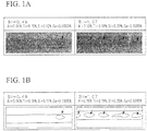
- FIG. 1A and FIG. 1B The results are shown in FIG. 1A and FIG. 1B .
- FIG. 1A is a photograph that shows an appearance of black spots generated in back side during TIG welding.
- FIG. 1B is a schematic drawing that shows an appearance of black spots generated in back side during TIG welding and that corresponds to FIG. 1A .
- FIG. 1A and FIG. 1B the left-side figures show a photograph and a drawing of test piece A in which BI value is 0.49, and the right-side figures show a photograph and a drawing of test piece B in which BI value is 1.07.
- a FE (Field Emission) Auger Electron Spectroscopy was used in the AES analysis, and the analysis was performed until intensity of oxygen spectrum was almost not detected under conditions of an acceleration voltage of 10keV, a spot diameter of 40 nm, and a sputtering rate of 15 nm/min. Although a position dependent error may occur due to small spot of AES measurement, the results were applied as values showing approximate thickness.
- FIG. 2A and FIG. 2B are graphs that show depth profile of elements (concentration distribution of elements in depth direction) in the black spot and the weld bead portion on the back side of the test piece as a result of AES analysis.
- FIG. 2A is a result of weld bead portion
- FIG. 2B is a result of a black spot.
- the weld bead portion was an oxide having a thickness of several hundred ⁇ that mainly contained Ti, and also contained Al and Si.
- the black spot was a thick oxide having a thickness of several thousand ⁇ that mainly contained Al, and also contained Ti, Si, and Ca. From the graph of black spot shown in FIG. 2B , it was confirmed that Al was contained in the black spot at the highest concentration and Ca was contained in the black spot at high concentration irrespective of its small amount in the steel.
- Test materials of ferritic stainless steel having various component ratios (compositions) were produced in accordance with the production method similar to that of test piece A, where each steel had a basic composition of C: 0.002 to 0.015%, N: 0.02 to 0.015%, Cr: 16.5 to 23%, Ni: 0 to 1.5%, Mo: 0 to 2.5%, and also contained main components of black spots such as Al, Ti, Si, and Ca in different amount. Using the test materials, a plurality of test pieces was obtained.
- test piece No. 1 The thus obtained plurality of test pieces were subjected to TIG welding under similar welding conditions as the test piece No. 1, and ratios of formation length of black spots were calculated in accordance with the same manner as the test piece No. 1.
- the formation length ratio of black spots tended to increase in accordance with the increasing amounts of Al, Ti, Si, and Ca. Those elements are elements having specifically strong affinity with oxygen. It was found that Al had the highest effect, and Ca had a strong influence on black spots irrespective of its small amount in the steel. It was also confirmed that Ti and Si also contributed to the generation of black spots.
- BI value shown by the below described formula 1 was calculated for the plurality of test pieces, and the relationship between the BI value and the ratio of formation length of black spots was examined.
- BI 3 ⁇ Al + Ti + 0.5 ⁇ Si + 200 ⁇ Ca ⁇ 0.8
- Al, Ti, Si, and Ca in the formula 1 respectively denotes an amount of each element in mass % of the steel.
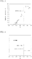
- FIG. 3 is a graph showing the relationship between the BI value and the ratio of formation length of black spots. As shown in FIG. 3 , it is recognized that the ratio of formation length of black spots increases with an increasing BI value.
- FIG. 4 is a graph that shows a relationship between the BI values and the results of corrosion resistance evaluation after the spray test after working.
- double circles (O) show excellent results
- circles ( ⁇ ) show good results
- crosses ( ⁇ ) show bad results.
- corrosion did not occur in the specimen with bulge height of 6 mm where BI value was 0.8 or less.
- BI value was 0.4 or less
- specifically good results were achieved such that corrosion was not observed in the specimen with bulge height of 7 mm.
- the ferritic stainless steel of the present invention can be appropriately used in members requiring corrosion resistance in a structure of, for example, exterior materials, building materials, water or hot water containers, consumer electronics, kitchen equipment, drain water collectors and heat exchanger of gas condensing boiler, various welded pipes or the like that are formed by TIG welding and used in general indoor or outdoor environment.
- the ferritic stainless steel of the present invention is appropriately used in a member that is subjected to working after the welding. Since the ferritic stainless steel of the present invention is excellent not only in corrosion resistance but also in workability of TIG weld zone, the steel can be widely used in the usage suffering severe working conditions.
Description
- The present invention relates to a ferritic stainless steel that generates only a small amount of black spots in the TIG weld zone.
- Ferritic stainless steel generally has properties such as a small expansion coefficient relative to the austenitic stainless steel and excellent resistance to stress corrosion cracking in addition to excellent corrosion resistance. Therefore, the ferritic stainless steel is widely used in tableware, kitchen equipment, building exterior materials such as roof materials, water or hot water container materials or the like. Further, there is increasing demand for replacement of austenitic stainless steel due to recent increasing price of nickel raw material, and the uses of ferritic stainless steel have expanded.
- Welding is an inevitable process in forming the above-described structure of stainless steel. Originally, ferritic stainless steel included a problem of sensitization in weld zone resulting in reduction of corrosion resistance due to the small solid-solubility limit of C and N. In order to solve the above-described problem, there has been proposed and widely practicalized a method of suppressing the sensitization of a weld metal zone by reduction of C and N contents, or by fixing of C and N by addition of stabilizing elements such as Ti and Nb, or the like (for example, see Patent Reference 1).
- The following have been known with regards to the corrosion resistance of weld zone in the ferritic stainless steel. Corrosion resistance is deteriorated in the scale portion generated by heat input during the welding, and therefore, it is important to perform sufficient shielding with an inert gas compared to the austenitic stainless steel. Patent Reference 2 discloses a technique of adding Ti and Al such that the formula, P1=5Ti+20(Al-0.01) ≥ 5 (wherein Ti and Al in the formula denote amounts of respective elements in the steel) is satisfied, thereby forming an Al oxide film on the surface portion of the steel during welding to improve corrosion resistance of the weld-heat affected zone.
- Patent Reference 3 discloses a technique of improving crevice corrosion resistance of the weld zone by adding a certain amount or more of Si in addition to combined addition of Al and Ti.
-
Patent Reference 4 discloses a technique to improve the corrosion resistance of a weld zone by satisfying 4Al + Ti ≤ 0.32 (wherein each of Ti and Al denotes amount of each component in the steel), thereby reducing heat input during the welding and suppressing generation of scale in the weld zone, and improving corrosion resistance of the weld zone. - The above-described prior arts have objects of improving corrosion resistance of the weld zone and weld heat affected zone.
- In another method, there is a technique to improve the weather resistance and crevice corrosion resistance of not the weld zone but the material itself by intentionally adding P and appropriate amounts of Ca and Al (for example, see Patent Reference 5). In Patent Reference 5, Ca and Al are added to control the shapes and distribution of non-metallic inclusions in the steel. The most important feature of Patent Reference 5 is the addition of P in excess of 0.04%, and Patent Reference 5 describes nothing about an effect during welding.
-
- Patent Reference 1: Japanese Examined Patent Application, Second Publication No.
S55-21102 - Patent Reference 2: Japanese Unexamined Patent Application, First Publication No.
H05-70899 - Patent Reference 3: Japanese Unexamined Patent Application, First Publication No.
2006-241564 - Patent Reference 4: Japanese Unexamined Patent Application, First Publication No.
2007-270290 - Patent Reference 5: Japanese Unexamined Patent Application, First Publication No.
H07-34205 -
JP 2006 263811 A - In the conventional ferritic stainless steel, dark spots (so called black spots or slag spots) occasionally occurred on the surfaces of back beads after the welding even though shielding conditions in the weld zone were controlled appropriately. Elements such as Al, Ti, Si, Ca have a strong affinity to oxygen. Black spots are oxides of these elements that are solidified on the surface of the weld metal during the solidification process of the weld metal formed by Tungsten Inert Gas (TIG) welding. Weld conditions, especially the conditions of shielding with the inert gas have a strong influence on the generation of the black spots. Many black spots occur where the shielding is insufficient.
- Since the black spot itself is an oxide, there is no problem in corrosion resistance and workability of the weld zone even when the weld zone is dotted with a small amount of black spots. However, where the black spots are generated in a large amount or generated in a continuously linked manner, the appearance of the weld material used without polishing the weld zone is worsened. In addition, exfoliation of the black spots portion occasionally occurs during working of the weld zone. Where the black spot portion is exfoliated, problems such as deterioration of workability and/or occurrence of crevice corrosion in the interstitial area between the weld metal and the exfoliated black spots occasionally occur. Even when the steel member is not worked after the welding, where a thick portion is formed by the black spots, exfoliation of the black spots and the resultant deterioration of corrosion resistance occasionally occur in the member having a structure in which stress is loaded on the weld zone.
- Therefore, in order to improve the corrosion resistance of the TIG weld zone, it is important to not only improve the corrosion resistance of the weld bead portion itself and weld scale portion itself, but also to control the occurrence of black spots in the weld zone. The scale that is generated during the welding and accompanies the change of color can be mostly suppressed by the method of enhancing shielding conditions during welding. However, the black spots generated in the TIG weld zone could not be suppressed sufficiently in accordance with the prior arts even when the shielding conditions were enhanced.
- In consideration of the above-explained circumstances, an object of the present invention is to provide a ferritic stainless steel that is resistant to the generation of black spots in the TIG weld zone and exhibits excellent corrosion resistance and workability in the weld zone.
- As described below, the inventors performed extensive research to suppress the amount of generation of black spots. As a result, the inventors found that the generation of black spots in the TIG weld zone could be suppressed by optimizing the amounts of Al, Ti, Si, and Ca, and reached the invention of the ferritic stainless steel in which black spots are generated only in a small amount.
- The invention is defined in the claims.
- According to the present invention, it is possible to provide a ferritic stainless steel in which black spots do not easily occur and that is excellent in corrosion resistance and workability of the weld zone.
-
-
FIG. 1A is a photograph that shows appearance of black spots that were generated in the back side during TIG welding. -
FIG. 1B is a schematic drawing that corresponds to the photograph ofFIG. 1A and shows an appearance of black spots that were generated in the back side during TIG welding. -
FIG. 2A is a graph that shows a result of AES measurement of depth profile of elements (concentration distributions of elements in the depth direction) of the weld bead portion in the back side of a test piece. -
FIG. 2B is a graph that shows a result of AES measurement of depth profile of elements (concentration distributions of elements in the depth direction) of a black spot in the back side of a test piece. -
FIG. 3 is a graph that shows a relationship between the BI value and the formation length ratio of black spots. -
FIG. 4 is a graph showing the relationship between the BI value and corrosion, where concentric double circles (⊚) show excellent results, circles (○ ) show good results, and crosses (×) show bad results. - In the following, the present invention is explained in detail.
- A ferritic stainless steel according to the present invention that generates only a small amount of black spot satisfies the below described formula 1.

- Al, Ti, Si, and Ca are elements that have a specifically strong affinity with oxygen and that generate black spots at the time of TIG welding. As the amount of Al, Ti, Si, and Ca contained in the steel increases, black spots are easily generated. The coefficients of the amounts of Al, Ti, Si, and Ca in the above-described formula 1 are determined based on the degree (strength) of the effect of enhancing the generation of black spots and the amounts in the steel. Specifically, as it is shown in the following experimental example, Al is an element that is included in the black spot at the highest concentration and has a specifically large effect of enhancing the generation of black spots. Therefore, coefficient of the Al content in the above-described formula 1 is determined to be 3.
- Ca is an element that is included in the black spot at a high concentration regardless of its small content in the steel and that has a large effect of enhancing the generation of black spots. Therefore, the coefficient of the Ca content is determined to be 200.
- Where the above-described BI value exceeds 0.8, the generation of black spots is prominent. On the other hand, where the BI value is 0.8 or less, the generation of black spots in the TIG weld zone is sufficiently reduced, and an excellent corrosion resistance is obtained. Where the BI value is 0.6 or less, it is possible to suppress the generation of black spots more effectively. Further, where the BI value is 0.4 or less, the generation of black spots is mostly suppressed, and it is possible to further improve the corrosion resistance of the TIG weld zone.
- Under conditions in which a large amount of black spots tend to occur, the black spot portion has a large thickness. It is considered that such a portion is easily exfoliated at the time of working, and that severe working such as bulging causes the exfoliation and provides a starting point for corrosion. On the contrary, the black spots have thin thickness under conditions in which black spots are generated in a small amount. Therefore, it is considered that even when black spots are generated, the black spots are not exfoliated easily. Therefore, it is considered that corrosion resistance of the weld zone can be suppressed by suppressing the generation of black spots.
- Next, component compositions of the ferritic stainless steel according to the present invention are explained in detail.
- Firstly, each of the elements for regulating the above described formula 1 is explained.
- Al is important as an deoxidizing element and has an effect in grain-refinement of the microstructure of the steel by controlling the composition of non-metallic inclusion. However, Al is an element that has the largest contribution to the generation of black spots. In addition, excessive addition of Al causes coarsening of the non-metallic inclusions that may act as starting points of scratching in the product. Therefore, the upper limit of the amount of Al was determined to be 0.12%. The steel contains 0.01% or more of Al with the purpose of deoxidization. More preferably, the amount of Al is 0.03% to 0.10%.
- Ti is an very important element for fixing C and N and suppressing grain boundary corrosion in the weld zone, thereby improving workability. However, excessive addition of Ti results in not only generation of black spots but also occurrence of surface scratches during the production process. Therefore, the range of the amount of Ti was determined to be 0.05% to 0.35%. More preferable range is 0.07% to 0.20%.
- Si is an important element as an deoxidizing element and is effective in improvement of corrosion resistance and oxidation resistance. However, excessive addition of Si results in not only enhancement of generation of black spots but also deterioration of workability and productivity. Therefore, the upper limit of the amount of Si was determined to be 1.0%. The steel contains 0.01% or more of Si for the purpose of deoxidization. Preferably, the amount of Si is 0.05% to 0.55%.
- Ca is very important as an deoxidizing element and is contained in the steel in small amount in the form of non-metallic inclusion. On the other hand, since Ca is oxidized very easily, Ca behaves as strong cause of generation of black spots in the time of welding. In addition, there is a case in that Ca causes generation of water-soluble inclusion, thereby deteriorating corrosion resistance. Therefore, it is preferable to control the amount of Ca to be as small as possible, and the upper limit of the amount of Ca was determined to be 0.0015%. More preferably, the amount of Ca is 0.0012% or less.
- Next, the other elements constituting the ferritic stainless steel according to the present invention is explained.
- The amount of C must be suppressed since C deteriorates grain boundary corrosion resistance and workability. Therefore the upper limit of C was determined to be 0.020%. On the other hand, excessive reduction of C causes an increase in the refining cost. Therefore, the amount of C is preferably 0.002% to 0.015%.
- In the same manner as C, N deteriorates grain boundary corrosion resistance and the workability of the steel. Therefore, it is necessary to reduce the amount of N. Therefore, upper limit of the amount of N was determined to be 0.025%. On the other hand, excessive reduction of N causes an increase in the refining cost. Therefore, the amount of N is preferably 0.002% to 0.015%.
- Although Mn is an important element as a deoxidizing element, excessive addition of Mn tends to cause generation of MnS that acts as a starting point of corrosion, and destabilizes the ferrite microstructure. Therefore, the amount of Mn was controlled to be 1.0% or less. For the purpose of deoxidization, the steel contains 0.01% or more of Mn. Preferably, the amount of Mn is 0.05% to 0.5%, and more preferably, 0.05% to 0.3%.
- The amount of P must be suppressed to low value since P deteriorates weldability and workability and makes the grain boundary corrosion easily occur. Therefore, the amount of P was controlled to be 0.035% or less. A more preferable amount of P is 0.001% to 0.02%.
- The amount of S must be reduced since S generates water-soluble inclusions such as CaS and MnS that act as starting points of corrosion. Therefore, the amount of S is controlled to be 0.01% or less. On the other hand, excessive reduction of S results in deterioration of the cost. Therefore, the amount of S is preferably 0.0001% to 0.005%.
- Cr is the most important element for ensuring corrosion resistance of the stainless steel. In order to stabilize the ferrite microstructure, it is necessary for the steel to contain 16.0% or more of Cr. On the other hand Cr deteriorates the workability and productivity of the steel. Therefore, the upper limit of Cr content was determined to be 25.0%. Preferably, the amount of Cr is 16.5% to 23.0%, and more preferably, 18.0% to 22.5%.
- Nb has properties such that Nb may be added alone, or in combination with Ti. Where Nb and Ti are added in combination, it is preferable that the formula: (Ti+Nb)/(C+N) ≥ 6 is satisfied, where Ti, Nb, C, and N in the formula each denote the amount in mass % of each element in the steel.
- In the same manner as Ti, Nb fixes C and N, suppress grain boundary corrosion of weld-zone, and improves workability. On the other hand, excessive addition of Nb deteriorates workability of the steel. Therefore, it is preferable to control the upper limit of the amount of Nb to be 0.6%. In order to improve the above-described properties by the content of Nb, it is preferable for the steel to contain 0.05% or more of Nb. Preferably, the amount of Nb is 0.15% to 0.55%.
- In the invention, the stainless steel sheet contains optionally one or more of 0.30 to 3.0% of Mo, 0.05 to 2.0% of Cn, 0.05 to 2.0% of Ni, 0.03 to 0.2% of V, 0.03 to 0.2% of Zr and 0.0001 to 0.005% of B.
- Mo is an element that has an effect of repairing the passive film and is very effective in improvement of corrosion resistance. By being added in combination with Cr, Mo has an effect of improving pitting corrosion resistance of the steel. By being added in combination with Ni, Mo has an effect of improving the resistance to outflow rust. On the other hand, increased Mo reduces workability and increases the cost. Therefore, if present, the upper limit of the amount of Mo is 3.0%. In order to improve the above-described properties by the content of Mo, if present, the steel contains 0.30% or more of Mo. Preferably, the amount of Mo is 0.60% to 2.5%, more preferably, 0.9% to 2.0%.
- Ni has an effect of suppressing active dissolution rate, and is excellent in repassivation properties because of the small hydrogen overvoltage. On the other hand, excessive addition of Ni deteriorates workability and destabilizes the ferrite microstructure. Therefore, if present, the upper limit of the amount of Ni is 2.0%. In order to improve the above-described properties by the content of Ni, if present, the steel contains 0.05% or more of Ni. Preferably, the amount of Ni is 0.1% to 1.2%, more preferably, 0.2% to 1.1%.
- In the same manner as Ni, Cu reduces the active dissolution rate, and has an effect of enhancing repassivation. However, an excessive addition of Cu deteriorates the workability. Therefore, where Cu is added, the upper limit of the amount is 2.0%. In order to improve the above-described property by the content of Cu, if present, steel contains 0.05% or more of Cu. Preferably, the amount of Cu is 0.2% to 1.5%, more preferably, 0.25% to 1.1%.
- V and Zr improve weather resistance and crevice corrosion resistance. In addition, where V is added while suppressing the use of Cr and Mo, it is possible to ensure an excellent workability. On the other hand, excessive addition of V and/or Zr deteriorates workability, and saturates the effect of improving corrosion resistance. Therefore, where V and/or Zr is contained, the upper limit of the amount is 0.2%. In order to improve the above-described properties by the content of V and/or Zr, the steel contains 0.03% or more of V and/or Zr. More preferably, the amount of V and/or Zr is 0.05% to 0.1%.
- B is an element that strengthens grain boundary and is effective in improvement of secondary working embrittlement. On the other hand, excessive addition of B causes reduction of ductility by solution-strengthening of ferrite. Therefore, where B is added, the lower limit is 0.0001%, and the upper limit is 0.005%. More preferably, the amount of B is controlled to be 0.0002% to 0.0020%.
- Test pieces composed of ferritic stainless steel each having a chemical component (composition) shown in Table 1 were produced in accordance with the below described method. Firstly, a cast steel having a chemical component (composition) shown in Table 1 was molten by vacuum melting, and an ingot having a thickness of 40 mm was produced from the melt. The ingot was rolled to a thickness of 5 mm by hot rolling. After that, in accordance with the recrystallization behavior of each steel, the rolled steel was heat treated for one minute at a temperature of 800 to 1000°C. After removing a scale by grinding, steel plates having a thickness of 0.8 mm were produced by cold rolling. After removing the surface oxide scale by pickling (acid cleaning), test materials were obtained. Using the test materials, test pieces of Nos. 1 to 28 were produced. In the chemical component (composition) shown in Table 1, the amount of each element is shown in mass %, and the balance is iron and unavoidable impurities. The under-line shows that the value is outside the range of the present invention.
Table 1 No. C Si Mn P S Cr Al Ti Ca N Mo Nb Ni Cu B V Zr Fe and unavoidable impurities 1 0.004 0.10 0.11 0.007 0.001 18.0 0.04 0.20 0.0002 0.008 Balance reference 2 0.005 0.11 0.20 0.015 0.003 18.2 0.06 0.12 0.0002 0.007 0.52 Balance reference 3 0.008 0.09 0.20 0.011 0.002 19.7 0.04 0.12 0.0003 0.012 0.20 Balance inventive 4 0.011 0.10 0.11 0.009 0.001 22.9 0.03 0.10 0.0003 0.010 0.31 0.05 Balance inventive 5 0.012 0.11 0.18 0.009 0.001 18.7 0.03 0.16 0.0004 0.011 1.81 0.28 Balance inventive 6 0.005 0.08 0.20 0.008 0.001 22.5 0.07 0.09 0.0002 0.008 1.18 0.18 Balance inventive 7 0.007 0.10 0.14 0.010 0.002 19.0 0.04 0.14 0.0004 0.010 0.99 0.22 Balance inventive 8 0.010 0.13 0.15 0.010 0.002 18.4 0.04 0.16 0.0002 0.010 1.90 0.23 0.12 0.20 0.10 Balance inventive 9 0.004 0.12 0.18 0.009 0.003 22.6 0.05 0.13 0.0003 0.011 0.82 0.25 0.15 0.15 0.08 Balance inventive 10 0.007 0.51 0.25 0.010 0.002 19.1 0.01 0.07 0.0002 0.009 0.45 0.28 0.44 Balance inventive 11 0.004 0.10 0.16 0.009 0.001 20.9 0.03 0.06 0.0002 0.009 0.25 0.0007 Balance inventive 12 0.007 0.12 0.25 0.010 0.002 19.1 0.06 0.12 0.0002 0.009 0.95 0.21 1.02 0.06 Balance inventive 13 0.014 0.04 0.22 0.020 0.003 17.5 0.04 0.08 0.0005 0.014 0.51 0.12 Balance inventive 14 0.003 0.45 0.27 0.011 0.002 19.4 0.05 0.09 0.0003 0.006 0.17 0.40 0.50 0.0004 0.12 Balance inventive 15 0.009 0.08 0.09 0.008 0.002 18.5 0.08 0.08 0.0004 0.008 0.55 Balance inventive 16 0.004 0.12 0.20 0.022 0.002 23.0 0.12 0.19 0.0002 0.008 0.55 Balance reference 17 0.005 0.15 0.21 0.020 0.003 19.2 0.04 0.30 0.0009 0.009 0.25 0.39 Balance reference 18 0.004 0.10 0.14 0.007 0.001 17.1 0.04 0.22 0.0003 0.009 Balance reference 19 0.004 0.12 0.12 0.008 0.003 23.7 0.06 0.15 0.0005 0.011 1.85 0.21 Balance inventive 20 0.013 0.62 0.25 0.020 0.003 17.6 0.06 0.07 0.0004 0.014 0.38 Balance inventive 21 0.005 0.09 0.28 0.015 0.002 23.8 0.08 0.21 0.0010 0.010 0.19 0.0008 0.09 Balance inventive 22 0.010 0.25 0.20 0.030 0.003 23.0 0.15 0.19 0.0015 0.012 0.22 Balance comparative 23 0.006 0.65 0.21 0.015 0.002 18.5 0.05 0.02 0.0010 0.009 0.41 0.25 0.39 Balance comparative 24 0.004 0.20 0.22 0.020 0.003 21.5 0.09 0.34 0.0010 0.010 1.05 0.11 Balance comparative 25 0.006 0.26 0.16 0.025 0.001 15.9 0.09 0.21 0.0009 0.014 0.0010 Balance comparative 26 0.010 0.25 0.20 0.020 0.002 17.9 0.03 0.40 0.0015 0.011 2.01 Balance comparative 27 0.015 1.01 0.31 0.002 0.002 18.0 0.04 0.19 0.0014 0.014 0.36 Balance comparative 28 0.012 0.28 0.23 0.018 0.003 23.5 0.10 0.21 0.0019 0.012 1.56 0.18 0.08 Balance comparative - The thus obtained test pieces of Nos. 1 to 28 were subjected to TIG welding under the following welding conditions, and formation length ratio of black spot was measured in accordance with the following manner. In addition, corrosion experiment was performed for the test piece of Nos. 1 to 28.
- Pieces of the same steel were butted and subjected to TIG welding with feed rate of 50 cm/min, and heat input of 550 to 650J/cm2. Argon was used both in shielding of torch side and shielding of back side.
- The formation length ratio of black spots was determined as a standard for showing the amount of generated black spots after the TIG welding. The formation length ratio of black spots was obtained by integrating length of each black spot along the welding direction, and dividing the integrated value by the total welding length. Practically, photograph of a 10 cm length weld zone was taken by a digital camera, length of each black spot was measured, and ratio of the integrated length of black spots to the welding length was calculated using image processing.
- TIG weld zones of test pieces were subjected to bulging and were used as test pieces for corrosion test. Erichsen test conditions in accordance with JIS2247 were used as the bulging conditions. The penetration side was used as the surface, and a punch of 20 mm φ was used in the bulging. The working of each test piece was paused so as to adjust the working conditions with respect to the height of the bulge. The paused height (height of bulge) was standardized to 6 mm and 7 mm. Each test piece was subjected to continuous spray test of 5%NaCl in accordance with JIS Z 2371, and corrosion was evaluated by presence or absence of outflow rust in the test piece at 48 hours after the spray test. Where the outflow rust was not observed in the bulged test piece with bulging height of 6 mm after the continuous spray test of 5%NaCl, the result was evaluated as "GOOD". Where the outflow rust was not observed in the bulged test piece with bulging height of 7 mm after the same spray test, the result was evaluated as "EXCELLENT". Where the outflow rust occurred after the continuous spray test, the result was evaluated as BAD.
- BI values determined from the chemical component in Table 1, formation length ratio of black spots, and the results of corrosion test are shown in Table 2.
Table 2 No. BI Formation length ratio of black spots (%) Results of corrosion test 1 0.40 10 EXCELLENT reference 2 0.40 7 EXCELLENT reference 3 0.35 3 EXCELLENT inventive 4 0.30 0 EXCELLENT inventive 5 0.39 9 EXCELLENT inventive 6 0.38 7 EXCELLENT inventive 7 0.39 9 EXCELLENT inventive 8 0.39 10 EXCELLENT inventive 9 0.40 8 EXCELLENT inventive 10 0.40 9 EXCELLENT inventive 11 0.24 0 EXCELLENT inventive 12 0.40 9 EXCELLENT inventive 13 0.32 7 EXCELLENT inventive 14 0.53 22 GOOD inventive 15 0.44 15 GOOD inventive 16 0.65 41 GOOD reference 17 0.68 49 GOOD reference 18 0.45 19 GOOD reference 19 0.49 20 GOOD inventive 20 0.64 39 GOOD inventive 21 0.70 45 GOOD inventive 22 1.07 78 BAD comparative 23 0.70 45 BAD comparative 24 0.91 86 BAD comparative 25 0.79 60 BAD comparative 26 0.92 89 BAD comparative 27 1.10 83 BAD comparative 28 1.03 88 BAD comparative - As shown in Table 2, formation length ratios of black spots were small, that is, amounts of generated black spots after the TIG welding were small in the test pieces Nos. 1 to 15, 19 to 21 that had chemical component (composition) within the range of the present invention and BI value of 0.8 or less. Generation of black spots was suppressed in the test pieces No. 1 to 15 having a BI value of 0.6 or less. Further, generation of black spots was mostly suppressed in Nos. 1 to 13 having a BI value of 0.4 or less such that the ratio of formation length of black spots was 10% or less. In test pieces No. 1 to 21 which were worked to have a bulge height of 6mm using an Erichsen test machine, rust from the weld zone was not observed after the continuous spray test of 5%NaCl. In test pieces No. 1 to 21 which were more severely worked to have a bulge height of 7mm, rust was not observed in test pieces having BI value of 0.4 or less, and rust was observed in test pieces having BI value exceeding 0.4.
- On the other hand, the test pieces Nos. 22, 24, 26 to 28 having BI value exceeding 0.8 showed large formation length ratio of black spots after the TIG welding and rust from the weld zone was observed in each specimen in the corrosion test. Magnified images of rust portions of test pieces Nos. 22, 24, 26 to 28 were observed using a magnifying glass. As a result, exfoliation was observed in the boundary between the black spots and the weld bead portion. Rust was generated in corrosion test of Nos. 22, 26, 27, and 28 in which concentrations of Al, Ti, Si, and Ca exceeded the regulated values. Occurrence of rust was observed in the corrosion test of the test piece No. 25 in which component ratio of Cr was less than 16% and the test piece No. 23 in which component ratio of Ti was less than 0.05%.
- Experimental example 1, not within the scope of the present invention.
- Test materials were produced in accordance with the same manner as test piece No.1 except for that steel plates of 1 mm thick were produced by cold-rolling of ferritic stainless steels having the below described chemical components (compositions). Test piece A and test piece B were obtained using the test materials.
- C: 0.007%, N: 0.011%, Si: 0.12%, Mn: 0.18%, P: 0.22%, S: 0.001%, Cr: 19.4%, Al 0.06%, Ti: 0.15%, Ca: 0.000,5%, balance: iron and unavoidable impurities.
- C: 0.009%, N: 0.010%. Si: 0.25%. Mn: 0.15%, P: 0.21%, S: 0.001%, Cr: 20.2%, Al: 0.15%, Ti: 0.19%, Ca: 0.0015%, balance: iron and unavoidable impurities.
- The thus obtained test piece A and test piece B were subjected to TIG welding under the similar welding conditions as the test piece No. 1, and appearance of black spots generated in the back side during TIG welding was observed.
- The results are shown in
FIG. 1A and FIG. 1B . -
FIG. 1A is a photograph that shows an appearance of black spots generated in back side during TIG welding.FIG. 1B is a schematic drawing that shows an appearance of black spots generated in back side during TIG welding and that corresponds toFIG. 1A . - In
FIG. 1A and FIG. 1B , the left-side figures show a photograph and a drawing of test piece A in which BI value is 0.49, and the right-side figures show a photograph and a drawing of test piece B in which BI value is 1.07. - As shown by the arrows in
FIG. 1A and FIG. 1B , spot-like black spots are observed dispersingly both in the test piece A with BI value of 0.49 and test piece B with BI value of 1.07. However, it is recognized that the black spots are generated in larger amount in test piece B (right-side photograph) having a larger BI value. - Two portions selected from the weld bead portion and the black spot portion of the test piece B with a BI value of 1.07 were subjected to auger electron spectroscopy (AES). The results are shown in
FIG. 2A and FIG. 2B . - A FE (Field Emission) Auger Electron Spectroscopy was used in the AES analysis, and the analysis was performed until intensity of oxygen spectrum was almost not detected under conditions of an acceleration voltage of 10keV, a spot diameter of 40 nm, and a sputtering rate of 15 nm/min. Although a position dependent error may occur due to small spot of AES measurement, the results were applied as values showing approximate thickness.
-
FIG. 2A and FIG. 2B are graphs that show depth profile of elements (concentration distribution of elements in depth direction) in the black spot and the weld bead portion on the back side of the test piece as a result of AES analysis.FIG. 2A is a result of weld bead portion, andFIG. 2B is a result of a black spot. - As shown in
FIG. 2A . the weld bead portion was an oxide having a thickness of several hundred Å that mainly contained Ti, and also contained Al and Si. On the other hand, as shown inFIG. 2B , the black spot was a thick oxide having a thickness of several thousand Å that mainly contained Al, and also contained Ti, Si, and Ca. From the graph of black spot shown inFIG. 2B , it was confirmed that Al was contained in the black spot at the highest concentration and Ca was contained in the black spot at high concentration irrespective of its small amount in the steel. - Test materials of ferritic stainless steel having various component ratios (compositions) were produced in accordance with the production method similar to that of test piece A, where each steel had a basic composition of C: 0.002 to 0.015%, N: 0.02 to 0.015%, Cr: 16.5 to 23%, Ni: 0 to 1.5%, Mo: 0 to 2.5%, and also contained main components of black spots such as Al, Ti, Si, and Ca in different amount. Using the test materials, a plurality of test pieces was obtained.
- The thus obtained plurality of test pieces were subjected to TIG welding under similar welding conditions as the test piece No. 1, and ratios of formation length of black spots were calculated in accordance with the same manner as the test piece No. 1.
- As a result, the formation length ratio of black spots tended to increase in accordance with the increasing amounts of Al, Ti, Si, and Ca. Those elements are elements having specifically strong affinity with oxygen. It was found that Al had the highest effect, and Ca had a strong influence on black spots irrespective of its small amount in the steel. It was also confirmed that Ti and Si also contributed to the generation of black spots.
- Based on the results, it was found that there was a strong possibility of generation of black spots even under shielding conditions where large amounts of Al, Ti, Si, and Ca were added, and that Al and Ti had strong influence on generation of black spots.
- BI value shown by the below described formula 1 was calculated for the plurality of test pieces, and the relationship between the BI value and the ratio of formation length of black spots was examined.

- The results are shown in
FIG. 3. FIG. 3 is a graph showing the relationship between the BI value and the ratio of formation length of black spots. As shown inFIG. 3 , it is recognized that the ratio of formation length of black spots increases with an increasing BI value. - Each of the plurality of test pieces was subjected to corrosion test in accordance with the same manner as the test piece No. 1. The results are shown in
FIG. 4. FIG. 4 is a graph that shows a relationship between the BI values and the results of corrosion resistance evaluation after the spray test after working. In the figure, double circles (Ⓞ) show excellent results, circles ( ○) show good results, and crosses (×) show bad results. As shown inFIG. 4 , corrosion did not occur in the specimen with bulge height of 6 mm where BI value was 0.8 or less. Especially, where BI value was 0.4 or less, specifically good results were achieved such that corrosion was not observed in the specimen with bulge height of 7 mm. - The ferritic stainless steel of the present invention can be appropriately used in members requiring corrosion resistance in a structure of, for example, exterior materials, building materials, water or hot water containers, consumer electronics, kitchen equipment, drain water collectors and heat exchanger of gas condensing boiler, various welded pipes or the like that are formed by TIG welding and used in general indoor or outdoor environment. Specifically, the ferritic stainless steel of the present invention is appropriately used in a member that is subjected to working after the welding. Since the ferritic stainless steel of the present invention is excellent not only in corrosion resistance but also in workability of TIG weld zone, the steel can be widely used in the usage suffering severe working conditions.
Claims (10)
- A ferritic stainless steel for being welded by TIG welding consisting of, in mass %,0.002 to 0.020 % of C,0.002 to 0.025% of N,0.01 to 1.0% of Si,0.01 to 1.0% of Mn,0.001 to 0.035% of P,0.0001 to 0.01% of S,16.0 to 25.0% of Cr,0.01 to 0.12% of Al,0.05 to 0.35% of Ti,0.05 to 0.6% of Nb,present up to 0.0015% of Ca, and optionally one or more of 0.30 to 3.0 % of Mo, 0.05 to 2.0 % of Cu, 0.05 to 2.0 % of Ni,0.03 to 0.2% of V, 0.03 to 0.2% Zr and 0.0001 to 0.005% of B,the balance consisting of Fe and unavoidable impurities, wherein the following formula 1 is satisfied,
 where Al, Ti, Si, and Ca in the formula 1 each denotes an amount of each element in mass % of the steel.
 - A ferritic stainless steel according to claim 1, containing, in mass %, 0.30 to 3.0% of Mo.
- A ferritic stainless steel according to claim 1 or 2, containing, in mass %, one or two selected from 0.05 to 2.0% of Cu and 0.05 to 2.0% of Ni.
- A ferritic stainless steel according to claim 1 or 2, containing, in mass %, one or two selected from 0.03 to 0.2% of V and 0.03 to 0.2% of Zr.
- A ferritic stainless steel according to claim 3, containing, in mass %, one or two selected from 0.03 to 0.2% of V and 0.03 to 0.2% of Zr.
- A ferritic stainless steel according to claim 1 or 2, containing, in mass %, 0.0001 to 0.005% of B.
- A ferritic stainless steel according to claim 3, containing, in mass %, 0.005% of B.
- A ferritic stainless steel according to claim 4, containing, in mass %, 0.0001 to 0.005% of B.
- A ferritic stainless steel according to claim 5, containing, in mass %, 0.0001 to 0.005% of B.
- Use of a ferritic stainless steel according to any one of claims 1 to 9 in members being welded by TIG welding.
Applications Claiming Priority (2)
| Application Number | Priority Date | Filing Date | Title |
|---|---|---|---|
| JP2010177998A JP5793283B2 (en) | 2010-08-06 | 2010-08-06 | Ferritic stainless steel with few black spots |
| PCT/JP2011/067850 WO2012018074A1 (en) | 2010-08-06 | 2011-08-04 | Ferritic stainless steel |
Publications (3)
| Publication Number | Publication Date |
|---|---|
| EP2602351A1 EP2602351A1 (en) | 2013-06-12 |
| EP2602351A4 EP2602351A4 (en) | 2017-04-05 |
| EP2602351B1 true EP2602351B1 (en) | 2019-10-02 |
Family
ID=45559570
Family Applications (1)
| Application Number | Title | Priority Date | Filing Date |
|---|---|---|---|
| EP11814699.2A Active EP2602351B1 (en) | 2010-08-06 | 2011-08-04 | Ferritic stainless steel |
Country Status (8)
| Country | Link |
|---|---|
| US (1) | US20130129560A1 (en) |
| EP (1) | EP2602351B1 (en) |
| JP (1) | JP5793283B2 (en) |
| KR (1) | KR20130034042A (en) |
| CN (1) | CN103052731A (en) |
| AU (1) | AU2011286685A1 (en) |
| TW (1) | TWI526549B (en) |
| WO (1) | WO2012018074A1 (en) |
Families Citing this family (18)
| Publication number | Priority date | Publication date | Assignee | Title |
|---|---|---|---|---|
| JP6071608B2 (en) | 2012-03-09 | 2017-02-01 | 新日鐵住金ステンレス株式会社 | Ferritic stainless steel plate with excellent oxidation resistance |
| JP5793459B2 (en) | 2012-03-30 | 2015-10-14 | 新日鐵住金ステンレス株式会社 | Heat-resistant ferritic stainless steel cold-rolled steel sheet excellent in workability, ferritic stainless hot-rolled steel sheet for cold-rolled material, and production method thereof |
| FI124995B (en) * | 2012-11-20 | 2015-04-15 | Outokumpu Oy | Ferritic stainless steel |
| WO2014087648A1 (en) * | 2012-12-07 | 2014-06-12 | Jfeスチール株式会社 | Ferritic stainless steel sheet |
| MX2015013765A (en) | 2013-03-27 | 2016-02-26 | Nippon Steel & Sumikin Sst | Hot-rolled ferritic stainless-steel plate, process for producing same, and steel strip. |
| JP5987821B2 (en) * | 2013-12-27 | 2016-09-07 | Jfeスチール株式会社 | Ferritic stainless steel |
| JP5935792B2 (en) * | 2013-12-27 | 2016-06-15 | Jfeスチール株式会社 | Ferritic stainless steel |
| US10272513B2 (en) * | 2014-07-31 | 2019-04-30 | Jfe Steel Corporation | Ferritic stainless steel sheet for plasma arc welding and welding method therefor |
| US20190106775A1 (en) * | 2016-03-29 | 2019-04-11 | Jfe Steel Corporation | Ferritic stainless steel sheet |
| ES2835273T3 (en) * | 2016-06-27 | 2021-06-22 | Jfe Steel Corp | Ferritic stainless steel sheet |
| CN109563596A (en) * | 2016-09-02 | 2019-04-02 | 杰富意钢铁株式会社 | Ferrite-group stainless steel |
| WO2018043309A1 (en) | 2016-09-02 | 2018-03-08 | Jfeスチール株式会社 | Ferritic stainless steel |
| JP2019044255A (en) * | 2017-09-07 | 2019-03-22 | Jfeスチール株式会社 | Ferritic stainless steel sheet |
| JP7042057B2 (en) | 2017-10-25 | 2022-03-25 | 日鉄ステンレス株式会社 | Stainless steel materials and welded structural members with excellent slag spot generation suppression ability and their manufacturing methods |
| TWI801538B (en) * | 2018-03-27 | 2023-05-11 | 日商日鐵不銹鋼股份有限公司 | Ferritic stainless steel, method for producing the same, ferritic stainless steel sheet, method for producing the same, and members for fuel cell |
| ES2927078T3 (en) * | 2018-12-21 | 2022-11-02 | Outokumpu Oy | ferritic stainless steel |
| JP7118015B2 (en) * | 2019-01-16 | 2022-08-15 | 日鉄ステンレス株式会社 | Method for predicting and evaluating the amount of slag spots generated in stainless steel |
| KR102326044B1 (en) * | 2019-12-20 | 2021-11-15 | 주식회사 포스코 | Ferritic stainless steel with improved magnetization properties and manufacturing method thereof |
Family Cites Families (22)
| Publication number | Priority date | Publication date | Assignee | Title |
|---|---|---|---|---|
| JPS5188413A (en) | 1975-02-01 | 1976-08-03 | Kotaishokuseifueraitosutenresuko | |
| JP2739531B2 (en) * | 1991-09-17 | 1998-04-15 | 日新製鋼株式会社 | Ferritic stainless steel with excellent weld corrosion resistance |
| JP2880906B2 (en) | 1993-05-19 | 1999-04-12 | 川崎製鉄株式会社 | Ferritic stainless steel with excellent weather resistance and crevice corrosion resistance |
| JPH08144021A (en) * | 1994-11-18 | 1996-06-04 | Sumitomo Metal Ind Ltd | Production of ferritic stainless steel and cold rolled sheet therefrom |
| JPH1012212A (en) * | 1996-06-18 | 1998-01-16 | Yuasa Corp | Sealed lead acid battery |
| JPH10102212A (en) * | 1996-09-30 | 1998-04-21 | Kawasaki Steel Corp | Ferritic stainless steel sheet excellent in penetration at welding |
| JP3190290B2 (en) * | 1997-09-26 | 2001-07-23 | 日新製鋼株式会社 | Ferritic stainless steel with excellent corrosion resistance at welds |
| JP4465853B2 (en) * | 2000-10-30 | 2010-05-26 | Jfeスチール株式会社 | Ferritic stainless steel cold rolled steel for jar pot containers and ferritic stainless steel containers for jar pots with excellent corrosion resistance and scale adhesion |
| JP3976660B2 (en) * | 2002-10-10 | 2007-09-19 | 新日鐵住金ステンレス株式会社 | Chromium-containing steel for container material, welding method thereof, and container material |
| JP4025171B2 (en) * | 2002-10-29 | 2007-12-19 | 日本冶金工業株式会社 | Stainless steel having excellent corrosion resistance, weldability and surface properties and method for producing the same |
| JP4397772B2 (en) * | 2004-09-24 | 2010-01-13 | 新日鐵住金ステンレス株式会社 | Manufacturing method of ferritic stainless steel sheet with excellent workability |
| JP4784239B2 (en) * | 2005-02-28 | 2011-10-05 | Jfeスチール株式会社 | Ferritic stainless steel filler rod for TIG welding |
| JP2006241564A (en) | 2005-03-07 | 2006-09-14 | Nisshin Steel Co Ltd | Ferritic stainless steel for welded structure |
| JP5119605B2 (en) * | 2006-03-31 | 2013-01-16 | Jfeスチール株式会社 | Ferritic stainless steel with excellent corrosion resistance of welds |
| JP5010323B2 (en) * | 2006-04-10 | 2012-08-29 | 日新製鋼株式会社 | Ferritic stainless steel for hot water container with welded structure, hot water container and manufacturing method thereof |
| WO2008084838A1 (en) * | 2007-01-12 | 2008-07-17 | Jfe Steel Corporation | Ferritic stainless steel sheet for water heater excellent in corrosion resistance at welded part and steel sheet toughness |
| JP5010301B2 (en) * | 2007-02-02 | 2012-08-29 | 日新製鋼株式会社 | Ferritic stainless steel for exhaust gas path member and exhaust gas path member |
| JP5111910B2 (en) * | 2007-03-23 | 2013-01-09 | 新日鐵住金ステンレス株式会社 | Ferritic stainless steel with low surface defects and excellent weldability and crevice corrosion resistance |
| JP2009091654A (en) * | 2007-09-18 | 2009-04-30 | Jfe Steel Kk | Ferritic stainless steel having excellent weldability |
| JP4651682B2 (en) * | 2008-01-28 | 2011-03-16 | 新日鐵住金ステンレス株式会社 | High purity ferritic stainless steel with excellent corrosion resistance and workability and method for producing the same |
| JP5305289B2 (en) | 2009-01-29 | 2013-10-02 | 日本電信電話株式会社 | User authentication method, user authentication system, user terminal, user authentication device, user terminal program, and user authentication device program |
| JP5489759B2 (en) * | 2009-02-09 | 2014-05-14 | 新日鐵住金ステンレス株式会社 | Ferritic stainless steel with few black spots |
-
2010
- 2010-08-06 JP JP2010177998A patent/JP5793283B2/en active Active
-
2011
- 2011-08-04 US US13/813,511 patent/US20130129560A1/en not_active Abandoned
- 2011-08-04 CN CN2011800382369A patent/CN103052731A/en active Pending
- 2011-08-04 EP EP11814699.2A patent/EP2602351B1/en active Active
- 2011-08-04 AU AU2011286685A patent/AU2011286685A1/en not_active Abandoned
- 2011-08-04 WO PCT/JP2011/067850 patent/WO2012018074A1/en active Application Filing
- 2011-08-04 KR KR1020137003262A patent/KR20130034042A/en not_active Application Discontinuation
- 2011-08-04 TW TW100127716A patent/TWI526549B/en active
Non-Patent Citations (1)
| Title |
|---|
| None * |
Also Published As
| Publication number | Publication date |
|---|---|
| TWI526549B (en) | 2016-03-21 |
| JP5793283B2 (en) | 2015-10-14 |
| KR20130034042A (en) | 2013-04-04 |
| EP2602351A1 (en) | 2013-06-12 |
| CN103052731A (en) | 2013-04-17 |
| TW201213559A (en) | 2012-04-01 |
| WO2012018074A1 (en) | 2012-02-09 |
| AU2011286685A1 (en) | 2013-02-28 |
| US20130129560A1 (en) | 2013-05-23 |
| EP2602351A4 (en) | 2017-04-05 |
| JP2012036444A (en) | 2012-02-23 |
Similar Documents
| Publication | Publication Date | Title |
|---|---|---|
| EP2602351B1 (en) | Ferritic stainless steel | |
| EP2395121B1 (en) | Ferrite stainless steel with low black spot generation | |
| EP3438310B1 (en) | Ferritic stainless steel sheet used for tig welding | |
| EP3029170B1 (en) | Ferrite-martensite dual-phase stainless steel, and method for producing same | |
| EP2787097B1 (en) | Ferritic stainless steel | |
| KR20090087072A (en) | Ferritic stainless steel sheet for water heater excellent in corrosion resistance at welded part and steel sheet toughness | |
| EP2799577B1 (en) | Ferritic stainless steel | |
| WO2014119189A1 (en) | Coated electrode | |
| EP3647452A1 (en) | Steel sheet having excellent resistance to liquid metal embrittlement cracks and method for manufacturing same | |
| US8900380B2 (en) | Low-chromium stainless steel excellent in corrosion resistance of weld | |
| TW201207128A (en) | Structural stainless steel sheet having excellent corrosion resistance at weld and method for manufacturing same | |
| EP3901292A1 (en) | Cr-based stainless steel having excellent hydrogen embrittlement resistance | |
| JP3247244B2 (en) | Fe-Cr-Ni alloy with excellent corrosion resistance and workability | |
| US7429302B2 (en) | Stainless steel sheet for welded structural components and method for making the same | |
| JP6354772B2 (en) | Ferritic stainless steel | |
| JP5012194B2 (en) | Ferritic stainless steel sheet for water heater with high welded joint strength and manufacturing method thereof | |
| WO2021201122A1 (en) | Welded structure and storage tank | |
| JP6262893B1 (en) | Ferritic stainless steel and welded structures | |
| JPH0641697A (en) | Fe-cr alloy excellent in corrosion resistance |
Legal Events
| Date | Code | Title | Description |
|---|---|---|---|
| PUAI | Public reference made under article 153(3) epc to a published international application that has entered the european phase |
Free format text: ORIGINAL CODE: 0009012 |
|
| 17P | Request for examination filed |
Effective date: 20130305 |
|
| AK | Designated contracting states |
Kind code of ref document: A1 Designated state(s): AL AT BE BG CH CY CZ DE DK EE ES FI FR GB GR HR HU IE IS IT LI LT LU LV MC MK MT NL NO PL PT RO RS SE SI SK SM TR |
|
| DAX | Request for extension of the european patent (deleted) | ||
| RA4 | Supplementary search report drawn up and despatched (corrected) |
Effective date: 20170306 |
|
| RIC1 | Information provided on ipc code assigned before grant |
Ipc: C22C 38/24 20060101ALI20170228BHEP Ipc: C22C 38/06 20060101ALI20170228BHEP Ipc: C22C 38/40 20060101ALI20170228BHEP Ipc: C22C 38/28 20060101ALI20170228BHEP Ipc: C22C 38/20 20060101ALI20170228BHEP Ipc: C22C 38/26 20060101ALI20170228BHEP Ipc: C21D 8/02 20060101ALI20170228BHEP Ipc: C22C 38/00 20060101AFI20170228BHEP Ipc: F28F 21/08 20060101ALI20170228BHEP Ipc: C22C 38/22 20060101ALI20170228BHEP Ipc: C21D 6/00 20060101ALI20170228BHEP Ipc: C22C 38/02 20060101ALI20170228BHEP Ipc: C22C 38/04 20060101ALI20170228BHEP Ipc: C22C 38/42 20060101ALI20170228BHEP |
|
| REG | Reference to a national code |
Ref country code: DE Ref legal event code: R079 Ref document number: 602011062497 Country of ref document: DE Free format text: PREVIOUS MAIN CLASS: C22C0038280000 Ipc: C22C0038000000 |
|
| GRAP | Despatch of communication of intention to grant a patent |
Free format text: ORIGINAL CODE: EPIDOSNIGR1 |
|
| STAA | Information on the status of an ep patent application or granted ep patent |
Free format text: STATUS: GRANT OF PATENT IS INTENDED |
|
| RIC1 | Information provided on ipc code assigned before grant |
Ipc: C22C 38/26 20060101ALI20190208BHEP Ipc: C22C 38/24 20060101ALI20190208BHEP Ipc: C22C 38/28 20060101ALI20190208BHEP Ipc: C21D 8/02 20060101ALI20190208BHEP Ipc: C22C 38/22 20060101ALI20190208BHEP Ipc: C22C 38/40 20060101ALI20190208BHEP Ipc: C21D 6/00 20060101ALI20190208BHEP Ipc: C22C 38/04 20060101ALI20190208BHEP Ipc: C22C 38/42 20060101ALI20190208BHEP Ipc: C22C 38/00 20060101AFI20190208BHEP Ipc: C22C 38/02 20060101ALI20190208BHEP Ipc: C22C 38/06 20060101ALI20190208BHEP Ipc: C22C 38/20 20060101ALI20190208BHEP Ipc: F28F 21/08 20060101ALI20190208BHEP |
|
| INTG | Intention to grant announced |
Effective date: 20190226 |
|
| GRAS | Grant fee paid |
Free format text: ORIGINAL CODE: EPIDOSNIGR3 |
|
| GRAJ | Information related to disapproval of communication of intention to grant by the applicant or resumption of examination proceedings by the epo deleted |
Free format text: ORIGINAL CODE: EPIDOSDIGR1 |
|
| GRAL | Information related to payment of fee for publishing/printing deleted |
Free format text: ORIGINAL CODE: EPIDOSDIGR3 |
|
| STAA | Information on the status of an ep patent application or granted ep patent |
Free format text: STATUS: REQUEST FOR EXAMINATION WAS MADE |
|
| GRAR | Information related to intention to grant a patent recorded |
Free format text: ORIGINAL CODE: EPIDOSNIGR71 |
|
| STAA | Information on the status of an ep patent application or granted ep patent |
Free format text: STATUS: GRANT OF PATENT IS INTENDED |
|
| INTC | Intention to grant announced (deleted) | ||
| GRAA | (expected) grant |
Free format text: ORIGINAL CODE: 0009210 |
|
| STAA | Information on the status of an ep patent application or granted ep patent |
Free format text: STATUS: THE PATENT HAS BEEN GRANTED |
|
| INTG | Intention to grant announced |
Effective date: 20190730 |
|
| AK | Designated contracting states |
Kind code of ref document: B1 Designated state(s): AL AT BE BG CH CY CZ DE DK EE ES FI FR GB GR HR HU IE IS IT LI LT LU LV MC MK MT NL NO PL PT RO RS SE SI SK SM TR |
|
| REG | Reference to a national code |
Ref country code: GB Ref legal event code: FG4D |
|
| REG | Reference to a national code |
Ref country code: CH Ref legal event code: EP Ref country code: AT Ref legal event code: REF Ref document number: 1186239 Country of ref document: AT Kind code of ref document: T Effective date: 20191015 |
|
| REG | Reference to a national code |
Ref country code: DE Ref legal event code: R096 Ref document number: 602011062497 Country of ref document: DE |
|
| REG | Reference to a national code |
Ref country code: IE Ref legal event code: FG4D |
|
| REG | Reference to a national code |
Ref country code: SE Ref legal event code: TRGR |
|
| REG | Reference to a national code |
Ref country code: NL Ref legal event code: MP Effective date: 20191002 |
|
| REG | Reference to a national code |
Ref country code: LT Ref legal event code: MG4D |
|
| REG | Reference to a national code |
Ref country code: AT Ref legal event code: MK05 Ref document number: 1186239 Country of ref document: AT Kind code of ref document: T Effective date: 20191002 |
|
| PG25 | Lapsed in a contracting state [announced via postgrant information from national office to epo] |
Ref country code: PT Free format text: LAPSE BECAUSE OF FAILURE TO SUBMIT A TRANSLATION OF THE DESCRIPTION OR TO PAY THE FEE WITHIN THE PRESCRIBED TIME-LIMIT Effective date: 20200203 Ref country code: BG Free format text: LAPSE BECAUSE OF FAILURE TO SUBMIT A TRANSLATION OF THE DESCRIPTION OR TO PAY THE FEE WITHIN THE PRESCRIBED TIME-LIMIT Effective date: 20200102 Ref country code: GR Free format text: LAPSE BECAUSE OF FAILURE TO SUBMIT A TRANSLATION OF THE DESCRIPTION OR TO PAY THE FEE WITHIN THE PRESCRIBED TIME-LIMIT Effective date: 20200103 Ref country code: PL Free format text: LAPSE BECAUSE OF FAILURE TO SUBMIT A TRANSLATION OF THE DESCRIPTION OR TO PAY THE FEE WITHIN THE PRESCRIBED TIME-LIMIT Effective date: 20191002 Ref country code: NO Free format text: LAPSE BECAUSE OF FAILURE TO SUBMIT A TRANSLATION OF THE DESCRIPTION OR TO PAY THE FEE WITHIN THE PRESCRIBED TIME-LIMIT Effective date: 20200102 Ref country code: LV Free format text: LAPSE BECAUSE OF FAILURE TO SUBMIT A TRANSLATION OF THE DESCRIPTION OR TO PAY THE FEE WITHIN THE PRESCRIBED TIME-LIMIT Effective date: 20191002 Ref country code: ES Free format text: LAPSE BECAUSE OF FAILURE TO SUBMIT A TRANSLATION OF THE DESCRIPTION OR TO PAY THE FEE WITHIN THE PRESCRIBED TIME-LIMIT Effective date: 20191002 Ref country code: NL Free format text: LAPSE BECAUSE OF FAILURE TO SUBMIT A TRANSLATION OF THE DESCRIPTION OR TO PAY THE FEE WITHIN THE PRESCRIBED TIME-LIMIT Effective date: 20191002 Ref country code: LT Free format text: LAPSE BECAUSE OF FAILURE TO SUBMIT A TRANSLATION OF THE DESCRIPTION OR TO PAY THE FEE WITHIN THE PRESCRIBED TIME-LIMIT Effective date: 20191002 Ref country code: AT Free format text: LAPSE BECAUSE OF FAILURE TO SUBMIT A TRANSLATION OF THE DESCRIPTION OR TO PAY THE FEE WITHIN THE PRESCRIBED TIME-LIMIT Effective date: 20191002 |
|
| PG25 | Lapsed in a contracting state [announced via postgrant information from national office to epo] |
Ref country code: CZ Free format text: LAPSE BECAUSE OF FAILURE TO SUBMIT A TRANSLATION OF THE DESCRIPTION OR TO PAY THE FEE WITHIN THE PRESCRIBED TIME-LIMIT Effective date: 20191002 Ref country code: IS Free format text: LAPSE BECAUSE OF FAILURE TO SUBMIT A TRANSLATION OF THE DESCRIPTION OR TO PAY THE FEE WITHIN THE PRESCRIBED TIME-LIMIT Effective date: 20200224 Ref country code: HR Free format text: LAPSE BECAUSE OF FAILURE TO SUBMIT A TRANSLATION OF THE DESCRIPTION OR TO PAY THE FEE WITHIN THE PRESCRIBED TIME-LIMIT Effective date: 20191002 Ref country code: RS Free format text: LAPSE BECAUSE OF FAILURE TO SUBMIT A TRANSLATION OF THE DESCRIPTION OR TO PAY THE FEE WITHIN THE PRESCRIBED TIME-LIMIT Effective date: 20191002 |
|
| PG25 | Lapsed in a contracting state [announced via postgrant information from national office to epo] |
Ref country code: AL Free format text: LAPSE BECAUSE OF FAILURE TO SUBMIT A TRANSLATION OF THE DESCRIPTION OR TO PAY THE FEE WITHIN THE PRESCRIBED TIME-LIMIT Effective date: 20191002 |
|
| REG | Reference to a national code |
Ref country code: DE Ref legal event code: R097 Ref document number: 602011062497 Country of ref document: DE |
|
| PG2D | Information on lapse in contracting state deleted |
Ref country code: IS |
|
| PG25 | Lapsed in a contracting state [announced via postgrant information from national office to epo] |
Ref country code: DK Free format text: LAPSE BECAUSE OF FAILURE TO SUBMIT A TRANSLATION OF THE DESCRIPTION OR TO PAY THE FEE WITHIN THE PRESCRIBED TIME-LIMIT Effective date: 20191002 Ref country code: EE Free format text: LAPSE BECAUSE OF FAILURE TO SUBMIT A TRANSLATION OF THE DESCRIPTION OR TO PAY THE FEE WITHIN THE PRESCRIBED TIME-LIMIT Effective date: 20191002 Ref country code: RO Free format text: LAPSE BECAUSE OF FAILURE TO SUBMIT A TRANSLATION OF THE DESCRIPTION OR TO PAY THE FEE WITHIN THE PRESCRIBED TIME-LIMIT Effective date: 20191002 Ref country code: IS Free format text: LAPSE BECAUSE OF FAILURE TO SUBMIT A TRANSLATION OF THE DESCRIPTION OR TO PAY THE FEE WITHIN THE PRESCRIBED TIME-LIMIT Effective date: 20200202 |
|
| PLBE | No opposition filed within time limit |
Free format text: ORIGINAL CODE: 0009261 |
|
| STAA | Information on the status of an ep patent application or granted ep patent |
Free format text: STATUS: NO OPPOSITION FILED WITHIN TIME LIMIT |
|
| PG25 | Lapsed in a contracting state [announced via postgrant information from national office to epo] |
Ref country code: SM Free format text: LAPSE BECAUSE OF FAILURE TO SUBMIT A TRANSLATION OF THE DESCRIPTION OR TO PAY THE FEE WITHIN THE PRESCRIBED TIME-LIMIT Effective date: 20191002 Ref country code: SK Free format text: LAPSE BECAUSE OF FAILURE TO SUBMIT A TRANSLATION OF THE DESCRIPTION OR TO PAY THE FEE WITHIN THE PRESCRIBED TIME-LIMIT Effective date: 20191002 |
|
| 26N | No opposition filed |
Effective date: 20200703 |
|
| PG25 | Lapsed in a contracting state [announced via postgrant information from national office to epo] |
Ref country code: SI Free format text: LAPSE BECAUSE OF FAILURE TO SUBMIT A TRANSLATION OF THE DESCRIPTION OR TO PAY THE FEE WITHIN THE PRESCRIBED TIME-LIMIT Effective date: 20191002 |
|
| PG25 | Lapsed in a contracting state [announced via postgrant information from national office to epo] |
Ref country code: MC Free format text: LAPSE BECAUSE OF FAILURE TO SUBMIT A TRANSLATION OF THE DESCRIPTION OR TO PAY THE FEE WITHIN THE PRESCRIBED TIME-LIMIT Effective date: 20191002 |
|
| REG | Reference to a national code |
Ref country code: CH Ref legal event code: PL |
|
| GBPC | Gb: european patent ceased through non-payment of renewal fee |
Effective date: 20200804 |
|
| PG25 | Lapsed in a contracting state [announced via postgrant information from national office to epo] |
Ref country code: CH Free format text: LAPSE BECAUSE OF NON-PAYMENT OF DUE FEES Effective date: 20200831 Ref country code: LI Free format text: LAPSE BECAUSE OF NON-PAYMENT OF DUE FEES Effective date: 20200831 Ref country code: LU Free format text: LAPSE BECAUSE OF NON-PAYMENT OF DUE FEES Effective date: 20200804 |
|
| REG | Reference to a national code |
Ref country code: BE Ref legal event code: MM Effective date: 20200831 |
|
| REG | Reference to a national code |
Ref country code: FI Ref legal event code: PCE Owner name: NIPPON STEEL STAINLESS STEEL CORPORATION |
|
| REG | Reference to a national code |
Ref country code: DE Ref legal event code: R081 Ref document number: 602011062497 Country of ref document: DE Owner name: NIPPON STEEL STAINLESS STEEL CORPORATION, JP Free format text: FORMER OWNER: NIPPON STEEL & SUMIKIN STAINLESS STEEL CORPORATION, TOKYO, JP |
|
| PG25 | Lapsed in a contracting state [announced via postgrant information from national office to epo] |
Ref country code: BE Free format text: LAPSE BECAUSE OF NON-PAYMENT OF DUE FEES Effective date: 20200831 Ref country code: IE Free format text: LAPSE BECAUSE OF NON-PAYMENT OF DUE FEES Effective date: 20200804 Ref country code: GB Free format text: LAPSE BECAUSE OF NON-PAYMENT OF DUE FEES Effective date: 20200804 |
|
| PG25 | Lapsed in a contracting state [announced via postgrant information from national office to epo] |
Ref country code: TR Free format text: LAPSE BECAUSE OF FAILURE TO SUBMIT A TRANSLATION OF THE DESCRIPTION OR TO PAY THE FEE WITHIN THE PRESCRIBED TIME-LIMIT Effective date: 20191002 Ref country code: MT Free format text: LAPSE BECAUSE OF FAILURE TO SUBMIT A TRANSLATION OF THE DESCRIPTION OR TO PAY THE FEE WITHIN THE PRESCRIBED TIME-LIMIT Effective date: 20191002 Ref country code: CY Free format text: LAPSE BECAUSE OF FAILURE TO SUBMIT A TRANSLATION OF THE DESCRIPTION OR TO PAY THE FEE WITHIN THE PRESCRIBED TIME-LIMIT Effective date: 20191002 |
|
| PG25 | Lapsed in a contracting state [announced via postgrant information from national office to epo] |
Ref country code: MK Free format text: LAPSE BECAUSE OF FAILURE TO SUBMIT A TRANSLATION OF THE DESCRIPTION OR TO PAY THE FEE WITHIN THE PRESCRIBED TIME-LIMIT Effective date: 20191002 |
|
| PGFP | Annual fee paid to national office [announced via postgrant information from national office to epo] |
Ref country code: IT Payment date: 20230811 Year of fee payment: 13 Ref country code: FI Payment date: 20230808 Year of fee payment: 13 |
|
| PGFP | Annual fee paid to national office [announced via postgrant information from national office to epo] |
Ref country code: SE Payment date: 20230815 Year of fee payment: 13 Ref country code: FR Payment date: 20230811 Year of fee payment: 13 Ref country code: DE Payment date: 20230830 Year of fee payment: 13 |