EP2602341B1 - Grain-oriented electrical steel sheet, and method for producing same - Google Patents
Grain-oriented electrical steel sheet, and method for producing same Download PDFInfo
- Publication number
- EP2602341B1 EP2602341B1 EP11814304.9A EP11814304A EP2602341B1 EP 2602341 B1 EP2602341 B1 EP 2602341B1 EP 11814304 A EP11814304 A EP 11814304A EP 2602341 B1 EP2602341 B1 EP 2602341B1
- Authority
- EP
- European Patent Office
- Prior art keywords
- steel sheet
- forsterite film
- electron beam
- oriented electrical
- concentrated
- Prior art date
- Legal status (The legal status is an assumption and is not a legal conclusion. Google has not performed a legal analysis and makes no representation as to the accuracy of the status listed.)
- Active
Links
- 229910001224 Grain-oriented electrical steel Inorganic materials 0.000 title claims description 44
- 238000004519 manufacturing process Methods 0.000 title claims description 13
- 229910000831 Steel Inorganic materials 0.000 claims description 139
- 239000010959 steel Substances 0.000 claims description 139
- 229910052839 forsterite Inorganic materials 0.000 claims description 70
- HCWCAKKEBCNQJP-UHFFFAOYSA-N magnesium orthosilicate Chemical compound [Mg+2].[Mg+2].[O-][Si]([O-])([O-])[O-] HCWCAKKEBCNQJP-UHFFFAOYSA-N 0.000 claims description 69
- 238000010894 electron beam technology Methods 0.000 claims description 58
- 230000005381 magnetic domain Effects 0.000 claims description 41
- 238000000034 method Methods 0.000 claims description 23
- 230000001133 acceleration Effects 0.000 claims description 21
- 230000001747 exhibiting effect Effects 0.000 claims description 7
- 230000001678 irradiating effect Effects 0.000 claims description 7
- 239000000523 sample Substances 0.000 claims description 4
- XEEYBQQBJWHFJM-UHFFFAOYSA-N Iron Chemical compound [Fe] XEEYBQQBJWHFJM-UHFFFAOYSA-N 0.000 description 75
- CPLXHLVBOLITMK-UHFFFAOYSA-N Magnesium oxide Chemical compound [Mg]=O CPLXHLVBOLITMK-UHFFFAOYSA-N 0.000 description 50
- 230000000694 effects Effects 0.000 description 36
- 229910052742 iron Inorganic materials 0.000 description 36
- 238000000137 annealing Methods 0.000 description 32
- 238000000576 coating method Methods 0.000 description 27
- 239000003112 inhibitor Substances 0.000 description 26
- 239000000395 magnesium oxide Substances 0.000 description 25
- 239000002585 base Substances 0.000 description 23
- 239000011248 coating agent Substances 0.000 description 19
- 239000011669 selenium Substances 0.000 description 19
- 238000012360 testing method Methods 0.000 description 14
- 238000009826 distribution Methods 0.000 description 13
- 238000005096 rolling process Methods 0.000 description 12
- 239000000126 substance Substances 0.000 description 11
- 238000002474 experimental method Methods 0.000 description 10
- 238000001953 recrystallisation Methods 0.000 description 10
- 229910052711 selenium Inorganic materials 0.000 description 10
- 229910052717 sulfur Inorganic materials 0.000 description 10
- 230000015572 biosynthetic process Effects 0.000 description 9
- 239000000463 material Substances 0.000 description 9
- PXHVJJICTQNCMI-UHFFFAOYSA-N nickel Substances [Ni] PXHVJJICTQNCMI-UHFFFAOYSA-N 0.000 description 9
- 230000001603 reducing effect Effects 0.000 description 8
- 239000011572 manganese Substances 0.000 description 7
- OKTJSMMVPCPJKN-UHFFFAOYSA-N Carbon Chemical compound [C] OKTJSMMVPCPJKN-UHFFFAOYSA-N 0.000 description 6
- 229910052782 aluminium Inorganic materials 0.000 description 6
- 229910052799 carbon Inorganic materials 0.000 description 6
- 239000010960 cold rolled steel Substances 0.000 description 6
- 150000001875 compounds Chemical class 0.000 description 4
- 229910052748 manganese Inorganic materials 0.000 description 4
- 239000000203 mixture Substances 0.000 description 4
- 229910000976 Electrical steel Inorganic materials 0.000 description 3
- PWHULOQIROXLJO-UHFFFAOYSA-N Manganese Chemical compound [Mn] PWHULOQIROXLJO-UHFFFAOYSA-N 0.000 description 3
- VYPSYNLAJGMNEJ-UHFFFAOYSA-N Silicium dioxide Chemical compound O=[Si]=O VYPSYNLAJGMNEJ-UHFFFAOYSA-N 0.000 description 3
- 229910052784 alkaline earth metal Inorganic materials 0.000 description 3
- ILRRQNADMUWWFW-UHFFFAOYSA-K aluminium phosphate Chemical compound O1[Al]2OP1(=O)O2 ILRRQNADMUWWFW-UHFFFAOYSA-K 0.000 description 3
- 229910052787 antimony Inorganic materials 0.000 description 3
- 229910052804 chromium Inorganic materials 0.000 description 3
- 239000008119 colloidal silica Substances 0.000 description 3
- 229910052802 copper Inorganic materials 0.000 description 3
- 239000013078 crystal Substances 0.000 description 3
- 238000005261 decarburization Methods 0.000 description 3
- 230000004907 flux Effects 0.000 description 3
- 238000010438 heat treatment Methods 0.000 description 3
- 239000012535 impurity Substances 0.000 description 3
- 238000011835 investigation Methods 0.000 description 3
- 229910052750 molybdenum Inorganic materials 0.000 description 3
- 229910052759 nickel Inorganic materials 0.000 description 3
- 229910052758 niobium Inorganic materials 0.000 description 3
- 229910052757 nitrogen Inorganic materials 0.000 description 3
- 229910052698 phosphorus Inorganic materials 0.000 description 3
- 230000008569 process Effects 0.000 description 3
- 239000000047 product Substances 0.000 description 3
- XUIMIQQOPSSXEZ-UHFFFAOYSA-N Silicon Chemical compound [Si] XUIMIQQOPSSXEZ-UHFFFAOYSA-N 0.000 description 2
- 238000009825 accumulation Methods 0.000 description 2
- 229910052791 calcium Inorganic materials 0.000 description 2
- 230000008859 change Effects 0.000 description 2
- 238000005097 cold rolling Methods 0.000 description 2
- 238000000354 decomposition reaction Methods 0.000 description 2
- 230000006866 deterioration Effects 0.000 description 2
- 230000002542 deteriorative effect Effects 0.000 description 2
- 150000002500 ions Chemical class 0.000 description 2
- 229910052749 magnesium Inorganic materials 0.000 description 2
- 239000011777 magnesium Substances 0.000 description 2
- 238000013507 mapping Methods 0.000 description 2
- 238000005259 measurement Methods 0.000 description 2
- 230000000704 physical effect Effects 0.000 description 2
- 238000000746 purification Methods 0.000 description 2
- 229910052710 silicon Inorganic materials 0.000 description 2
- 239000010703 silicon Substances 0.000 description 2
- 238000002791 soaking Methods 0.000 description 2
- 229910052712 strontium Inorganic materials 0.000 description 2
- 239000002344 surface layer Substances 0.000 description 2
- 229910052718 tin Inorganic materials 0.000 description 2
- BUGBHKTXTAQXES-UHFFFAOYSA-N Selenium Chemical compound [Se] BUGBHKTXTAQXES-UHFFFAOYSA-N 0.000 description 1
- NINIDFKCEFEMDL-UHFFFAOYSA-N Sulfur Chemical compound [S] NINIDFKCEFEMDL-UHFFFAOYSA-N 0.000 description 1
- 239000000654 additive Substances 0.000 description 1
- 230000002411 adverse Effects 0.000 description 1
- 230000032683 aging Effects 0.000 description 1
- XAGFODPZIPBFFR-UHFFFAOYSA-N aluminium Chemical compound [Al] XAGFODPZIPBFFR-UHFFFAOYSA-N 0.000 description 1
- 229910052788 barium Inorganic materials 0.000 description 1
- 229910052794 bromium Inorganic materials 0.000 description 1
- 238000006243 chemical reaction Methods 0.000 description 1
- 230000000052 comparative effect Effects 0.000 description 1
- 239000011162 core material Substances 0.000 description 1
- 238000005098 hot rolling Methods 0.000 description 1
- 230000006872 improvement Effects 0.000 description 1
- 238000002347 injection Methods 0.000 description 1
- 239000007924 injection Substances 0.000 description 1
- 239000011229 interlayer Substances 0.000 description 1
- GVALZJMUIHGIMD-UHFFFAOYSA-H magnesium phosphate Chemical compound [Mg+2].[Mg+2].[Mg+2].[O-]P([O-])([O-])=O.[O-]P([O-])([O-])=O GVALZJMUIHGIMD-UHFFFAOYSA-H 0.000 description 1
- 229910000157 magnesium phosphate Inorganic materials 0.000 description 1
- 239000004137 magnesium phosphate Substances 0.000 description 1
- 229960002261 magnesium phosphate Drugs 0.000 description 1
- 235000010994 magnesium phosphates Nutrition 0.000 description 1
- 230000005415 magnetization Effects 0.000 description 1
- 229910052751 metal Inorganic materials 0.000 description 1
- 239000002184 metal Substances 0.000 description 1
- 150000003013 phosphoric acid derivatives Chemical class 0.000 description 1
- 239000002244 precipitate Substances 0.000 description 1
- 239000002987 primer (paints) Substances 0.000 description 1
- 230000035484 reaction time Effects 0.000 description 1
- 230000009467 reduction Effects 0.000 description 1
- 239000000243 solution Substances 0.000 description 1
- 239000011593 sulfur Substances 0.000 description 1
- 229910052719 titanium Inorganic materials 0.000 description 1
- 239000010936 titanium Substances 0.000 description 1
Images


Classifications
-
- H—ELECTRICITY
- H01—ELECTRIC ELEMENTS
- H01F—MAGNETS; INDUCTANCES; TRANSFORMERS; SELECTION OF MATERIALS FOR THEIR MAGNETIC PROPERTIES
- H01F1/00—Magnets or magnetic bodies characterised by the magnetic materials therefor; Selection of materials for their magnetic properties
- H01F1/01—Magnets or magnetic bodies characterised by the magnetic materials therefor; Selection of materials for their magnetic properties of inorganic materials
-
- C—CHEMISTRY; METALLURGY
- C21—METALLURGY OF IRON
- C21D—MODIFYING THE PHYSICAL STRUCTURE OF FERROUS METALS; GENERAL DEVICES FOR HEAT TREATMENT OF FERROUS OR NON-FERROUS METALS OR ALLOYS; MAKING METAL MALLEABLE, e.g. BY DECARBURISATION OR TEMPERING
- C21D8/00—Modifying the physical properties by deformation combined with, or followed by, heat treatment
- C21D8/12—Modifying the physical properties by deformation combined with, or followed by, heat treatment during manufacturing of articles with special electromagnetic properties
- C21D8/1244—Modifying the physical properties by deformation combined with, or followed by, heat treatment during manufacturing of articles with special electromagnetic properties the heat treatment(s) being of interest
- C21D8/1255—Modifying the physical properties by deformation combined with, or followed by, heat treatment during manufacturing of articles with special electromagnetic properties the heat treatment(s) being of interest with diffusion of elements, e.g. decarburising, nitriding
-
- C—CHEMISTRY; METALLURGY
- C21—METALLURGY OF IRON
- C21D—MODIFYING THE PHYSICAL STRUCTURE OF FERROUS METALS; GENERAL DEVICES FOR HEAT TREATMENT OF FERROUS OR NON-FERROUS METALS OR ALLOYS; MAKING METAL MALLEABLE, e.g. BY DECARBURISATION OR TEMPERING
- C21D9/00—Heat treatment, e.g. annealing, hardening, quenching or tempering, adapted for particular articles; Furnaces therefor
- C21D9/46—Heat treatment, e.g. annealing, hardening, quenching or tempering, adapted for particular articles; Furnaces therefor for sheet metals
-
- C—CHEMISTRY; METALLURGY
- C22—METALLURGY; FERROUS OR NON-FERROUS ALLOYS; TREATMENT OF ALLOYS OR NON-FERROUS METALS
- C22C—ALLOYS
- C22C38/00—Ferrous alloys, e.g. steel alloys
-
- C—CHEMISTRY; METALLURGY
- C22—METALLURGY; FERROUS OR NON-FERROUS ALLOYS; TREATMENT OF ALLOYS OR NON-FERROUS METALS
- C22C—ALLOYS
- C22C38/00—Ferrous alloys, e.g. steel alloys
- C22C38/002—Ferrous alloys, e.g. steel alloys containing In, Mg, or other elements not provided for in one single group C22C38/001 - C22C38/60
-
- C—CHEMISTRY; METALLURGY
- C22—METALLURGY; FERROUS OR NON-FERROUS ALLOYS; TREATMENT OF ALLOYS OR NON-FERROUS METALS
- C22C—ALLOYS
- C22C38/00—Ferrous alloys, e.g. steel alloys
- C22C38/18—Ferrous alloys, e.g. steel alloys containing chromium
- C22C38/34—Ferrous alloys, e.g. steel alloys containing chromium with more than 1.5% by weight of silicon
-
- C—CHEMISTRY; METALLURGY
- C22—METALLURGY; FERROUS OR NON-FERROUS ALLOYS; TREATMENT OF ALLOYS OR NON-FERROUS METALS
- C22C—ALLOYS
- C22C38/00—Ferrous alloys, e.g. steel alloys
- C22C38/18—Ferrous alloys, e.g. steel alloys containing chromium
- C22C38/40—Ferrous alloys, e.g. steel alloys containing chromium with nickel
- C22C38/42—Ferrous alloys, e.g. steel alloys containing chromium with nickel with copper
-
- C—CHEMISTRY; METALLURGY
- C22—METALLURGY; FERROUS OR NON-FERROUS ALLOYS; TREATMENT OF ALLOYS OR NON-FERROUS METALS
- C22C—ALLOYS
- C22C38/00—Ferrous alloys, e.g. steel alloys
- C22C38/18—Ferrous alloys, e.g. steel alloys containing chromium
- C22C38/40—Ferrous alloys, e.g. steel alloys containing chromium with nickel
- C22C38/44—Ferrous alloys, e.g. steel alloys containing chromium with nickel with molybdenum or tungsten
-
- C—CHEMISTRY; METALLURGY
- C22—METALLURGY; FERROUS OR NON-FERROUS ALLOYS; TREATMENT OF ALLOYS OR NON-FERROUS METALS
- C22C—ALLOYS
- C22C38/00—Ferrous alloys, e.g. steel alloys
- C22C38/18—Ferrous alloys, e.g. steel alloys containing chromium
- C22C38/40—Ferrous alloys, e.g. steel alloys containing chromium with nickel
- C22C38/48—Ferrous alloys, e.g. steel alloys containing chromium with nickel with niobium or tantalum
-
- C—CHEMISTRY; METALLURGY
- C23—COATING METALLIC MATERIAL; COATING MATERIAL WITH METALLIC MATERIAL; CHEMICAL SURFACE TREATMENT; DIFFUSION TREATMENT OF METALLIC MATERIAL; COATING BY VACUUM EVAPORATION, BY SPUTTERING, BY ION IMPLANTATION OR BY CHEMICAL VAPOUR DEPOSITION, IN GENERAL; INHIBITING CORROSION OF METALLIC MATERIAL OR INCRUSTATION IN GENERAL
- C23C—COATING METALLIC MATERIAL; COATING MATERIAL WITH METALLIC MATERIAL; SURFACE TREATMENT OF METALLIC MATERIAL BY DIFFUSION INTO THE SURFACE, BY CHEMICAL CONVERSION OR SUBSTITUTION; COATING BY VACUUM EVAPORATION, BY SPUTTERING, BY ION IMPLANTATION OR BY CHEMICAL VAPOUR DEPOSITION, IN GENERAL
- C23C26/00—Coating not provided for in groups C23C2/00 - C23C24/00
-
- C—CHEMISTRY; METALLURGY
- C23—COATING METALLIC MATERIAL; COATING MATERIAL WITH METALLIC MATERIAL; CHEMICAL SURFACE TREATMENT; DIFFUSION TREATMENT OF METALLIC MATERIAL; COATING BY VACUUM EVAPORATION, BY SPUTTERING, BY ION IMPLANTATION OR BY CHEMICAL VAPOUR DEPOSITION, IN GENERAL; INHIBITING CORROSION OF METALLIC MATERIAL OR INCRUSTATION IN GENERAL
- C23C—COATING METALLIC MATERIAL; COATING MATERIAL WITH METALLIC MATERIAL; SURFACE TREATMENT OF METALLIC MATERIAL BY DIFFUSION INTO THE SURFACE, BY CHEMICAL CONVERSION OR SUBSTITUTION; COATING BY VACUUM EVAPORATION, BY SPUTTERING, BY ION IMPLANTATION OR BY CHEMICAL VAPOUR DEPOSITION, IN GENERAL
- C23C30/00—Coating with metallic material characterised only by the composition of the metallic material, i.e. not characterised by the coating process
-
- H—ELECTRICITY
- H01—ELECTRIC ELEMENTS
- H01F—MAGNETS; INDUCTANCES; TRANSFORMERS; SELECTION OF MATERIALS FOR THEIR MAGNETIC PROPERTIES
- H01F1/00—Magnets or magnetic bodies characterised by the magnetic materials therefor; Selection of materials for their magnetic properties
- H01F1/01—Magnets or magnetic bodies characterised by the magnetic materials therefor; Selection of materials for their magnetic properties of inorganic materials
- H01F1/03—Magnets or magnetic bodies characterised by the magnetic materials therefor; Selection of materials for their magnetic properties of inorganic materials characterised by their coercivity
- H01F1/12—Magnets or magnetic bodies characterised by the magnetic materials therefor; Selection of materials for their magnetic properties of inorganic materials characterised by their coercivity of soft-magnetic materials
- H01F1/14—Magnets or magnetic bodies characterised by the magnetic materials therefor; Selection of materials for their magnetic properties of inorganic materials characterised by their coercivity of soft-magnetic materials metals or alloys
- H01F1/147—Alloys characterised by their composition
- H01F1/14766—Fe-Si based alloys
- H01F1/14775—Fe-Si based alloys in the form of sheets
-
- H—ELECTRICITY
- H01—ELECTRIC ELEMENTS
- H01F—MAGNETS; INDUCTANCES; TRANSFORMERS; SELECTION OF MATERIALS FOR THEIR MAGNETIC PROPERTIES
- H01F1/00—Magnets or magnetic bodies characterised by the magnetic materials therefor; Selection of materials for their magnetic properties
- H01F1/01—Magnets or magnetic bodies characterised by the magnetic materials therefor; Selection of materials for their magnetic properties of inorganic materials
- H01F1/03—Magnets or magnetic bodies characterised by the magnetic materials therefor; Selection of materials for their magnetic properties of inorganic materials characterised by their coercivity
- H01F1/12—Magnets or magnetic bodies characterised by the magnetic materials therefor; Selection of materials for their magnetic properties of inorganic materials characterised by their coercivity of soft-magnetic materials
- H01F1/14—Magnets or magnetic bodies characterised by the magnetic materials therefor; Selection of materials for their magnetic properties of inorganic materials characterised by their coercivity of soft-magnetic materials metals or alloys
- H01F1/16—Magnets or magnetic bodies characterised by the magnetic materials therefor; Selection of materials for their magnetic properties of inorganic materials characterised by their coercivity of soft-magnetic materials metals or alloys in the form of sheets
-
- B—PERFORMING OPERATIONS; TRANSPORTING
- B21—MECHANICAL METAL-WORKING WITHOUT ESSENTIALLY REMOVING MATERIAL; PUNCHING METAL
- B21B—ROLLING OF METAL
- B21B3/00—Rolling materials of special alloys so far as the composition of the alloy requires or permits special rolling methods or sequences ; Rolling of aluminium, copper, zinc or other non-ferrous metals
- B21B3/02—Rolling special iron alloys, e.g. stainless steel
-
- C—CHEMISTRY; METALLURGY
- C22—METALLURGY; FERROUS OR NON-FERROUS ALLOYS; TREATMENT OF ALLOYS OR NON-FERROUS METALS
- C22C—ALLOYS
- C22C38/00—Ferrous alloys, e.g. steel alloys
- C22C38/001—Ferrous alloys, e.g. steel alloys containing N
-
- C—CHEMISTRY; METALLURGY
- C22—METALLURGY; FERROUS OR NON-FERROUS ALLOYS; TREATMENT OF ALLOYS OR NON-FERROUS METALS
- C22C—ALLOYS
- C22C38/00—Ferrous alloys, e.g. steel alloys
- C22C38/008—Ferrous alloys, e.g. steel alloys containing tin
-
- C—CHEMISTRY; METALLURGY
- C22—METALLURGY; FERROUS OR NON-FERROUS ALLOYS; TREATMENT OF ALLOYS OR NON-FERROUS METALS
- C22C—ALLOYS
- C22C38/00—Ferrous alloys, e.g. steel alloys
- C22C38/02—Ferrous alloys, e.g. steel alloys containing silicon
-
- C—CHEMISTRY; METALLURGY
- C22—METALLURGY; FERROUS OR NON-FERROUS ALLOYS; TREATMENT OF ALLOYS OR NON-FERROUS METALS
- C22C—ALLOYS
- C22C38/00—Ferrous alloys, e.g. steel alloys
- C22C38/04—Ferrous alloys, e.g. steel alloys containing manganese
-
- C—CHEMISTRY; METALLURGY
- C22—METALLURGY; FERROUS OR NON-FERROUS ALLOYS; TREATMENT OF ALLOYS OR NON-FERROUS METALS
- C22C—ALLOYS
- C22C38/00—Ferrous alloys, e.g. steel alloys
- C22C38/06—Ferrous alloys, e.g. steel alloys containing aluminium
-
- C—CHEMISTRY; METALLURGY
- C22—METALLURGY; FERROUS OR NON-FERROUS ALLOYS; TREATMENT OF ALLOYS OR NON-FERROUS METALS
- C22C—ALLOYS
- C22C38/00—Ferrous alloys, e.g. steel alloys
- C22C38/08—Ferrous alloys, e.g. steel alloys containing nickel
-
- C—CHEMISTRY; METALLURGY
- C22—METALLURGY; FERROUS OR NON-FERROUS ALLOYS; TREATMENT OF ALLOYS OR NON-FERROUS METALS
- C22C—ALLOYS
- C22C38/00—Ferrous alloys, e.g. steel alloys
- C22C38/12—Ferrous alloys, e.g. steel alloys containing tungsten, tantalum, molybdenum, vanadium, or niobium
-
- C—CHEMISTRY; METALLURGY
- C22—METALLURGY; FERROUS OR NON-FERROUS ALLOYS; TREATMENT OF ALLOYS OR NON-FERROUS METALS
- C22C—ALLOYS
- C22C38/00—Ferrous alloys, e.g. steel alloys
- C22C38/16—Ferrous alloys, e.g. steel alloys containing copper
-
- C—CHEMISTRY; METALLURGY
- C22—METALLURGY; FERROUS OR NON-FERROUS ALLOYS; TREATMENT OF ALLOYS OR NON-FERROUS METALS
- C22C—ALLOYS
- C22C38/00—Ferrous alloys, e.g. steel alloys
- C22C38/18—Ferrous alloys, e.g. steel alloys containing chromium
-
- C—CHEMISTRY; METALLURGY
- C22—METALLURGY; FERROUS OR NON-FERROUS ALLOYS; TREATMENT OF ALLOYS OR NON-FERROUS METALS
- C22C—ALLOYS
- C22C38/00—Ferrous alloys, e.g. steel alloys
- C22C38/60—Ferrous alloys, e.g. steel alloys containing lead, selenium, tellurium, or antimony, or more than 0.04% by weight of sulfur
Definitions
- the present invention relates to a grain oriented electrical steel sheet having excellent iron loss properties, for use in an iron core material of a transformer or the like.
- a grain oriented electrical steel sheet is mainly utilized as an iron core of a transformer and required to exhibit excellent magnetization characteristics, e.g. low iron loss in particular.
- it is important to highly accord secondary recrystallized grains of a steel sheet with (110)[001] orientation, i.e. what is called "Goss orientation", and reduce impurities in a product steel sheet.
- Uss orientation secondary recrystallized grains of a steel sheet with (110)[001] orientation
- impurities in a product steel sheet there are limits on controlling crystal grain orientations and reducing impurities in view of production cost. Accordingly, there have been developed techniques for iron loss reduction, which is to apply non-uniformity (strain) to a surface of a steel sheet physically to subdivide magnetic domain width, i.e. magnetic domain refinement techniques.
- Patent Literature 1 proposes a technique of irradiating a steel sheet after final annealing with laser to introduce high-dislocation density regions into a surface layer of the steel sheet, thereby narrowing magnetic domain widths and reducing iron loss of the steel sheet.
- Patent Literature 2 proposes for actual implementation a technique of controlling magnetic domain widths by irradiating a steel sheet with plasma flame.
- Patent Literature 4 discloses the use of electron beam treatment for magnetic domain refinement.
- a manufacturing process of a grain oriented electrical steel sheet generally involves secondary recrystallization of steel facilitated by use of precipitates such as MnS, MnSe, AlN and the like referred to as "inhibitors".
- a grain oriented electrical steel sheet thus manufactured by using inhibitors has a primer coating referred to as “forsterite” (coating mainly composed of Mg 2 SiO 4 ) on a surface thereof and an insulating tension coating is often formed on this forsterite film.
- An insulating tension coating formed on forsterite film is useful in terms of reducing iron loss of the steel sheet, as well as causing a good effect on the base steel subjected to magnetic domain refinement described above.
- Patent Literature 3 discloses in connection with characteristics of forsterite film that characteristics of forsterite film improve and thus a grain oriented electrical steel sheet having excellent film properties can be manufactured by using, as annealing separator during final annealing, magnesia of which expected value in distribution of activity has been controllably set to be within a range of specific standard deviation.
- Patent Literature 3 discloses that magnesia generally includes low-activity component, intermediate-activity component, and high-activity component and that good magnetic properties and formation of satisfactorily hard film of a steel sheet can be achieved in a compatible manner by adjusting chemical composition, including these three types of components, of magnesia such that magnesia collectively meets adequate activity distribution ⁇ (A) and adequate standard deviation ⁇ (A), respectively.
- Patent Literature 3 also discloses that decomposition of inhibitors is suppressed when the annealing separator contains alkali earth metal ions such as Ca, Sr, Br or the like. There is a known phenomenon that an inhibitor component, after decomposition of inhibitor substance in steel, tends to be concentrated at a surface of a steel sheet.
- Timing of forsterite film formation differs depending on degree of activity of magnesia.
- temperature at which the inhibitor substance is decomposed rises up and formation of forsterite film unevenly proceeds predominantly at sites where low-activity magnesia component exists, whereby inhibitor components derived from the inhibitor substance are concentrated at a portion where forsterite film has not been formed yet.
- Patent Literature 3 discloses that low-activity component, intermediate-activity component, and high-activity component of magnesia contribute to concentrations at a steel sheet surface of alkali earth metal, Mg, and Ti, respectively. Judging from these facts, there is a possibility that use of magnesia having such activity distribution ⁇ (A) as disclosed in Patent Literature 3 facilitates concentration of inhibitor components derived from inhibitor substance at a steel sheet surface when magnesia having the activity distribution ⁇ (A) is used, although relationship between such specific magnesia as described above and the inhibitor components has not been clearly revealed.
- an object of the present invention is to provide a grain oriented electrical steel sheet successfully exhibiting low iron loss by carrying out magnetic domain refinement free of the iron-loss deteriorating factors described above.
- the inventors of the present invention first investigated a method for quantitatively analyzing a specific element-concentrated portion formed in a steel sheet when magnesia having the specific activity distribution disclosed in Patent Literature 3 is used. As a result, they succeeded in quantitatively analyzing a specific element-concentrated portion by scanning a surface of the steel sheet by using an EPMA (Electron Probe Micro Analyzer) at acceleration voltage: 10 kV to 20 kV.
- EPMA Electro Probe Micro Analyzer
- FIG. 2 shows a two-dimensional mapping image of element Se, obtained by observing an observation field (100 ⁇ m ⁇ 100 ⁇ m) at measurement pitch: 0.5 ⁇ m by using an EPMA. Each dot-like portion observed in FIG. 2 represents a Se-concentrated portion.
- a specific element-concentrated portion may spread in a solid-solute state throughout forsterite film, depending on types of the element.
- ⁇ represents the standard deviation of the background intensity
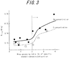
- a specific element-concentrated portion is defined as a portion exhibiting intensity at least 5 ⁇ higher than the average of background intensity (" ⁇ " represents the standard deviation of the background intensity) in analysis of a steel sheet surface and presence ratio of the specific element-concentrated portion in the steel sheet surface is evaluated by an area-occupying ratio per 10000 ⁇ m 2 of an observation field in the present investigation.
- the results are plotted as a relationship between iron loss and the aforementioned area-occupying ratio of Se/S-concentrated portions in FIG. 3 . It has been discovered that iron loss significantly increases when the area-occupying ratio of Se/S-concentrated portions is 2% or higher, as shown in FIG. 3 . Further, the inventors of the present invention made an investigation for Al-concentrated portions, similarly to the experiment described above and found out that iron loss significantly increases when the area-occupying ratio of Al-concentrated portions is 5% or higher.
- the inventors of the present invention keenly studied factors that influence on increase in iron loss and revealed that irradiation of plasma flame, which locally imparts a steel sheet with strains to cause magnetic domain refinement, may significantly damages forsterite film in a case where the forsterite film has a specific structure, i.e. the forsterite film includes specific element-concentrated portions by area-occupying ration thereof equal to or higher than 2%.
- the inventors of the present invention therefore investigated a method for imparting base steel with sufficient thermal strain, while avoiding heating forsterite film, in connection with the aforementioned materials and discovered that magnetic domain refinement by electron beam irradiation, in particular electron beam irradiation with narrowed irradiation beam diameter and higher scanning rate and acceleration voltage, is very suitable for the method, thereby completing the present invention.
- primary features of the present invention are defined in the claims.
- the present invention provides a grain oriented electrical steel sheet, comprising: forsterite film on a surface of base steel sheet and an aluminum-concentrated portion in at least one of the forsterite film and an interface between the forsterite film and the base steel sheet by presence ratio(s) expressed as area-occupying ratio(s) of the Al-concentrated portion, of at least 5% per 10000 ⁇ m 2 of the surface of the base steel sheet, which has been subjected to magnetic domain refinement treatment by means of electron beam irradiation under the conditions specified below.
- the present invention provides a method for manufacturing a grain oriented electrical steel sheet, comprising the steps of: preparing a prefinished grain oriented electrical steel sheet having forsterite film on a surface of base steel sheet and an aluminum-concentrated portion in at least one of the forsterite film and an interface between the forsterite film and the base steel sheet by presence ratio(s) expressed as area-occupying ratio(s) of the Al-concentrated portion, of at least 5% per 10000 ⁇ m 2 of the surface of the base steel sheet; and irradiating the prefinished grain oriented electrical steel sheet with electron beam to subject the steel sheet to magnetic domain refinement.
- the prefinished grain oriented electrical steel sheet is irradiated with electron beam under conditions including: 0.05 mm ⁇ electron beam diameter ⁇ 0.5 mm; scanning rate of electron beam ⁇ 1.0 m/second; and acceleration voltage ⁇ 30 kV.
- the present invention by subjecting a grain oriented electrical steel sheet having a specific element-concentrated portion in at least one of forsterite film on a surface of base steel sheet and an interface between the forsterite film and the base steel sheet to magnetic domain refinement through irradiation of electron beam, it is possible to prevent a magnetic domain refinement effect from being reduced by damage to forsterite film, whereby the magnetic domain refinement effect is maximally caused to achieve very low iron loss.
- a grain oriented electrical steel sheet having a specific element-concentrated portion in at least one of forsterite film and an interface between the forsterite film and base steel sheet is subjected to magnetic domain refinement through irradiation of electron beam.
- the outermost coatings (films), i.e. insulating coating and forsterite film, of a steel sheet are most susceptible to heat when the steel sheet is irradiated with laser because laser increases temperature of a portion irradiated therewith.
- insulating coating and forsterite film, of a steel sheet are most susceptible to heat when the steel sheet is irradiated with plasma flame because the steel sheet is then directly heated by flame at temperature equal to or higher than 10000 °C generated by plasma.
- These methods i.e. laser and plasma flame, essentially involve in magnetic domain refinement of a steel sheet imparting a steel sheet with thermal strain by transferring heat from a surface toward the inner portion of the steel sheet. Accordingly, the outermost coatings of a steel sheet must be significantly heated to reliably introduce thermal strain necessitated for causing a sufficient iron loss-reducing effect to the inner portion of the steel sheet, which heating gravely affects the outermost coatings.
- irradiation of electron beam generates heat through injection of electrons into the inner portion of a steel sheet. Electrons injected into a steel sheet, although they thermally affect the outermost coatings to some extent, can rather directly cause a thermal impact on base steel sheet because electrons readily pass through the coatings and a surface of the base steel sheet.
- irradiation of electron beam significantly differs from irradiation of laser or plasma flame in that the former is capable of causing a thermal impact directly on base steel sheet with suppressing a thermal impact on the outermost coatings. It is therefore possible to cause a significant thermal impact on a steel sheet, with suppressing a thermal impact on forsterite film thereof, by utilizing the unique characteristics of electron beam described above.
- a thermal impact on the forsterite film can be well suppressed by the method of the present invention.
- the inventors of the present invention analyzed iron loss after magnetic domain refinement in an experiment including: preparing a grain oriented electrical steel sheet having 0.23 mm thickness and a Se/S-concentrated portion; and linearly irradiating the steel sheet with electron beam (beam diameter: 0.2 mm, scanning rate: around 3 m/second, acceleration volatage: 30 kV) in a direction orthogonal to the rolling direction of the steel sheet with irradiation interval of 5 mm to impart the steel sheet with thermal strain to cause magnetic domain refinement thereto.
- the result of the experiment is shown in FIG. 4 as relationships between iron loss and respective area-occupying ratios of Se-concentrated portions and S-concentrated portions. It is understood from FIG.
- Area-occupying ratio of Se/S-concentrated portions per 10000 ⁇ m 2 of surface of a base steel sheet is preferably suppressed to 50% or less because forsterite film imparts the steel sheet with tension unevenly when the ratio exceeds 50%.
- Content of Se/S in steel slab need be 0.03 mass % or less when Se or S is used as inhibitor, for example, in order to curb the area-occupying ratio of Se/S-concentrated portions to 50% or less.
- the inventors of the present invention analyzed various types of grain oriented electrical steel sheets by an EPMA to detect specific element-concentrated portions thereof and identified Al as an element which forms a specific element-concentrated portion.
- Selenium and sulfur tend to exist in configurations where these elements very complicatedly interact with forsterite film, thereby significantly affecting surrounding forsterite film when Se/S-concentrated portions expand due to heat.
- aluminum tends to exist at an interface between base steel and forsterite film in a manner of causing a relatively little impact on forsterite film, thereby affecting forsterite film much less than Se and S.
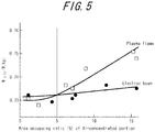
- the inventors of the present invention carried out another experiment for analyzing iron loss after magnetic domain refinement in a grain oriented electrical steel sheet having 0.23 mm thickness and an Al -concentrated portion, in the same manner as in the experiment in connection with Se-concentrated portions and S-concentrated portions.
- the results of the experiment are shown in FIG. 5 . It has been confirmed that iron loss properties of the steel sheet do not deteriorate when area-occupying rate of Al-concentrated area is around 2% but deteriorate when the area-occupying rate is equal to or higher than 5% in a case where magnetic domain refinement is achieved by imparting the steel sheet with thermal strain by plasma flame, as shown in FIG. 5 . It has also been confirmed that deterioration of iron loss properties can be suppressed even when area-occupying rate of Al-concentrated area is equal to or higher than 5% by carrying out magnetic domain refinement by electron beam (see FIG. 5 ).
- Area-occupying ratio of Al-concentrated portions per 10000 ⁇ m 2 of surface of a base steel sheet is preferably suppressed to 50% or less because forsterite film imparts the steel sheet with tension unevenly when the ratio exceeds 50%.
- Content of Al in steel need be 0.065 mass % or less when Al is used as inhibitor in order to curb the area-occupying ratio of Al-concentrated portions to 50% or less.
- the larger irradiation area and/or the longer irradiation time causes the greater thermal impact on forsterite film.
- low acceleration voltage allows electron beam injected into a steel sheet to stay in the vicinity of a surface layer of the steel sheet, thereby possibly intensifying an impact on forsterite film.
- the inventors of the present invention investigated the optimum conditions for allowing electron beam to pass through forsterite film and imparting base steel sheet itself with thermal strain.
- the inventors of the present invention carried out an experiment including irradiating a grain oriented electrical steel sheet having thickness: 0.23 mm and area-occupying ratio of Se-concentrated portions: 3 ⁇ 0.5% with electron beam to impart the steel sheet with thermal strain to carry out magnetic domain refinement in the steel sheet and then measuring iron loss of the steel sheet.
- Electron beam diameter was set to be 0.1 mm, 0.3 mm, 0.5 mm, 0.7 mm, 0.9 mm and 1.0 mm, respectively, to change irradiation area.
- “Diameter” literally represents a diameter, i.e. distance across a beam cross section in the present invention unless mentioned otherwise.
- irradiation direction, an irradiation interval, and the like generally suitable for thermal strain-imparting type magnetic domain refinement when a steel sheet is irradiated with electron beam.
- irradiation of electron beam is effectively carried out by dot-like or linear irradiation using electric current in the range of 0.005 mA to 10 mA in a direction intersecting the rolling direction (preferably a direction inclined with respect to the rolling direction by 60° to 90°) with irradiation interval in the range of 3 mm to 15 mm in the rolling direction.
- a grain oriented electrical steel sheet according to the present invention may be any of conventionally known grain oriented electrical steel sheets.
- Examples of the conventionally known grain oriented electrical steel sheets include an electrical steel material containing Si by 2.0 mass % to 8.0 mass %.
- Silicon is an element which effectively increases electrical resistance of steel to improve iron loss properties thereof. Silicon content in steel equal to or higher than 2.0 mass % ensures a particularly good effect of reducing iron loss. On the other hand, Si content in steel equal to or lower than 8.0 mass % ensures particularly good formability and magnetic flux density of steel. Accordingly, Si content in steel is preferably in the range of 2.0 mass % to 8.0 mass %.
- Magnetic flux density Bs as an index of accumulation of crystal orientations is therefore preferably at least 1.90T.
- chemical composition of the steel material for the steel sheet may contain the following components as starting components.
- Carbon is added to improve microstructure of a hot rolled steel sheet.
- Carbon content in steel is preferably 0.08 mass % or less because carbon content exceeding 0.08 mass % increases burden of reducing carbon content during the manufacturing process to 50 mass ppm or less at which magnetic aging is reliably prevented.
- the lower limit of carbon content in steel need not be particularly set because secondary recrystallization is possible in a material not containing carbon.
- Manganese is an element which advantageously achieves good hot-formability of steel. Manganese content in steel less than 0.005 mass % cannot cause the good effect of Mn addition sufficiently. Manganese content in steel equal to or lower than 1.0 mass % ensures particularly good magnetic flux density of a product steel sheet. Accordingly, Mn content in steel is preferably in the range of 0.005 mass % to 1.0 mass %.
- chemical composition of the steel material for the grain oriented electrical steel sheet of the present invention may contain, for example, appropriate amounts of Al and N in a case where an AlN-based inhibitor is utilized or appropriate amounts of Mn and Se and/or S in a case where MnS and/or MnSe-based inhibitor is utilized. Both AlN-based inhibitor and MnS ⁇ MnSe-based inhibitor may be used in combination, of course.
- contents of Al, N, S and Se are preferably Al: 0.01 mass % to 0.065 mass %, N: 0.005 mass % to 0.012 mass %, S: 0.005 mass % to 0.03 mass %, and Se: 0.005 mass % to 0.03 mass %, respectively.
- the steel material for the grain oriented electrical steel sheet of the present invention may contain, for example, following elements as magnetic properties improving components in addition to the basic components described above. At least one element selected from Ni: 0.03 mass % to 1.50 mass %. Sn: 0.01 mass % to 1.50 mass %, Sb: 0.005 mass % to 1.50 mass %, Cu: 0.03 mass % to 3.0 mass %, P: 0.03 mass % to 0.50 mass %, Mo: 0.005 mass % to 0.10 mass %, Nb: 0.0005 mass % to 0.0100 mass %, and Cr: 0.03 mass % to 1.50 mass % Nickel is a useful element in terms of further improving microstructure of a hot rolled steel sheet and thus magnetic properties of a resulting steel sheet.
- Nickel content in steel less than 0.03 mass % cannot cause this magnetic properties-improving effect by Ni sufficiently.
- Nickel content in steel equal to or lower than 1.5 mass % ensures stability in secondary recrystallization to improve magnetic properties of a resulting steel sheet. Accordingly, Ni content in steel is preferably in the range of 0.03 mass % to 1.5 mass %.
- the steel material for the grain oriented electrical steel sheet of the present invention contains at least one of Sn, Sb, Cu, P, Mo, Nb and Cr within the respective ranges thereof specified above.
- the balance other than the aforementioned components of the steel material for the grain oriented electrical steel sheet of the present invention is preferably Fe and incidental impurities incidentally mixed thereinto during the manufacturing process.
- a steel slab having the aforementioned chemical composition is subjected to the conventional processes for manufacturing a grain oriented electrical steel sheet including annealing for secondary recrystallization and formation of tension insulating coating thereon, to be finished as a grain oriented electrical steel sheet.
- a grain oriented electrical steel sheet is manufactured by: subjecting the steel slab to heating and hot rolling to obtain a hot rolled steel sheet; subjecting the hot rolled steel sheet to either a single cold rolling operation or at least two cold rolling operations with intermediate annealing therebetween to obtain a cold rolled steel sheet having the final sheet thickness; and subjecting the cold rolled steel sheet to decarburization, annealing for primary recrystallization, coating of annealing separator mainly composed of magnesia, and the final annealing including secondary recystallization process and purification process in this order.
- Annealing separator mainly composed of magnesia means in the present invention that the annealing separator may contain known annealing separator components and/or physical/chemical property-improving components other than magnesia unless presence thereof inhibits formation of forsterite film relevant to the main object of the present invention.
- magnesia as annealing separator, magnesia having activity distribution with the expected value ⁇ (A) in the range of 3.4 to 3.7 and the standard deviation ⁇ (A) in the range of 2.0 to 2.6 may be preferentially used in the present invention.
- the expected value ⁇ (A) and the standard deviation ⁇ (A) can be calculated as follows. First, random variable (A) is defined as below.
- the method disclosed in paragraphs [0017] to [0023] of Patent Literature 3 described above can be employed as a specific method for determining activity distribution of magnesia. Further, preferable conditions and adjusting methods regarding activity distribution and annealing separator are preferably selected based on the descriptions in paragraphs [0041] to [0045] of Patent Literature 3.
- the annealing separator preferably contains Ti compound by 0.5-6 parts by mass (when converted into Ti content) and at least one of Ca, Sr, Ba and Mg compounds by 0.2-3.0 parts by mass (when converted into content of the relevant metal) with respect to 100 parts by mass of magnesia.
- the annealing separator may further contain additives for improving various physical/chemical properties thereof.
- Specific elements such as Se, S and Al may be concentrated in forsterite film when magnesia as described above is used as annealing separator. This phenomenon occurs presumably because there arises a state where formation of forsterite film has been only partially completed at the temperature at which inhibitor substance is decomposed and specific elements derived therefrom migrate to a steel sheet surface to be concentrated there, whereby concentration of the specific elements preferentially proceeds at portions where forsterite film has not been formed yet.
- the present invention is effectively applicable to not only the technique of Patent Literature 3 but also every case where improvement of a grain oriented electrical steel sheet and/or a method for the grain oriented electrical steel sheet causes Se, S and/or Al to be concentrated in forsterite film and/or an interface between the coating and base steel sheet.
- improvement of a grain oriented electrical steel sheet and/or a method for the grain oriented electrical steel sheet causes Se, S and/or Al to be concentrated in forsterite film and/or an interface between the coating and base steel sheet.
- forsterite film formation does not proceed uniformly but occurs concurrently with concentration of inhibitor-derived components at a steel sheet surface due to controllable change in atmosphere during final annealing, whereby the resulting forsterite film includes specific element-concentrated portions.
- the present invention is effectively applicable to such a case as described above.
- a steel sheet thus subjected to final annealing according to the method of the present invention described above is then provided, by coating, with tension insulating coating composed of, e.g. colloidal silica and a phosphate salt (magnesium phosphate, aluminum phosphate or the like) and baked.
- tension insulating coating composed of, e.g. colloidal silica and a phosphate salt (magnesium phosphate, aluminum phosphate or the like) and baked.
- the steel sheet is irradiated, for example, in a direction inclined with respect to the rolling direction of the steel sheet by 60° to 90° (preferably 90° or in a widthwise direction) with electron beam of which beam diameter at an irradiation position has been converged to the range of 0.05 mm to 1 mm so that thermal strain is introduced in a linear or dot-like manner to the steel sheet.
- the upper and lower limits of electron beam diameter are 0.05 mm and 1.0 mm, respectively, and the beam diameter is preferably 0.5 mm or less to ensure good physical properties.
- the beam diameter is to be at least 0.05 mm because too small beam diameter lessens an effect of dividing magnetic domains for magnetic domain refinement.
- the beam diameter is to be equal to or smaller than 1.0 mm because too large beam diameter increases an area where strain is introduced and deteriorates hysteresis loss properties in particular.
- Electron beam diameter equal to or smaller than 0.5 mm is preferable because then hysteresis loss properties are prevented from deteriorating and an iron loss-improving effect can be maximally obtained.
- scanning rate an adverse effect on forsterite film can be avoided by setting scanning rate to be at least 1.0 m/second. The upper limit of scanning rate does not particularly need to be specified.
- Scanning rate is preferably 1000 m/second or less in view of required facilities because excessively high scanning rate necessitates high energy (electric current, voltage) in order to maintain sufficiently high output per unit length of a steel sheet.
- acceleration voltage acceleration voltage of 30 kV or higher allows electron beam to pass through forsterite film to directly impart a steel sheet with thermal strain.
- the upper limit of acceleration voltage does not particularly need to be specified.
- Acceleration voltage is preferably equal to or lower than 300 kV because irradiation with too high acceleration voltage causes strain to widely spread in a steel sheet in the depth direction thereof and makes it difficult to control the strain depth within a preferred range.
- Output of electron beam is to be in the range of 10 W to 2000 W and irradiation conditions are preferably adjusted such that irradiation is carried out linearly with output of electron beam per unit length in the range of around 1 J/m to 50 J/m and irradiation interval in the range of around 1 mm to 20 mm.
- Depth of strain imparted to a steel sheet through irradiation of electron beam in the present invention is preferably in the range of 5 ⁇ m to 30 ⁇ m measured from a steel sheet surface. Needless to say, the foregoing descriptions do not prevent electron beam irradiation conditions other than described above from being applied to the present invention.
- a grain oriented electrical steel sheet having the final sheet thickness of 0.23 mm was prepared from a steel slab containing Si by 3 mass % by manufacturing processes using at least one of MnSe, MnS and A1N as inhibitor elements.
- the manufacturing processes of the grain oriented electrical steel sheet included: obtaining a cold rolled steel sheet having the final sheet thickness by rolling; and subjecting the cold rolled steel sheet to decarburization, annealing for primary recrystallization, coating of annealing separator mainly composed of MgO having activity distribution with the expected value ⁇ (A) in the range of 3.4 to 3.7 and the standard deviation ⁇ (A) in the range of 2.0 to 2.6, and final annealing including secondary recrystallization process and purification process at the maximum temperature of 1200°C with 10-hour soaking time in this order.
- the electrical steel sheet having forsterite film thus obtained was provided, by coating, with insulating coating made of 60% colloidal silica and aluminum phosphate such that coating weight was 5 g/mm 2 per one
- Test specimens were cut out of the center portion in the coil widthwise direction of the grain oriented electrical steel sheet thus prepared. B 8 value of each of these test specimens was measured. The test specimens exhibiting B 8 value of 1.92T ⁇ 0.001T were selected. Area-occupying ratios of respective specific element-concentrated portions were determined by using an EPMA for each of the test specimens thus selected.
- each of the test specimens thus selected was subjected to magnetic domain refinement in a direction orthogonal to the rolling direction by using two different magnetic domain refinement techniques, i.e. plasma flame and electron beam, and then iron loss after magnetic domain refinement of the test specimen was measured.
- Irradiation of electron beam was carried out at two levels: 0.3 mm and 1 mm for irradiation beam diameter, two levels: 2 m/second and 0.5 m/second for scanning rate, and two levels: 20 kV and 100 kV for acceleration voltage.
- Table 1 It is understood from Table 1 that satisfactory iron loss properties were successfully obtained without deterioration thereof under the electron beam irradiation conditions (i.e. Example-type A and Example-type B). It is also understood from Table 1 that better iron loss properties were successfully obtained by electron beam irradiation within the condition ranges of Example-type A than in Example-type B.
- Example 2 6.5% ⁇ 1% ⁇ 1% Electron beam 0.3mm 2m/second 100kV 0.728
- Example-type A 3 1.8% ⁇ 1% ⁇ 1%
- Electron beam 0.3mm 0.5m/second 100kV 0.730 Reference Example 4 6.5% ⁇ 1% ⁇ 1% Electron beam 1.0mm 0.5m/second 20kV 0.734
- Example-type B 5 MnS ⁇ 1% 1.8% ⁇ 1%
- Electron beam 0.3mm 2m/second 100kV 0.725 Reference Example 6 ⁇ 1% 4.5% ⁇ 1%
- Electron beam 0.3mm 2m/second 100kV 0.725 Example-type A 7 ⁇ 1% 1.8% ⁇ 1% Plasma flame - - - 0.727 Reference Example 8 ⁇ 1% 4.5% ⁇ 1% Plasma flame - - - 0.748 Comp.
- Example 9 A1N ⁇ 1% ⁇ 1% 3.0% Electron beam 0.3mm 2m/second 20kV 0.731 Reference Example 10 ⁇ 1% ⁇ 1% 7.0% Electron beam 0.3mm 2m/second 20kV 0.735 Example-type B 11 ⁇ 1% ⁇ 1% 8.0% Electron beam 0.3mm 2m/second 100kV 0.729 Example-type A 12 ⁇ 1% ⁇ 1% 7.0% Plasma flame - - - 0.742 Comp.
- examples 1-8 do not form part of the invention
- a steel slab containing Si by 3 mass % was manufactured by using both MnSe and AlN as inhibitor elements.
- a grain oriented electrical steel sheet having the final sheet thickness of 0.27 mm was prepared from the steel slab.
- the manufacturing processes of the grain oriented electrical steel sheet included: obtaining a cold rolled steel sheet having the final sheet thickness by rolling; and subjecting the cold rolled steel sheet to decarburization, annealing for primary recrystallization, coating, on a steel sheet surface, of annealing separator composed of MgO having activity distribution as specified in Patent Literature 3 as the main component and Sr compound and Ti compound as an auxiliary component, and coiling with interlayer interval of 15 ⁇ m in this order to obtain a coiled steel sheet.
- the coiled steel sheet was subjected to final annealing (the maximum temperature: 1200°C, soaking time: 10 hours).
- the electrical steel sheet having forsterite film thus obtained was provided, by coating, with insulating coating made of 60% colloidal silica and aluminum phosphate and baked at 800 °C.
- Test specimens were cut out of the center portion in the coil widthwise direction of the grain oriented electrical steel sheet thus prepared. B 8 value of each of these test specimens was measured. The test specimens exhibiting B 8 value of 1.91T ⁇ 0.001T were selected. Area-occupying ratio of Se-concentrated portions was determined by using an EPMA for each of the test specimens thus selected. Each of the test specimens exhibited area-occupying ratio of Se-concentrated portions of at least 2%. Next, one of the test specimens thus obtained was irradiated with plasma flame in a direction orthogonal to the rolling direction for magnetic domain refinement (Comparative Example). Other test specimens were each irradiated with electron beam for magnetic domain refinement. Irradiation interval was unanimously 5 mm.
- Iron loss after magnetic domain refinement was measured for each of the test specimens. Irradiation conditions of electron beam, measured physical properties, and relevant parameters are summarized in Table 2. It is understood from Table 2 that satisfactory iron loss properties were successfully obtained by electron beam irradiation (Example-type C and Example-type D). It is also understood from Table 2 that better iron loss properties were successfully obtained by more adequate electron beam irradiation (Example-type D) than otherwise (Example-type C).
Description
- The present invention relates to a grain oriented electrical steel sheet having excellent iron loss properties, for use in an iron core material of a transformer or the like.
- A grain oriented electrical steel sheet is mainly utilized as an iron core of a transformer and required to exhibit excellent magnetization characteristics, e.g. low iron loss in particular. In this regard, it is important to highly accord secondary recrystallized grains of a steel sheet with (110)[001] orientation, i.e. what is called "Goss orientation", and reduce impurities in a product steel sheet. However, there are limits on controlling crystal grain orientations and reducing impurities in view of production cost. Accordingly, there have been developed techniques for iron loss reduction, which is to apply non-uniformity (strain) to a surface of a steel sheet physically to subdivide magnetic domain width, i.e. magnetic domain refinement techniques. For example,
Patent Literature 1 proposes a technique of irradiating a steel sheet after final annealing with laser to introduce high-dislocation density regions into a surface layer of the steel sheet, thereby narrowing magnetic domain widths and reducing iron loss of the steel sheet. Further,Patent Literature 2 proposes for actual implementation a technique of controlling magnetic domain widths by irradiating a steel sheet with plasma flame.Patent Literature 4 discloses the use of electron beam treatment for magnetic domain refinement. - A manufacturing process of a grain oriented electrical steel sheet generally involves secondary recrystallization of steel facilitated by use of precipitates such as MnS, MnSe, AlN and the like referred to as "inhibitors". A grain oriented electrical steel sheet thus manufactured by using inhibitors has a primer coating referred to as "forsterite" (coating mainly composed of Mg2SiO4) on a surface thereof and an insulating tension coating is often formed on this forsterite film. An insulating tension coating formed on forsterite film is useful in terms of reducing iron loss of the steel sheet, as well as causing a good effect on the base steel subjected to magnetic domain refinement described above.
-
Patent Literature 3 discloses in connection with characteristics of forsterite film that characteristics of forsterite film improve and thus a grain oriented electrical steel sheet having excellent film properties can be manufactured by using, as annealing separator during final annealing, magnesia of which expected value in distribution of activity has been controllably set to be within a range of specific standard deviation. -
- PTL 1:
JP-B 57-002252 - PTL 2:
JP-A 62-096617 - PTL 3:
JP-A 2004-353054 - PTL 4:
EP 0 331 497 A1 - The inventors of the present invention, however, have noticed the following problems in connection with the production method according to
Patent Literature 3. Specifically, when magnesia having the aforementioned specific activity distribution is used as annealing separator, i.e. as a material of forsterite film, a resulting formation rate of forsterite film differs from the conventionally observed rate, whereby concentration of the inhibitor elements (S, Se, Al and the like) at a surface of a steel sheet may occur concurrently with formation of forsterite film, depending on components of the steel sheet and/or annealing conditions for secondary recrystallization of steel. -
Patent Literature 3 discloses that magnesia generally includes low-activity component, intermediate-activity component, and high-activity component and that good magnetic properties and formation of satisfactorily hard film of a steel sheet can be achieved in a compatible manner by adjusting chemical composition, including these three types of components, of magnesia such that magnesia collectively meets adequate activity distribution µ (A) and adequate standard deviation σ(A), respectively.Patent Literature 3 also discloses that decomposition of inhibitors is suppressed when the annealing separator contains alkali earth metal ions such as Ca, Sr, Br or the like. There is a known phenomenon that an inhibitor component, after decomposition of inhibitor substance in steel, tends to be concentrated at a surface of a steel sheet. Timing of forsterite film formation differs depending on degree of activity of magnesia. As a result, in a case of using an annealing separator of which activity distribution of magnesia has been adjusted in accordance with the conditions specified inPatent Literature 3 and which contains alkali earth metal ions, temperature at which the inhibitor substance is decomposed rises up and formation of forsterite film unevenly proceeds predominantly at sites where low-activity magnesia component exists, whereby inhibitor components derived from the inhibitor substance are concentrated at a portion where forsterite film has not been formed yet. Consequently, specific elements may exist in a concentrated manner at an interface between forsterite film and base steel sheet and/or in forsterite film in some applications, as shown in secondary electron images in the vicinity of an interface between base steel sheet and forsterite film ofFIG. 1 , which images are observed at a cross section in a direction orthogonal to the rolling direction of a steel sheet product having insulating coating on forsterite film. - Further,
Patent Literature 3 discloses that low-activity component, intermediate-activity component, and high-activity component of magnesia contribute to concentrations at a steel sheet surface of alkali earth metal, Mg, and Ti, respectively. Judging from these facts, there is a possibility that use of magnesia having such activity distribution µ (A) as disclosed inPatent Literature 3 facilitates concentration of inhibitor components derived from inhibitor substance at a steel sheet surface when magnesia having the activity distribution µ (A) is used, although relationship between such specific magnesia as described above and the inhibitor components has not been clearly revealed. - In a case where a steel sheet including inhibitor components in such a concentrated manner as described above is subjected to magnetic domain refinement utilizing thermal strains caused by plasma flame or laser, forsterite film may be damaged and/or adhesion properties of the film may deteriorate because coefficients of thermal expansion are different between a portion where specific elements have been coagulated and concentrated and portions surrounding the portion of the forsterite film. Further, tension imparted to the steel sheet by insulating coating formed on forsterite film is made non-uniform, which may make it impossible to obtain a sufficient iron-loss reducing effect.
- In view of the facts described above, an object of the present invention is to provide a grain oriented electrical steel sheet successfully exhibiting low iron loss by carrying out magnetic domain refinement free of the iron-loss deteriorating factors described above.
- The inventors of the present invention first investigated a method for quantitatively analyzing a specific element-concentrated portion formed in a steel sheet when magnesia having the specific activity distribution disclosed in
Patent Literature 3 is used. As a result, they succeeded in quantitatively analyzing a specific element-concentrated portion by scanning a surface of the steel sheet by using an EPMA (Electron Probe Micro Analyzer) at acceleration voltage: 10 kV to 20 kV. Specifically,FIG. 2 shows a two-dimensional mapping image of element Se, obtained by observing an observation field (100 µm × 100 µm) at measurement pitch: 0.5 µm by using an EPMA. Each dot-like portion observed inFIG. 2 represents a Se-concentrated portion. A specific element-concentrated portion may spread in a solid-solute state throughout forsterite film, depending on types of the element. When a cross-sectional observation was carried out, by regarding a portion exhibiting intensity at least 5σ higher than the average of background intensity ("σ" represents the standard deviation of the background intensity) as a specific element-concentrated portion, presence of specific element-concentrated portions as shown inFIG. 1 was confirmed. Accordingly, a specific element-concentrated portion is defined as a portion exhibiting intensity at least 5σ higher than the average of background intensity ("σ" represents the standard deviation of the background intensity) in analysis of a steel sheet surface and presence ratio of the specific element-concentrated portion in the steel sheet surface is evaluated by an area-occupying ratio per 10000 µm2 of an observation field in the present investigation. - Next, an investigation was made to determine a threshold value of presence ratio of specific element-concentrated portion(s), provided that presence ratio exceeding which threshold value lessens an iron-loss reducing effect by magnetic domain refinement in
Experiment 1 in connection with magnetic domain refinement involving: preparing a grain oriented electrical steel sheet having 0.23 mm thickness and Se/S-concentrated portions; and linearly irradiating the grain oriented electrical steel sheet with plasma flame (nozzle diameter: 0.15 mm, gas used for generation of plasma: Ar, voltage: 30V, electric current: 7A, and scanning rate of nozzle: 200 mm/second) in a direction orthogonal to the rolling direction of the steel sheet with irradiation interval: 5 mm to impart the steel sheet with thermal strain. The results are plotted as a relationship between iron loss and the aforementioned area-occupying ratio of Se/S-concentrated portions inFIG. 3 . It has been discovered that iron loss significantly increases when the area-occupying ratio of Se/S-concentrated portions is 2% or higher, as shown inFIG. 3 . Further, the inventors of the present invention made an investigation for Al-concentrated portions, similarly to the experiment described above and found out that iron loss significantly increases when the area-occupying ratio of Al-concentrated portions is 5% or higher. - Further, the inventors of the present invention keenly studied factors that influence on increase in iron loss and revealed that irradiation of plasma flame, which locally imparts a steel sheet with strains to cause magnetic domain refinement, may significantly damages forsterite film in a case where the forsterite film has a specific structure, i.e. the forsterite film includes specific element-concentrated portions by area-occupying ration thereof equal to or higher than 2%. The inventors of the present invention therefore investigated a method for imparting base steel with sufficient thermal strain, while avoiding heating forsterite film, in connection with the aforementioned materials and discovered that magnetic domain refinement by electron beam irradiation, in particular electron beam irradiation with narrowed irradiation beam diameter and higher scanning rate and acceleration voltage, is very suitable for the method, thereby completing the present invention.
Specifically, primary features of the present invention are defined in the claims. - In summary, the present invention provides a grain oriented electrical steel sheet, comprising: forsterite film on a surface of base steel sheet and an aluminum-concentrated portion in at least one of the forsterite film and an interface between the forsterite film and the base steel sheet by presence ratio(s) expressed as area-occupying ratio(s) of the Al-concentrated portion, of at least 5% per 10000 µm2 of the surface of the base steel sheet, which has been subjected to magnetic domain refinement treatment by means of electron beam irradiation under the conditions specified below.
- Further, the present invention provides a method for manufacturing a grain oriented electrical steel sheet, comprising the steps of: preparing a prefinished grain oriented electrical steel sheet having forsterite film on a surface of base steel sheet and an aluminum-concentrated portion in at least one of the forsterite film and an interface between the forsterite film and the base steel sheet by presence ratio(s) expressed as area-occupying ratio(s) of the Al-concentrated portion, of at least 5% per 10000 µm2 of the surface of the base steel sheet; and irradiating the prefinished grain oriented electrical steel sheet with electron beam to subject the steel sheet to magnetic domain refinement. The prefinished grain oriented electrical steel sheet is irradiated with electron beam under conditions including: 0.05 mm ≤ electron beam diameter ≤ 0.5 mm; scanning rate of electron beam ≥ 1.0 m/second; and acceleration voltage ≥ 30 kV.
- According to the present invention, by subjecting a grain oriented electrical steel sheet having a specific element-concentrated portion in at least one of forsterite film on a surface of base steel sheet and an interface between the forsterite film and the base steel sheet to magnetic domain refinement through irradiation of electron beam, it is possible to prevent a magnetic domain refinement effect from being reduced by damage to forsterite film, whereby the magnetic domain refinement effect is maximally caused to achieve very low iron loss.
-
-
FIG. 1 shows secondary electron images observed at a cross section in a direction orthogonal to the rolling direction of a steel sheet having a Se-concentrated portion in forsterite film. -
FIG. 2 is a two-dimensional mapping image showing Se-concentrated portions analyzed by an EPMA. -
FIG. 3 is a graph showing relationships between iron loss after plasma flame irradiation treatment and respective area-occupying ratios of Se-concentrated portions and S-concentrated portions. -
FIG. 4 is a graph showing relationships between iron loss after electron beam irradiation treatment and respective area-occupying ratios of Se-concentrated portions and S-concentrated portions. -
FIG. 5 is a graph showing relationship between iron loss and area-occupying ratio of Al - concentrated portions. - In the present invention, it is critically important that a grain oriented electrical steel sheet having a specific element-concentrated portion in at least one of forsterite film and an interface between the forsterite film and base steel sheet is subjected to magnetic domain refinement through irradiation of electron beam. Specifically, the outermost coatings (films), i.e. insulating coating and forsterite film, of a steel sheet are most susceptible to heat when the steel sheet is irradiated with laser because laser increases temperature of a portion irradiated therewith. Similarly, the outermost coatings, i.e. insulating coating and forsterite film, of a steel sheet are most susceptible to heat when the steel sheet is irradiated with plasma flame because the steel sheet is then directly heated by flame at temperature equal to or higher than 10000 °C generated by plasma. These methods, i.e. laser and plasma flame, essentially involve in magnetic domain refinement of a steel sheet imparting a steel sheet with thermal strain by transferring heat from a surface toward the inner portion of the steel sheet. Accordingly, the outermost coatings of a steel sheet must be significantly heated to reliably introduce thermal strain necessitated for causing a sufficient iron loss-reducing effect to the inner portion of the steel sheet, which heating gravely affects the outermost coatings.
- In contrast, irradiation of electron beam generates heat through injection of electrons into the inner portion of a steel sheet. Electrons injected into a steel sheet, although they thermally affect the outermost coatings to some extent, can rather directly cause a thermal impact on base steel sheet because electrons readily pass through the coatings and a surface of the base steel sheet. As a result, irradiation of electron beam significantly differs from irradiation of laser or plasma flame in that the former is capable of causing a thermal impact directly on base steel sheet with suppressing a thermal impact on the outermost coatings.
It is therefore possible to cause a significant thermal impact on a steel sheet, with suppressing a thermal impact on forsterite film thereof, by utilizing the unique characteristics of electron beam described above. Specifically, in a case where the outermost coatings of a steel sheet are susceptible to heat as in the present invention where a steel sheet has in at least one of forsterite film and an interface between the forsterite film and base steel sheet a specific element-concentrated portion having thermal expansion ratio different from that of forsterite film, a thermal impact on the forsterite film can be well suppressed by the method of the present invention. - The inventors of the present invention analyzed iron loss after magnetic domain refinement in an experiment including: preparing a grain oriented electrical steel sheet having 0.23 mm thickness and a Se/S-concentrated portion; and linearly irradiating the steel sheet with electron beam (beam diameter: 0.2 mm, scanning rate: around 3 m/second, acceleration volatage: 30 kV) in a direction orthogonal to the rolling direction of the steel sheet with irradiation interval of 5 mm to impart the steel sheet with thermal strain to cause magnetic domain refinement thereto. The result of the experiment is shown in
FIG. 4 as relationships between iron loss and respective area-occupying ratios of Se-concentrated portions and S-concentrated portions. It is understood fromFIG. 4 that satisfactorily low iron loss values were obtained even when the area-occupying ratios of Se-concentrated portions and S-concentrated portions exceeded 2% per 10000 µm2 of the surface of the base steel sheet, respectively. In other words, it is understood that satisfactorily low iron loss can be maintained even when area-occupying ratio of specific element-concentrated portion(s) exceeds 2% per 10000 µm2 of the surface of the base steel sheet, by replacing plasma flame irradiation with electron beam irradiation in magnetic domain refinement when an experiment is carried out under treatment conditions similar to those of the experiment of which results are shown inFIG. 3 . - Area-occupying ratio of Se/S-concentrated portions per 10000 µm2 of surface of a base steel sheet is preferably suppressed to 50% or less because forsterite film imparts the steel sheet with tension unevenly when the ratio exceeds 50%. Content of Se/S in steel slab need be 0.03 mass % or less when Se or S is used as inhibitor, for example, in order to curb the area-occupying ratio of Se/S-concentrated portions to 50% or less.
- Further, the inventors of the present invention analyzed various types of grain oriented electrical steel sheets by an EPMA to detect specific element-concentrated portions thereof and identified Al as an element which forms a specific element-concentrated portion. Selenium and sulfur tend to exist in configurations where these elements very complicatedly interact with forsterite film, thereby significantly affecting surrounding forsterite film when Se/S-concentrated portions expand due to heat. On the other hand, aluminum tends to exist at an interface between base steel and forsterite film in a manner of causing a relatively little impact on forsterite film, thereby affecting forsterite film much less than Se and S.
The inventors of the present invention carried out another experiment for analyzing iron loss after magnetic domain refinement in a grain oriented electrical steel sheet having 0.23 mm thickness and an Al -concentrated portion, in the same manner as in the experiment in connection with Se-concentrated portions and S-concentrated portions. The results of the experiment are shown inFIG. 5 . It has been confirmed that iron loss properties of the steel sheet do not deteriorate when area-occupying rate of Al-concentrated area is around 2% but deteriorate when the area-occupying rate is equal to or higher than 5% in a case where magnetic domain refinement is achieved by imparting the steel sheet with thermal strain by plasma flame, as shown inFIG. 5 . It has also been confirmed that deterioration of iron loss properties can be suppressed even when area-occupying rate of Al-concentrated area is equal to or higher than 5% by carrying out magnetic domain refinement by electron beam (seeFIG. 5 ). - Area-occupying ratio of Al-concentrated portions per 10000 µm2 of surface of a base steel sheet is preferably suppressed to 50% or less because forsterite film imparts the steel sheet with tension unevenly when the ratio exceeds 50%. Content of Al in steel need be 0.065 mass % or less when Al is used as inhibitor in order to curb the area-occupying ratio of Al-concentrated portions to 50% or less.
- Regarding electron beam used in magnetic domain refinement, it is assumed that the larger irradiation area and/or the longer irradiation time causes the greater thermal impact on forsterite film. Further, low acceleration voltage allows electron beam injected into a steel sheet to stay in the vicinity of a surface layer of the steel sheet, thereby possibly intensifying an impact on forsterite film. In view of this, the inventors of the present invention investigated the optimum conditions for allowing electron beam to pass through forsterite film and imparting base steel sheet itself with thermal strain.
- Specifically, the inventors of the present invention carried out an experiment including irradiating a grain oriented electrical steel sheet having thickness: 0.23 mm and area-occupying ratio of Se-concentrated portions: 3±0.5% with electron beam to impart the steel sheet with thermal strain to carry out magnetic domain refinement in the steel sheet and then measuring iron loss of the steel sheet. Electron beam diameter was set to be 0.1 mm, 0.3 mm, 0.5 mm, 0.7 mm, 0.9 mm and 1.0 mm, respectively, to change irradiation area. "Diameter" literally represents a diameter, i.e. distance across a beam cross section in the present invention unless mentioned otherwise. Scanning rate and acceleration voltage of electron beam were fixed at 2 m/second and 50 kV, respectively, in this connection.
On the other hand, when irradiation time was to be changed, scanning rate was set to be 0.1 m/second, 0.5 m/second, 1.0 m/second, 2.0 m/second and 3.0 m/second, respectively, while electron beam diameter and acceleration voltage were fixed at 0.3 mm and 50 kV as the standard values, respectively. When acceleration voltage was to be changed, acceleration voltage was set to be 10 kV, 20 kV, 30 kV, 50 kV and 100 kV, respectively, while electron beam diameter and scanning rate were fixed at 0.3 mm and 2 m/second as the standard values, respectively. As a result, it has been revealed that electron beam is preferably 0.5 mm or less, scanning rate is preferably at least 1.0 m/second, and acceleration voltage is preferably at least 30 kV in terms of improving iron loss properties. - It is preferable to employ an irradiation direction, an irradiation interval, and the like generally suitable for thermal strain-imparting type magnetic domain refinement when a steel sheet is irradiated with electron beam. Specifically, irradiation of electron beam is effectively carried out by dot-like or linear irradiation using electric current in the range of 0.005 mA to 10 mA in a direction intersecting the rolling direction (preferably a direction inclined with respect to the rolling direction by 60° to 90°) with irradiation interval in the range of 3 mm to 15 mm in the rolling direction.
- A grain oriented electrical steel sheet according to the present invention may be any of conventionally known grain oriented electrical steel sheets. Examples of the conventionally known grain oriented electrical steel sheets include an electrical steel material containing Si by 2.0 mass % to 8.0 mass %.
- Silicon is an element which effectively increases electrical resistance of steel to improve iron loss properties thereof. Silicon content in steel equal to or higher than 2.0 mass % ensures a particularly good effect of reducing iron loss. On the other hand, Si content in steel equal to or lower than 8.0 mass % ensures particularly good formability and magnetic flux density of steel. Accordingly, Si content in steel is preferably in the range of 2.0 mass % to 8.0 mass %.
- The higher degree of accumulation of crystal grains in <100> direction causes the better effect of reducing iron loss through magnetic domain refinement. Magnetic flux density Bs as an index of accumulation of crystal orientations is therefore preferably at least 1.90T.
- In manufacturing the grain oriented electrical steel sheet of the present invention, chemical composition of the steel material for the steel sheet may contain the following components as starting components.
- Carbon is added to improve microstructure of a hot rolled steel sheet. Carbon content in steel is preferably 0.08 mass % or less because carbon content exceeding 0.08 mass % increases burden of reducing carbon content during the manufacturing process to 50 mass ppm or less at which magnetic aging is reliably prevented. The lower limit of carbon content in steel need not be particularly set because secondary recrystallization is possible in a material not containing carbon.
- Manganese is an element which advantageously achieves good hot-formability of steel. Manganese content in steel less than 0.005 mass % cannot cause the good effect of Mn addition sufficiently. Manganese content in steel equal to or lower than 1.0 mass % ensures particularly good magnetic flux density of a product steel sheet. Accordingly, Mn content in steel is preferably in the range of 0.005 mass % to 1.0 mass %.
- When an inhibitor is to be used for facilitating secondary recrystallization, chemical composition of the steel material for the grain oriented electrical steel sheet of the present invention may contain, for example, appropriate amounts of Al and N in a case where an AlN-based inhibitor is utilized or appropriate amounts of Mn and Se and/or S in a case where MnS and/or MnSe-based inhibitor is utilized. Both AlN-based inhibitor and MnS · MnSe-based inhibitor may be used in combination, of course. When inhibitors are used as described above, contents of Al, N, S and Se are preferably Al: 0.01 mass % to 0.065 mass %, N: 0.005 mass % to 0.012 mass %, S: 0.005 mass % to 0.03 mass %, and Se: 0.005 mass % to 0.03 mass %, respectively.
- Further, the steel material for the grain oriented electrical steel sheet of the present invention may contain, for example, following elements as magnetic properties improving components in addition to the basic components described above.
At least one element selected from Ni: 0.03 mass % to 1.50 mass %. Sn: 0.01 mass % to 1.50 mass %, Sb: 0.005 mass % to 1.50 mass %, Cu: 0.03 mass % to 3.0 mass %, P: 0.03 mass % to 0.50 mass %, Mo: 0.005 mass % to 0.10 mass %, Nb: 0.0005 mass % to 0.0100 mass %, and Cr: 0.03 mass % to 1.50 mass %
Nickel is a useful element in terms of further improving microstructure of a hot rolled steel sheet and thus magnetic properties of a resulting steel sheet. Nickel content in steel less than 0.03 mass % cannot cause this magnetic properties-improving effect by Ni sufficiently. Nickel content in steel equal to or lower than 1.5 mass % ensures stability in secondary recrystallization to improve magnetic properties of a resulting steel sheet.
Accordingly, Ni content in steel is preferably in the range of 0.03 mass % to 1.5 mass %. - Sn, Sb, Cu, P, Mo, Nb and Cr are useful elements, respectively, in terms of further improving magnetic properties of the grain oriented electrical steel sheet of the present invention. Contents of these elements lower than the respective lower limits described above result in an insufficient magnetic properties-improving effect. Contents of these elements equal to or lower than the respective upper limits described above ensure the optimum growth of secondary recrystallized grains. Accordingly, it is preferable that the steel material for the grain oriented electrical steel sheet of the present invention contains at least one of Sn, Sb, Cu, P, Mo, Nb and Cr within the respective ranges thereof specified above.
The balance other than the aforementioned components of the steel material for the grain oriented electrical steel sheet of the present invention is preferably Fe and incidental impurities incidentally mixed thereinto during the manufacturing process. - A steel slab having the aforementioned chemical composition is subjected to the conventional processes for manufacturing a grain oriented electrical steel sheet including annealing for secondary recrystallization and formation of tension insulating coating thereon, to be finished as a grain oriented electrical steel sheet. Specifically, a grain oriented electrical steel sheet is manufactured by: subjecting the steel slab to heating and hot rolling to obtain a hot rolled steel sheet; subjecting the hot rolled steel sheet to either a single cold rolling operation or at least two cold rolling operations with intermediate annealing therebetween to obtain a cold rolled steel sheet having the final sheet thickness; and subjecting the cold rolled steel sheet to decarburization, annealing for primary recrystallization, coating of annealing separator mainly composed of magnesia, and the final annealing including secondary recystallization process and purification process in this order.
- "Annealing separator mainly composed of magnesia" means in the present invention that the annealing separator may contain known annealing separator components and/or physical/chemical property-improving components other than magnesia unless presence thereof inhibits formation of forsterite film relevant to the main object of the present invention.
- Regarding magnesia as annealing separator, magnesia having activity distribution with the expected value µ(A) in the range of 3.4 to 3.7 and the standard deviation σ(A) in the range of 2.0 to 2.6 may be preferentially used in the present invention.
The expected value µ (A) and the standard deviation σ(A) can be calculated as follows. First, random variable (A) is defined as below. - A = Lnt ("Lnt" represents natural logarithm of reaction time t(s))
Provided that: P (A) = dR/d(Lnt) = dR/dA ("R" represents reaction rate of magnesia),

- The method disclosed in paragraphs [0017] to [0023] of
Patent Literature 3 described above can be employed as a specific method for determining activity distribution of magnesia. Further, preferable conditions and adjusting methods regarding activity distribution and annealing separator are preferably selected based on the descriptions in paragraphs [0041] to [0045] ofPatent Literature 3. Specifically, the annealing separator preferably contains Ti compound by 0.5-6 parts by mass (when converted into Ti content) and at least one of Ca, Sr, Ba and Mg compounds by 0.2-3.0 parts by mass (when converted into content of the relevant metal) with respect to 100 parts by mass of magnesia. The annealing separator may further contain additives for improving various physical/chemical properties thereof.
Specific elements such as Se, S and Al may be concentrated in forsterite film when magnesia as described above is used as annealing separator. This phenomenon occurs presumably because there arises a state where formation of forsterite film has been only partially completed at the temperature at which inhibitor substance is decomposed and specific elements derived therefrom migrate to a steel sheet surface to be concentrated there, whereby concentration of the specific elements preferentially proceeds at portions where forsterite film has not been formed yet. - This concentration problem of Se, S and Al does not generally occur in cases where the conventional annealing separators other than that described in
Patent Literature 3 are employed. Therefore, the present invention is particularly effective in terms of solving the problem revealed in the technique proposed inPatent Literature 3 utilizing as annealing separator unique magnesia having activity distribution with specifically controlled expected value, i.e. addressing the problem that a magnetic domain refinement effect deteriorates due to concentration of Se, S and Al. Accordingly, it is preferable to apply, regarding annealing separator, the technique disclosed inPatent Literature 3 to the present invention. - The present invention is effectively applicable to not only the technique of
Patent Literature 3 but also every case where improvement of a grain oriented electrical steel sheet and/or a method for the grain oriented electrical steel sheet causes Se, S and/or Al to be concentrated in forsterite film and/or an interface between the coating and base steel sheet. For example, regardless of an effect of annealing separator, there is a case where forsterite film formation does not proceed uniformly but occurs concurrently with concentration of inhibitor-derived components at a steel sheet surface due to controllable change in atmosphere during final annealing, whereby the resulting forsterite film includes specific element-concentrated portions. The present invention is effectively applicable to such a case as described above. - A steel sheet thus subjected to final annealing according to the method of the present invention described above is then provided, by coating, with tension insulating coating composed of, e.g. colloidal silica and a phosphate salt (magnesium phosphate, aluminum phosphate or the like) and baked.
- In the irradiation of electron beam according to the present invention, the steel sheet is irradiated, for example, in a direction inclined with respect to the rolling direction of the steel sheet by 60° to 90° (preferably 90° or in a widthwise direction) with electron beam of which beam diameter at an irradiation position has been converged to the range of 0.05 mm to 1 mm so that thermal strain is introduced in a linear or dot-like manner to the steel sheet.
In this connection, the upper and lower limits of electron beam diameter are 0.05 mm and 1.0 mm, respectively, and the beam diameter is preferably 0.5 mm or less to ensure good physical properties. The beam diameter is to be at least 0.05 mm because too small beam diameter lessens an effect of dividing magnetic domains for magnetic domain refinement. On the other hand, the beam diameter is to be equal to or smaller than 1.0 mm because too large beam diameter increases an area where strain is introduced and deteriorates hysteresis loss properties in particular. Electron beam diameter equal to or smaller than 0.5 mm is preferable because then hysteresis loss properties are prevented from deteriorating and an iron loss-improving effect can be maximally obtained. Regarding scanning rate, an adverse effect on forsterite film can be avoided by setting scanning rate to be at least 1.0 m/second. The upper limit of scanning rate does not particularly need to be specified. Scanning rate is preferably 1000 m/second or less in view of required facilities because excessively high scanning rate necessitates high energy (electric current, voltage) in order to maintain sufficiently high output per unit length of a steel sheet.
Regarding acceleration voltage, acceleration voltage of 30 kV or higher allows electron beam to pass through forsterite film to directly impart a steel sheet with thermal strain. The upper limit of acceleration voltage does not particularly need to be specified. Acceleration voltage is preferably equal to or lower than 300 kV because irradiation with too high acceleration voltage causes strain to widely spread in a steel sheet in the depth direction thereof and makes it difficult to control the strain depth within a preferred range.
Output of electron beam is to be in the range of 10 W to 2000 W and irradiation conditions are preferably adjusted such that irradiation is carried out linearly with output of electron beam per unit length in the range of around 1 J/m to 50 J/m and irradiation interval in the range of around 1 mm to 20 mm.
Depth of strain imparted to a steel sheet through irradiation of electron beam in the present invention is preferably in the range of 5 µm to 30 µm measured from a steel sheet surface.
Needless to say, the foregoing descriptions do not prevent electron beam irradiation conditions other than described above from being applied to the present invention. - A grain oriented electrical steel sheet having the final sheet thickness of 0.23 mm was prepared from a steel slab containing Si by 3 mass % by manufacturing processes using at least one of MnSe, MnS and A1N as inhibitor elements. The manufacturing processes of the grain oriented electrical steel sheet included: obtaining a cold rolled steel sheet having the final sheet thickness by rolling; and subjecting the cold rolled steel sheet to decarburization, annealing for primary recrystallization, coating of annealing separator mainly composed of MgO having activity distribution with the expected value µ(A) in the range of 3.4 to 3.7 and the standard deviation σ(A) in the range of 2.0 to 2.6, and final annealing including secondary recrystallization process and purification process at the maximum temperature of 1200°C with 10-hour soaking time in this order. The electrical steel sheet having forsterite film thus obtained was provided, by coating, with insulating coating made of 60% colloidal silica and aluminum phosphate such that coating weight was 5 g/mm2 per one surface and baked at 800 °C.
- Test specimens were cut out of the center portion in the coil widthwise direction of the grain oriented electrical steel sheet thus prepared. B8 value of each of these test specimens was measured. The test specimens exhibiting B8 value of 1.92T ± 0.001T were selected. Area-occupying ratios of respective specific element-concentrated portions were determined by using an EPMA for each of the test specimens thus selected.
- Next, each of the test specimens thus selected was subjected to magnetic domain refinement in a direction orthogonal to the rolling direction by using two different magnetic domain refinement techniques, i.e. plasma flame and electron beam, and then iron loss after magnetic domain refinement of the test specimen was measured. Irradiation of electron beam was carried out at two levels: 0.3 mm and 1 mm for irradiation beam diameter, two levels: 2 m/second and 0.5 m/second for scanning rate, and two levels: 20 kV and 100 kV for acceleration voltage.
The measurement results, as well as the corresponding parameters, of Example 1 described above are shown in Table 1. It is understood from Table 1 that satisfactory iron loss properties were successfully obtained without deterioration thereof under the electron beam irradiation conditions (i.e. Example-type A and Example-type B). It is also understood from Table 1 that better iron loss properties were successfully obtained by electron beam irradiation within the condition ranges of Example-type A than in Example-type B. -
Table 1 Steel sheet sample No. Inhibitor Area-occupying ratio of Se-concentrated portion Area-occupying ratio of S-concentrated portion Area-occupying ratio of Al-concentrated portion Magnetic domain refinement means Conditions of electron beam irradiation Iron loss value W17/50(W/kg) Note Beam diameter Scanning rate Acceleration voltage 1 MnSe 8.0% <1% <1% Plasma flame - - - 0.749 Comp. Example 2 6.5% <1% <1% Electron beam 0.3mm 2m/second 100kV 0.728 Example- type A 3 1.8% <1% <1% Electron beam 0.3mm 0.5m/second 100kV 0.730 Reference Example 4 6.5% <1% <1% Electron beam 1.0mm 0.5m/second 20kV 0.734 Example- type B 5 MnS <1% 1.8% <1% Electron beam 0.3mm 2m/second 100kV 0.725 Reference Example 6 <1% 4.5% <1% Electron beam 0.3mm 2m/second 100kV 0.725 Example-type A 7 <1% 1.8% <1% Plasma flame - - - 0.727 Reference Example 8 <1% 4.5% <1% Plasma flame - - - 0.748 Comp. Example 9 A1N <1% <1% 3.0% Electron beam 0.3mm 2m/second 20kV 0.731 Reference Example 10 <1% <1% 7.0% Electron beam 0.3mm 2m/second 20kV 0.735 Example-type B 11 <1% <1% 8.0% Electron beam 0.3mm 2m/second 100kV 0.729 Example-type A 12 <1% <1% 7.0% Plasma flame - - - 0.742 Comp. Example Note: examples 1-8 do not form part of the invention - A steel slab containing Si by 3 mass % was manufactured by using both MnSe and AlN as inhibitor elements. A grain oriented electrical steel sheet having the final sheet thickness of 0.27 mm was prepared from the steel slab. The manufacturing processes of the grain oriented electrical steel sheet included: obtaining a cold rolled steel sheet having the final sheet thickness by rolling; and subjecting the cold rolled steel sheet to decarburization, annealing for primary recrystallization, coating, on a steel sheet surface, of annealing separator composed of MgO having activity distribution as specified in
Patent Literature 3 as the main component and Sr compound and Ti compound as an auxiliary component, and coiling with interlayer interval of 15 µm in this order to obtain a coiled steel sheet. The coiled steel sheet was subjected to final annealing (the maximum temperature: 1200°C, soaking time: 10 hours). The electrical steel sheet having forsterite film thus obtained was provided, by coating, with insulating coating made of 60% colloidal silica and aluminum phosphate and baked at 800 °C. - Test specimens were cut out of the center portion in the coil widthwise direction of the grain oriented electrical steel sheet thus prepared. B8 value of each of these test specimens was measured. The test specimens exhibiting B8 value of 1.91T ± 0.001T were selected. Area-occupying ratio of Se-concentrated portions was determined by using an EPMA for each of the test specimens thus selected. Each of the test specimens exhibited area-occupying ratio of Se-concentrated portions of at least 2%. Next, one of the test specimens thus obtained was irradiated with plasma flame in a direction orthogonal to the rolling direction for magnetic domain refinement (Comparative Example). Other test specimens were each irradiated with electron beam for magnetic domain refinement. Irradiation interval was unanimously 5 mm. Iron loss after magnetic domain refinement was measured for each of the test specimens. Irradiation conditions of electron beam, measured physical properties, and relevant parameters are summarized in Table 2. It is understood from Table 2 that satisfactory iron loss properties were successfully obtained by electron beam irradiation (Example-type C and Example-type D). It is also understood from Table 2 that better iron loss properties were successfully obtained by more adequate electron beam irradiation (Example-type D) than otherwise (Example-type C).
-
Table 2 Conditions of electron beam irradiation Iron loss value W17/50 (W/kg) Note Beam diameter Scanning rate Acceleration voltage - Plasma jet irradiation - 0.812 Comp. Example 0.03mm 5 m/s 50kV 0.805 Example-type C 0.05mm 0.5 m/s 50kV 0.795 Example-type C 1 m/s 50kV 0.782 Example-type D 10 m/s 50kV 0.782 Example-type D 0.10mm 0.5 m/s 50kV 0.791 Example-type C 5 m/s 50kV 0.773 Example-type D 300 m/s 300kV 0.781 Example-type D 0.30mm 50 m/s 50kV 0.774 Example-type D 20kV 0.790 Example-type C 0.50mm 0.5 m/s 30kV 0.797 Example-type C 5 m/s 0.776 Example-type D 1.00mm 100 m/s 50kV 0.807 Example-type C
Claims (2)
- A method for manufacturing a grain oriented electrical steel sheet, comprising the steps of:preparing a prefinished grain oriented electrical steel sheet having forsterite film on a surface of base steel sheet and an aluminum-concentrated portion in at least one of the forsterite film and an interface between the forsterite film and the base steel sheet; andirradiating the prefinished grain oriented electrical steel sheet with electron beam under conditions including: 0.05 mm ≤ electron beam diameter ≤ 0.5 mm; scanning rate ≥ 1.0 m/second; and acceleration voltage ≥ 30 kV, to subject the steel sheet to magnetic domain refinement,wherein the aluminum-concentrated portion is defined as a portion exhibiting an intensity at least 5σ higher than the average background intensity in an analysis of a steel sheet surface using an electron probe micro analyzer at an acceleration voltage of 10 kV to 20 kV, where σ represents the standard deviation of the background intensity,wherein a presence ratio expressed as area-occupying ratio of the aluminum-concentrated portion isat least 5% per 10000 µm2 of the surface of the base steel sheet.
- A grain oriented electrical steel sheet, comprising:forsterite film on a surface of base steel sheet andan aluminum-concentrated portion in at least one of the forsterite film and an interface between the forsterite film and the base steel sheet,which has been subjected to magnetic domain refinement treatment by means of electron beam irradiation under the conditions specified in claim 1,wherein a presence ratio expressed as area-occupying ratio of the aluminum-concentrated portion isat least 5% per 10000 µm2 of the surface of the base steel sheet, andthe aluminum-concentrated portion is defined as a portion exhibiting an intensity at least 5σ higher than the average background intensity in an analysis of a steel sheet surface using an electron probe micro analyzer at an acceleration voltage of 10 kV to 20 kV, where σ represents the standard deviation of the background intensity.
Applications Claiming Priority (2)
| Application Number | Priority Date | Filing Date | Title |
|---|---|---|---|
| JP2010177764 | 2010-08-06 | ||
| PCT/JP2011/004440 WO2012017669A1 (en) | 2010-08-06 | 2011-08-04 | Grain-oriented electrical steel sheet, and method for producing same |
Publications (3)
| Publication Number | Publication Date |
|---|---|
| EP2602341A1 EP2602341A1 (en) | 2013-06-12 |
| EP2602341A4 EP2602341A4 (en) | 2017-07-05 |
| EP2602341B1 true EP2602341B1 (en) | 2021-02-17 |
Family
ID=45559188
Family Applications (1)
| Application Number | Title | Priority Date | Filing Date |
|---|---|---|---|
| EP11814304.9A Active EP2602341B1 (en) | 2010-08-06 | 2011-08-04 | Grain-oriented electrical steel sheet, and method for producing same |
Country Status (8)
| Country | Link |
|---|---|
| US (3) | US20130228251A1 (en) |
| EP (1) | EP2602341B1 (en) |
| JP (1) | JP6116796B2 (en) |
| KR (1) | KR101423008B1 (en) |
| CN (1) | CN103069034B (en) |
| BR (1) | BR112013002913B1 (en) |
| MX (1) | MX353179B (en) |
| WO (1) | WO2012017669A1 (en) |
Families Citing this family (6)
| Publication number | Priority date | Publication date | Assignee | Title |
|---|---|---|---|---|
| EP2980566B1 (en) * | 2013-03-28 | 2018-10-10 | JFE Steel Corporation | Forsterite confirmation method, forsterite evaluation device, and steel sheet production line |
| CN105047394B (en) * | 2015-08-11 | 2017-06-20 | 湖南航天磁电有限责任公司 | A kind of processing method of SmCo magnet steel |
| KR101869455B1 (en) * | 2016-12-19 | 2018-06-20 | 주식회사 포스코 | Grain oriented electrical steel sheet and method for manufacturing the same |
| WO2021085421A1 (en) | 2019-10-31 | 2021-05-06 | Jfeスチール株式会社 | Grain-oriented electromagnetic steel sheet and method for manufacturing same |
| KR20230132831A (en) | 2021-03-15 | 2023-09-18 | 제이에프이 스틸 가부시키가이샤 | Grain-oriented electrical steel sheet and method of manufacturing the same |
| KR20230095339A (en) * | 2021-12-22 | 2023-06-29 | 주식회사 포스코 | Grain oriented electrical steel sheet and method for manufacturing the same |
Citations (1)
| Publication number | Priority date | Publication date | Assignee | Title |
|---|---|---|---|---|
| EP0331497A2 (en) * | 1988-03-03 | 1989-09-06 | Allegheny Ludlum Corporation | Method for improving core loss properties of electrical sheet product |
Family Cites Families (16)
| Publication number | Priority date | Publication date | Assignee | Title |
|---|---|---|---|---|
| JPS5518566A (en) | 1978-07-26 | 1980-02-08 | Nippon Steel Corp | Improving method for iron loss characteristic of directional electrical steel sheet |
| JPH0772300B2 (en) | 1985-10-24 | 1995-08-02 | 川崎製鉄株式会社 | Method for manufacturing low iron loss grain oriented silicon steel sheet |
| US4915750A (en) * | 1988-03-03 | 1990-04-10 | Allegheny Ludlum Corporation | Method for providing heat resistant domain refinement of electrical steels to reduce core loss |
| JPH0689403B2 (en) * | 1988-09-02 | 1994-11-09 | 川崎製鉄株式会社 | Method for manufacturing unidirectional silicon steel sheet |
| JP2638180B2 (en) * | 1988-10-26 | 1997-08-06 | 川崎製鉄株式会社 | Low iron loss unidirectional silicon steel sheet and method for producing the same |
| JP3023242B2 (en) * | 1992-05-29 | 2000-03-21 | 川崎製鉄株式会社 | Method for producing low iron loss unidirectional silicon steel sheet with excellent noise characteristics |
| JPH0673509A (en) * | 1992-08-17 | 1994-03-15 | Nippon Steel Corp | Grain oriented silicon steel sheet excellent in magnetic property and its production |
| US5296051A (en) * | 1993-02-11 | 1994-03-22 | Kawasaki Steel Corporation | Method of producing low iron loss grain-oriented silicon steel sheet having low-noise and superior shape characteristics |
| EP0611829B1 (en) * | 1993-02-15 | 2001-11-28 | Kawasaki Steel Corporation | Method of producing low iron loss grain-oriented silicon steel sheet having low-noise and superior shape characteristics |
| JP3539028B2 (en) * | 1996-01-08 | 2004-06-14 | Jfeスチール株式会社 | Forsterite coating on high magnetic flux density unidirectional silicon steel sheet and its forming method. |
| JP2000124020A (en) * | 1998-08-10 | 2000-04-28 | Kawasaki Steel Corp | Unidirectionally-oriented silicon steel plate having superior magnetic properties, and its manufacture |
| US6309473B1 (en) * | 1998-10-09 | 2001-10-30 | Kawasaki Steel Corporation | Method of making grain-oriented magnetic steel sheet having low iron loss |
| JP2000273550A (en) * | 1999-03-26 | 2000-10-03 | Nippon Steel Corp | Glass coating film and production of grain oriented silicon steel sheet excellent in magnetic property |
| EP1279747B1 (en) * | 2001-07-24 | 2013-11-27 | JFE Steel Corporation | A method of manufacturing grain-oriented electrical steel sheets |
| JP4258278B2 (en) * | 2003-05-30 | 2009-04-30 | Jfeスチール株式会社 | Method for producing grain-oriented electrical steel sheet |
| EP2770075B1 (en) * | 2011-10-20 | 2018-02-28 | JFE Steel Corporation | Grain-oriented electrical steel sheet and method of producing the same |
-
2011
- 2011-08-04 US US13/814,054 patent/US20130228251A1/en not_active Abandoned
- 2011-08-04 MX MX2013001217A patent/MX353179B/en active IP Right Grant
- 2011-08-04 CN CN201180038888.2A patent/CN103069034B/en active Active
- 2011-08-04 EP EP11814304.9A patent/EP2602341B1/en active Active
- 2011-08-04 KR KR1020137003141A patent/KR101423008B1/en active IP Right Grant
- 2011-08-04 WO PCT/JP2011/004440 patent/WO2012017669A1/en active Application Filing
- 2011-08-04 BR BR112013002913-7A patent/BR112013002913B1/en active IP Right Grant
- 2011-08-05 JP JP2011172317A patent/JP6116796B2/en active Active
-
2016
- 2016-02-09 US US15/019,171 patent/US20160180991A1/en not_active Abandoned
- 2016-02-09 US US15/019,201 patent/US20160163436A1/en not_active Abandoned
Patent Citations (1)
| Publication number | Priority date | Publication date | Assignee | Title |
|---|---|---|---|---|
| EP0331497A2 (en) * | 1988-03-03 | 1989-09-06 | Allegheny Ludlum Corporation | Method for improving core loss properties of electrical sheet product |
Also Published As
| Publication number | Publication date |
|---|---|
| US20160163436A1 (en) | 2016-06-09 |
| BR112013002913B1 (en) | 2022-04-05 |
| MX2013001217A (en) | 2013-04-08 |
| EP2602341A1 (en) | 2013-06-12 |
| BR112013002913A2 (en) | 2016-05-31 |
| WO2012017669A1 (en) | 2012-02-09 |
| US20130228251A1 (en) | 2013-09-05 |
| CN103069034B (en) | 2015-03-11 |
| CN103069034A (en) | 2013-04-24 |
| JP6116796B2 (en) | 2017-04-19 |
| KR101423008B1 (en) | 2014-07-23 |
| US20160180991A1 (en) | 2016-06-23 |
| JP2012052232A (en) | 2012-03-15 |
| MX353179B (en) | 2018-01-05 |
| KR20130025971A (en) | 2013-03-12 |
| EP2602341A4 (en) | 2017-07-05 |
Similar Documents
| Publication | Publication Date | Title |
|---|---|---|
| US9330839B2 (en) | Grain oriented electrical steel sheet and method for manufacturing the same | |
| EP2602347B1 (en) | Grain-oriented magnetic steel sheet and process for producing same | |
| EP2615189B1 (en) | Grain-oriented magnetic steel sheet and process for producing same | |
| US20160163436A1 (en) | Grain oriented electrical steel sheet and method of manufacturing the same | |
| EP2799579B1 (en) | Grain-oriented electrical steel sheet and method for manufacturing the same | |
| EP2602339B1 (en) | Grain-oriented electrical steel sheet, and method for producing same | |
| EP2799566B1 (en) | Grain-oriented electrical steel sheet and method for improving iron loss properties thereof | |
| US7981223B2 (en) | Ultra-high magnetic flux density grain-oriented electrical steel sheet excellent in iron loss at a high magnetic flux density and film properties and method for producing the same | |
| EP3050979B1 (en) | Method for producing grain-oriented electromagnetic steel sheet | |
| EP2891726B1 (en) | Grain-oriented electrical steel sheet for iron core and method of manufacturing the same | |
| EP2039792A1 (en) | Unidirectionally grain oriented electromagnetic steel sheet having excellent iron loss properties | |
| EP3492613B1 (en) | Hot-rolled steel sheet for grain-oriented magnetic steel sheet and production method therefor, and production method for grain-oriented magnetic steel sheet | |
| US20160276081A1 (en) | Grain oriented electrical steel sheet and method for manufacturing the same | |
| EP3591080B1 (en) | Grain-oriented electrical steel sheet and production method therefor | |
| EP3733895B1 (en) | Low-iron-loss grain-oriented electrical steel sheet and production method for same | |
| EP4223891A1 (en) | Grain-oriented electromagnetic steel sheet and method for manufacturing same | |
| EP4276205A1 (en) | Method for producing grain-oriented electrical steel sheet |
Legal Events
| Date | Code | Title | Description |
|---|---|---|---|
| PUAI | Public reference made under article 153(3) epc to a published international application that has entered the european phase |
Free format text: ORIGINAL CODE: 0009012 |
|
| 17P | Request for examination filed |
Effective date: 20130206 |
|
| AK | Designated contracting states |
Kind code of ref document: A1 Designated state(s): AL AT BE BG CH CY CZ DE DK EE ES FI FR GB GR HR HU IE IS IT LI LT LU LV MC MK MT NL NO PL PT RO RS SE SI SK SM TR |
|
| DAX | Request for extension of the european patent (deleted) | ||
| RA4 | Supplementary search report drawn up and despatched (corrected) |
Effective date: 20170608 |
|
| RIC1 | Information provided on ipc code assigned before grant |
Ipc: C22C 38/06 20060101ALI20170601BHEP Ipc: C22C 38/60 20060101ALI20170601BHEP Ipc: C22C 38/00 20060101AFI20170601BHEP Ipc: B21B 3/02 20060101ALI20170601BHEP Ipc: C22C 38/04 20060101ALI20170601BHEP Ipc: C22C 38/16 20060101ALI20170601BHEP Ipc: C23C 30/00 20060101ALI20170601BHEP Ipc: C21D 9/46 20060101ALI20170601BHEP Ipc: H01F 1/147 20060101ALI20170601BHEP Ipc: C22C 38/18 20060101ALI20170601BHEP Ipc: C22C 38/02 20060101ALI20170601BHEP Ipc: C21D 8/12 20060101ALI20170601BHEP Ipc: C23C 26/00 20060101ALI20170601BHEP Ipc: H01F 1/18 20060101ALI20170601BHEP Ipc: C22C 38/08 20060101ALI20170601BHEP Ipc: C23C 22/00 20060101ALI20170601BHEP Ipc: C22C 38/12 20060101ALI20170601BHEP Ipc: H01F 1/16 20060101ALI20170601BHEP |
|
| STAA | Information on the status of an ep patent application or granted ep patent |
Free format text: STATUS: EXAMINATION IS IN PROGRESS |
|
| 17Q | First examination report despatched |
Effective date: 20180403 |
|
| RIC1 | Information provided on ipc code assigned before grant |
Ipc: C22C 38/04 20060101ALN20200724BHEP Ipc: C23C 22/00 20060101ALI20200724BHEP Ipc: H01F 1/16 20060101ALI20200724BHEP Ipc: C22C 38/02 20060101ALN20200724BHEP Ipc: C21D 9/46 20060101ALI20200724BHEP Ipc: C22C 38/06 20060101ALN20200724BHEP Ipc: C23C 30/00 20060101ALI20200724BHEP Ipc: C22C 38/12 20060101ALN20200724BHEP Ipc: H01F 1/147 20060101AFI20200724BHEP Ipc: C22C 38/16 20060101ALN20200724BHEP Ipc: B21B 3/02 20060101ALN20200724BHEP Ipc: C23C 26/00 20060101ALI20200724BHEP Ipc: C22C 38/60 20060101ALN20200724BHEP Ipc: C22C 38/08 20060101ALN20200724BHEP Ipc: C22C 38/18 20060101ALN20200724BHEP Ipc: H01F 1/18 20060101ALI20200724BHEP Ipc: C21D 8/12 20060101ALI20200724BHEP Ipc: C22C 38/00 20060101ALN20200724BHEP |
|
| REG | Reference to a national code |
Ref country code: DE Ref legal event code: R079 Ref document number: 602011070158 Country of ref document: DE Free format text: PREVIOUS MAIN CLASS: C22C0038000000 Ipc: H01F0001147000 |
|
| RIC1 | Information provided on ipc code assigned before grant |
Ipc: C22C 38/12 20060101ALN20200825BHEP Ipc: H01F 1/16 20060101ALI20200825BHEP Ipc: C22C 38/06 20060101ALN20200825BHEP Ipc: C22C 38/60 20060101ALN20200825BHEP Ipc: C23C 22/00 20060101ALI20200825BHEP Ipc: C23C 26/00 20060101ALI20200825BHEP Ipc: C23C 30/00 20060101ALI20200825BHEP Ipc: C21D 9/46 20060101ALI20200825BHEP Ipc: H01F 1/147 20060101AFI20200825BHEP Ipc: H01F 1/18 20060101ALI20200825BHEP Ipc: C22C 38/08 20060101ALN20200825BHEP Ipc: C22C 38/04 20060101ALN20200825BHEP Ipc: C22C 38/18 20060101ALN20200825BHEP Ipc: B21B 3/02 20060101ALN20200825BHEP Ipc: C22C 38/00 20060101ALN20200825BHEP Ipc: C21D 8/12 20060101ALI20200825BHEP Ipc: C22C 38/02 20060101ALN20200825BHEP Ipc: C22C 38/16 20060101ALN20200825BHEP |
|
| GRAP | Despatch of communication of intention to grant a patent |
Free format text: ORIGINAL CODE: EPIDOSNIGR1 |
|
| STAA | Information on the status of an ep patent application or granted ep patent |
Free format text: STATUS: GRANT OF PATENT IS INTENDED |
|
| INTG | Intention to grant announced |
Effective date: 20201007 |
|
| RIC1 | Information provided on ipc code assigned before grant |
Ipc: C22C 38/16 20060101ALN20200928BHEP Ipc: C22C 38/00 20060101ALN20200928BHEP Ipc: C23C 26/00 20060101ALI20200928BHEP Ipc: C22C 38/12 20060101ALN20200928BHEP Ipc: C22C 38/06 20060101ALN20200928BHEP Ipc: C21D 8/12 20060101ALI20200928BHEP Ipc: C22C 38/08 20060101ALN20200928BHEP Ipc: C22C 38/18 20060101ALN20200928BHEP Ipc: C22C 38/04 20060101ALN20200928BHEP Ipc: B21B 3/02 20060101ALN20200928BHEP Ipc: H01F 1/18 20060101ALI20200928BHEP Ipc: C21D 9/46 20060101ALI20200928BHEP Ipc: C22C 38/02 20060101ALN20200928BHEP Ipc: H01F 1/147 20060101AFI20200928BHEP Ipc: C23C 22/00 20060101ALI20200928BHEP Ipc: C23C 30/00 20060101ALI20200928BHEP Ipc: H01F 1/16 20060101ALI20200928BHEP Ipc: C22C 38/60 20060101ALN20200928BHEP |
|
| GRAS | Grant fee paid |
Free format text: ORIGINAL CODE: EPIDOSNIGR3 |
|
| GRAA | (expected) grant |
Free format text: ORIGINAL CODE: 0009210 |
|
| STAA | Information on the status of an ep patent application or granted ep patent |
Free format text: STATUS: THE PATENT HAS BEEN GRANTED |
|
| AK | Designated contracting states |
Kind code of ref document: B1 Designated state(s): AL AT BE BG CH CY CZ DE DK EE ES FI FR GB GR HR HU IE IS IT LI LT LU LV MC MK MT NL NO PL PT RO RS SE SI SK SM TR |
|
| REG | Reference to a national code |
Ref country code: GB Ref legal event code: FG4D |
|
| REG | Reference to a national code |
Ref country code: CH Ref legal event code: EP |
|
| REG | Reference to a national code |
Ref country code: DE Ref legal event code: R096 Ref document number: 602011070158 Country of ref document: DE |
|
| REG | Reference to a national code |
Ref country code: AT Ref legal event code: REF Ref document number: 1362552 Country of ref document: AT Kind code of ref document: T Effective date: 20210315 |
|
| REG | Reference to a national code |
Ref country code: IE Ref legal event code: FG4D |
|
| REG | Reference to a national code |
Ref country code: LT Ref legal event code: MG9D |
|
| REG | Reference to a national code |
Ref country code: NL Ref legal event code: MP Effective date: 20210217 |
|
| PG25 | Lapsed in a contracting state [announced via postgrant information from national office to epo] |
Ref country code: LT Free format text: LAPSE BECAUSE OF FAILURE TO SUBMIT A TRANSLATION OF THE DESCRIPTION OR TO PAY THE FEE WITHIN THE PRESCRIBED TIME-LIMIT Effective date: 20210217 Ref country code: PT Free format text: LAPSE BECAUSE OF FAILURE TO SUBMIT A TRANSLATION OF THE DESCRIPTION OR TO PAY THE FEE WITHIN THE PRESCRIBED TIME-LIMIT Effective date: 20210617 Ref country code: FI Free format text: LAPSE BECAUSE OF FAILURE TO SUBMIT A TRANSLATION OF THE DESCRIPTION OR TO PAY THE FEE WITHIN THE PRESCRIBED TIME-LIMIT Effective date: 20210217 Ref country code: GR Free format text: LAPSE BECAUSE OF FAILURE TO SUBMIT A TRANSLATION OF THE DESCRIPTION OR TO PAY THE FEE WITHIN THE PRESCRIBED TIME-LIMIT Effective date: 20210518 Ref country code: HR Free format text: LAPSE BECAUSE OF FAILURE TO SUBMIT A TRANSLATION OF THE DESCRIPTION OR TO PAY THE FEE WITHIN THE PRESCRIBED TIME-LIMIT Effective date: 20210217 Ref country code: BG Free format text: LAPSE BECAUSE OF FAILURE TO SUBMIT A TRANSLATION OF THE DESCRIPTION OR TO PAY THE FEE WITHIN THE PRESCRIBED TIME-LIMIT Effective date: 20210517 Ref country code: NO Free format text: LAPSE BECAUSE OF FAILURE TO SUBMIT A TRANSLATION OF THE DESCRIPTION OR TO PAY THE FEE WITHIN THE PRESCRIBED TIME-LIMIT Effective date: 20210517 |
|
| REG | Reference to a national code |
Ref country code: AT Ref legal event code: MK05 Ref document number: 1362552 Country of ref document: AT Kind code of ref document: T Effective date: 20210217 |
|
| PG25 | Lapsed in a contracting state [announced via postgrant information from national office to epo] |
Ref country code: SE Free format text: LAPSE BECAUSE OF FAILURE TO SUBMIT A TRANSLATION OF THE DESCRIPTION OR TO PAY THE FEE WITHIN THE PRESCRIBED TIME-LIMIT Effective date: 20210217 Ref country code: NL Free format text: LAPSE BECAUSE OF FAILURE TO SUBMIT A TRANSLATION OF THE DESCRIPTION OR TO PAY THE FEE WITHIN THE PRESCRIBED TIME-LIMIT Effective date: 20210217 Ref country code: RS Free format text: LAPSE BECAUSE OF FAILURE TO SUBMIT A TRANSLATION OF THE DESCRIPTION OR TO PAY THE FEE WITHIN THE PRESCRIBED TIME-LIMIT Effective date: 20210217 Ref country code: LV Free format text: LAPSE BECAUSE OF FAILURE TO SUBMIT A TRANSLATION OF THE DESCRIPTION OR TO PAY THE FEE WITHIN THE PRESCRIBED TIME-LIMIT Effective date: 20210217 Ref country code: PL Free format text: LAPSE BECAUSE OF FAILURE TO SUBMIT A TRANSLATION OF THE DESCRIPTION OR TO PAY THE FEE WITHIN THE PRESCRIBED TIME-LIMIT Effective date: 20210217 |
|
| PG25 | Lapsed in a contracting state [announced via postgrant information from national office to epo] |
Ref country code: IS Free format text: LAPSE BECAUSE OF FAILURE TO SUBMIT A TRANSLATION OF THE DESCRIPTION OR TO PAY THE FEE WITHIN THE PRESCRIBED TIME-LIMIT Effective date: 20210617 |
|
| PG25 | Lapsed in a contracting state [announced via postgrant information from national office to epo] |
Ref country code: SM Free format text: LAPSE BECAUSE OF FAILURE TO SUBMIT A TRANSLATION OF THE DESCRIPTION OR TO PAY THE FEE WITHIN THE PRESCRIBED TIME-LIMIT Effective date: 20210217 Ref country code: AT Free format text: LAPSE BECAUSE OF FAILURE TO SUBMIT A TRANSLATION OF THE DESCRIPTION OR TO PAY THE FEE WITHIN THE PRESCRIBED TIME-LIMIT Effective date: 20210217 Ref country code: CZ Free format text: LAPSE BECAUSE OF FAILURE TO SUBMIT A TRANSLATION OF THE DESCRIPTION OR TO PAY THE FEE WITHIN THE PRESCRIBED TIME-LIMIT Effective date: 20210217 Ref country code: EE Free format text: LAPSE BECAUSE OF FAILURE TO SUBMIT A TRANSLATION OF THE DESCRIPTION OR TO PAY THE FEE WITHIN THE PRESCRIBED TIME-LIMIT Effective date: 20210217 |
|
| REG | Reference to a national code |
Ref country code: DE Ref legal event code: R097 Ref document number: 602011070158 Country of ref document: DE |
|
| PG25 | Lapsed in a contracting state [announced via postgrant information from national office to epo] |
Ref country code: RO Free format text: LAPSE BECAUSE OF FAILURE TO SUBMIT A TRANSLATION OF THE DESCRIPTION OR TO PAY THE FEE WITHIN THE PRESCRIBED TIME-LIMIT Effective date: 20210217 Ref country code: SK Free format text: LAPSE BECAUSE OF FAILURE TO SUBMIT A TRANSLATION OF THE DESCRIPTION OR TO PAY THE FEE WITHIN THE PRESCRIBED TIME-LIMIT Effective date: 20210217 Ref country code: ES Free format text: LAPSE BECAUSE OF FAILURE TO SUBMIT A TRANSLATION OF THE DESCRIPTION OR TO PAY THE FEE WITHIN THE PRESCRIBED TIME-LIMIT Effective date: 20210217 Ref country code: DK Free format text: LAPSE BECAUSE OF FAILURE TO SUBMIT A TRANSLATION OF THE DESCRIPTION OR TO PAY THE FEE WITHIN THE PRESCRIBED TIME-LIMIT Effective date: 20210217 |
|
| PLBE | No opposition filed within time limit |
Free format text: ORIGINAL CODE: 0009261 |
|
| STAA | Information on the status of an ep patent application or granted ep patent |
Free format text: STATUS: NO OPPOSITION FILED WITHIN TIME LIMIT |
|
| 26N | No opposition filed |
Effective date: 20211118 |
|
| PG25 | Lapsed in a contracting state [announced via postgrant information from national office to epo] |
Ref country code: AL Free format text: LAPSE BECAUSE OF FAILURE TO SUBMIT A TRANSLATION OF THE DESCRIPTION OR TO PAY THE FEE WITHIN THE PRESCRIBED TIME-LIMIT Effective date: 20210217 |
|
| PG25 | Lapsed in a contracting state [announced via postgrant information from national office to epo] |
Ref country code: SI Free format text: LAPSE BECAUSE OF FAILURE TO SUBMIT A TRANSLATION OF THE DESCRIPTION OR TO PAY THE FEE WITHIN THE PRESCRIBED TIME-LIMIT Effective date: 20210217 |
|
| REG | Reference to a national code |
Ref country code: CH Ref legal event code: PL |
|
| PG25 | Lapsed in a contracting state [announced via postgrant information from national office to epo] |
Ref country code: MC Free format text: LAPSE BECAUSE OF FAILURE TO SUBMIT A TRANSLATION OF THE DESCRIPTION OR TO PAY THE FEE WITHIN THE PRESCRIBED TIME-LIMIT Effective date: 20210217 |
|
| REG | Reference to a national code |
Ref country code: BE Ref legal event code: MM Effective date: 20210831 |
|
| GBPC | Gb: european patent ceased through non-payment of renewal fee |
Effective date: 20210804 |
|
| PG25 | Lapsed in a contracting state [announced via postgrant information from national office to epo] |
Ref country code: LI Free format text: LAPSE BECAUSE OF NON-PAYMENT OF DUE FEES Effective date: 20210831 Ref country code: IT Free format text: LAPSE BECAUSE OF FAILURE TO SUBMIT A TRANSLATION OF THE DESCRIPTION OR TO PAY THE FEE WITHIN THE PRESCRIBED TIME-LIMIT Effective date: 20210217 Ref country code: CH Free format text: LAPSE BECAUSE OF NON-PAYMENT OF DUE FEES Effective date: 20210831 |
|
| PG25 | Lapsed in a contracting state [announced via postgrant information from national office to epo] |
Ref country code: IS Free format text: LAPSE BECAUSE OF FAILURE TO SUBMIT A TRANSLATION OF THE DESCRIPTION OR TO PAY THE FEE WITHIN THE PRESCRIBED TIME-LIMIT Effective date: 20210617 Ref country code: LU Free format text: LAPSE BECAUSE OF NON-PAYMENT OF DUE FEES Effective date: 20210804 |
|
| PG25 | Lapsed in a contracting state [announced via postgrant information from national office to epo] |
Ref country code: IE Free format text: LAPSE BECAUSE OF NON-PAYMENT OF DUE FEES Effective date: 20210804 Ref country code: GB Free format text: LAPSE BECAUSE OF NON-PAYMENT OF DUE FEES Effective date: 20210804 Ref country code: BE Free format text: LAPSE BECAUSE OF NON-PAYMENT OF DUE FEES Effective date: 20210831 |
|
| PG25 | Lapsed in a contracting state [announced via postgrant information from national office to epo] |
Ref country code: HU Free format text: LAPSE BECAUSE OF FAILURE TO SUBMIT A TRANSLATION OF THE DESCRIPTION OR TO PAY THE FEE WITHIN THE PRESCRIBED TIME-LIMIT; INVALID AB INITIO Effective date: 20110804 Ref country code: CY Free format text: LAPSE BECAUSE OF FAILURE TO SUBMIT A TRANSLATION OF THE DESCRIPTION OR TO PAY THE FEE WITHIN THE PRESCRIBED TIME-LIMIT Effective date: 20210217 |
|
| PGFP | Annual fee paid to national office [announced via postgrant information from national office to epo] |
Ref country code: FR Payment date: 20230703 Year of fee payment: 13 Ref country code: DE Payment date: 20230627 Year of fee payment: 13 |
|
| PG25 | Lapsed in a contracting state [announced via postgrant information from national office to epo] |
Ref country code: MK Free format text: LAPSE BECAUSE OF FAILURE TO SUBMIT A TRANSLATION OF THE DESCRIPTION OR TO PAY THE FEE WITHIN THE PRESCRIBED TIME-LIMIT Effective date: 20210217 |