EP2602153B1 - Befestigungsvorrichtung für eine Fußmatte - Google Patents
Befestigungsvorrichtung für eine Fußmatte Download PDFInfo
- Publication number
- EP2602153B1 EP2602153B1 EP12195392.1A EP12195392A EP2602153B1 EP 2602153 B1 EP2602153 B1 EP 2602153B1 EP 12195392 A EP12195392 A EP 12195392A EP 2602153 B1 EP2602153 B1 EP 2602153B1
- Authority
- EP
- European Patent Office
- Prior art keywords
- mat
- jaw member
- fixing device
- lower jaw
- closed position
- Prior art date
- Legal status (The legal status is an assumption and is not a legal conclusion. Google has not performed a legal analysis and makes no representation as to the accuracy of the status listed.)
- Not-in-force
Links
Images
Classifications
-
- A—HUMAN NECESSITIES
- A47—FURNITURE; DOMESTIC ARTICLES OR APPLIANCES; COFFEE MILLS; SPICE MILLS; SUCTION CLEANERS IN GENERAL
- A47G—HOUSEHOLD OR TABLE EQUIPMENT
- A47G27/00—Floor fabrics; Fastenings therefor
- A47G27/04—Carpet fasteners; Carpet-expanding devices ; Laying carpeting; Tools therefor
- A47G27/0406—Laying rugs or mats
- A47G27/0431—Reinforcement or stiffening devices, e.g. edge binders, anticurl devices for corners
-
- B—PERFORMING OPERATIONS; TRANSPORTING
- B60—VEHICLES IN GENERAL
- B60N—SEATS SPECIALLY ADAPTED FOR VEHICLES; VEHICLE PASSENGER ACCOMMODATION NOT OTHERWISE PROVIDED FOR
- B60N3/00—Arrangements or adaptations of other passenger fittings, not otherwise provided for
- B60N3/04—Arrangements or adaptations of other passenger fittings, not otherwise provided for of floor mats or carpets
- B60N3/044—Arrangements or adaptations of other passenger fittings, not otherwise provided for of floor mats or carpets of removable mats
-
- B—PERFORMING OPERATIONS; TRANSPORTING
- B60—VEHICLES IN GENERAL
- B60N—SEATS SPECIALLY ADAPTED FOR VEHICLES; VEHICLE PASSENGER ACCOMMODATION NOT OTHERWISE PROVIDED FOR
- B60N3/00—Arrangements or adaptations of other passenger fittings, not otherwise provided for
- B60N3/04—Arrangements or adaptations of other passenger fittings, not otherwise provided for of floor mats or carpets
- B60N3/046—Arrangements or adaptations of other passenger fittings, not otherwise provided for of floor mats or carpets characterised by the fixing means
Definitions
- the present invention relates to a fixing device for a floor mat in a vehicle.
- Vehicle floor mats are designed for placement in a foot well of a vehicle on top of the original equipment fitted carpet. They help to protect the carpet from wear, and provide a suitable surface on which a driver or passenger can place their feet.
- Vehicle floor mats are made from a range of materials including rubber; synthetic rubber; and textile materials, such as looped polyamide or velour.
- a problem with vehicle floor mats is their tendency to move within the foot well, particularly during braking or acceleration; or when a user enters or leaves the vehicle, and pushes on the mat as they settle their feet. This is inconvenient for the user, and can present safety concerns if the driver's mat slides under the foot pedals of the vehicle.
- the known fixings comprise lugs attached to the OEM (Original Equipment Manufacturer - that is, as fitted by the car maker) carpet, which locate in apertures in a mat.
- OEM OEM Equipment Manufacturer
- Such fixings are effective, but require the floor mat to have appropriate apertures to receive the lugs. They may also require the vehicle operator to kneel on the ground to fit or remove mats. This action may soil clothing; and may be uncomfortable, or even irreversible, for elderly vehicle owners.
- Vehicle manufacturers will usually supply floor mats (either as original equipment, or as accessories) with the appropriate apertures especially designed for the vehicles they produce.
- floor mats either as original equipment, or as accessories
- many vehicle dealers and after market outlets supply mats for vehicles which cannot be secured in position using the OEM fitted lugs. Because these mats are not secured in position, they have a tendency to move as discussed above. Whilst such mats are not provided by the vehicle manufacturer, this problem is a concern to vehicle manufacturers; as end users will often cite moving mats as an issue in surveys regarding vehicle owners' satisfaction, even where the mats are not supplied by the vehicle manufacturer. Therefore, a vehicle's satisfaction rating may be adversely affected by an issue over which the vehicle manufacturer has little control.
- a welt, or elongate carpet edging is known from GB 2,189,696A . This is a trim piece which gives a neat appearance at the edge of a carpet. Although installation of this welt in an over-centre action is described in detail, there is no description of its removal; so its fitment is apparently not reversible. Furthermore, the welt does not specifically locate the carpet.
- a vehicle carpet fixing device which shows the features of the preamble of claim 1 known from GB 2,271,143A .
- This device locates in a hole formed in the carpet away from its edge, and comprises a cap member 15 mounted to a stud 8 on a floor panel; and a separate clip 2 attached to the cap.
- the clip comprises members 22A and 22B, which engage with each other and with the cap. As members 22A and 22B are connected by a flexible coupling member 22C, they must be manually guided into mutual engagement.
- a fixing device for a floor mat in a vehicle comprising a clip arrangement for securing to a rear edge of a mat, and having means for securing the clip arrangement to a mat fixing formation attached to a carpet of the vehicle; wherein the device comprises a body having opposed upper and lower jaw members between which a rear edge region of a mat can be received, the body defining an aperture in the lower jaw member for engagement with outer surfaces of the upper and lower jaw members of the body respectively.
- the body may be made of a polymeric material, while the resilient clip may be made of a metallic material.
- one of the upper and lower jaw members may be pivotally attached to the other of the upper and lower jaw members for movement between a jaws open and a jaws closed position.
- the lower jaw member may comprise a lower jaw portion for positioning beneath the rear edge region of a mat and an end portion extending upwardly from a rear end of the lower jaw portion for location about the rear edge of the mat, a rear edge of the upper jaw member being pivotally mounted to the end portion by means of a first hinge, the over-centre hinge comprising a first hinge portion connected with, and projecting downwardly at an angle from, the rear end of the upper jaw member and a second hinge portion pivotally connected to an inner surface of the lower jaw member by a second hinge and projecting upwardly therefrom, the first and second over-centre hinge portions being interconnected by means of a third hinge.
- the device may be configured such that when the upper jaw is in the closed position, the first and second over-centre hinge portions project rearwardly towards the end portion; and when the upper jaw member is in the open position, the first and second over-centre hinge portions project forwardly away from the end portion.
- the end portion may be arcuate.
- the device may comprise a releasable detent arrangement for releasably retaining said one of the upper and lower jaw members in the closed position.
- the lower jaw member may comprise a lower jaw portion for positioning beneath the rear edge region of a mat and an end portion extending upwardly from a rear end of the lower jaw portion for location about the rear edge of the mat, a rear edge of the upper jaw member being pivotally mounted to the end portion by means of a first hinge, the releasable detent arrangement comprising a first detent member on the lower jaw member and a second detent member on the upper jaw member, the first and second detent members having corresponding formations that engage to releasably retain the upper jaw member in the closed position.
- the first detent member may comprise a resilient clip formation on the end portion of the lower jaw member
- the second detent member may comprise a first projection extending downwardly and rearwardly from the upper jaw member, the projection having a detent formation for engagement in the clip when the upper jaw member is in the closed position.
- the detent formation may be further supported by means of a second projection extending upwardly and rearwardly from the lower jaw portion of the lower jaw member.
- the end portion may be arcuate.
- the device may comprise a single integral component manufactured from one or more polymeric materials.
- the first, second, and third hinges may be live hinges.
- the fixing device may be an extruded component.
- At least one of the upper and lower jaw members may have at least one mat engaging formation.
- the at least one mat engaging formation may comprise an elongate retention bar, or at least one tooth.
- the bar or at least one tooth may be rearwardly directed in use.
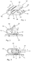
- FIGS 1 to 3 illustrate a first embodiment of a fixing device 12 in accordance with the present invention.
- the fixing device 12 has a body 14, which may be made from any suitable material but is conveniently made from plastics (one or more polymeric materials) by moulding or extrusion.
- the body 14 has a substantially rigid upper jaw member 18 pivotally mounted to a lower jaw member 20.
- the lower jaw member includes a substantially rigid and substantially planar lower jaw portion 50 for positioning beneath the rear edge region of a mat and an end portion 52 extending upwardly from a rear end of the lower jaw portion 50 for location about the rear edge 23 of the mat 24.
- the end portion 52 is arcuate, as shown in the Figures; and although substantially rigid, can flex to a limited extent.
- An aperture 26 for receiving a mat fixing lug 28 is provided in the lower jaw portion 50.
- the upper jaw member 18 is a substantially planar member which is pivotally connected to the end portion 52 of the lower jaw member 20 by means of a first live hinge 54.
- the upper jaw member 18 can be pivoted about the first live hinge 54 between a closed position as shown in Figures 1 and 3 , and an open position as shown in Figure 2 .
- the upper jaw member 18 projects at an angle upwardly away from the lower jaw portion 50.
- an edge region 23 of a vehicle mat 24 can be inserted between the upper and lower jaw members.
- the upper jaw member 18 In the closed position, the upper jaw member 18 overlies at least part of the lower jaw portion 50; and is aligned generally parallel to, or is inclined downwardly slightly towards, the lower jaw portion 50.
- the over-centre hinge mechanism 56 includes a first hinge member 58 connected rigidly with a rear edge of the upper jaw member 18.
- the first hinge member 58 is formed integrally with the upper jaw member 18 as an extension thereof.
- the first hinge member 58 projects downwardly at an obtuse angle ⁇ to the inner surface of the upper jaw member 18; and is configured so that it projects rearwardly when the upper jaw member 18 is in the closed position, and projects forwardly when the upper jaw member 18 is in the open position.
- the over-centre hinge 56 also includes a second hinge member 60 which projects upwardly from the lower jaw member 20, and is pivotally connected to the lower jaw member by means of a second live hinge 62. Inner ends of the first and second hinge members 58, 60 are radiused, and are connected together by means of a third live hinge 64.
- the first and second hinge members 58, 60 are both directed towards the rear of the body.
- the upper jaw member 18 is pivoted upwardly about the first live hinge 54.
- the first hinge member 58 rotates until it projects forwardly.
- the second hinge member 60 is also caused to pivot about the second live hinge 62 from a rearwardly directed position to a forwardly directed position as the upper jaw member is moved to the open position. During this movement, the radiused inner ends of the two hinge members 58, 60 roll over one another.
- the two hinge members 58, 60 In an intermediate position between the open and closed positions, the two hinge members 58, 60 will be aligned substantially vertically; so their combined length will be greater than the normal spacing between the rear edge of the upper jaw member 18 and the lower jaw member 20. To accommodate this, the end portion 52 is able to flex outwardly slightly. Accordingly, the upper jaw member 18 can be moved between the open and closed positions by applying a sufficient force to move the over-centre hinge members 58, 60 between their rearward and forward facing positions; but is otherwise held in either the open or the closed position.
- the upper and lower jaw members 18, 20 have mat engaging formations in the form of rearwardly directed teeth 32, which engage with the rear edge portion of a mat 24 placed between the upper and lower jaw members when the upper jaw member 18 is in the closed position.
- the rearwardly directed teeth 32 are located forwardly of the centre line (X-X, Fig. 3 ) of the mat fixing lug aperture 26. This is advantageous, as any forwardly directed force F 1 applied to the mat will tend to apply corresponding forces F 2 , F 3 to the teeth; which will tend to draw the upper jaw member 18 downwardly into tighter engagement with the mat.
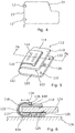
- Fig. 4 shows two fixing devices 12 attached to a rear edge of a mat 24, at suitable positions for location of the apertures 26 about fixing lugs 28 attached to a carpet of the vehicle. Once the fixing devices 12 are located on the mat fixing lugs and closed, they secure the mat in position, resisting forward movement of the mat during normal use of the vehicle.
- FIG. 5 A simplified view of a fixing device 112 for securing a mat 124 in a vehicle is shown in Figures 5 and 6 .
- the device 112 comprises a main body portion 114 and a separable, resilient clip 116.
- the main body 114 is a generally U-shaped component having substantially rigid, opposed upper and lower jaw members 118, 120 interconnected along their rear edges by means of a flexible, arcuate hinge member 122.
- the body portion 114 is designed to be placed about a rear edge portion 123 of a vehicle mat 124 as illustrated in Figure 6 , with the lower jaw member 120 positioned beneath the lower surface of the mat and the upper jaw member 118 positioned above the upper surface of the mat; and the hinge member 122 extending about the rear edge of the mat.
- An aperture 126 is provided in the lower jaw member 120, and is configured to receive a mat fixing lug (128, Fig. 6 ) affixed to a carpet 130 of the vehicle.
- the upper and lower jaw members 118, 120 of the body 114 have inwardly projecting mat engaging formations 132.
- the mat engaging formations 132 are in the form of conical teeth.
- the teeth 132 may be inserted into the fabric in use.
- the teeth or other formations may bite into the surfaces of the mat; or may engage with corresponding formations on the surfaces of the mat.
- the resilient clip 116 is also a generally U-shaped component having opposed upper and lower jaw members 134, 136 for engagement with outer surfaces of the upper and lower jaw members 118, 120 of the body portion 114 respectively.
- the resilient clip biases the upper and lower jaw members 118, 120 of the body portion towards each other to a closed position in which the jaw members 118, 120 grip a rear edge region of a mat 124 located between them.
- the resilient clip 116 is removed from the body 114, the upper and lower jaw members 118, 120 of the body can be moved apart to an open position to allow the body to be positioned about, or removed from, the rear edge 123 of a mat 124.
- Ridges 138 are provided along the inner edges of the upper and lower jaw members 134, 136 of the clip 116 for engagement in corresponding grooves 140 in the outer surfaces of the upper and lower jaw members 118, 120 of the body 114 when the clip is fully inserted about the body. Engagement of the ridges 138 in the grooves 140 releasably holds the clip 116 on the body 114 in use. It will be appreciated that other co-operating or mutually engaging formations could be provided for the same purpose.
- Ridges 142 are also provided on the outer surfaces of the upper and lower jaw members 134, 136 of the clip 116 to make it easier for a user to position the clip on the body and/or to remove the clip 116 from the body 114.
- the clip 116 is narrower than the body portion 114, and can be made of any suitable material.
- the clip 116 is made from a metallic material, such as spring steel.
- the body 114 may also be made from any suitable material, but may conveniently be manufactured from plastics by moulding or extrusion.
- the clip 116 is initially separated from the body 114.
- the upper and lower jaw members 118, 120 of the body 114 are moved apart to allow the body to be positioned about the rear edge region of a mat 124 with the upper jaw member 118 above the mat and the lower jaw member 120 below the mat.
- the clip 116 is then inserted over the rear end of the body 114 until the ridges 138 engage in the grooves 140.
- the clip 116 biases the upper and lower jaw members 118, 120 of the main body towards each other so that they grip the end region 123 of the mat.
- two fixing devices 112 are located in spaced relation along the rear edge of the mat at appropriate locations as shown in Figure 4 , so that when the mat 124 is positioned in the vehicle, mat fixing lugs 128 attached to the carpet of the vehicle engage in the apertures 126.
- the fixing devices 112 are held in position by the lugs 128; by gripping the rear edge region of the mat 124, they resist forward displacement of the mat in the foot well.
- the body members 114 could be located on the lugs 128 before the rear edge region of the mat 124 is inserted between the upper and lower jaw members 118, 120, and the clip 116 is applied.
- Fixing devices 12, 112 in accordance with the present invention can be used to secure a mat in a vehicle using the mat fixing lugs 28, 128 affixed to the vehicle carpet by the OEM, even where the mat is not provided with appropriate apertures for receiving the mat fixing lugs. This enables secure fitment of non-OEM mats, for example as may be supplied by vehicle dealers or other aftermarket outlets, overcoming many of the problems with the prior art arrangements. Fixing devices 12, 112 in accordance with the invention can be provided in a range of sizes to suit different mats.
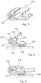
- FIGS 7 to 9 illustrate a further embodiment of a fixing device 212 in accordance with the present invention.
- the fixing device 212 in accordance with the second embodiment is similar to that of the first embodiment 12 described above, so only the differences will be described in detail.
- the fixing device 212 in accordance with the second embodiment differs from the first embodiment in that its over-centre hinge arrangement comprises a releasable locking detent arrangement 270 for releasably holding the upper jaw member 218 in the closed position.
- the releasable detent arrangement 270 includes a resilient clip formation 272 linked to the inner surface of the end portion 252 of the lower jaw member 220 by a first detent member 271, and a detent formation 274 mounted to the upper jaw member 218, detent 274 being releasably engaged in the clip 272 when the upper jaw member is in the closed position.
- Clip 272 is formed as an elongate C-section clip, in a shape complementary to detent formation 274, which is formed as an elongate partially cylindrical rib.
- Detent formation 274 is attached to the upper jaw member 118 by means of a first projection (or second detent member) 276 extending downwardly and rearwardly from the inner surface of the upper jaw member.
- Detent formation 274 is further supported by means of a second projection 278 extending upwardly and rearwardly from the lower jaw portion 250 of the lower jaw member 220.
- a second projection 278 extending upwardly and rearwardly from the lower jaw portion 250 of the lower jaw member 220.
- retention bars of a longitudinal cross-section equivalent to teeth 32, 132 may be substituted for said teeth.
- Such longitudinal bars could be made at least as effective as teeth; would be easier to make as part of an extruded fixing device; and would be less likely to hurt vehicle users if they put their fingers between the jaws for any reason.
- the body 14, 214 could be designed so that the lower jaw member 20, 220 is moved relative to the upper jaw member 18, 218 between open and closed positions.
Landscapes
- Engineering & Computer Science (AREA)
- Transportation (AREA)
- Mechanical Engineering (AREA)
- Passenger Equipment (AREA)
- Vehicle Cleaning, Maintenance, Repair, Refitting, And Outriggers (AREA)
Claims (15)
- Befestigungsvorrichtung (12, 112, 212) für eine Fußmatte (24, 124, 224) in einem Fahrzeug, wobei die Vorrichtung eine Clipanordnung zum Sichern einer Hinterkante (23, 123) einer Matte (24, 124, 224) aufweist und Mittel zum Sichern der Clipanordnung an einer Mattenbefestigungsformation (28, 128, 228) hat, welche an einem Teppichboden (30, 130, 230) des Fahrzeugs befestigt ist;
wobei die Vorrichtung einen Körper (14, 114) mit einem oberen (18, 118, 218) und einem diesem gegenüberliegenden unteren (20, 120, 220) Backenelement aufweist, zwischen denen ein Hinterkantenabschnitt (23, 123) einer Matte (24, 124, 224) aufgenommen werden kann, wobei der Körper (14, 114) eine Öffnung (26, 126) im unteren Backenelement (20, 120, 220) zum Aufnehmen einer Matten-Befestigungsöse (28, 128, 228) definiert, wobei wenigstens eines der Backenelemente zwischen einer geöffneten Backenposition und einer geschlossenen Backenposition bewegbar ist, wobei die Vorrichtung Mittel (56, 272, 274) zum lösbaren Halten der Backenelemente in der geschlossenen Position aufweist;
und wobei eines des oberen (18, 118, 218) und des unteren (20, 120, 220) Backenelements zum Bewegen zwischen einer geöffneten Backenposition und einer geschlossenen Backenposition schwenkbar an dem anderen des oberen und des unteren Backenelements befestigt ist; dadurch gekennzeichnet, dass:die Backenelemente über ein Übertotpunktscharnier (56) miteinander verbunden sind, welches konfiguriert ist, um eines des oberen (18, 118, 218) und des unteren (20, 120, 220) Backenelements in der geschlossenen Position lösbar zu halten. - Befestigungsvorrichtung (12, 112, 212) nach Anspruch 1, in der das obere Backenelement (18, 118, 218) für eine Bewegung zwischen einer geöffneten Backenposition und einer geschlossenen Backenposition schwenkbar an dem unteren Backenelement (20, 120, 220) befestigt ist.
- Befestigungsvorrichtung (112) nach Anspruch 1 oder 2, wobei die Vorrichtung einen lösbaren elastischen Clip (116) zum Eingreifen um den Körper (114) herum umfasst, um das obere (118) und das untere (120) Backenelement in die geschlossene Position vorzuspannen; und wobei der Clip (116) und der Körper (114) ineinander eingreifende Formationen (138, 140) zum lösbaren Sichern des Clips (116) an dem Körper (114) aufweisen.
- Befestigungsvorrichtung (112) nach Anspruch 3, wobei der Körper (114) aus einem Polymermaterial ausgebildet ist und der elastische Clip (116) aus einem metallischen Material ausgebildet ist.
- Befestigungsvorrichtung (12) nach einem der vorhergehenden Ansprüche, wobei das untere Backenelement (20) Folgendes umfasst: einen unteren Backenabschnitt (50) zum Positionieren unter der Hinterkantenregion (23) einer Matte (24) und einen Endabschnitt (52), der sich zum Anordnen um die Hinterkante (23) der Matte (24) herum von einem hinteren Ende des unteren Backenabschnitts (50) nach oben erstreckt, eine Hinterkante des oberen Backenelements (18), die über ein erstes Scharnier (54) schwenkbar an dem Endabschnitt (52) befestigt ist, wobei das Übertotpunktscharnier (56) einen ersten Scharnierabschnitt (58), der mit dem hinteren Ende des oberen Backenelements (18) verbunden ist und sich von dort in einem Winkel nach unten erstreckt, und einen zweiten Scharnierabschnitt (60), der über ein zweites Scharnier (62) schwenkbar mit einer Innenoberfläche des unteren Backenelements (20) verbunden ist und sich von dort nach oben erstreckt, wobei der erste (58) und der zweite (60) Übertotpunktscharnierabschnitt über ein drittes Scharnier (64) miteinander verbunden sind.
- Befestigungsvorrichtung (12) nach Anspruch 5, wobei die Vorrichtung derart ausgebildet ist, dass:wenn die obere Backe (18) in der geschlossenen Position ist, der erste (58) und der zweite (60) Übertotpunktscharnierabschnitt sich nach hinten zum Endabschnitt (52) hin erstrecken;und wenn das obere Backenelement (18) in der geöffneten Position ist, der erste (58) und der zweite (60) Übertotpunktscharnierabschnitt sich nach vorn vom Endabschnitt (52) weg erstrecken.
- Befestigungsvorrichtung (212) nach einem der vorhergehenden Ansprüche, wobei die Vorrichtung eine lösbare Rastanordnung (270) zum lösbaren Halten des einen des oberen (218) und des unteren (220) Backenelements in der geschlossenen Backenposition umfasst.
- Befestigungsvorrichtung (212) nach Anspruch 7, wobei das untere Backenelement (220) Folgendes umfasst: einen unteren Backenabschnitt (250) zum Platzieren unterhalb des Hinterkantenabschnitts einer Matte sowie einen Endabschnitt (252), der sich zum Anordnen um die Hinterkante der Matte herum von einem hinteren Ende des unteren Backenabschnitts (250) aus nach oben erstreckt, eine Hinterkante des oberen Backenelements (218), die über ein erstes Scharnier (254) schwenkbar an dem Endabschnitt (252) befestigt ist, wobei die lösbare Rastanordnung (270) ein erstes Rastelement (271) auf dem unteren Backenelement (220) und ein zweites Rastelement (276) auf dem oberen Backenelement (218) umfasst, wobei das erste und das zweite Rastelement entsprechende Formationen (272, 274) aufweisen, die in Eingriff treten, um das obere Backenelement (218) in der geschlossenen Position zu halten.
- Befestigungsvorrichtung (212) nach Anspruch 8, wobei das erste Rastelement (271) eine elastische Clipformation (272) am Endabschnitt (252) des unteren Backenelements (220) umfasst, wobei das zweite Rastelement (276) einen ersten Vorsprung umfasst, der sich von dem oberen Backenelement (218) nach unten und nach hinten hin erstreckt, wobei der Vorsprung eine Rastformation (274) aufweist, um mit der elastischen Clipformation (272) in Eingriff zu treten, wenn das obere Backenelement (218) in der geschlossenen Position ist.
- Befestigungsvorrichtung (212) nach Anspruch 9, wobei die Rastformation (274) ferner durch Mittel einer zweiten Formation (278) gestützt ist, welche sich von dem unteren Backenabschnitt (250) des unteren Backenelements (220) aus nach oben und nach hinten hin erstreckt.
- Befestigungsvorrichtung (12, 212) nach einem der Ansprüche 5 bis 10, wobei das erste (54, 254), das zweite (62) und das dritte (64) Scharnier Filmscharniere sind.
- Befestigungsvorrichtung (12, 212) nach Anspruch 11, wobei die Vorrichtung eine extrudierte Komponente ist.
- Befestigungsvorrichtung (12, 112, 212) nach einem der vorhergehenden Ansprüche, wobei das obere (18, 118, 218) und/oder das untere (20, 120, 220) Backenelement wenigstens eine Matteneingriffsformation (32, 132) aufweist.
- Befestigungsvorrichtung (12, 112, 212) nach Anspruch 13, wobei die wenigstens eine Matteneingriffsformation (32, 132) wenigstens einen Zahn aufweist.
- Befestigungsvorrichtung (12, 112, 212) nach Anspruch 14, wobei der wenigstens eine Zahn (32, 132) im Gebrauch nach hinten hin ausgerichtet ist.
Applications Claiming Priority (1)
| Application Number | Priority Date | Filing Date | Title |
|---|---|---|---|
| GB1120913.7A GB2497307A (en) | 2011-12-06 | 2011-12-06 | Vehicle floor mat fixing device |
Publications (2)
| Publication Number | Publication Date |
|---|---|
| EP2602153A1 EP2602153A1 (de) | 2013-06-12 |
| EP2602153B1 true EP2602153B1 (de) | 2016-04-27 |
Family
ID=45541249
Family Applications (1)
| Application Number | Title | Priority Date | Filing Date |
|---|---|---|---|
| EP12195392.1A Not-in-force EP2602153B1 (de) | 2011-12-06 | 2012-12-04 | Befestigungsvorrichtung für eine Fußmatte |
Country Status (3)
| Country | Link |
|---|---|
| EP (1) | EP2602153B1 (de) |
| ES (1) | ES2582323T3 (de) |
| GB (1) | GB2497307A (de) |
Families Citing this family (1)
| Publication number | Priority date | Publication date | Assignee | Title |
|---|---|---|---|---|
| CN114013354B (zh) * | 2021-12-21 | 2023-04-14 | 上汽通用汽车有限公司 | 一种车辆的地毯安装结构 |
Family Cites Families (8)
| Publication number | Priority date | Publication date | Assignee | Title |
|---|---|---|---|---|
| JPH046356Y2 (de) * | 1986-04-22 | 1992-02-21 | ||
| GB2271143B (en) * | 1992-08-28 | 1995-09-27 | Nifco Inc | Fixing device for sheet member |
| US5724703A (en) * | 1996-12-31 | 1998-03-10 | Wu; Sheng-Ho | Positioning device for positioning a mat in a car |
| US5775859A (en) * | 1997-06-06 | 1998-07-07 | National Molding Corp. | Mat fastener |
| DE19845663A1 (de) * | 1998-10-05 | 2000-04-13 | Daimler Chrysler Ag | Befestigungselement insbesondere zur Befestigung einer Einlegematte an einem Bodenbelag |
| WO2007131008A2 (en) * | 2006-05-04 | 2007-11-15 | Shell Oil Company | Apparatus for fastening an object |
| US8122567B2 (en) * | 2007-07-05 | 2012-02-28 | Connor Jr Mark A | Floor mat clip assembly |
| JP2011195071A (ja) * | 2010-03-23 | 2011-10-06 | Nifco Inc | フロアマット用クリップ |
-
2011
- 2011-12-06 GB GB1120913.7A patent/GB2497307A/en not_active Withdrawn
-
2012
- 2012-12-04 ES ES12195392.1T patent/ES2582323T3/es active Active
- 2012-12-04 EP EP12195392.1A patent/EP2602153B1/de not_active Not-in-force
Also Published As
| Publication number | Publication date |
|---|---|
| EP2602153A1 (de) | 2013-06-12 |
| GB201120913D0 (en) | 2012-01-18 |
| ES2582323T3 (es) | 2016-09-12 |
| GB2497307A (en) | 2013-06-12 |
Similar Documents
| Publication | Publication Date | Title |
|---|---|---|
| US8382182B2 (en) | Storage compartment having lid element | |
| US7445286B2 (en) | Child seat and belt system | |
| US9855871B2 (en) | Vehicle seat | |
| CN110897318B (zh) | 特别是用于电池组的背带 | |
| US8839494B1 (en) | Motorcycle boot strap | |
| US10442394B2 (en) | Belt tongue comprising a torsion bar | |
| US20110101055A1 (en) | Headrest hanger | |
| EP2727771B1 (de) | Fahrzeug mit einem Laderaum mit einer höhenverstellbaren Ladefläche | |
| AU2021200186B2 (en) | Belt adapter and holding system comprising a belt adapter and a carrier element | |
| WO2013145118A1 (ja) | バンド締付け具 | |
| WO2014089619A1 (en) | An anchorage device | |
| EP2602153B1 (de) | Befestigungsvorrichtung für eine Fußmatte | |
| EP1652442A1 (de) | Zungenabdeckung und diese verwendende Sicherheitsvorrichtung | |
| US8556338B1 (en) | Protective cover for vehicle seat back | |
| TW200815219A (en) | Apparatus for fastening an object | |
| EP1310410B1 (de) | Steckzunge eines Sicherheitsgurtes mit Griffvorrichtung | |
| US8801097B2 (en) | Anchor system for juvenile vehicle seat | |
| US5093958A (en) | Automobile floor mat anchoring system | |
| US20140361573A1 (en) | Ornamental Vehicle Floor Mat Cover | |
| DE60300755T2 (de) | Bodenmatte für Kraftfahrzeuge | |
| WO2017063043A1 (en) | Attachment for facilitating securing of a load with a strap, rope or the like | |
| EP2316691B1 (de) | Verkleidungsvorrichtung für Kraftfahrzeug und Verkleidungseinheit, die eine solche Vorrichtung umfasst | |
| US20020105168A1 (en) | Device for quick binding of a boot on a moving apparatus | |
| KR102201949B1 (ko) | 차량용 테일게이트 트림 일체형 안전 삼각대 보관구조 | |
| JPH0529943Y2 (de) |
Legal Events
| Date | Code | Title | Description |
|---|---|---|---|
| PUAI | Public reference made under article 153(3) epc to a published international application that has entered the european phase |
Free format text: ORIGINAL CODE: 0009012 |
|
| AK | Designated contracting states |
Kind code of ref document: A1 Designated state(s): AL AT BE BG CH CY CZ DE DK EE ES FI FR GB GR HR HU IE IS IT LI LT LU LV MC MK MT NL NO PL PT RO RS SE SI SK SM TR |
|
| AX | Request for extension of the european patent |
Extension state: BA ME |
|
| 17P | Request for examination filed |
Effective date: 20131212 |
|
| RBV | Designated contracting states (corrected) |
Designated state(s): AL AT BE BG CH CY CZ DE DK EE ES FI FR GB GR HR HU IE IS IT LI LT LU LV MC MK MT NL NO PL PT RO RS SE SI SK SM TR |
|
| RIC1 | Information provided on ipc code assigned before grant |
Ipc: B60N 3/06 20060101AFI20150828BHEP Ipc: B60N 3/04 20060101ALI20150828BHEP Ipc: A47G 27/04 20060101ALI20150828BHEP |
|
| GRAP | Despatch of communication of intention to grant a patent |
Free format text: ORIGINAL CODE: EPIDOSNIGR1 |
|
| INTG | Intention to grant announced |
Effective date: 20151110 |
|
| GRAS | Grant fee paid |
Free format text: ORIGINAL CODE: EPIDOSNIGR3 |
|
| GRAA | (expected) grant |
Free format text: ORIGINAL CODE: 0009210 |
|
| AK | Designated contracting states |
Kind code of ref document: B1 Designated state(s): AL AT BE BG CH CY CZ DE DK EE ES FI FR GB GR HR HU IE IS IT LI LT LU LV MC MK MT NL NO PL PT RO RS SE SI SK SM TR |
|
| REG | Reference to a national code |
Ref country code: GB Ref legal event code: FG4D |
|
| REG | Reference to a national code |
Ref country code: CH Ref legal event code: EP |
|
| REG | Reference to a national code |
Ref country code: AT Ref legal event code: REF Ref document number: 794358 Country of ref document: AT Kind code of ref document: T Effective date: 20160515 |
|
| REG | Reference to a national code |
Ref country code: IE Ref legal event code: FG4D |
|
| REG | Reference to a national code |
Ref country code: DE Ref legal event code: R096 Ref document number: 602012017602 Country of ref document: DE |
|
| REG | Reference to a national code |
Ref country code: LT Ref legal event code: MG4D |
|
| REG | Reference to a national code |
Ref country code: NL Ref legal event code: MP Effective date: 20160427 |
|
| REG | Reference to a national code |
Ref country code: ES Ref legal event code: FG2A Ref document number: 2582323 Country of ref document: ES Kind code of ref document: T3 Effective date: 20160912 |
|
| REG | Reference to a national code |
Ref country code: AT Ref legal event code: MK05 Ref document number: 794358 Country of ref document: AT Kind code of ref document: T Effective date: 20160427 |
|
| PG25 | Lapsed in a contracting state [announced via postgrant information from national office to epo] |
Ref country code: NL Free format text: LAPSE BECAUSE OF FAILURE TO SUBMIT A TRANSLATION OF THE DESCRIPTION OR TO PAY THE FEE WITHIN THE PRESCRIBED TIME-LIMIT Effective date: 20160427 |
|
| PG25 | Lapsed in a contracting state [announced via postgrant information from national office to epo] |
Ref country code: LT Free format text: LAPSE BECAUSE OF FAILURE TO SUBMIT A TRANSLATION OF THE DESCRIPTION OR TO PAY THE FEE WITHIN THE PRESCRIBED TIME-LIMIT Effective date: 20160427 Ref country code: FI Free format text: LAPSE BECAUSE OF FAILURE TO SUBMIT A TRANSLATION OF THE DESCRIPTION OR TO PAY THE FEE WITHIN THE PRESCRIBED TIME-LIMIT Effective date: 20160427 Ref country code: PL Free format text: LAPSE BECAUSE OF FAILURE TO SUBMIT A TRANSLATION OF THE DESCRIPTION OR TO PAY THE FEE WITHIN THE PRESCRIBED TIME-LIMIT Effective date: 20160427 Ref country code: NO Free format text: LAPSE BECAUSE OF FAILURE TO SUBMIT A TRANSLATION OF THE DESCRIPTION OR TO PAY THE FEE WITHIN THE PRESCRIBED TIME-LIMIT Effective date: 20160727 |
|
| PG25 | Lapsed in a contracting state [announced via postgrant information from national office to epo] |
Ref country code: SE Free format text: LAPSE BECAUSE OF FAILURE TO SUBMIT A TRANSLATION OF THE DESCRIPTION OR TO PAY THE FEE WITHIN THE PRESCRIBED TIME-LIMIT Effective date: 20160427 Ref country code: RS Free format text: LAPSE BECAUSE OF FAILURE TO SUBMIT A TRANSLATION OF THE DESCRIPTION OR TO PAY THE FEE WITHIN THE PRESCRIBED TIME-LIMIT Effective date: 20160427 Ref country code: PT Free format text: LAPSE BECAUSE OF FAILURE TO SUBMIT A TRANSLATION OF THE DESCRIPTION OR TO PAY THE FEE WITHIN THE PRESCRIBED TIME-LIMIT Effective date: 20160829 Ref country code: AT Free format text: LAPSE BECAUSE OF FAILURE TO SUBMIT A TRANSLATION OF THE DESCRIPTION OR TO PAY THE FEE WITHIN THE PRESCRIBED TIME-LIMIT Effective date: 20160427 Ref country code: LV Free format text: LAPSE BECAUSE OF FAILURE TO SUBMIT A TRANSLATION OF THE DESCRIPTION OR TO PAY THE FEE WITHIN THE PRESCRIBED TIME-LIMIT Effective date: 20160427 Ref country code: GR Free format text: LAPSE BECAUSE OF FAILURE TO SUBMIT A TRANSLATION OF THE DESCRIPTION OR TO PAY THE FEE WITHIN THE PRESCRIBED TIME-LIMIT Effective date: 20160728 Ref country code: HR Free format text: LAPSE BECAUSE OF FAILURE TO SUBMIT A TRANSLATION OF THE DESCRIPTION OR TO PAY THE FEE WITHIN THE PRESCRIBED TIME-LIMIT Effective date: 20160427 |
|
| PG25 | Lapsed in a contracting state [announced via postgrant information from national office to epo] |
Ref country code: IT Free format text: LAPSE BECAUSE OF FAILURE TO SUBMIT A TRANSLATION OF THE DESCRIPTION OR TO PAY THE FEE WITHIN THE PRESCRIBED TIME-LIMIT Effective date: 20160427 Ref country code: BE Free format text: LAPSE BECAUSE OF FAILURE TO SUBMIT A TRANSLATION OF THE DESCRIPTION OR TO PAY THE FEE WITHIN THE PRESCRIBED TIME-LIMIT Effective date: 20160427 |
|
| REG | Reference to a national code |
Ref country code: FR Ref legal event code: PLFP Year of fee payment: 5 |
|
| REG | Reference to a national code |
Ref country code: DE Ref legal event code: R097 Ref document number: 602012017602 Country of ref document: DE |
|
| PG25 | Lapsed in a contracting state [announced via postgrant information from national office to epo] |
Ref country code: DK Free format text: LAPSE BECAUSE OF FAILURE TO SUBMIT A TRANSLATION OF THE DESCRIPTION OR TO PAY THE FEE WITHIN THE PRESCRIBED TIME-LIMIT Effective date: 20160427 Ref country code: CZ Free format text: LAPSE BECAUSE OF FAILURE TO SUBMIT A TRANSLATION OF THE DESCRIPTION OR TO PAY THE FEE WITHIN THE PRESCRIBED TIME-LIMIT Effective date: 20160427 Ref country code: EE Free format text: LAPSE BECAUSE OF FAILURE TO SUBMIT A TRANSLATION OF THE DESCRIPTION OR TO PAY THE FEE WITHIN THE PRESCRIBED TIME-LIMIT Effective date: 20160427 Ref country code: SK Free format text: LAPSE BECAUSE OF FAILURE TO SUBMIT A TRANSLATION OF THE DESCRIPTION OR TO PAY THE FEE WITHIN THE PRESCRIBED TIME-LIMIT Effective date: 20160427 Ref country code: RO Free format text: LAPSE BECAUSE OF FAILURE TO SUBMIT A TRANSLATION OF THE DESCRIPTION OR TO PAY THE FEE WITHIN THE PRESCRIBED TIME-LIMIT Effective date: 20160427 |
|
| PG25 | Lapsed in a contracting state [announced via postgrant information from national office to epo] |
Ref country code: SM Free format text: LAPSE BECAUSE OF FAILURE TO SUBMIT A TRANSLATION OF THE DESCRIPTION OR TO PAY THE FEE WITHIN THE PRESCRIBED TIME-LIMIT Effective date: 20160427 |
|
| PLBE | No opposition filed within time limit |
Free format text: ORIGINAL CODE: 0009261 |
|
| STAA | Information on the status of an ep patent application or granted ep patent |
Free format text: STATUS: NO OPPOSITION FILED WITHIN TIME LIMIT |
|
| 26N | No opposition filed |
Effective date: 20170130 |
|
| PG25 | Lapsed in a contracting state [announced via postgrant information from national office to epo] |
Ref country code: SI Free format text: LAPSE BECAUSE OF FAILURE TO SUBMIT A TRANSLATION OF THE DESCRIPTION OR TO PAY THE FEE WITHIN THE PRESCRIBED TIME-LIMIT Effective date: 20160427 |
|
| REG | Reference to a national code |
Ref country code: CH Ref legal event code: PL |
|
| PG25 | Lapsed in a contracting state [announced via postgrant information from national office to epo] |
Ref country code: MC Free format text: LAPSE BECAUSE OF FAILURE TO SUBMIT A TRANSLATION OF THE DESCRIPTION OR TO PAY THE FEE WITHIN THE PRESCRIBED TIME-LIMIT Effective date: 20160427 |
|
| REG | Reference to a national code |
Ref country code: IE Ref legal event code: MM4A |
|
| PG25 | Lapsed in a contracting state [announced via postgrant information from national office to epo] |
Ref country code: LI Free format text: LAPSE BECAUSE OF NON-PAYMENT OF DUE FEES Effective date: 20161231 Ref country code: CH Free format text: LAPSE BECAUSE OF NON-PAYMENT OF DUE FEES Effective date: 20161231 Ref country code: LU Free format text: LAPSE BECAUSE OF NON-PAYMENT OF DUE FEES Effective date: 20161204 |
|
| PG25 | Lapsed in a contracting state [announced via postgrant information from national office to epo] |
Ref country code: IE Free format text: LAPSE BECAUSE OF NON-PAYMENT OF DUE FEES Effective date: 20161204 |
|
| REG | Reference to a national code |
Ref country code: FR Ref legal event code: PLFP Year of fee payment: 6 |
|
| PG25 | Lapsed in a contracting state [announced via postgrant information from national office to epo] |
Ref country code: HU Free format text: LAPSE BECAUSE OF FAILURE TO SUBMIT A TRANSLATION OF THE DESCRIPTION OR TO PAY THE FEE WITHIN THE PRESCRIBED TIME-LIMIT; INVALID AB INITIO Effective date: 20121204 Ref country code: CY Free format text: LAPSE BECAUSE OF FAILURE TO SUBMIT A TRANSLATION OF THE DESCRIPTION OR TO PAY THE FEE WITHIN THE PRESCRIBED TIME-LIMIT Effective date: 20160427 |
|
| PG25 | Lapsed in a contracting state [announced via postgrant information from national office to epo] |
Ref country code: TR Free format text: LAPSE BECAUSE OF FAILURE TO SUBMIT A TRANSLATION OF THE DESCRIPTION OR TO PAY THE FEE WITHIN THE PRESCRIBED TIME-LIMIT Effective date: 20160427 Ref country code: MK Free format text: LAPSE BECAUSE OF FAILURE TO SUBMIT A TRANSLATION OF THE DESCRIPTION OR TO PAY THE FEE WITHIN THE PRESCRIBED TIME-LIMIT Effective date: 20160427 Ref country code: IS Free format text: LAPSE BECAUSE OF FAILURE TO SUBMIT A TRANSLATION OF THE DESCRIPTION OR TO PAY THE FEE WITHIN THE PRESCRIBED TIME-LIMIT Effective date: 20160427 |
|
| PG25 | Lapsed in a contracting state [announced via postgrant information from national office to epo] |
Ref country code: BG Free format text: LAPSE BECAUSE OF FAILURE TO SUBMIT A TRANSLATION OF THE DESCRIPTION OR TO PAY THE FEE WITHIN THE PRESCRIBED TIME-LIMIT Effective date: 20160427 |
|
| PG25 | Lapsed in a contracting state [announced via postgrant information from national office to epo] |
Ref country code: MT Free format text: LAPSE BECAUSE OF NON-PAYMENT OF DUE FEES Effective date: 20161204 |
|
| PG25 | Lapsed in a contracting state [announced via postgrant information from national office to epo] |
Ref country code: AL Free format text: LAPSE BECAUSE OF FAILURE TO SUBMIT A TRANSLATION OF THE DESCRIPTION OR TO PAY THE FEE WITHIN THE PRESCRIBED TIME-LIMIT Effective date: 20160427 |
|
| REG | Reference to a national code |
Ref country code: DE Ref legal event code: R081 Ref document number: 602012017602 Country of ref document: DE Owner name: NISSAN MOTOR CO. LTD., JP Free format text: FORMER OWNER: NISSAN MOTOR MANUFACTURING (UK) LTD., CRANFIELD, BEDFORDSHIRE, GB |
|
| REG | Reference to a national code |
Ref country code: GB Ref legal event code: 732E Free format text: REGISTERED BETWEEN 20190503 AND 20190508 |
|
| REG | Reference to a national code |
Ref country code: ES Ref legal event code: PC2A Owner name: NISSAN MOTOR CO., LTD. Effective date: 20190717 |
|
| PGFP | Annual fee paid to national office [announced via postgrant information from national office to epo] |
Ref country code: GB Payment date: 20221116 Year of fee payment: 11 Ref country code: FR Payment date: 20221123 Year of fee payment: 11 Ref country code: DE Payment date: 20221122 Year of fee payment: 11 |
|
| PGFP | Annual fee paid to national office [announced via postgrant information from national office to epo] |
Ref country code: ES Payment date: 20230102 Year of fee payment: 11 |
|
| REG | Reference to a national code |
Ref country code: DE Ref legal event code: R119 Ref document number: 602012017602 Country of ref document: DE |
|
| GBPC | Gb: european patent ceased through non-payment of renewal fee |
Effective date: 20231204 |
|
| PG25 | Lapsed in a contracting state [announced via postgrant information from national office to epo] |
Ref country code: DE Free format text: LAPSE BECAUSE OF NON-PAYMENT OF DUE FEES Effective date: 20240702 |
|
| PG25 | Lapsed in a contracting state [announced via postgrant information from national office to epo] |
Ref country code: GB Free format text: LAPSE BECAUSE OF NON-PAYMENT OF DUE FEES Effective date: 20231204 |
|
| PG25 | Lapsed in a contracting state [announced via postgrant information from national office to epo] |
Ref country code: FR Free format text: LAPSE BECAUSE OF NON-PAYMENT OF DUE FEES Effective date: 20231231 |
|
| PG25 | Lapsed in a contracting state [announced via postgrant information from national office to epo] |
Ref country code: GB Free format text: LAPSE BECAUSE OF NON-PAYMENT OF DUE FEES Effective date: 20231204 Ref country code: FR Free format text: LAPSE BECAUSE OF NON-PAYMENT OF DUE FEES Effective date: 20231231 Ref country code: DE Free format text: LAPSE BECAUSE OF NON-PAYMENT OF DUE FEES Effective date: 20240702 |
|
| REG | Reference to a national code |
Ref country code: ES Ref legal event code: FD2A Effective date: 20250124 |
|
| PG25 | Lapsed in a contracting state [announced via postgrant information from national office to epo] |
Ref country code: ES Free format text: LAPSE BECAUSE OF NON-PAYMENT OF DUE FEES Effective date: 20231205 |