EP2599924A1 - Apparatus for fixing the rear glass of an operator cab on construction machinery - Google Patents
Apparatus for fixing the rear glass of an operator cab on construction machinery Download PDFInfo
- Publication number
- EP2599924A1 EP2599924A1 EP10855350.4A EP10855350A EP2599924A1 EP 2599924 A1 EP2599924 A1 EP 2599924A1 EP 10855350 A EP10855350 A EP 10855350A EP 2599924 A1 EP2599924 A1 EP 2599924A1
- Authority
- EP
- European Patent Office
- Prior art keywords
- glass
- cab
- rear glass
- window frame
- fixing portion
- Prior art date
- Legal status (The legal status is an assumption and is not a legal conclusion. Google has not performed a legal analysis and makes no representation as to the accuracy of the status listed.)
- Granted
Links
- 239000011521 glass Substances 0.000 title claims abstract description 132
- 238000010276 construction Methods 0.000 title claims abstract description 11
- 239000003292 glue Substances 0.000 description 4
- 241001391944 Commicarpus scandens Species 0.000 description 1
- 230000000694 effects Effects 0.000 description 1
Images


Classifications
-
- E—FIXED CONSTRUCTIONS
- E02—HYDRAULIC ENGINEERING; FOUNDATIONS; SOIL SHIFTING
- E02F—DREDGING; SOIL-SHIFTING
- E02F9/00—Component parts of dredgers or soil-shifting machines, not restricted to one of the kinds covered by groups E02F3/00 - E02F7/00
- E02F9/16—Cabins, platforms, or the like, for drivers
-
- B—PERFORMING OPERATIONS; TRANSPORTING
- B60—VEHICLES IN GENERAL
- B60J—WINDOWS, WINDSCREENS, NON-FIXED ROOFS, DOORS, OR SIMILAR DEVICES FOR VEHICLES; REMOVABLE EXTERNAL PROTECTIVE COVERINGS SPECIALLY ADAPTED FOR VEHICLES
- B60J1/00—Windows; Windscreens; Accessories therefor
- B60J1/004—Mounting of windows
- B60J1/006—Mounting of windows characterised by fixation means such as clips, adhesive, etc.
-
- B—PERFORMING OPERATIONS; TRANSPORTING
- B60—VEHICLES IN GENERAL
- B60J—WINDOWS, WINDSCREENS, NON-FIXED ROOFS, DOORS, OR SIMILAR DEVICES FOR VEHICLES; REMOVABLE EXTERNAL PROTECTIVE COVERINGS SPECIALLY ADAPTED FOR VEHICLES
- B60J1/00—Windows; Windscreens; Accessories therefor
- B60J1/18—Windows; Windscreens; Accessories therefor arranged at the vehicle rear
- B60J1/1838—Windows; Windscreens; Accessories therefor arranged at the vehicle rear movable for non-convertible vehicles, including vehicles with versatile load area
-
- B—PERFORMING OPERATIONS; TRANSPORTING
- B62—LAND VEHICLES FOR TRAVELLING OTHERWISE THAN ON RAILS
- B62D—MOTOR VEHICLES; TRAILERS
- B62D25/00—Superstructure or monocoque structure sub-units; Parts or details thereof not otherwise provided for
- B62D25/04—Door pillars ; windshield pillars
-
- B—PERFORMING OPERATIONS; TRANSPORTING
- B66—HOISTING; LIFTING; HAULING
- B66C—CRANES; LOAD-ENGAGING ELEMENTS OR DEVICES FOR CRANES, CAPSTANS, WINCHES, OR TACKLES
- B66C13/00—Other constructional features or details
- B66C13/52—Details of compartments for driving engines or motors or of operator's stands or cabins
- B66C13/54—Operator's stands or cabins
-
- E—FIXED CONSTRUCTIONS
- E02—HYDRAULIC ENGINEERING; FOUNDATIONS; SOIL SHIFTING
- E02F—DREDGING; SOIL-SHIFTING
- E02F9/00—Component parts of dredgers or soil-shifting machines, not restricted to one of the kinds covered by groups E02F3/00 - E02F7/00
- E02F9/16—Cabins, platforms, or the like, for drivers
- E02F9/163—Structures to protect drivers, e.g. cabins, doors for cabins; Falling object protection structure [FOPS]; Roll over protection structure [ROPS]
-
- E—FIXED CONSTRUCTIONS
- E02—HYDRAULIC ENGINEERING; FOUNDATIONS; SOIL SHIFTING
- E02F—DREDGING; SOIL-SHIFTING
- E02F9/00—Component parts of dredgers or soil-shifting machines, not restricted to one of the kinds covered by groups E02F3/00 - E02F7/00
- E02F9/24—Safety devices, e.g. for preventing overload
-
- E—FIXED CONSTRUCTIONS
- E05—LOCKS; KEYS; WINDOW OR DOOR FITTINGS; SAFES
- E05B—LOCKS; ACCESSORIES THEREFOR; HANDCUFFS
- E05B65/00—Locks or fastenings for special use
- E05B65/0025—Locks or fastenings for special use for glass wings
-
- E—FIXED CONSTRUCTIONS
- E05—LOCKS; KEYS; WINDOW OR DOOR FITTINGS; SAFES
- E05B—LOCKS; ACCESSORIES THEREFOR; HANDCUFFS
- E05B65/00—Locks or fastenings for special use
- E05B65/10—Locks or fastenings for special use for panic or emergency doors
- E05B65/1033—Locks or fastenings for special use for panic or emergency doors emergency release of windows, window grills, escape hatches or the like
-
- E—FIXED CONSTRUCTIONS
- E05—LOCKS; KEYS; WINDOW OR DOOR FITTINGS; SAFES
- E05C—BOLTS OR FASTENING DEVICES FOR WINGS, SPECIALLY FOR DOORS OR WINDOWS
- E05C3/00—Fastening devices with bolts moving pivotally or rotatively
- E05C3/004—Fastening devices with bolts moving pivotally or rotatively about an axis perpendicular to the surface on which the fastener is mounted
Definitions
- the present invention relates to an apparatus for fixing the rear glass of a cab on construction machinery. More particularly, the present invention relates to an apparatus for fixing a rear glass of a cab on construction machinery, which allows for easy detachment of the glass in the event of an emergency escape, and thus enables an operator in the cab to easily escape from the cab when an emergency situation occurs.
- FIG. 1 is a perspective view illustrating a cab 2 and a hammer 1 for an emergency escape put on a side surface of a rear glass of the cab 2 in the related art.
- the hammer 1 for an emergency escape may be lost, and even if the hammer 1 is used, it is not easy to break the rear glass, and this causes difficulty in escaping rapidly. Further, the operator may be injured with the pieces of the rear glass broken by the hammer 1.
- Fig. 2 is a perspective view illustrating a fixing device in the related art that fixes a rear glass 3 of a cab 2 using a seal 5.
- a special tool is used to cause large expenses, and an operator is unable to directly replace the rear glass.
- the reference numeral "4" denotes a decal that indicates an emergency escape.
- Fig. 3 is a perspective view illustrating a fixing device in the related art that fixes a rear glass 3 of a cab 2 using glue 6.
- glue 6 glue 6
- the present invention has been made to solve the above-mentioned problems occurring in the related art, and one embodiment of the present invention is related to an apparatus for fixing a rear glass of a cab on construction machinery, which allows for easy detachment of the glass without using a separate hammer for an emergency escape to enable an operator to rapidly escape from the cab when an emergency situation occurs, and which enables the operator to directly replace the rear glass to save rear glass replacement costs and time.
- an apparatus for fixing the rear glass of a cab on construction machinery that allows for easy detachment of the glass in the event of an emergency escape, which includes a window frame forming a cab window frame; a weather strip coupled to the window frame to seal a gap between the window frame and the rear glass of the cab; a glass interior fixing portion including an engagement portion inserted and engaged between the window frame and the weather strip, a body portion extending from the engagement portion at right angles and having a groove so that the body portion can be broken by an external impact, and a glass support portion supporting the rear glass of the cab; a glass exterior fixing portion engaged with the glass support portion of the glass interior fixing portion to support the rear glass of the cab; and a stopper having one side fixed to the window frame to support the rear glass of the cab.
- the groove provided in the body portion of the glass interior fixing portion has a "V"-shaped cross-section.
- the glass support portion of the glass interior fixing portion may have an engagement hole and may be engaged with the glass exterior fixing portion.
- the stopper may include a main body portion supporting the rear glass of the cab, a main body support portion extending from the main body portion at right angles and fixed to one side of the window frame, and a glass seat portion which is formed inside the main body support portion and on which the rear glass of the cab is seated.
- the rear glass can be easily taken away without using the separate hammer for an emergency escape to enable the operator to rapidly escape from the cab when an emergency situation occurs, and the operator can directly replace the rear glass to save the rear glass replacement costs and time.
- the operator can be prevented from being injured with the pieces of the broken rear glass. Further, it is possible to immediately replace the rear glass regardless of the seasons or places, and thus the construction equipment is able to operate immediately after the replacement.
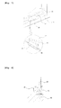
- Figs. 4(a) and 4(b) are perspective views illustrating an apparatus for fixing a rear glass of a cab mounted according to an embodiment of the present invention as seen from an inside of the cab and as seen from an outside of the cab.
- a decal 31 is attached to a rear glass 30 in a cab to indicate that an emergency escape is possible.
- a glass interior fixing portion 40 is engaged with a window frame 10 to support the rear glass 30.
- a window frame 10 a glass exterior fixing portion 50, and a stopper 60 are provided on the outside of the cab.
- Fig. 5 is a perspective view illustrating a glass interior fixing portion 40 and the glass exterior fixing portion 50 of the rear glass of the cab according to the present invention.
- the glass interior fixing portion 40 may include an engagement portion 41 inserted and engaged in a space between the window frame 10 and the weather strip 20, a body portion 42 extending from the engagement portion at right angles and having a groove 41 so that the body portion can be broken by an external impact, and a glass support portion 44 supporting the rear glass 30 of the cab.
- the glass support portion 44 has an engagement hole 45 formed therein, and is engaged with the glass exterior fixing portion 50.
- the rear glass 30 can be fixed using the glass interior fixing portion 40 and the glass exterior fixing portion 50.
- the glass exterior fixing portion 50 is engaged with the engagement hole 45 of the glass interior fixing portion 40, and the engagement portion 41 of the glass interior fixing portion 40 is engaged between the window frame 10 and the weather strip 20, so that the glass support portion 44 can support the rear glass 30 of the cab.
- the glass exterior fixing portion 50 can be engaged in the engagement hole 45 of the glass interior fixing portion 40 as a bolt and a nut. That is, a screw thread may be formed inside the engagement hole 45 of the glass interior fixing portion 40, and by turning the glass exterior fixing portion 50, the glass exterior fixing portion 50 may be screw-engaged in the engagement hole 45 of the glass interior fixing portion 40.
- Fig. 6 is a cross-sectional view illustrating the rear glass fixed using the apparatus for fixing the rear glass.
- the glass exterior fixing portion 50 is engaged in the engagement hole 45 of the glass interior fixing portion 40, and the engagement portion 41 of the glass interior fixing portion 40 is engaged between the window frame 10 and the weather strip 20, so that the glass support portion 44 can support the rear glass 30 of the cab.
- Fig. 7 is a perspective view illustrating the rear glass 30 of the cab on which a stopper is mounted.
- the stopper 60 is engaged with the window frame 10, and as shown in an enlarged view of the stopper 60 and the rear glass 30 that is seated on the stopper 60, the stopper 60 may include a main body portion 61 supporting the rear glass 30 of the cab, a main body support portion 62 extending from the main body portion at right angles and fixed to one side of the window frame 10, and a glass seat portion 63 formed inside the main body support portion 62.
- the rear glass 30 may be seated on the glass seat portion 63.
- Fig. 8 is a cross-sectional view of the rear glass 30 seated between the stopper 60 and the weather strip 20. Since the stopper 60 supports the rear glass 30, it functions to prevent the rear glass 30 from being pushed to the outside.
Landscapes
- Engineering & Computer Science (AREA)
- Mechanical Engineering (AREA)
- Mining & Mineral Resources (AREA)
- Civil Engineering (AREA)
- General Engineering & Computer Science (AREA)
- Structural Engineering (AREA)
- Business, Economics & Management (AREA)
- Emergency Management (AREA)
- Chemical & Material Sciences (AREA)
- Combustion & Propulsion (AREA)
- Transportation (AREA)
- Window Of Vehicle (AREA)
- Component Parts Of Construction Machinery (AREA)
Abstract
Description
- The present invention relates to an apparatus for fixing the rear glass of a cab on construction machinery. More particularly, the present invention relates to an apparatus for fixing a rear glass of a cab on construction machinery, which allows for easy detachment of the glass in the event of an emergency escape, and thus enables an operator in the cab to easily escape from the cab when an emergency situation occurs.
- If an accident, such as overturn of construction equipment, occurs in a construction spot, an operator breaks a rear glass of a cab to escape from the cab. Conventionally, in order to escape through the rear glass, the operator breaks the rear glass of the cab using a hammer for an emergency escape that is put on a hammer hanger, removes pieces of broken glass, and then escapes through the broken glass window.
Fig. 1 is a perspective view illustrating acab 2 and ahammer 1 for an emergency escape put on a side surface of a rear glass of thecab 2 in the related art. However, thehammer 1 for an emergency escape may be lost, and even if thehammer 1 is used, it is not easy to break the rear glass, and this causes difficulty in escaping rapidly. Further, the operator may be injured with the pieces of the rear glass broken by thehammer 1. -
Fig. 2 is a perspective view illustrating a fixing device in the related art that fixes arear glass 3 of acab 2 using aseal 5. In the case of fixing the rear glass using theseal 5, a special tool is used to cause large expenses, and an operator is unable to directly replace the rear glass. The reference numeral "4" denotes a decal that indicates an emergency escape. -
Fig. 3 is a perspective view illustrating a fixing device in the related art that fixes arear glass 3 of acab 2 using glue 6. In the case of reattaching the broken rear glass using the glue 6, it takes time to dry the glue 6 that fixes the rear glass, and thus the construction equipment is unable to operate immediately. Particularly, in the winter season or cold weather, it is much more difficult to replace the rear glass. - Therefore, the present invention has been made to solve the above-mentioned problems occurring in the related art, and one embodiment of the present invention is related to an apparatus for fixing a rear glass of a cab on construction machinery, which allows for easy detachment of the glass without using a separate hammer for an emergency escape to enable an operator to rapidly escape from the cab when an emergency situation occurs, and which enables the operator to directly replace the rear glass to save rear glass replacement costs and time.
- In accordance with an aspect of the present invention, there is provided an apparatus for fixing the rear glass of a cab on construction machinery that allows for easy detachment of the glass in the event of an emergency escape, which includes a window frame forming a cab window frame; a weather strip coupled to the window frame to seal a gap between the window frame and the rear glass of the cab; a glass interior fixing portion including an engagement portion inserted and engaged between the window frame and the weather strip, a body portion extending from the engagement portion at right angles and having a groove so that the body portion can be broken by an external impact, and a glass support portion supporting the rear glass of the cab; a glass exterior fixing portion engaged with the glass support portion of the glass interior fixing portion to support the rear glass of the cab; and a stopper having one side fixed to the window frame to support the rear glass of the cab.
- It is preferable that the groove provided in the body portion of the glass interior fixing portion has a "V"-shaped cross-section.
- The glass support portion of the glass interior fixing portion may have an engagement hole and may be engaged with the glass exterior fixing portion.
- The stopper may include a main body portion supporting the rear glass of the cab, a main body support portion extending from the main body portion at right angles and fixed to one side of the window frame, and a glass seat portion which is formed inside the main body support portion and on which the rear glass of the cab is seated.
- According to an embodiment of the present invention as described above, the rear glass can be easily taken away without using the separate hammer for an emergency escape to enable the operator to rapidly escape from the cab when an emergency situation occurs, and the operator can directly replace the rear glass to save the rear glass replacement costs and time.
- Further, even in the case where the operator breaks the rear glass using the hammer to escape from the cab, the operator can be prevented from being injured with the pieces of the broken rear glass. Further, it is possible to immediately replace the rear glass regardless of the seasons or places, and thus the construction equipment is able to operate immediately after the replacement.
- The above objects, other features and advantages of the present invention will become more apparent by describing the preferred embodiments thereof with reference to the accompanying drawings, in which:
-
Fig. 1 is a perspective view illustrating a cab and a hammer for an emergency escape; -
Fig. 2 is a perspective view illustrating a cap rear glass in the related art fixed using a seal; -
Fig. 3 is a perspective view illustrating a rear glass of a cab in the related art fixed using glue; - Figs. 4(a) and 4(b) are perspective views illustrating an apparatus for fixing a rear glass of a cab mounted according to an embodiment of the present invention as seen from an inside of the cab and as seen from an outside of the cab;
-
Fig. 5 is a perspective view illustrating a glass interior fixing portion and a glass exterior fixing portion of a rear glass of a cab according to the present invention; -
Fig. 6 is a cross-sectional view illustrating a rear glass fixed using the apparatus for fixing the rear glass; -
Fig. 7 is a perspective view illustrating a rear glass of a cab on which a stopper is mounted; and -
Fig. 8 is a cross-sectional view of a rear glass on which a stopper is mounted. - Hereinafter, a preferred embodiment of the present invention will be described in detail with reference to the accompanying drawings.
-
Figs. 4(a) and 4(b) are perspective views illustrating an apparatus for fixing a rear glass of a cab mounted according to an embodiment of the present invention as seen from an inside of the cab and as seen from an outside of the cab. Referring toFig. 4(a) , adecal 31 is attached to arear glass 30 in a cab to indicate that an emergency escape is possible. Further, a glassinterior fixing portion 40 is engaged with awindow frame 10 to support therear glass 30. Referring toFig. 4(b), awindow frame 10, a glassexterior fixing portion 50, and astopper 60 are provided on the outside of the cab. -
Fig. 5 is a perspective view illustrating a glassinterior fixing portion 40 and the glassexterior fixing portion 50 of the rear glass of the cab according to the present invention. Referring toFig. 5 , the glassinterior fixing portion 40 may include anengagement portion 41 inserted and engaged in a space between thewindow frame 10 and theweather strip 20, abody portion 42 extending from the engagement portion at right angles and having agroove 41 so that the body portion can be broken by an external impact, and aglass support portion 44 supporting therear glass 30 of the cab. - If an impact is applied from the outside to the glass
interior fixing portion 40, the portion of thegroove 43, which is weak against the impact, is easily broken. If the portion of thegroove 43 is broken due to the external impact applied to thebody portion 42 of the glassinterior fixing portion 40, therear glass 30 can be easily taken away when an emergency situation occurs. Theglass support portion 44 has anengagement hole 45 formed therein, and is engaged with the glassexterior fixing portion 50. - The
rear glass 30 can be fixed using the glassinterior fixing portion 40 and the glassexterior fixing portion 50. The glassexterior fixing portion 50 is engaged with theengagement hole 45 of the glassinterior fixing portion 40, and theengagement portion 41 of the glassinterior fixing portion 40 is engaged between thewindow frame 10 and theweather strip 20, so that theglass support portion 44 can support therear glass 30 of the cab. - The glass
exterior fixing portion 50 can be engaged in theengagement hole 45 of the glassinterior fixing portion 40 as a bolt and a nut. That is, a screw thread may be formed inside theengagement hole 45 of the glassinterior fixing portion 40, and by turning the glassexterior fixing portion 50, the glassexterior fixing portion 50 may be screw-engaged in theengagement hole 45 of the glassinterior fixing portion 40. -
Fig. 6 is a cross-sectional view illustrating the rear glass fixed using the apparatus for fixing the rear glass. The glassexterior fixing portion 50 is engaged in theengagement hole 45 of the glassinterior fixing portion 40, and theengagement portion 41 of the glassinterior fixing portion 40 is engaged between thewindow frame 10 and theweather strip 20, so that theglass support portion 44 can support therear glass 30 of the cab. -
Fig. 7 is a perspective view illustrating therear glass 30 of the cab on which a stopper is mounted. Referring toFIG. 7 , thestopper 60 is engaged with thewindow frame 10, and as shown in an enlarged view of thestopper 60 and therear glass 30 that is seated on thestopper 60, thestopper 60 may include amain body portion 61 supporting therear glass 30 of the cab, a mainbody support portion 62 extending from the main body portion at right angles and fixed to one side of thewindow frame 10, and aglass seat portion 63 formed inside the mainbody support portion 62. Therear glass 30 may be seated on theglass seat portion 63. -
Fig. 8 is a cross-sectional view of therear glass 30 seated between thestopper 60 and theweather strip 20. Since thestopper 60 supports therear glass 30, it functions to prevent therear glass 30 from being pushed to the outside. - Although preferred embodiments of the present invention have been described for illustrative purposes, the present invention is not limited to the above-described specific embodiments, and those of ordinary skill in the art to which the present invention pertains will appreciate various changed in form and detail may be made therein without departing from the spirit and scope of the invention as defined by the appended claims. Further, the items that can be easily analogized from the accompanying drawings, although not described in the detailed description, should be considered to be included in the contents of the present invention, and various modified embodiments should not be understood separately from the technical idea or prospect of the present invention.
Claims (4)
- An apparatus for fixing the rear glass of a cab on construction machinery that allows for easy detachment of the glass in the event of an emergency escape, comprising:a window frame forming a cab window frame;a weather strip coupled to the window frame to seal a gap between the window frame and the rear glass of the cab;a glass interior fixing portion including an engagement portion inserted and engaged between the window frame and the weather strip, a body portion extending from the engagement portion at right angles and having a groove so that the body portion can be broken by an external impact, and a glass support portion supporting the rear glass of the cab;a glass exterior fixing portion engaged with the glass support portion of the glass interior fixing portion to support the rear glass of the cab; anda stopper having one side fixed to the window frame to support the rear glass of the cab.
- The apparatus according to claim 1, wherein the groove provided in the body portion of the glass interior fixing portion has a "V"-shaped cross-section.
- The apparatus according to claim 1, wherein the glass support portion of the glass interior fixing portion has an engagement hole and is engaged with the glass exterior fixing portion.
- The apparatus according to claim 1, wherein the stopper comprises a main body portion supporting the rear glass of the cab, a main body support portion extending from the main body portion at right angles and fixed to one side of the window frame, and a glass seat portion which is formed inside the main body support portion and on which the rear glass of the cab is seated.
Applications Claiming Priority (1)
| Application Number | Priority Date | Filing Date | Title |
|---|---|---|---|
| PCT/KR2010/004946 WO2012015078A1 (en) | 2010-07-28 | 2010-07-28 | Apparatus for fixing the rear glass of an operator cab on construction machinery |
Publications (3)
| Publication Number | Publication Date |
|---|---|
| EP2599924A1 true EP2599924A1 (en) | 2013-06-05 |
| EP2599924A4 EP2599924A4 (en) | 2015-03-04 |
| EP2599924B1 EP2599924B1 (en) | 2016-07-06 |
Family
ID=45530270
Family Applications (1)
| Application Number | Title | Priority Date | Filing Date |
|---|---|---|---|
| EP10855350.4A Not-in-force EP2599924B1 (en) | 2010-07-28 | 2010-07-28 | Apparatus for fixing the rear glass of an operator cab on construction machinery |
Country Status (6)
| Country | Link |
|---|---|
| US (1) | US9021764B2 (en) |
| EP (1) | EP2599924B1 (en) |
| JP (1) | JP5608289B2 (en) |
| KR (1) | KR101763278B1 (en) |
| CN (1) | CN103025965B (en) |
| WO (1) | WO2012015078A1 (en) |
Families Citing this family (10)
| Publication number | Priority date | Publication date | Assignee | Title |
|---|---|---|---|---|
| CN103732836B (en) * | 2011-08-16 | 2016-03-09 | 沃尔沃建造设备有限公司 | Equipment for fixing the lower glass of the construction machinery cab |
| DE102013107559A1 (en) * | 2013-07-16 | 2015-01-22 | Maschinenfabrik Reinhausen Gmbh | Bursting device for a high voltage device |
| JP5945986B2 (en) * | 2014-08-19 | 2016-07-05 | 株式会社豊田自動織機 | Automotive back door structure |
| US10596989B2 (en) | 2016-05-12 | 2020-03-24 | Westinghouse Air Brake Technologies Corporation | Driver's barrier door with powered window |
| KR102568539B1 (en) | 2017-04-19 | 2023-08-18 | 클라크 이큅먼트 컴파니 | loader cap |
| CN109017231B (en) * | 2018-06-27 | 2020-04-24 | 长安大学 | Emergency escape device for large passenger car accidents |
| JP7012038B2 (en) * | 2019-03-08 | 2022-01-27 | 日立建機株式会社 | Work machine |
| JP1655685S (en) * | 2019-07-05 | 2020-03-23 | ||
| US11731717B2 (en) | 2020-02-26 | 2023-08-22 | Caterpillar Inc. | Spacer tool |
| US12589979B2 (en) | 2023-12-29 | 2026-03-31 | Lds Holdings Llc | Forklift cab enclosure system |
Family Cites Families (33)
| Publication number | Priority date | Publication date | Assignee | Title |
|---|---|---|---|---|
| DE1017925B (en) * | 1955-06-27 | 1957-10-17 | Deutsche Bundespost | Rubber profile window frames for motor vehicles and rail vehicles |
| FR2049261A5 (en) * | 1969-06-05 | 1971-03-26 | Peugeot & Renault | |
| US3808742A (en) * | 1972-09-20 | 1974-05-07 | Adams & Westlake Co | Window |
| US3822462A (en) * | 1972-11-08 | 1974-07-09 | Faircroft Eng Inc | Method of constructing door and window structures |
| FR2311672A1 (en) * | 1975-05-23 | 1976-12-17 | Klein Ets Georges | Safety device for vehicle window - has window glass and frame held under pressure by toggle assembly which can be released |
| US4027436A (en) * | 1976-03-15 | 1977-06-07 | Walcon Corporation | Explosion venting wall structure with releasable fastener means |
| GB2049010A (en) * | 1979-02-21 | 1980-12-17 | British Leyland Cars Ltd | Improvements relating to vehicle windows |
| US4272931A (en) * | 1979-05-21 | 1981-06-16 | Stanizzo John A | Prefabricated shell assembly for window trim |
| US4364209A (en) * | 1980-08-20 | 1982-12-21 | Gebhard Paul C | Window glazing system |
| DE3114941C2 (en) * | 1981-04-13 | 1983-07-28 | Jansens & Dieperink B.V., 1505 Zaandam | Explosion lock plate |
| DE3307021A1 (en) * | 1983-02-28 | 1984-09-06 | Vereinigte Glaswerke Gmbh, 5100 Aachen | FASTENING ARRANGEMENT FOR VEHICLE WINDOWS |
| DE4018925A1 (en) | 1990-06-13 | 1991-12-19 | Leybold Ag | INDUCTION MELTING OVENS |
| JP2551459Y2 (en) * | 1991-07-22 | 1997-10-22 | 株式会社小松製作所 | Sliding window glass fixing device |
| DE4238490C1 (en) * | 1992-11-14 | 1994-03-10 | Daimler Benz Ag | Insulating glazing with emergency exit for a window opening of a motor vehicle |
| JP2584422Y2 (en) * | 1992-12-14 | 1998-11-05 | 日立建機株式会社 | Operator's cab of construction machinery |
| KR0128517Y1 (en) * | 1994-02-28 | 1998-11-02 | 김무 | Heavy Duty Glass Fixture with Removable Holder |
| KR0140800Y1 (en) * | 1993-06-29 | 1999-04-01 | 토니헬샴 | Cabin's cab having a detachable lower glass |
| JPH0730110U (en) * | 1993-11-11 | 1995-06-06 | 新キャタピラー三菱株式会社 | Emergency glass window mounting structure |
| KR970007051B1 (en) | 1994-02-24 | 1997-05-02 | 김영대 | Filtration cylinder cleaning device of multi screw glass for dirt dewatering |
| JP3408858B2 (en) * | 1994-02-28 | 2003-05-19 | 日立建機株式会社 | Construction machinery |
| CA2149279C (en) | 1994-05-13 | 1999-06-01 | Osamu Tanaka | Annealing separator having excellent reactivity for grain-oriented electrical steel sheet and method of use the same |
| KR0123820Y1 (en) * | 1994-05-31 | 1998-08-17 | 김무 | Heavy Duty Glass Fixtures |
| DE19632610A1 (en) * | 1996-08-13 | 1998-02-19 | Dynamit Nobel Ag | Emergency release system for window of high-speed train |
| KR19980013853U (en) * | 1996-08-31 | 1998-06-05 | 김무 | Front lower window detachment device of excavator cab |
| US5950370A (en) * | 1997-03-20 | 1999-09-14 | Cr/Pl, L.L.C. | Bathtub support and sealing flange |
| JPH1143297A (en) * | 1997-07-24 | 1999-02-16 | Nippon Yusoki Co Ltd | Forklift with cabin |
| US6088979A (en) * | 1997-10-27 | 2000-07-18 | Neal; Murray | Frame for supporting an auxiliary glazing and method for installing the improved frame |
| DE60102465T2 (en) * | 2000-04-27 | 2005-01-27 | Asahi Glass Co., Ltd. | Mounting structure for a window glass and removal method for a window glass |
| JP2002067685A (en) * | 2000-08-25 | 2002-03-08 | Asahi Glass Co Ltd | Vehicle window material assembly structure |
| JP3682436B2 (en) * | 2002-02-08 | 2005-08-10 | ボルボ コンストラクション イクイップメント ホールディング スウェーデン アーベー | Heavy equipment cab lower glass storage mechanism |
| FR2870273B1 (en) * | 2004-05-11 | 2008-04-11 | Rene Philippe Ruhlmann | DEVICE FOR MAINTAINING A FALSE CEILING OR FALSE FLOOR. |
| JP4326421B2 (en) * | 2004-07-23 | 2009-09-09 | 株式会社クボタ | Door mounting column for traveling vehicle cabin |
| US7299597B2 (en) * | 2005-03-31 | 2007-11-27 | Lawrence Ray Holt | Construction clip |
-
2010
- 2010-07-28 WO PCT/KR2010/004946 patent/WO2012015078A1/en not_active Ceased
- 2010-07-28 JP JP2013521663A patent/JP5608289B2/en not_active Expired - Fee Related
- 2010-07-28 US US13/812,182 patent/US9021764B2/en not_active Expired - Fee Related
- 2010-07-28 CN CN201080068254.7A patent/CN103025965B/en not_active Expired - Fee Related
- 2010-07-28 EP EP10855350.4A patent/EP2599924B1/en not_active Not-in-force
- 2010-07-28 KR KR1020127033044A patent/KR101763278B1/en not_active Expired - Fee Related
Also Published As
| Publication number | Publication date |
|---|---|
| CN103025965B (en) | 2015-08-12 |
| US20130125483A1 (en) | 2013-05-23 |
| US9021764B2 (en) | 2015-05-05 |
| KR101763278B1 (en) | 2017-07-31 |
| EP2599924A4 (en) | 2015-03-04 |
| JP2013533406A (en) | 2013-08-22 |
| JP5608289B2 (en) | 2014-10-15 |
| WO2012015078A1 (en) | 2012-02-02 |
| EP2599924B1 (en) | 2016-07-06 |
| CN103025965A (en) | 2013-04-03 |
| KR20130124162A (en) | 2013-11-13 |
Similar Documents
| Publication | Publication Date | Title |
|---|---|---|
| EP2599924A1 (en) | Apparatus for fixing the rear glass of an operator cab on construction machinery | |
| JP6565400B2 (en) | Roof rail equipment | |
| WO2013015881A1 (en) | Hanging system for pictures or objects | |
| CA2787421A1 (en) | Apparatus for attaching a member to a core-stiffened structure and a combination thereof | |
| BR112014008068A2 (en) | fixing patch for various mounting devices | |
| MX2012003646A (en) | Vehicle emergency egress system. | |
| WO2011119827A3 (en) | Paneled deck assembly for transporter vehicle | |
| WO2009042441A3 (en) | Detachable split windshield | |
| WO2007073897A3 (en) | Safety system for reducing the impact energy of a container | |
| KR200439195Y1 (en) | Emergency Destroying Glass Breaker | |
| WO2011028793A3 (en) | Tie-down cleat for a moving vehicle | |
| JP6458980B2 (en) | Spoiler unit and manufacturing method thereof | |
| KR101519874B1 (en) | Versatile Emergency Escape Hammer | |
| RU2662608C2 (en) | Mounting system, in particular, for vehicle seat | |
| WO2008149543A1 (en) | Sheathing board mounting frame and formwork construction method | |
| KR101552101B1 (en) | structure for fastening cover of containing element | |
| ITCA20100005A1 (en) | POLYVALENT PICK-UP LOOPING. | |
| JP6106254B1 (en) | Elevator car mirror equipment | |
| ITRM20120441A1 (en) | SUPPORT AND BLOCK SYSTEM FOR A TOOL AND ITS SUPPORT AND BLOCK DEVICE. | |
| JP2010159039A5 (en) | ||
| US9038243B2 (en) | Door escape | |
| CN212641830U (en) | Cargo storage space partition structure with protection function | |
| FR3018907A1 (en) | DEVICE FOR FASTENING LATCHES AND SHIELDED STRUCTURE EQUIPPED WITH SUCH A DEVICE | |
| JP4658824B2 (en) | Vibration isolator for vibration compaction machine | |
| JP2002070439A (en) | Vehicle window structure |
Legal Events
| Date | Code | Title | Description |
|---|---|---|---|
| PUAI | Public reference made under article 153(3) epc to a published international application that has entered the european phase |
Free format text: ORIGINAL CODE: 0009012 |
|
| 17P | Request for examination filed |
Effective date: 20130128 |
|
| AK | Designated contracting states |
Kind code of ref document: A1 Designated state(s): AL AT BE BG CH CY CZ DE DK EE ES FI FR GB GR HR HU IE IS IT LI LT LU LV MC MK MT NL NO PL PT RO SE SI SK SM TR |
|
| DAX | Request for extension of the european patent (deleted) | ||
| A4 | Supplementary search report drawn up and despatched |
Effective date: 20150129 |
|
| RIC1 | Information provided on ipc code assigned before grant |
Ipc: B62D 25/04 20060101ALI20150123BHEP Ipc: E05B 65/10 20060101ALI20150123BHEP Ipc: E02F 9/16 20060101AFI20150123BHEP Ipc: B60J 1/10 20060101ALI20150123BHEP Ipc: B66C 13/54 20060101ALI20150123BHEP Ipc: B60J 9/02 20060101ALI20150123BHEP Ipc: B60J 1/18 20060101ALI20150123BHEP Ipc: B60J 10/02 20060101ALI20150123BHEP |
|
| GRAP | Despatch of communication of intention to grant a patent |
Free format text: ORIGINAL CODE: EPIDOSNIGR1 |
|
| RIC1 | Information provided on ipc code assigned before grant |
Ipc: B60J 9/02 20060101ALI20160118BHEP Ipc: B62D 25/04 20060101ALI20160118BHEP Ipc: E02F 9/16 20060101AFI20160118BHEP Ipc: B60J 1/18 20060101ALI20160118BHEP Ipc: B60J 1/10 20060101ALI20160118BHEP Ipc: B66C 13/54 20060101ALI20160118BHEP Ipc: E05B 65/10 20060101ALI20160118BHEP |
|
| INTG | Intention to grant announced |
Effective date: 20160216 |
|
| GRAS | Grant fee paid |
Free format text: ORIGINAL CODE: EPIDOSNIGR3 |
|
| GRAA | (expected) grant |
Free format text: ORIGINAL CODE: 0009210 |
|
| AK | Designated contracting states |
Kind code of ref document: B1 Designated state(s): AL AT BE BG CH CY CZ DE DK EE ES FI FR GB GR HR HU IE IS IT LI LT LU LV MC MK MT NL NO PL PT RO SE SI SK SM TR |
|
| REG | Reference to a national code |
Ref country code: GB Ref legal event code: FG4D |
|
| REG | Reference to a national code |
Ref country code: AT Ref legal event code: REF Ref document number: 810820 Country of ref document: AT Kind code of ref document: T Effective date: 20160715 Ref country code: CH Ref legal event code: EP |
|
| REG | Reference to a national code |
Ref country code: IE Ref legal event code: FG4D |
|
| REG | Reference to a national code |
Ref country code: DE Ref legal event code: R096 Ref document number: 602010034582 Country of ref document: DE Ref country code: FR Ref legal event code: PLFP Year of fee payment: 7 |
|
| REG | Reference to a national code |
Ref country code: NL Ref legal event code: MP Effective date: 20160706 |
|
| REG | Reference to a national code |
Ref country code: LT Ref legal event code: MG4D |
|
| REG | Reference to a national code |
Ref country code: AT Ref legal event code: MK05 Ref document number: 810820 Country of ref document: AT Kind code of ref document: T Effective date: 20160706 |
|
| PG25 | Lapsed in a contracting state [announced via postgrant information from national office to epo] |
Ref country code: BE Free format text: LAPSE BECAUSE OF NON-PAYMENT OF DUE FEES Effective date: 20160731 |
|
| PG25 | Lapsed in a contracting state [announced via postgrant information from national office to epo] |
Ref country code: IS Free format text: LAPSE BECAUSE OF FAILURE TO SUBMIT A TRANSLATION OF THE DESCRIPTION OR TO PAY THE FEE WITHIN THE PRESCRIBED TIME-LIMIT Effective date: 20161106 Ref country code: NL Free format text: LAPSE BECAUSE OF FAILURE TO SUBMIT A TRANSLATION OF THE DESCRIPTION OR TO PAY THE FEE WITHIN THE PRESCRIBED TIME-LIMIT Effective date: 20160706 Ref country code: LT Free format text: LAPSE BECAUSE OF FAILURE TO SUBMIT A TRANSLATION OF THE DESCRIPTION OR TO PAY THE FEE WITHIN THE PRESCRIBED TIME-LIMIT Effective date: 20160706 Ref country code: HR Free format text: LAPSE BECAUSE OF FAILURE TO SUBMIT A TRANSLATION OF THE DESCRIPTION OR TO PAY THE FEE WITHIN THE PRESCRIBED TIME-LIMIT Effective date: 20160706 Ref country code: FI Free format text: LAPSE BECAUSE OF FAILURE TO SUBMIT A TRANSLATION OF THE DESCRIPTION OR TO PAY THE FEE WITHIN THE PRESCRIBED TIME-LIMIT Effective date: 20160706 Ref country code: IT Free format text: LAPSE BECAUSE OF FAILURE TO SUBMIT A TRANSLATION OF THE DESCRIPTION OR TO PAY THE FEE WITHIN THE PRESCRIBED TIME-LIMIT Effective date: 20160706 Ref country code: NO Free format text: LAPSE BECAUSE OF FAILURE TO SUBMIT A TRANSLATION OF THE DESCRIPTION OR TO PAY THE FEE WITHIN THE PRESCRIBED TIME-LIMIT Effective date: 20161006 |
|
| PG25 | Lapsed in a contracting state [announced via postgrant information from national office to epo] |
Ref country code: GR Free format text: LAPSE BECAUSE OF FAILURE TO SUBMIT A TRANSLATION OF THE DESCRIPTION OR TO PAY THE FEE WITHIN THE PRESCRIBED TIME-LIMIT Effective date: 20161007 Ref country code: PL Free format text: LAPSE BECAUSE OF FAILURE TO SUBMIT A TRANSLATION OF THE DESCRIPTION OR TO PAY THE FEE WITHIN THE PRESCRIBED TIME-LIMIT Effective date: 20160706 Ref country code: ES Free format text: LAPSE BECAUSE OF FAILURE TO SUBMIT A TRANSLATION OF THE DESCRIPTION OR TO PAY THE FEE WITHIN THE PRESCRIBED TIME-LIMIT Effective date: 20160706 Ref country code: BE Free format text: LAPSE BECAUSE OF FAILURE TO SUBMIT A TRANSLATION OF THE DESCRIPTION OR TO PAY THE FEE WITHIN THE PRESCRIBED TIME-LIMIT Effective date: 20160706 Ref country code: SE Free format text: LAPSE BECAUSE OF FAILURE TO SUBMIT A TRANSLATION OF THE DESCRIPTION OR TO PAY THE FEE WITHIN THE PRESCRIBED TIME-LIMIT Effective date: 20160706 Ref country code: AT Free format text: LAPSE BECAUSE OF FAILURE TO SUBMIT A TRANSLATION OF THE DESCRIPTION OR TO PAY THE FEE WITHIN THE PRESCRIBED TIME-LIMIT Effective date: 20160706 Ref country code: LV Free format text: LAPSE BECAUSE OF FAILURE TO SUBMIT A TRANSLATION OF THE DESCRIPTION OR TO PAY THE FEE WITHIN THE PRESCRIBED TIME-LIMIT Effective date: 20160706 Ref country code: PT Free format text: LAPSE BECAUSE OF FAILURE TO SUBMIT A TRANSLATION OF THE DESCRIPTION OR TO PAY THE FEE WITHIN THE PRESCRIBED TIME-LIMIT Effective date: 20161107 |
|
| REG | Reference to a national code |
Ref country code: CH Ref legal event code: PL |
|
| REG | Reference to a national code |
Ref country code: DE Ref legal event code: R097 Ref document number: 602010034582 Country of ref document: DE |
|
| PG25 | Lapsed in a contracting state [announced via postgrant information from national office to epo] |
Ref country code: EE Free format text: LAPSE BECAUSE OF FAILURE TO SUBMIT A TRANSLATION OF THE DESCRIPTION OR TO PAY THE FEE WITHIN THE PRESCRIBED TIME-LIMIT Effective date: 20160706 Ref country code: CH Free format text: LAPSE BECAUSE OF NON-PAYMENT OF DUE FEES Effective date: 20160731 Ref country code: LI Free format text: LAPSE BECAUSE OF NON-PAYMENT OF DUE FEES Effective date: 20160731 Ref country code: MC Free format text: LAPSE BECAUSE OF FAILURE TO SUBMIT A TRANSLATION OF THE DESCRIPTION OR TO PAY THE FEE WITHIN THE PRESCRIBED TIME-LIMIT Effective date: 20160706 Ref country code: RO Free format text: LAPSE BECAUSE OF FAILURE TO SUBMIT A TRANSLATION OF THE DESCRIPTION OR TO PAY THE FEE WITHIN THE PRESCRIBED TIME-LIMIT Effective date: 20160706 |
|
| REG | Reference to a national code |
Ref country code: IE Ref legal event code: MM4A |
|
| PLBE | No opposition filed within time limit |
Free format text: ORIGINAL CODE: 0009261 |
|
| STAA | Information on the status of an ep patent application or granted ep patent |
Free format text: STATUS: NO OPPOSITION FILED WITHIN TIME LIMIT |
|
| PG25 | Lapsed in a contracting state [announced via postgrant information from national office to epo] |
Ref country code: SM Free format text: LAPSE BECAUSE OF FAILURE TO SUBMIT A TRANSLATION OF THE DESCRIPTION OR TO PAY THE FEE WITHIN THE PRESCRIBED TIME-LIMIT Effective date: 20160706 Ref country code: SK Free format text: LAPSE BECAUSE OF FAILURE TO SUBMIT A TRANSLATION OF THE DESCRIPTION OR TO PAY THE FEE WITHIN THE PRESCRIBED TIME-LIMIT Effective date: 20160706 Ref country code: CZ Free format text: LAPSE BECAUSE OF FAILURE TO SUBMIT A TRANSLATION OF THE DESCRIPTION OR TO PAY THE FEE WITHIN THE PRESCRIBED TIME-LIMIT Effective date: 20160706 Ref country code: DK Free format text: LAPSE BECAUSE OF FAILURE TO SUBMIT A TRANSLATION OF THE DESCRIPTION OR TO PAY THE FEE WITHIN THE PRESCRIBED TIME-LIMIT Effective date: 20160706 Ref country code: BG Free format text: LAPSE BECAUSE OF FAILURE TO SUBMIT A TRANSLATION OF THE DESCRIPTION OR TO PAY THE FEE WITHIN THE PRESCRIBED TIME-LIMIT Effective date: 20161006 |
|
| 26N | No opposition filed |
Effective date: 20170407 |
|
| REG | Reference to a national code |
Ref country code: FR Ref legal event code: PLFP Year of fee payment: 8 |
|
| PG25 | Lapsed in a contracting state [announced via postgrant information from national office to epo] |
Ref country code: IE Free format text: LAPSE BECAUSE OF NON-PAYMENT OF DUE FEES Effective date: 20160728 |
|
| PG25 | Lapsed in a contracting state [announced via postgrant information from national office to epo] |
Ref country code: LU Free format text: LAPSE BECAUSE OF NON-PAYMENT OF DUE FEES Effective date: 20160728 Ref country code: SI Free format text: LAPSE BECAUSE OF FAILURE TO SUBMIT A TRANSLATION OF THE DESCRIPTION OR TO PAY THE FEE WITHIN THE PRESCRIBED TIME-LIMIT Effective date: 20160706 |
|
| PGFP | Annual fee paid to national office [announced via postgrant information from national office to epo] |
Ref country code: DE Payment date: 20170727 Year of fee payment: 8 Ref country code: GB Payment date: 20170728 Year of fee payment: 8 Ref country code: FR Payment date: 20170724 Year of fee payment: 8 |
|
| PG25 | Lapsed in a contracting state [announced via postgrant information from national office to epo] |
Ref country code: HU Free format text: LAPSE BECAUSE OF FAILURE TO SUBMIT A TRANSLATION OF THE DESCRIPTION OR TO PAY THE FEE WITHIN THE PRESCRIBED TIME-LIMIT; INVALID AB INITIO Effective date: 20100728 Ref country code: CY Free format text: LAPSE BECAUSE OF FAILURE TO SUBMIT A TRANSLATION OF THE DESCRIPTION OR TO PAY THE FEE WITHIN THE PRESCRIBED TIME-LIMIT Effective date: 20160706 |
|
| PG25 | Lapsed in a contracting state [announced via postgrant information from national office to epo] |
Ref country code: MK Free format text: LAPSE BECAUSE OF FAILURE TO SUBMIT A TRANSLATION OF THE DESCRIPTION OR TO PAY THE FEE WITHIN THE PRESCRIBED TIME-LIMIT Effective date: 20160706 Ref country code: MT Free format text: LAPSE BECAUSE OF NON-PAYMENT OF DUE FEES Effective date: 20160731 Ref country code: TR Free format text: LAPSE BECAUSE OF FAILURE TO SUBMIT A TRANSLATION OF THE DESCRIPTION OR TO PAY THE FEE WITHIN THE PRESCRIBED TIME-LIMIT Effective date: 20160706 |
|
| PG25 | Lapsed in a contracting state [announced via postgrant information from national office to epo] |
Ref country code: AL Free format text: LAPSE BECAUSE OF FAILURE TO SUBMIT A TRANSLATION OF THE DESCRIPTION OR TO PAY THE FEE WITHIN THE PRESCRIBED TIME-LIMIT Effective date: 20160706 |
|
| REG | Reference to a national code |
Ref country code: DE Ref legal event code: R119 Ref document number: 602010034582 Country of ref document: DE |
|
| GBPC | Gb: european patent ceased through non-payment of renewal fee |
Effective date: 20180728 |
|
| PG25 | Lapsed in a contracting state [announced via postgrant information from national office to epo] |
Ref country code: GB Free format text: LAPSE BECAUSE OF NON-PAYMENT OF DUE FEES Effective date: 20180728 Ref country code: DE Free format text: LAPSE BECAUSE OF NON-PAYMENT OF DUE FEES Effective date: 20190201 Ref country code: FR Free format text: LAPSE BECAUSE OF NON-PAYMENT OF DUE FEES Effective date: 20180731 |