JP7012038B2 - Work machine - Google Patents
Work machine Download PDFInfo
- Publication number
- JP7012038B2 JP7012038B2 JP2019042923A JP2019042923A JP7012038B2 JP 7012038 B2 JP7012038 B2 JP 7012038B2 JP 2019042923 A JP2019042923 A JP 2019042923A JP 2019042923 A JP2019042923 A JP 2019042923A JP 7012038 B2 JP7012038 B2 JP 7012038B2
- Authority
- JP
- Japan
- Prior art keywords
- state
- work machine
- display
- operator
- controller
- Prior art date
- Legal status (The legal status is an assumption and is not a legal conclusion. Google has not performed a legal analysis and makes no representation as to the accuracy of the status listed.)
- Active
Links
- 238000001514 detection method Methods 0.000 claims description 8
- 238000010586 diagram Methods 0.000 description 6
- 239000005357 flat glass Substances 0.000 description 4
- 230000000694 effects Effects 0.000 description 2
- 238000009434 installation Methods 0.000 description 2
- 230000007704 transition Effects 0.000 description 2
- 241001074085 Scophthalmus aquosus Species 0.000 description 1
- 230000008602 contraction Effects 0.000 description 1
- 230000006870 function Effects 0.000 description 1
- 238000000034 method Methods 0.000 description 1
- 238000002834 transmittance Methods 0.000 description 1
Images


Classifications
-
- E—FIXED CONSTRUCTIONS
- E02—HYDRAULIC ENGINEERING; FOUNDATIONS; SOIL SHIFTING
- E02F—DREDGING; SOIL-SHIFTING
- E02F9/00—Component parts of dredgers or soil-shifting machines, not restricted to one of the kinds covered by groups E02F3/00 - E02F7/00
- E02F9/16—Cabins, platforms, or the like, for drivers
-
- E—FIXED CONSTRUCTIONS
- E02—HYDRAULIC ENGINEERING; FOUNDATIONS; SOIL SHIFTING
- E02F—DREDGING; SOIL-SHIFTING
- E02F9/00—Component parts of dredgers or soil-shifting machines, not restricted to one of the kinds covered by groups E02F3/00 - E02F7/00
- E02F9/24—Safety devices, e.g. for preventing overload
-
- B—PERFORMING OPERATIONS; TRANSPORTING
- B60—VEHICLES IN GENERAL
- B60K—ARRANGEMENT OR MOUNTING OF PROPULSION UNITS OR OF TRANSMISSIONS IN VEHICLES; ARRANGEMENT OR MOUNTING OF PLURAL DIVERSE PRIME-MOVERS IN VEHICLES; AUXILIARY DRIVES FOR VEHICLES; INSTRUMENTATION OR DASHBOARDS FOR VEHICLES; ARRANGEMENTS IN CONNECTION WITH COOLING, AIR INTAKE, GAS EXHAUST OR FUEL SUPPLY OF PROPULSION UNITS IN VEHICLES
- B60K35/00—Arrangement of adaptations of instruments
-
- B—PERFORMING OPERATIONS; TRANSPORTING
- B60—VEHICLES IN GENERAL
- B60K—ARRANGEMENT OR MOUNTING OF PROPULSION UNITS OR OF TRANSMISSIONS IN VEHICLES; ARRANGEMENT OR MOUNTING OF PLURAL DIVERSE PRIME-MOVERS IN VEHICLES; AUXILIARY DRIVES FOR VEHICLES; INSTRUMENTATION OR DASHBOARDS FOR VEHICLES; ARRANGEMENTS IN CONNECTION WITH COOLING, AIR INTAKE, GAS EXHAUST OR FUEL SUPPLY OF PROPULSION UNITS IN VEHICLES
- B60K26/00—Arrangements or mounting of propulsion unit control devices in vehicles
- B60K26/02—Arrangements or mounting of propulsion unit control devices in vehicles of initiating means or elements
-
- B60K35/28—
-
- B60K35/29—
-
- E—FIXED CONSTRUCTIONS
- E02—HYDRAULIC ENGINEERING; FOUNDATIONS; SOIL SHIFTING
- E02F—DREDGING; SOIL-SHIFTING
- E02F9/00—Component parts of dredgers or soil-shifting machines, not restricted to one of the kinds covered by groups E02F3/00 - E02F7/00
- E02F9/26—Indicating devices
-
- B60K2360/167—
-
- B60K2360/168—
-
- B60K2360/178—
-
- B60K2360/1876—
-
- B60K35/23—
-
- E—FIXED CONSTRUCTIONS
- E02—HYDRAULIC ENGINEERING; FOUNDATIONS; SOIL SHIFTING
- E02F—DREDGING; SOIL-SHIFTING
- E02F3/00—Dredgers; Soil-shifting machines
- E02F3/04—Dredgers; Soil-shifting machines mechanically-driven
- E02F3/28—Dredgers; Soil-shifting machines mechanically-driven with digging tools mounted on a dipper- or bucket-arm, i.e. there is either one arm or a pair of arms, e.g. dippers, buckets
- E02F3/30—Dredgers; Soil-shifting machines mechanically-driven with digging tools mounted on a dipper- or bucket-arm, i.e. there is either one arm or a pair of arms, e.g. dippers, buckets with a dipper-arm pivoted on a cantilever beam, i.e. boom
- E02F3/32—Dredgers; Soil-shifting machines mechanically-driven with digging tools mounted on a dipper- or bucket-arm, i.e. there is either one arm or a pair of arms, e.g. dippers, buckets with a dipper-arm pivoted on a cantilever beam, i.e. boom working downwardly and towards the machine, e.g. with backhoes
-
- G—PHYSICS
- G02—OPTICS
- G02B—OPTICAL ELEMENTS, SYSTEMS OR APPARATUS
- G02B27/00—Optical systems or apparatus not provided for by any of the groups G02B1/00 - G02B26/00, G02B30/00
- G02B27/01—Head-up displays
- G02B27/0101—Head-up displays characterised by optical features
- G02B2027/0141—Head-up displays characterised by optical features characterised by the informative content of the display
-
- G—PHYSICS
- G02—OPTICS
- G02B—OPTICAL ELEMENTS, SYSTEMS OR APPARATUS
- G02B27/00—Optical systems or apparatus not provided for by any of the groups G02B1/00 - G02B26/00, G02B30/00
- G02B27/01—Head-up displays
- G02B27/0101—Head-up displays characterised by optical features
Description
本発明は、作業機械に関する。 The present invention relates to a working machine.
特許文献1には、運転室の窓ガラスにデカールを貼付した作業機械が開示されている。このデカールは、例えば、作業機械を操作するうえでの様々な注意事項をオペレータに報知する、所謂「注意銘板」として利用されている。 Patent Document 1 discloses a work machine in which a decal is attached to a window glass of a driver's cab. This decal is used, for example, as a so-called "caution name plate" that notifies the operator of various precautions for operating the work machine.
近年の作業機械の多機能化や安全意識の高まりに伴って、窓ガラスに貼付すべきデカールの数が増加している。そのため、オペレータの視界を妨げない位置に全てのデカールを貼付するのが難しくなっている。 With the increasing functionality of work machines and heightened safety awareness in recent years, the number of decals to be attached to windowpanes is increasing. Therefore, it is difficult to attach all the decals to the positions that do not obstruct the operator's view.
本発明は、上記した実状に鑑みてなされたものであり、その目的は、オペレータの視界を妨げることなく、オペレータに注意事項を適切に報知することが可能な作業機械を提供することにある。 The present invention has been made in view of the above-mentioned actual conditions, and an object of the present invention is to provide a work machine capable of appropriately informing an operator of precautions without obstructing the operator's field of view.
上記目的を達成するために、本発明は、オペレータが搭乗するキャブを備える作業機械であって、前記作業機械を操作するオペレータへの注意事項を示す画像光を投射する投射装置と、前記投射装置によって投射される画像光を表示する表示部と、前記作業機械の状態を検出する状態検出部と、前記状態検出部で検出した前記作業機械の状態に応じて、前記表示部における前記注意事項の表示態様が変化するように、前記投射装置を制御するコントローラと、前記作業機械の動作を規制するロック状態、及び前記作業機械の動作を許容する非ロック状態に、オペレータが切り換え可能なロック操作部とを備え、前記コントローラは、前記表示部に表示する前記注意事項を、前記ロック操作部が前記非ロック状態のときには、前記ロック操作部が前記ロック状態のときに表示する第1の表示態様よりもオペレータの視界を妨げない第2の表示態様にすることを特徴とする。 In order to achieve the above object, the present invention is a work machine including a cab on which an operator is boarded, and a projection device that projects image light indicating precautions for an operator who operates the work machine, and the projection device. A display unit that displays the image light projected by the display unit, a state detection unit that detects the state of the work machine, and the precautions in the display unit according to the state of the work machine detected by the state detection unit. A lock operation unit that allows the operator to switch between a controller that controls the projection device, a locked state that regulates the operation of the work machine, and an unlocked state that allows the operation of the work machine so that the display mode changes. From the first display mode, the controller displays the precautions to be displayed on the display unit when the lock operation unit is in the unlocked state and when the lock operation unit is in the locked state. Is also characterized by having a second display mode that does not obstruct the operator's view .
本発明によれば、オペレータの視界を妨げることなく、オペレータに注意事項を適切に報知することができる。なお、上記した以外の課題、構成及び効果は、以下の実施形態の説明により明らかにされる。 According to the present invention, it is possible to appropriately notify the operator of precautions without obstructing the operator's field of view. Issues, configurations and effects other than those described above will be clarified by the following description of the embodiments.
本発明に係る作業機械の実施形態について、図面を用いて説明する。図1は、本発明に係る作業機械の代表例である油圧ショベル1の斜視図である。図2は、キャブ7を出入口側から見た斜視図である。なお、本明細書中の前後左右は、特に断らない限り、油圧ショベル1に搭乗して操作するオペレータの視点を基準としている。 An embodiment of the work machine according to the present invention will be described with reference to the drawings. FIG. 1 is a perspective view of a hydraulic excavator 1, which is a typical example of a work machine according to the present invention. FIG. 2 is a perspective view of the cab 7 as viewed from the doorway side. Unless otherwise specified, the front, back, left, and right in the present specification are based on the viewpoint of the operator who operates the hydraulic excavator 1.
油圧ショベル1は、下部走行体2と、下部走行体2に支持された上部旋回体3とを備える。下部走行体2は、左右一対の無限軌道9を備える。一対の無限軌道9は、走行モータ(図示省略)の駆動力が伝達されて回転する。但し、下部走行体2は、無限軌道9に代えて、装輪式であってもよい。
The hydraulic excavator 1 includes a
上部旋回体3は、旋回モータ(図示省略)によって旋回可能な状態で下部走行体2に支持されている。上部旋回体3は、ベースとなる旋回フレーム5と、旋回フレーム5の前方中央に上下方向に回動可能に取り付けられたフロント作業機4(作業装置)と、旋回フレーム5の前方左側に配置されたキャブ(運転席)7と、旋回フレーム5の後部に配置されたカウンタウェイト6と、バッテリー8(図3参照)とを主に備える。
The upper
フロント作業機4は、上部旋回体3に起伏可能に支持されたブーム4aと、ブーム4aの先端に揺動可能に支持されたアーム4bと、アーム4bの先端に揺動可能に支持されたバケット4cと、ブーム4a、アーム4b、及びバケット4cを駆動させる油圧シリンダ(アクチュエータ)4d~4fとを含む。
The
カウンタウェイト6は、フロント作業機4との重量バランスを取るための重量物である。バッテリー8は、エンジン(図示省略)によって駆動される発電機(図示省略)で発電された電力を蓄電し、蓄電した電力を油圧ショベル1の各部に供給する。
The
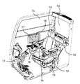
キャブ7は、油圧ショベル1を操作するオペレータが搭乗する内部空間が形成された箱型である。図1及び図2に示すように、キャブ7には、内部空間に搭乗したオペレータがキャブ7の外部を視認するために、前面窓7a、左面窓7b、右面窓7c、及び背面窓7dが設けられている。
The cab 7 is a box shape in which an internal space for an operator who operates the hydraulic excavator 1 is formed. As shown in FIGS. 1 and 2, the cab 7 is provided with a
また、キャブ7の左側面には、オペレータがキャブ7に入退室するための出入口が設けられている。さらに、キャブ7の内部空間には、オペレータが着席するシート10と、シート10に着席したオペレータが操作する操作装置(ステアリング、ペダル、レバー、スイッチなど)が配置されている。
Further, on the left side surface of the cab 7, an entrance / exit for an operator to enter / exit the cab 7 is provided. Further, in the internal space of the cab 7, a
キャブ7に搭乗したオペレータが操作装置を操作することによって、下部走行体2が走行し、上部旋回体3が旋回し、フロント作業機4が動作する。操作装置は、走行操作レバー11と、フロント操作レバー12と、ゲートロックレバー(ロック操作部)13と、プッシュボタン14と、キースイッチ15(図3参照)とを含む。ゲートロックレバー13、プッシュボタン14、及びキースイッチ15は、油圧ショベル1の状態を検出する状態検出部の一例である。
When the operator on the cab 7 operates the operating device, the lower
走行操作レバー11は、一対の無限軌道9の回転速度及び回転方向を制御する。すなわち、オペレータが走行操作レバー11を操作することによって、下部走行体2が前進、後退、旋回する。フロント操作レバー12は、油圧シリンダ4d~4fの伸縮を制御する。すなわち、オペレータがフロント操作レバー12を操作することによって、フロント作業機4が動作する。
The traveling operation lever 11 controls the rotation speed and the rotation direction of the pair of
ゲートロックレバー13は、油圧ショベル1(すなわち、走行モータ、旋回モータ、油圧シリンダ4d~4f)の動作を規制するロック状態と、油圧ショベル1の動作を許容する非ロック状態とに切り換え可能に構成されている。ゲートロックレバー13は、例えば、非ロック状態のときに、コントローラ20に操作信号を出力する。
The
すなわち、ゲートロックレバー13から操作信号が出力されていないとき、走行操作レバー11及びフロント操作レバー12をオペレータが操作しても、油圧ショベル1は動作しない。一方、ゲートロックレバー13から操作信号が出力されているとき、オペレータによる走行操作レバー11及びフロント操作レバー12の操作に従って、油圧ショベル1が動作する。
That is, when the operation signal is not output from the
ゲートロックレバー13は、例えば、キャブ7の出入口とシート10との間に配置される。そして、ゲートロックレバー13は、図2の位置まで引き下げると非ロック状態になる。このとき、ゲートロックレバー13は、キャブ7の出入口とシート10との間の通路に張り出して、オペレータのキャブ7への乗降を妨げる。一方、ゲートロックレバー13は、図2の位置から引き上げるとロック状態になる。このとき、ゲートロックレバー13は、キャブ7の出入口とシート10との間の通路から退避して、オペレータのキャブ7への乗降を妨げない。
The
プッシュボタン14は、オペレータによって押下(操作)されている間だけON状態となり、オペレータが押下をやめるとOFF状態になるモーメンタリスイッチである。そして、プッシュボタン14は、例えば、ON状態のときだけコントローラ20に操作信号を出力する。本実施形態では、フロント操作レバー12の先端にプッシュボタン14を設けたが、プッシュボタン14の設置位置はこれに限定されない。
The
キースイッチ15は、エンジンを始動及び停止させるスイッチである。例えば、キースイッチ15にキーを差し込んで第1位置まで回転させると、オルタネータが回転してエンジンが始動する(ON状態)。一方、キーを第2方向まで回転させると、エンジンが停止する(OFF状態)。なお、キースイッチ15は、ゲートロックレバーがロック状態でないと、キーを第1位置まで回転させることができないように構成されていてもよい。
The
また、キースイッチ15は、ON状態のときに、バッテリー8に蓄電された電力を投射装置16及びコントローラ20に供給する。一方、キースイッチ15は、OFF状態のときに、投射装置16及びコントローラ20に電力を供給しない。さらに、キースイッチ15は、エンジンを始動させず、投射装置16及びコントローラ20に電力を供給する第3位置に、キーを回転させることができる構成でもよい(バッテリー駆動状態)。
Further, the
キャブ7の内部空間には、投射装置16と、コンバイナ(表示部)17とが設置されている。投射装置16及びコンバイナ17は、オペレータに報知すべき情報を表示するHUD(Head-Up Display)ユニットを構成する。
A
投射装置16は、コントローラ20の制御に従って、コンバイナ17に画像(静止画像、動画像)を示す画像光を投射する。すなわち、投射装置16は、コンバイナ17に対して所定の角度で入射するように、画像光を投射する。投射装置16の具体的な構成は既に公知なので、詳細な説明は省略する。
The
コンバイナ17は、透明な板状(膜状)の部材であって、キャブ7の窓に貼付される。本実施形態に係るコンバイナ17は、右面窓7cの一部に貼付されている。但し、コンバイナ17の設置位置はこれに限定されず、前面窓7a、左面窓7b、背面窓7dに設置されてもよい。また、既存の窓ガラスにコンバイナ17を貼付する構成に限定されず、コンバイナ17の機能を持った窓ガラスをキャブ7に取り付けてもよい。すなわち、表示部は、窓ガラスであってもよい。
The
コンバイナ17は、キャブ7の外から右面窓7cに入射する光を透過し、且つ投射装置16によって投射される画像光をシート10に着席したオペレータの目の位置に反射する、所謂「ハーフミラー」である。すなわち、シート10に着席したオペレータは、コンバイナ17を通してキャブ7の外を視認することができると共に、投射装置16から投射された画像光で示される画像がコンバイナ17に表示されているように見える。
The
また、上記構成のHUDユニットは、シート10に着席したオペレータに虚像を視認させる。そのため、HUDユニットは、コンバイナ17に表示させる画像の視認距離を、無限遠に設定することができる。すなわち、シート10に着席したオペレータは、油圧ショベル1の周囲の状況と、コンバイナ17に表示された画像とを、焦点距離を大きく変更することなく視認することができる。
Further, the HUD unit having the above configuration makes the operator seated in the
本実施形態に係るHUDユニットは、例えば、油圧ショベル1を操作するオペレータに報知すべき注意事項18を表示する。典型的には、注意事項18は、油圧ショベル1の操作を開始する前に、オペレータに認識させるべき事項である。注意事項18の具体例としては、例えば、不意に上部旋回体3の旋回を開始すると、周囲の人を巻き込む可能性があることを示す画像(図5参照)が該当する。
The HUD unit according to the present embodiment displays, for example, the
但し、コンバイナ17に表示する注意事項18の具体例はこれに限定されず、シートベルトを着用すべきこと、開放した前面窓7aが落ちてくる可能性があること、傾斜地では油圧ショベル1が転倒する可能性があること、フロント作業機4が電線に触れると感電する可能性があること等、様々な注意事項を表示することができる。
However, the specific example of the
さらに、キャブ7の内部には、デカール19が貼付されている。デカール19は、コンバイナ17に表示する注意事項18と同じ内容を含む。本実施形態に係るデカール19は、シート10の後方で且つ背面窓7dの下方の壁に貼付されている。デカール19の貼付位置はこれに限定されないが、オペレータの視界を妨げない位置(例えば、窓7a~7d以外の位置)に貼付するのが望ましい。
Further, a
図3は、油圧ショベル1のブロック図である。油圧ショベル1は、HUDユニットを制御するコントローラ20を備える。より詳細には、コントローラ20は、ゲートロックレバー13、プッシュボタン14、及びキースイッチ15の状態に応じて、コンバイナ17における注意事項18の表示態様が変化するように、投射装置16を制御する。
FIG. 3 is a block diagram of the hydraulic excavator 1. The hydraulic excavator 1 includes a
コントローラ20は、CPU(Central Processing Unit)21、ROM(Read Only Memory)22、及びRAM(Random Access Memory)23を備える。コントローラ20は、ROM22に格納されたプログラムコードをCPU21が読み出して実行することによって、後述する処理を実現する。RAM23は、CPU21がプログラムを実行する際のワークエリアとして用いられる。
The
但し、コントローラ20の具体的な構成はこれに限定されず、ASIC(Application Specific Integrated Circuit)、FPGA(Field-Programmable Gate Array)などのハードウェアによって実現されてもよい。
However, the specific configuration of the
次に、図4を参照して、コントローラ20の動作を説明する。図4は、油圧ショベル1の状態と、注意事項18の表示ステータスとの関係を示す状態遷移図である。
Next, the operation of the
まず、キースイッチ15がOFF状態のとき、バッテリー8から投射装置16及びコントローラ20に電力が供給されない。そのため、コントローラ20は、コンバイナ17に注意事項18を表示しない(表示ステータスA)。また、キースイッチ15がOFF状態のときは、オペレータがゲートロックレバー13及びプッシュボタン14を操作しても、注意事項18は非表示のままである(表示態様が変化しない)。
First, when the
次に、コントローラ20は、ゲートロックレバー13がロック状態で、且つプッシュボタン14がOFF状態のときに、キースイッチ15がOFF状態からON状態に切り換えられると(S11)、コンバイナ17に注意事項18を表示する(表示ステータスB)。
Next, when the
次に、コントローラ20は、キースイッチ15がON状態で、且つゲートロックレバー13がロック状態のときに、プッシュボタン14がOFF状態からON状態に切り換えられると(S12)、コンバイナ17に表示されていた注意事項18を非表示にする(表示ステータスC)。また、コントローラ20は、キースイッチ15がON状態で、且つゲートロックレバー13がロック状態のときに、プッシュボタン14がON状態からOFF状態に切り換えられると(S13)、コンバイナ17に再び注意事項18を表示する(表示ステータスB)。
Next, the
すなわち、コントローラ20は、キースイッチ15がON状態で、且つゲートロックレバー13がロック状態のときに、プッシュボタン14が押下されていない間は注意事項18を表示し、プッシュボタン14が押下されている間は注意事項18を非表示にする。換言すれば、コントローラ20は、プッシュボタン14が押下されている間だけ、注意事項18を一時的に非表示にする。さらに換言すれば、コントローラ20は、ゲートロックレバー13がロック状態であっても、プッシュボタン14が押下されている場合には、注意事項18を非表示にする。
That is, when the
次に、コントローラ20は、キースイッチ15がON状態で、且つプッシュボタン14がOFF状態のときに、ゲートロックレバー13がロック状態から非ロック状態に切り換えられると(S14)、コンバイナ17に表示されていた注意事項18を非表示にする(表示ステータスD)。また、コントローラ20は、キースイッチ15がON状態で、且つプッシュボタン14がOFF状態のときに、ゲートロックレバー13が非ロック状態からロック状態に切り換えられると(S15)、コンバイナ17に注意事項18を表示する(表示ステータスB)。
Next, the
一方、コントローラ20は、キースイッチ15がON状態で、且つプッシュボタン14がON状態のときに、ゲートロックレバー13がロック状態から非ロック状態に(S16)、或いはロック状態から非ロック状態に切り換えられても(S17)、注意事項18の非表示を継続する(表示ステータスC、D)。
On the other hand, the
また、コントローラ20は、キースイッチ15がON状態で、且つゲートロックレバー13が非ロック状態のときに、プッシュボタン14の状態が切り換えられても、注意事項18の非表示を継続する(表示ステータスC)。すなわち、オペレータは、注意事項18の表示ステータスを、ゲートロックレバー13がロック状態のときにプッシュボタン14によって切換可能で、ゲートロックレバー13が非ロック状態のときにプッシュボタン14によって切換不能である。
Further, the
次に、コントローラ20は、ゲートロックレバー13がロック状態で、且つプッシュボタン14がOFF状態のときに、キースイッチ15がON状態からOFF状態に切り換えられると(S18)、コンバイナ17に表示されていた注意事項18を非表示にする(表示ステータスA)。
Next, the
また、コントローラ20は、ゲートロックレバー13がロック状態で、且つプッシュボタン14がON状態のときに、キースイッチ15がON状態からOFF状態に切り換えられると(S19)、注意事項18の非表示を継続する(表示ステータスA)。同様に、コントローラ20は、ゲートロックレバー13が非ロック状態のときに、キースイッチ15がON状態からOFF状態に切り換えられると(S20)、注意事項18の非表示を継続する(表示ステータスA)。
Further, when the
上記の実施形態によれば、例えば以下の作用効果を奏する。 According to the above embodiment, for example, the following effects are exhibited.
上記の実施形態によれば、ゲートロックレバー13がロック状態のときに、注意事項18が右面窓7cに表示される。これにより、油圧ショベル1の操作を開始する前のオペレータに、注意事項18を適切に報知することができる。また、ゲートロックレバー13が非ロック状態のときに、注意事項18が非表示になる。これにより、オペレータの視界を妨げることがないので、オペレータは周囲の状況を確認しながら油圧ショベル1を安全に操作することができる。
According to the above embodiment, when the
また、上記の実施形態によれば、ゲートロックレバー13がロック状態のときに、プッシュボタン14によって注意事項18の表示及び非表示を切り換えることができる。これにより、オペレータがプッシュボタン14を押下すれば、視界を妨げられることなく、外の状況を確認することができる。
Further, according to the above embodiment, when the
また、上記の実施形態によれば、プッシュボタン14をモーメンタリスイッチとしたことにより、外の状況を確認するためにオペレータがプッシュボタン14を押下した後に、注意事項18が非表示のままになるのを防止できる。但し、プッシュボタン14は、オペレータが押下する度にON状態とOFF状態とが切り換わるオルタネートスイッチであってもよい。
Further, according to the above embodiment, since the
また、投射装置16は、バッテリー8から電力が供給されていないときに、注意事項18を表示することができない。そこで、上記の実施形態のように、コンバイナ17に表示する注意事項18と同じ内容のデカール19を、キャブ7に貼付することによって、キースイッチ15がOFF状態のときでも、オペレータに注意事項18を報知することができる。また、デカール19を窓7a~7d以外の場所に貼付することによって、オペレータの視界を妨げることがない。
Further, the
なお、上記の実施形態では、注意事項18を表示することを第1の表示態様の一例とし、注意事項18を非表示にすることを第2の表示態様の一例とした。しかしながら、第1の表示態様及び第2の表示態様の具体例は、これに限定されない。図5は、注意事項18をコンバイナ17の中央に大きく表示した例を示す図である。図6は、注意事項18をコンバイナ17の端部に小さく表示した例を示す図である。
In the above embodiment, displaying the
第1表示態様の他の例として、図5に示すように、コントローラ20は、表示ステータスBのときに、コンバイナ17の中央に注意事項18を大きく表示してもよい。また、第2の表示態様の他の例として、図6に示すように、コントローラ20は、表示ステータスC、Dのときに、コンバイナ17の端部に注意事項18を小さく表示してもよい。
As another example of the first display mode, as shown in FIG. 5, the
すなわち、第2の表示態様は、注意事項18を非表示にすること、第1の表示態様より小さく表示すること、第1の表示態様における表示位置より窓の端に表示すること、のいずれか1つ或いはこれらの組み合わせであってもよい。さらに他の例として、第2の表示態様は、第1の表示態様より透過率を高く設定すること、第1の表示態様より彩度を低く設定すること、第1の表示態様より明度を高くすること、等であってもよい。すなわち、第2の表示態様は、第1の表示態様よりもオペレータの視界を妨げない表示態様であればよい。
That is, in the second display mode, either the
また、表示ステータスC、Dにおける注意事項18の表示態様は、異なっていてもよい。例えば、コントローラ20は、表示ステータスCのときに注意事項18を図6に示すように表示し、表示ステータスDのときに注意事項18を非表示にしてもよい。
Further, the display mode of the
また、表示ステータスBから表示ステータスC、Dへの切り換えのタイミングは、異なっていてもよい。例えば、コントローラ20は、プッシュボタン14がOFF状態からON状態に切り換えられると(S12)、注意事項18の表示態様を直ちに切り換えてもよい。一方、コントローラ20は、ゲートロックレバー13がロック状態から非ロック状態に切り換えられると(S14)、所定の時間(例えば、5秒)が経過してから注意事項18の表示態様を切り換えてもよい。
Further, the timing of switching from the display status B to the display statuses C and D may be different. For example, the
また、状態検出部の具体例は、ゲートロックレバー13、プッシュボタン14、及びキースイッチ15に限定されない。他の例として、水平面に対する油圧ショベル1の傾斜角度を検出する傾斜角センサ、或いは前面窓7aが開放されていることを検出する前窓センサを、状態検出部としてもよい。
Further, specific examples of the state detection unit are not limited to the
また、コンバイナ17に同時に表示する注意事項18は1つに限定されない。すなわち、コントローラ20は、複数の注意事項18をコンバイナ17に並べて表示してもよい。また、コントローラ20は、状態検出部によって検出される油圧ショベル1の状態に応じて、コンバイナ17に表示する注意事項18を切り換えてもよい。
Further, the
一例として、コントローラ20は、キースイッチ15がOFF状態からON状態に切り換えられた直後に、シートベルトの着用を促す注意事項をコンバイナ17に表示してもよい。また、コントローラ20は、キースイッチ15がON状態に切り換えられてから所定の時間が経過した後に、図5に示す注意事項18をコンバイナ17に表示してもよい。
As an example, the
他の例として、コントローラ20は、傾斜角センサによって検出される傾斜角度が閾値以上のときに、傾斜地では油圧ショベル1が転倒する可能性があることを報知する注意事項をコンバイナ17に表示してもよい。さらに他の例として、コントローラ20は、前窓センサによって前面窓7aが開放されていることが検出されたときに、開放された前面窓7aが落ちてくる可能性があることを報知する注意事項をコンバイナ17に表示してもよい。
As another example, the
また、上記の実施形態では、キースイッチ15がON状態のときにゲートロックレバー13及びプッシュボタン14の操作状態に応じて注意事項18の表示及び非表示を切り換える例を説明したが、キースイッチ15がバッテリー駆動状態のときも、同様の処理を行ってもよい。但し、バッテリー8に蓄電された電力を節約するために、コントローラ20は、キースイッチ115がバッテリー駆動状態のときに投射装置16から投射される画像光の光量を、キースイッチ15がON状態のときより小さくしてもよい。
Further, in the above embodiment, an example in which the display / non-display of the
さらに、作業機械の具体例は油圧ショベル1に限定されず、ダンプトラック、モータグレーダー、ホイールローダー等の作業車両であってもよいし、ポストに固定されて動作する固定式の機械であってもよい。 Further, the specific example of the work machine is not limited to the hydraulic excavator 1, and may be a work vehicle such as a dump truck, a motor grader, or a wheel loader, or may be a fixed machine that is fixed to a post and operates. good.
上述した実施形態は、本発明の説明のための例示であり、本発明の範囲をそれらの実施形態にのみ限定する趣旨ではない。当業者は、本発明の要旨を逸脱することなしに、他の様々な態様で本発明を実施することができる。 The embodiments described above are examples for the purpose of explaining the present invention, and the scope of the present invention is not limited to those embodiments. Those skilled in the art can practice the invention in various other embodiments without departing from the gist of the invention.
1 油圧ショベル(作業機械)
2 下部走行体
3 上部旋回体
4 フロント作業機
4a ブーム
4b アーム
4c バケット
4d,4e,4f 油圧シリンダ
5 旋回フレーム
6 カウンタウェイト
7 キャブ
7a 前面窓
7b 左面窓
7c 右面窓
7d 背面窓
8 バッテリー
9 無限軌道
10 シート
11 走行操作レバー
12 フロント操作レバー
13 ゲートロックレバー(ロック操作部)
14 プッシュボタン
15 キースイッチ
16 投射装置
17 コンバイナ
18 注意事項
19 デカール
20 コントローラ
21 CPU
22 ROM
23 RAM
1 Hydraulic excavator (working machine)
2 Lower running
14
22 ROM
23 RAM
Claims (3)
前記作業機械を操作するオペレータへの注意事項を示す画像光を投射する投射装置と、
前記投射装置によって投射される画像光を表示する表示部と、
前記作業機械の状態を検出する状態検出部と、
前記状態検出部で検出した前記作業機械の状態に応じて、前記表示部における前記注意事項の表示態様が変化するように、前記投射装置を制御するコントローラと、
前記作業機械の動作を規制するロック状態、及び前記作業機械の動作を許容する非ロック状態に、オペレータが切り換え可能なロック操作部とを備え、
前記コントローラは、前記表示部に表示する前記注意事項を、前記ロック操作部が前記非ロック状態のときには、前記ロック操作部が前記ロック状態のときに表示する第1の表示態様よりもオペレータの視界を妨げない第2の表示態様にすることを特徴とする作業機械。 A work machine equipped with a cab on which the operator is boarding.
A projection device that projects image light indicating precautions for the operator who operates the work machine, and
A display unit that displays the image light projected by the projection device, and
A state detection unit that detects the state of the work machine, and
A controller that controls the projection device so that the display mode of the precautions on the display unit changes according to the state of the work machine detected by the state detection unit .
A lock operation unit that can be switched between a locked state that regulates the operation of the work machine and an unlocked state that allows the operation of the work machine is provided.
The controller displays the precautions displayed on the display unit in the operator's view rather than the first display mode displayed when the lock operation unit is in the unlocked state and the lock operation unit is in the locked state. A work machine characterized by having a second display mode that does not interfere with the above.
オペレータによって操作されている間だけON状態となり、オペレータが操作をやめるとOFF状態になるモーメンタリスイッチを備え、
前記コントローラは、前記ロック操作部が前記ロック状態であっても前記モーメンタリスイッチがON状態の場合には、前記表示部に表示する前記注意事項を前記第2の表示態様にすることを特徴とする作業機械。 In the work machine according to claim 1 ,
Equipped with a momentary switch that turns on only while being operated by the operator and turns off when the operator stops operating.
The controller is characterized in that when the momentary switch is in the ON state even when the lock operation unit is in the locked state, the precautions displayed on the display unit are set to the second display mode. Work machine.
前記第2の表示態様は、非表示にすること、前記第1の表示態様より小さく表示すること、前記第1の表示態様における表示位置より窓の端に表示すること、のいずれかであることを特徴とする作業機械。 In the work machine according to claim 1 ,
The second display mode is either to hide, to display smaller than the first display mode, or to display at the edge of the window from the display position in the first display mode. A work machine featuring.
Priority Applications (6)
| Application Number | Priority Date | Filing Date | Title |
|---|---|---|---|
| JP2019042923A JP7012038B2 (en) | 2019-03-08 | 2019-03-08 | Work machine |
| US17/272,692 US11952750B2 (en) | 2019-03-08 | 2019-12-11 | Work machine |
| CN201980055494.4A CN112639216B (en) | 2019-03-08 | 2019-12-11 | Working machine |
| KR1020217004726A KR102494287B1 (en) | 2019-03-08 | 2019-12-11 | work machine |
| EP19918800.4A EP3936671A4 (en) | 2019-03-08 | 2019-12-11 | Work machine |
| PCT/JP2019/048445 WO2020183829A1 (en) | 2019-03-08 | 2019-12-11 | Work machine |
Applications Claiming Priority (1)
| Application Number | Priority Date | Filing Date | Title |
|---|---|---|---|
| JP2019042923A JP7012038B2 (en) | 2019-03-08 | 2019-03-08 | Work machine |
Publications (2)
| Publication Number | Publication Date |
|---|---|
| JP2020143559A JP2020143559A (en) | 2020-09-10 |
| JP7012038B2 true JP7012038B2 (en) | 2022-01-27 |
Family
ID=72355470
Family Applications (1)
| Application Number | Title | Priority Date | Filing Date |
|---|---|---|---|
| JP2019042923A Active JP7012038B2 (en) | 2019-03-08 | 2019-03-08 | Work machine |
Country Status (6)
| Country | Link |
|---|---|
| US (1) | US11952750B2 (en) |
| EP (1) | EP3936671A4 (en) |
| JP (1) | JP7012038B2 (en) |
| KR (1) | KR102494287B1 (en) |
| CN (1) | CN112639216B (en) |
| WO (1) | WO2020183829A1 (en) |
Families Citing this family (1)
| Publication number | Priority date | Publication date | Assignee | Title |
|---|---|---|---|---|
| JP2022124643A (en) * | 2021-02-16 | 2022-08-26 | 株式会社小松製作所 | Display system for work machine |
Citations (3)
| Publication number | Priority date | Publication date | Assignee | Title |
|---|---|---|---|---|
| WO2017043107A1 (en) | 2015-09-10 | 2017-03-16 | 富士フイルム株式会社 | Projection-type display device and projection control method |
| WO2017051655A1 (en) | 2015-09-25 | 2017-03-30 | 富士フイルム株式会社 | Projection type display device and projection control method |
| WO2018116601A1 (en) | 2016-12-21 | 2018-06-28 | 富士フイルム株式会社 | Projection-type display device, control method of projection-type display device, and control program of projection-type display device |
Family Cites Families (13)
| Publication number | Priority date | Publication date | Assignee | Title |
|---|---|---|---|---|
| JP4010255B2 (en) * | 2003-02-07 | 2007-11-21 | コベルコ建機株式会社 | Construction machine control equipment |
| KR100702180B1 (en) * | 2005-08-11 | 2007-04-02 | 볼보 컨스트럭션 이키프먼트 홀딩 스웨덴 에이비 | an operator vibration monitoring system for earth moving machinery with operation cab |
| JP4713600B2 (en) * | 2008-01-25 | 2011-06-29 | 住友建機株式会社 | Display system for construction machinery |
| CN103025965B (en) | 2010-07-28 | 2015-08-12 | 沃尔沃建造设备有限公司 | For the rear window of operating room being fixed on the device on construction machinery |
| JP5841008B2 (en) * | 2012-05-28 | 2016-01-06 | ヤンマー株式会社 | Swivel work vehicle |
| CN102852170A (en) * | 2012-08-27 | 2013-01-02 | 泰州市华骏机械设备制造有限公司 | Excavator with auxiliary video system |
| JP6102628B2 (en) | 2013-08-09 | 2017-03-29 | アイシン・エィ・ダブリュ株式会社 | Head-up display device |
| JP6308923B2 (en) * | 2014-09-18 | 2018-04-11 | 住友建機株式会社 | Construction machinery |
| JP6361986B2 (en) * | 2016-05-30 | 2018-07-25 | マツダ株式会社 | Vehicle display device |
| JP6808377B2 (en) * | 2016-06-27 | 2021-01-06 | 住友建機株式会社 | Excavator display |
| KR101899981B1 (en) * | 2016-12-02 | 2018-09-19 | 엘지전자 주식회사 | Head Up Display for Vehicle |
| JP6630855B2 (en) | 2017-01-10 | 2020-01-15 | 富士フイルム株式会社 | Projection display device, control method of projection display device, control program for projection display device |
| JP7039983B2 (en) * | 2017-12-13 | 2022-03-23 | コベルコ建機株式会社 | Alert device for construction machinery |
-
2019
- 2019-03-08 JP JP2019042923A patent/JP7012038B2/en active Active
- 2019-12-11 WO PCT/JP2019/048445 patent/WO2020183829A1/en active Application Filing
- 2019-12-11 EP EP19918800.4A patent/EP3936671A4/en active Pending
- 2019-12-11 CN CN201980055494.4A patent/CN112639216B/en active Active
- 2019-12-11 US US17/272,692 patent/US11952750B2/en active Active
- 2019-12-11 KR KR1020217004726A patent/KR102494287B1/en active IP Right Grant
Patent Citations (3)
| Publication number | Priority date | Publication date | Assignee | Title |
|---|---|---|---|---|
| WO2017043107A1 (en) | 2015-09-10 | 2017-03-16 | 富士フイルム株式会社 | Projection-type display device and projection control method |
| WO2017051655A1 (en) | 2015-09-25 | 2017-03-30 | 富士フイルム株式会社 | Projection type display device and projection control method |
| WO2018116601A1 (en) | 2016-12-21 | 2018-06-28 | 富士フイルム株式会社 | Projection-type display device, control method of projection-type display device, and control program of projection-type display device |
Also Published As
| Publication number | Publication date |
|---|---|
| EP3936671A1 (en) | 2022-01-12 |
| US20210340732A1 (en) | 2021-11-04 |
| KR20210031743A (en) | 2021-03-22 |
| US11952750B2 (en) | 2024-04-09 |
| WO2020183829A1 (en) | 2020-09-17 |
| CN112639216B (en) | 2022-12-16 |
| KR102494287B1 (en) | 2023-02-06 |
| JP2020143559A (en) | 2020-09-10 |
| CN112639216A (en) | 2021-04-09 |
| EP3936671A4 (en) | 2022-12-07 |
Similar Documents
| Publication | Publication Date | Title |
|---|---|---|
| JP4486274B2 (en) | Opening cover unit for head-up display | |
| CN109070800A (en) | Image display and method for vehicle | |
| JP6886106B2 (en) | Electronic mirror systems, automotive doors and automotive | |
| KR101435659B1 (en) | Blind spot monitoring device | |
| JP2004203126A (en) | Outside monitoring device for vehicle | |
| JP4447186B2 (en) | Construction machinery | |
| JP7012038B2 (en) | Work machine | |
| JP2023054217A (en) | Hydraulic shovel | |
| JP2011189775A (en) | Posterolateral checking apparatus for vehicle | |
| JP4567914B2 (en) | Construction machinery | |
| JPH08216789A (en) | External rearview mirror device for automobile | |
| JP5986042B2 (en) | Construction machine travel warning device | |
| JP6547077B2 (en) | Projection display device, control method for projection display device, control program for projection display device | |
| JP2001140286A (en) | Monitoring camera system of construction equipment | |
| JP2870245B2 (en) | Display device for vehicles | |
| JP6922730B2 (en) | Display system for construction machinery | |
| WO2019021587A1 (en) | Projection display device, method for controlling projection display device, and program of controlling projection display device | |
| KR20030065987A (en) | All direction viewing system on vehicle | |
| WO2019017048A1 (en) | Projection type display device, projection type display device control method, and projection type display device control program | |
| JP2008008122A (en) | Monitor for construction machinery | |
| JP2023104605A (en) | Vehicular display system and vehicular display method | |
| JP2020050252A (en) | Display device and vehicle | |
| JP2020157779A (en) | Projection type display device, control method of projection type display device, control program of projection type display device | |
| JP2004243889A (en) | Head-up display | |
| KR20150110239A (en) | Get in close contact with a vehicle safety device and having a structure that is equipped with a car safety device |
Legal Events
| Date | Code | Title | Description |
|---|---|---|---|
| A621 | Written request for application examination |
Free format text: JAPANESE INTERMEDIATE CODE: A621 Effective date: 20210215 |
|
| A131 | Notification of reasons for refusal |
Free format text: JAPANESE INTERMEDIATE CODE: A131 Effective date: 20210914 |
|
| A521 | Request for written amendment filed |
Free format text: JAPANESE INTERMEDIATE CODE: A523 Effective date: 20211109 |
|
| TRDD | Decision of grant or rejection written | ||
| A01 | Written decision to grant a patent or to grant a registration (utility model) |
Free format text: JAPANESE INTERMEDIATE CODE: A01 Effective date: 20220111 |
|
| A61 | First payment of annual fees (during grant procedure) |
Free format text: JAPANESE INTERMEDIATE CODE: A61 Effective date: 20220117 |
|
| R150 | Certificate of patent or registration of utility model |
Ref document number: 7012038 Country of ref document: JP Free format text: JAPANESE INTERMEDIATE CODE: R150 |