EP2599676B1 - Vehicle motion control device - Google Patents
Vehicle motion control device Download PDFInfo
- Publication number
- EP2599676B1 EP2599676B1 EP11812299.3A EP11812299A EP2599676B1 EP 2599676 B1 EP2599676 B1 EP 2599676B1 EP 11812299 A EP11812299 A EP 11812299A EP 2599676 B1 EP2599676 B1 EP 2599676B1
- Authority
- EP
- European Patent Office
- Prior art keywords
- vehicle
- longitudinal acceleration
- curve
- command value
- curvature
- Prior art date
- Legal status (The legal status is an assumption and is not a legal conclusion. Google has not performed a legal analysis and makes no representation as to the accuracy of the status listed.)
- Active
Links
- 230000001133 acceleration Effects 0.000 claims description 396
- 230000008859 change Effects 0.000 claims description 51
- 238000004891 communication Methods 0.000 claims description 29
- 230000007423 decrease Effects 0.000 claims description 15
- 230000036461 convulsion Effects 0.000 claims description 14
- 238000004364 calculation method Methods 0.000 claims description 10
- 230000014509 gene expression Effects 0.000 description 90
- 238000000034 method Methods 0.000 description 70
- 230000008569 process Effects 0.000 description 34
- 238000010586 diagram Methods 0.000 description 24
- 238000012545 processing Methods 0.000 description 14
- 230000005540 biological transmission Effects 0.000 description 11
- 238000003384 imaging method Methods 0.000 description 11
- 238000013459 approach Methods 0.000 description 10
- 230000007246 mechanism Effects 0.000 description 10
- 238000007792 addition Methods 0.000 description 7
- 238000012937 correction Methods 0.000 description 7
- 230000003247 decreasing effect Effects 0.000 description 6
- 239000000654 additive Substances 0.000 description 5
- 230000000996 additive effect Effects 0.000 description 5
- 230000001413 cellular effect Effects 0.000 description 5
- 238000001914 filtration Methods 0.000 description 5
- 230000006870 function Effects 0.000 description 3
- 230000003213 activating effect Effects 0.000 description 2
- 239000010426 asphalt Substances 0.000 description 2
- 238000007796 conventional method Methods 0.000 description 2
- 238000005259 measurement Methods 0.000 description 2
- 230000004044 response Effects 0.000 description 2
- 101100409044 Chlorobaculum tepidum (strain ATCC 49652 / DSM 12025 / NBRC 103806 / TLS) ppk1 gene Proteins 0.000 description 1
- 230000000694 effects Effects 0.000 description 1
- 239000012530 fluid Substances 0.000 description 1
- 238000003825 pressing Methods 0.000 description 1
- 230000015541 sensory perception of touch Effects 0.000 description 1
Images


Classifications
-
- G—PHYSICS
- G06—COMPUTING; CALCULATING OR COUNTING
- G06F—ELECTRIC DIGITAL DATA PROCESSING
- G06F17/00—Digital computing or data processing equipment or methods, specially adapted for specific functions
-
- B—PERFORMING OPERATIONS; TRANSPORTING
- B60—VEHICLES IN GENERAL
- B60T—VEHICLE BRAKE CONTROL SYSTEMS OR PARTS THEREOF; BRAKE CONTROL SYSTEMS OR PARTS THEREOF, IN GENERAL; ARRANGEMENT OF BRAKING ELEMENTS ON VEHICLES IN GENERAL; PORTABLE DEVICES FOR PREVENTING UNWANTED MOVEMENT OF VEHICLES; VEHICLE MODIFICATIONS TO FACILITATE COOLING OF BRAKES
- B60T7/00—Brake-action initiating means
- B60T7/02—Brake-action initiating means for personal initiation
- B60T7/04—Brake-action initiating means for personal initiation foot actuated
- B60T7/042—Brake-action initiating means for personal initiation foot actuated by electrical means, e.g. using travel or force sensors
-
- B—PERFORMING OPERATIONS; TRANSPORTING
- B60—VEHICLES IN GENERAL
- B60T—VEHICLE BRAKE CONTROL SYSTEMS OR PARTS THEREOF; BRAKE CONTROL SYSTEMS OR PARTS THEREOF, IN GENERAL; ARRANGEMENT OF BRAKING ELEMENTS ON VEHICLES IN GENERAL; PORTABLE DEVICES FOR PREVENTING UNWANTED MOVEMENT OF VEHICLES; VEHICLE MODIFICATIONS TO FACILITATE COOLING OF BRAKES
- B60T7/00—Brake-action initiating means
- B60T7/12—Brake-action initiating means for automatic initiation; for initiation not subject to will of driver or passenger
- B60T7/16—Brake-action initiating means for automatic initiation; for initiation not subject to will of driver or passenger operated by remote control, i.e. initiating means not mounted on vehicle
- B60T7/18—Brake-action initiating means for automatic initiation; for initiation not subject to will of driver or passenger operated by remote control, i.e. initiating means not mounted on vehicle operated by wayside apparatus
-
- B—PERFORMING OPERATIONS; TRANSPORTING
- B60—VEHICLES IN GENERAL
- B60W—CONJOINT CONTROL OF VEHICLE SUB-UNITS OF DIFFERENT TYPE OR DIFFERENT FUNCTION; CONTROL SYSTEMS SPECIALLY ADAPTED FOR HYBRID VEHICLES; ROAD VEHICLE DRIVE CONTROL SYSTEMS FOR PURPOSES NOT RELATED TO THE CONTROL OF A PARTICULAR SUB-UNIT
- B60W30/00—Purposes of road vehicle drive control systems not related to the control of a particular sub-unit, e.g. of systems using conjoint control of vehicle sub-units, or advanced driver assistance systems for ensuring comfort, stability and safety or drive control systems for propelling or retarding the vehicle
- B60W30/02—Control of vehicle driving stability
- B60W30/025—Control of vehicle driving stability related to comfort of drivers or passengers
-
- B—PERFORMING OPERATIONS; TRANSPORTING
- B60—VEHICLES IN GENERAL
- B60W—CONJOINT CONTROL OF VEHICLE SUB-UNITS OF DIFFERENT TYPE OR DIFFERENT FUNCTION; CONTROL SYSTEMS SPECIALLY ADAPTED FOR HYBRID VEHICLES; ROAD VEHICLE DRIVE CONTROL SYSTEMS FOR PURPOSES NOT RELATED TO THE CONTROL OF A PARTICULAR SUB-UNIT
- B60W30/00—Purposes of road vehicle drive control systems not related to the control of a particular sub-unit, e.g. of systems using conjoint control of vehicle sub-units, or advanced driver assistance systems for ensuring comfort, stability and safety or drive control systems for propelling or retarding the vehicle
- B60W30/18—Propelling the vehicle
- B60W30/18009—Propelling the vehicle related to particular drive situations
- B60W30/18145—Cornering
-
- B—PERFORMING OPERATIONS; TRANSPORTING
- B60—VEHICLES IN GENERAL
- B60T—VEHICLE BRAKE CONTROL SYSTEMS OR PARTS THEREOF; BRAKE CONTROL SYSTEMS OR PARTS THEREOF, IN GENERAL; ARRANGEMENT OF BRAKING ELEMENTS ON VEHICLES IN GENERAL; PORTABLE DEVICES FOR PREVENTING UNWANTED MOVEMENT OF VEHICLES; VEHICLE MODIFICATIONS TO FACILITATE COOLING OF BRAKES
- B60T2201/00—Particular use of vehicle brake systems; Special systems using also the brakes; Special software modules within the brake system controller
- B60T2201/16—Curve braking control, e.g. turn control within ABS control algorithm
-
- B—PERFORMING OPERATIONS; TRANSPORTING
- B60—VEHICLES IN GENERAL
- B60T—VEHICLE BRAKE CONTROL SYSTEMS OR PARTS THEREOF; BRAKE CONTROL SYSTEMS OR PARTS THEREOF, IN GENERAL; ARRANGEMENT OF BRAKING ELEMENTS ON VEHICLES IN GENERAL; PORTABLE DEVICES FOR PREVENTING UNWANTED MOVEMENT OF VEHICLES; VEHICLE MODIFICATIONS TO FACILITATE COOLING OF BRAKES
- B60T2210/00—Detection or estimation of road or environment conditions; Detection or estimation of road shapes
- B60T2210/20—Road shapes
- B60T2210/24—Curve radius
-
- B—PERFORMING OPERATIONS; TRANSPORTING
- B60—VEHICLES IN GENERAL
- B60T—VEHICLE BRAKE CONTROL SYSTEMS OR PARTS THEREOF; BRAKE CONTROL SYSTEMS OR PARTS THEREOF, IN GENERAL; ARRANGEMENT OF BRAKING ELEMENTS ON VEHICLES IN GENERAL; PORTABLE DEVICES FOR PREVENTING UNWANTED MOVEMENT OF VEHICLES; VEHICLE MODIFICATIONS TO FACILITATE COOLING OF BRAKES
- B60T2210/00—Detection or estimation of road or environment conditions; Detection or estimation of road shapes
- B60T2210/30—Environment conditions or position therewithin
- B60T2210/36—Global Positioning System [GPS]
-
- B—PERFORMING OPERATIONS; TRANSPORTING
- B60—VEHICLES IN GENERAL
- B60W—CONJOINT CONTROL OF VEHICLE SUB-UNITS OF DIFFERENT TYPE OR DIFFERENT FUNCTION; CONTROL SYSTEMS SPECIALLY ADAPTED FOR HYBRID VEHICLES; ROAD VEHICLE DRIVE CONTROL SYSTEMS FOR PURPOSES NOT RELATED TO THE CONTROL OF A PARTICULAR SUB-UNIT
- B60W2552/00—Input parameters relating to infrastructure
- B60W2552/30—Road curve radius
-
- B—PERFORMING OPERATIONS; TRANSPORTING
- B60—VEHICLES IN GENERAL
- B60W—CONJOINT CONTROL OF VEHICLE SUB-UNITS OF DIFFERENT TYPE OR DIFFERENT FUNCTION; CONTROL SYSTEMS SPECIALLY ADAPTED FOR HYBRID VEHICLES; ROAD VEHICLE DRIVE CONTROL SYSTEMS FOR PURPOSES NOT RELATED TO THE CONTROL OF A PARTICULAR SUB-UNIT
- B60W2556/00—Input parameters relating to data
- B60W2556/45—External transmission of data to or from the vehicle
- B60W2556/50—External transmission of data to or from the vehicle for navigation systems
-
- B—PERFORMING OPERATIONS; TRANSPORTING
- B60—VEHICLES IN GENERAL
- B60W—CONJOINT CONTROL OF VEHICLE SUB-UNITS OF DIFFERENT TYPE OR DIFFERENT FUNCTION; CONTROL SYSTEMS SPECIALLY ADAPTED FOR HYBRID VEHICLES; ROAD VEHICLE DRIVE CONTROL SYSTEMS FOR PURPOSES NOT RELATED TO THE CONTROL OF A PARTICULAR SUB-UNIT
- B60W2720/00—Output or target parameters relating to overall vehicle dynamics
- B60W2720/10—Longitudinal speed
- B60W2720/106—Longitudinal acceleration
-
- B—PERFORMING OPERATIONS; TRANSPORTING
- B60—VEHICLES IN GENERAL
- B60W—CONJOINT CONTROL OF VEHICLE SUB-UNITS OF DIFFERENT TYPE OR DIFFERENT FUNCTION; CONTROL SYSTEMS SPECIALLY ADAPTED FOR HYBRID VEHICLES; ROAD VEHICLE DRIVE CONTROL SYSTEMS FOR PURPOSES NOT RELATED TO THE CONTROL OF A PARTICULAR SUB-UNIT
- B60W50/00—Details of control systems for road vehicle drive control not related to the control of a particular sub-unit, e.g. process diagnostic or vehicle driver interfaces
- B60W50/0097—Predicting future conditions
Definitions
- the present invention relates to a vehicle motion control device for accelerating/decelerating a vehicle to make the vehicle suitably move.
- a target speed of the vehicle during the passage through the curve is set from a curvature of the curve present ahead, as well as from the previously set value of the lateral acceleration, and a necessary negative acceleration is created from the target vehicle speed and an actual speed of the vehicle.
- This method of creating the negative acceleration is effective for suppressing divergence from the road if the vehicle needs to approach a curve in excess of a maximum speed at which the vehicle can negotiate the curve.
- the deceleration will not necessarily match the driver's feeling of slowdown.
- One reason for this mismatch is that although the foregoing negative-acceleration creating method based on the target vehicle speed is effective for defining a total amount of deceleration (an integral value of the negative acceleration) occurring before the approach to the curve, that method does not allow time-varying changes in the negative acceleration to be defined.
- Patent Document 2 and Non-Patent Document 1 propose, as methods of defining time-varying changes in the (positive) acceleration/negative acceleration that matches a driver's feeling of slowdown, methods of creating the (positive) acceleration/negative acceleration based on lateral jerk due to the driver's operations. These methods allow the driver to accelerate/decelerate the vehicle in substantially the same manner as a skilled driver, without setting the time-varying changes in negative acceleration on a curve-by-curve basis.
- a deceleration control apparatus and method for controlling deceleration of a vehicle is described.
- a controller is operable to set a target vehicular speed calculated based on a turning condition of the vehicle and a lateral acceleration limitation value.
- the controller is also operable to apply deceleration to the vehicle based on the actual vehicular speed and the target vehicular speed and to correct the deceleration used when the vehicle is traveling along a detected curve.
- Non-Patent Document 1
- the method of creating the (positive) acceleration/negative acceleration based on lateral jerk is a method that assumes a fact that lateral motion has occurred or is occurring in the vehicle, the method being intended to create the (positive) acceleration/negative acceleration in coordination with the lateral motion.
- the method does not allow the creation of the negative acceleration under a state of no lateral motion being caused to the vehicle, such as before the vehicle approaches a curve or when the vehicle is decelerating on a straight road.
- the present invention has been made with the above circumferences in mind, and an object of the invention is to provide a vehicle motion control device designed so that even under a state of no lateral motion being caused to a vehicle, the device accelerates/decelerates the vehicle while improving a driver's feeling of slowdown.
- Said vehicle motion control device includes curve shape acquisition means for acquiring a shape of a curve present in front of a currently traveling vehicle, vehicle position acquisition means for acquiring a position of the vehicle, and vehicle motion control arithmetic means for computing, on the basis of the shape of the curve and the position of the vehicle, a command value relating to longitudinal acceleration to be caused to the vehicle.
- the vehicle motion control arithmetic means computes a plurality of different negative longitudinal acceleration command values during a time interval from before the vehicle reaches a near end of the curve, until the vehicle has approached the curve and traveled to a site having a constant or maximum curvature of the curve.
- a vehicle motion control device includes curve shape acquisition means for acquiring a shape of a curve present in front of a currently traveling vehicle, vehicle position acquisition means for acquiring a position of the vehicle, and vehicle motion control arithmetic means for computing, on the basis of the shape of the curve and the position of the vehicle, a command value relating to longitudinal acceleration to be caused to the vehicle.
- the vehicle motion control arithmetic means computes a negative longitudinal acceleration command value during a time interval from before the vehicle reaches a near end of the curve, until the vehicle has approached the curve and traveled to a site having a constant or maximum curvature of the curve, and the negative longitudinal acceleration command value acts so that except immediately after a start of slowdown, longitudinal jerk that is a change in longitudinal acceleration with time is increased/decreased during the period from before the vehicle reaches the near end of the curve, until the curve has reached the constant or maximum curvature.
- the present invention provides a vehicle motion control device designed so that even under a state of no lateral motion being caused to a vehicle, the device accelerates/decelerates the vehicle with a good driver's feeling.
- FIG. 1 A conceptual diagram is shown in Fig. 1 that represents how longitudinal acceleration in front of a curve changes in the present invention.
- longitudinal acceleration and longitudinal jerk in a conventional technique are denoted as “a” and “a'”, respectively, and longitudinal acceleration and longitudinal jerk in the present invention, as “b” and “b'”, respectively.
- deceleration of a vehicle in the conventional technique is constant during a period from time A at which the vehicle reaches a site present in front of a curve, to time B at which the vehicle starts to approach the curve.
- time A at which the vehicle reaches a site present in front of a curve
- time B at which the vehicle starts to approach the curve.
- longitudinal acceleration continues to change during a period from the time A to time C at which the curvature of a curve becomes constant, and during this change in longitudinal acceleration, the vehicle changes from a deceleration pattern based upon the curvature of the curve in zone D that is where the curve lies far ahead, to a deceleration pattern depending upon time-varying changes in the curvature of the curve in zone E that is where the vehicle position is near the curve.
- the present invention is characterized in that in zone F from a starting point of deceleration to a section at which negative acceleration becomes a maximum, increases and decreases in longitudinal jerk occur in zone G that is where the vehicle exists immediately after it has started to decelerate, and in zone H that is where the vehicle changes to the deceleration pattern near the curve.
- This feature allows the vehicle to change from a deceleration pattern based upon a fact that way before the curve, a driver has recognized a "necessity to slow down because of the curve lying ahead", to the deceleration pattern in which, near the curve, the driver recognizes a "necessity to slow down a little more because of the curve being greater in the curvature” in response to the changes in the curvature of the curve and the deceleration varies with the time-varying changes in the curvature of the curve.
- the slowdown matching the driver's feeling can be realized.
- a method of computing a longitudinal acceleration command value based upon the curvature of the curve and a change in the curvature of the curve is described below using Fig. 2 .
- longitudinal acceleration is plus at its acceleration side and minus at its deceleration side
- negative acceleration takes a plus value at its deceleration side.
- a position that represents in simulated form a point which the driver is viewing at this time is set as a forward fixation point in a traveling direction of the vehicle, and a curvature of a curve at this position is expressed as K PP , and a change in the curvature of the curve, as dK PP /dx.
- the forward fixation point here is a point lying on the forward course of the vehicle, at a distance L pp from the vehicle, L pp being a value obtained by integrating a time T pp set for the vehicle speed V in advance.
- the curvature K PP of the curve has a value of at least 0 independently of a direction of the curve, and if the curve has a sufficiently large radius of curvature, the curvature K PP is taken as 0.
- the lateral acceleration G yEST and lateral jerk dG yEST a change in the lateral acceleration with time, that are estimated to occur during the approach will take values given by expressions (1) and (2), respectively.
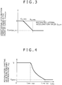
- the longitudinal acceleration command value G xREQfar at this time may be created using, for example, the estimated lateral acceleration value G yEST obtained from above expression (1). More specifically, as shown in Fig.
- the longitudinal acceleration command value G xREQfar may, according to the estimated lateral acceleration value G yEST , be decreased (or increased in terms of negative acceleration) from a set lateral acceleration value G yLMT0 to another set lateral acceleration value G yLMT1 until the longitudinal acceleration command value G xREQfar has been minimized to G yREQfar_min for G yLMT1 .
- the longitudinal acceleration command value G xREQfar may be given by expression (7) using L far as the distance from the vehicle to the forward fixation point far ahead and G ySET as yet another set lateral acceleration value.
- G xREQfar max min c x ⁇ G ySET / ⁇ PP ⁇ V 2 2 ⁇ L far . 0 .
- G xREQfar _ min L far , if it is a value larger than 0, can be a previously set value or a value obtained by integrating the time T pp set for the vehicle speed V in advance.
- G ySET and G xREQfar_min are previously set values, provided that the vehicle motion control device includes means for acquiring road surface friction coefficients and/or means for enabling data setting by the driver, G ySET and G xREQfar_min can be the values that change according to a road surface friction coefficient or the value set by the driver.
- C x can be either a value that is set in advance, or a value that changes in response to, for example, accelerator pedal operations by the driver.
- the method of creating G xREQfar is not limited to or by that of these values, the negative acceleration based on G xREQfar is created so as to be equal to or less than the negative acceleration dictated by the longitudinal acceleration G xREQ in the vicinity of the curve.
- the longitudinal acceleration command values in the vicinity of the curve and at a long distance to the curve are thus obtained.
- Creating a final longitudinal acceleration command value from the obtained command values allows generation of the longitudinal acceleration that increases, as with "b" of Fig. 1 , from the deceleration pattern based on the curvature of the curve way ahead (i.e., in zone D), to the deceleration pattern depending on the change in the curvature of the curve with time in the vicinity of the curve (i.e., in zone E).
- the moving speed V PP of the forward fixation point in expression (6) may be varied in terms of the distance to the curve so as to cause a change from the deceleration pattern in the case that the vehicle position is a long distance off to the curve, to the deceleration pattern in the case that vehicle position is in the vicinity of the curve.
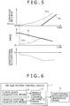
- the moving speed V PP of the forward fixation point may be increased so that: as shown in Fig. 4 , in a region that the forward fixation distance L pp ⁇ is greater than L pp ⁇ _lmt , the moving speed V PP of the forward fixation point equals V PPmin and the vehicle approaches the curve and reaches the vehicle speed V at a forward fixation distance L pp ⁇ _near .
- L pp ⁇ _lmt and L pp ⁇ _near are values that are set in advance to ensure that L pp ⁇ _lmt exceeds L PP ⁇ _near
- V PPmin is a value that is set in advance to exceed 0 but not exceed the vehicle speed V.
- Fig. 4 is a graphical representation of this behavior in a form of the moving speed of the forward fixation point.
- Fig. 6 is a system block diagram showing the configuration of the vehicle motion control device according to the first embodiment of the present invention.
- the vehicle motion control device 1 of the present embodiment intended to be mounted on a vehicle, includes curve shape acquisition means 2 for acquiring a shape of a curve present in front of the vehicle, vehicle position acquisition means 3 for acquiring a position of the vehicle, and vehicle motion control arithmetic means 4 for computing, in accordance with the information that has been obtained by the curve shape acquisition means 2 and the vehicle position acquisition means 3, a longitudinal acceleration to be caused to the vehicle. Computation results by the vehicle motion control arithmetic means 4 are sent to longitudinal acceleration generating means 5 and used to drive an actuator having an ability to cause the longitudinal acceleration to the vehicle.
- the curve shape acquisition means 2 can be or may use any of the following methods: acquiring the shape of the curve from map information relating to a course which the vehicle travels; acquiring curve information on the traveling direction of the vehicle, by means of road-to-vehicle communication; acquiring curve information from a vehicle traveling in front in the traveling direction of the vehicle equipped with the control device, by means of vehicle-to-vehicle communication; acquiring the shape of the curve lying ahead of the vehicle, from imaging means; and acquiring curve shape information by communicating with either map information acquisition means, road-to-vehicle communication means, vehicle-to-vehicle communication means, or the imaging means.
- the vehicle position acquisition means 3 can be, or may use, any of the following methods: acquiring a position of the vehicle relative to the curve in front of the vehicle, from coordinates of the vehicle by means of a global positioning system (GPS); acquiring the position of the vehicle relative to the curve in front of the vehicle, by means of road-to-vehicle communication; acquiring the position of the vehicle relative to the curve in front of the vehicle, by acquiring an image of a scene or object present in front of or around the vehicle, or both thereof, from imaging means; and acquiring the position of the vehicle relative to the curve, by communicating with either the GPS, road-to-vehicle communication means, or the imaging means.
- GPS global positioning system
- the control device may include a plurality of methods as the curve shape acquisition means 2 and the vehicle position acquisition means 3.
- means for acquiring curve shape information from the map information and the imaging means may be provided as the curve shape acquisition means 2
- means for acquiring the vehicle position from the GPS and the imaging means may be provided as the vehicle position acquisition means 3.
- Combination of the plurality of methods allows more accurate curve shape information and vehicle position information to be obtained from, for example, information on surroundings of the curve lying far ahead, and information on the vehicle position.
- the information acquisition may take place by, when the curve is far ahead, using the map information, the GPS-based curve shape information, and the vehicle position information, and when the curve is nearby, using the curve shape information and vehicle position information obtained from the imaging means, in addition to the map information, GPS-based curve shape information, and vehicle position information described above.
- the curve shape information and vehicle position information required for longitudinal acceleration control can be acquired by acquiring the curve shape information and the vehicle position information from the imaging means. Conversely if the curve shape information and the vehicle position information are difficult to acquire with the imaging means, the curve shape information and vehicle position information required for longitudinal acceleration control can be acquired by acquiring the curve shape information and the vehicle position information from the GPS and the map information.
- the longitudinal acceleration generating means 5 is an acceleration/deceleration actuator constructed to generate longitudinal acceleration, the actuator being, for example, either an engine that generates longitudinal acceleration by controlling a throttle angle of the engine, a motor that generates longitudinal acceleration by controlling a driving torque of a motor, a transmission that generates longitudinal acceleration by changing a gear ratio during transmission of motive power to wheels, or a friction brake mechanism that generates longitudinal acceleration by pressing brake discs against brake pads of each wheel.
- the vehicle motion control arithmetic means 4 is an arithmetic unit with a storage region, arithmetic processing capabilities, and signal input/output means.
- the arithmetic means 4 computes, from the curve shape and vehicle position obtained by the curve shape acquisition means 2 and the vehicle position acquisition means 3, respectively, a command value relating to the longitudinal acceleration to be caused to the vehicle, activates the acceleration/deceleration actuator, constructed for generating the longitudinal acceleration that becomes the longitudinal acceleration command value, to work as the longitudinal acceleration generating means 5, and sends the longitudinal acceleration command value to a driving controller of the acceleration/deceleration actuator.
- the command value sent here as a signal is not or does not always need to be the longitudinal acceleration value itself. Instead, the signal needs only to achieve the longitudinal acceleration command value via the acceleration/deceleration actuator.
- the acceleration/deceleration actuator is a hydraulic friction brake mechanism that uses a hydraulic fluid pressure to press a brake pad against a brake disc
- a hydraulic command value for achieving the longitudinal acceleration command value is sent to a hydraulic friction brake controller.
- a driving signal for a hydraulic friction brake driving actuator, created to achieve the longitudinal acceleration command value may be sent directly to the hydraulic friction brake driving actuator, not via the hydraulic friction brake controller.
- acceleration/deceleration actuator used to control driving according to the longitudinal acceleration command value to be achieved may be changed.
- a command value for changing the gear ratio of the transmission may be sent to a transmission controller, and in order to achieve the longitudinal acceleration command value during the slowdown in the vicinity of the curve, the hydraulic command value may be sent to the hydraulic friction brake controller.
- the following describes a method of creating the longitudinal acceleration command value in a case that the curve shape acquisition means 2 uses map information on the course which the vehicle travels, and the vehicle position acquisition means 3 uses a GPS.
- FIG. 7 A flowchart of the computation process in the vehicle motion control device 1 is shown in Fig. 7 .
- step S000 GPS-based vehicle position data P v (X v , Y v ), and node point position data P n (X n , Y n ) that denotes positions of node points present in the traveling direction of the vehicle, as curve shape data from position information on the vehicle and from map information, are acquired and computed.
- "n" is an integer that as shown in Fig. 8 , increases to 1, 2, etc. up to nmax in the traveling direction of the vehicle, with 0 taken as the position of a first node point in a direction opposite to that in which the vehicle is traveling, and nmax is a maximum acquirable value of node point position number "n".
- the process advances to step S100 after the computation.
- step S100 whether the vehicle position data P v (X v , Y v ) has been updated is determined and if the data has been updated, 1 is set up in a data update flag F GPSref , or if the data has not been updated, 0 is set up in the flag.
- the process advances to step S200 after the setup of 1 or 0.
- the determination of whether the data has been updated may be by comparing the vehicle position data P v (X v , Y v ) with its immediately previous setting of P v_z1 (X v_z1 , Y v_z1 ) or by acquiring the update flag, in addition to the vehicle position data, from the GPS.
- step S200 the vehicle speed is calculated from a change in vehicle position with time.
- the setting of the data update flag is 0, an immediately previous vehicle speed calculation result is a current speed of the vehicle.
- the vehicle speed V that is the moving speed of the vehicle is calculated from both of a time ⁇ t p required from a time at which 1 was assigned to the data update flag last time, to a time at which 1 has been assigned to the data update flag this time, and a distance ⁇ L v through which the vehicle has moved.
- the distance ⁇ L v is calculated from both of the vehicle position data P v_Pz1 (X v_Pz1 , Y v_Pz1 ) existing when the presetting of the data update flag was 1, and the vehicle position data P v (X v , Y v ) depending on the current setting of the data update flag.
- step S300 distances to forward fixation points are computed.
- three forward fixation points, PP0, PP1, PP2 from the immediate vicinity of the vehicle to a position far ahead thereof, are set on the course in the traveling direction of the vehicle, and forward fixation distances L PP0 , L PP1 , L PP2 , from the vehicle to the forward fixation points PP0, PP1, PP2 are calculated.
- step S400 computation relating to a longitudinal acceleration control permission flag takes place. If the longitudinal acceleration control permission flag has a value of 1, this indicates that longitudinal acceleration control is permitted, and if the flag has a value of 0, this indicates that longitudinal acceleration control is prohibited.
- the longitudinal acceleration control permission flag is created as follows: for example, if a time during which 0 remains set up in the data update flag F GPSref exceeds a predetermined value, the longitudinal acceleration control permission flag is set to be 0 since GPS-based vehicle position acquisition is regarded as difficult.
- the longitudinal acceleration control permission flag is also set to be 0 since the traveling course of the vehicle on the map data is regarded as different from the actual course.
- the longitudinal acceleration control permission flag may be set to 0 according to the vehicle speed V. For example, a minimum vehicle speed at which control is to be started is set in advance and if the vehicle speed V is lower than the minimum vehicle speed, the longitudinal acceleration control permission flag will be set to 0.
- the longitudinal acceleration control permission flag will be set to 0 if curve shape data and vehicle position data are determined to be difficult to acquire with all of the plurality of acquisition means. For example, during the acquisition of curve shape data and vehicle position data by the imaging means in addition to the GPS, if it is determined that as described above, vehicle position acquisition from the GPS is difficult, and that curve shape data and vehicle position data acquisition by the imaging means is also difficult, then the longitudinal acceleration control permission flag will be set to 0. Under all other conditions, the longitudinal acceleration control permission flag is set to 0. The process advances to step S500 after the computation.
- step S500 the curvatures K n of the curve at each node point position between the point with the node point position data P n (X n , Y n ) and the points with a value of at least 1 of "n", the curvature K v of the curve at the vehicle position, and the changes in the curvature of the curve between the node points, dK n /dx, are calculated and then the curvatures K PP0 , K PP1 , K PP2 of the curve at the forward fixation distances L PP0 , L PP1 , L PP2 , and the changes in the curvature of the curve, dK PP0 /dx, dK PP1 /dx, dK PP2 /dx, are calculated.
- the curvature K n of the curve at node point position P n can be calculated by determining the radii of curvature of the curves of arcs passing through three successive node points, P n-1 , P n , P n+1 , and taking inverse numbers of each.
- the curvature K v of the curve at the vehicle position becomes a curvature K 1 . If the vehicle position disagrees, the curvature K v can be calculated from the node points P 0 , P v , P 1 .
- the curvatures K n and K v here take plus values, irrespective of the direction of the curve.
- the curvature K n may be defined as 0.
- the change in the curvature of the curve, dK n /dx is calculated from the thus-obtained distances between each node point and curvatures K n at each node point.
- the distance between the node points P n , P n+1 is expressed as L n
- the forward fixation point PP0 lies between the vehicle position P v and the node point P 1 , PP1 between P 2 and P 3 , and PP2 between P n and P n+1
- methods of calculating the curvatures of the curve, K n , and changes in the curvature of the curve, dK n /dx, at each node point are not limited to the above and may be those which enable the calculation of the curvatures of the curve as well as changes in the curvature of the curve at each node point.
- the process advances to step S600 after the computations.
- step S600 initial longitudinal acceleration command values are created from the vehicle speed V in addition to the curvatures of the curve, K PP0 , K PP1 , K PP2 , and changes in the curvature of the curve, dK PP0 /dx, dK PP1 /dx, dK PP2 /dx, at the forward fixation distances L PP0 , L PP1 , L PP2 .
- the longitudinal acceleration command values G xREQiniPP0 , G xREQiniPP1 based on the curvatures of the curve, dK PP0 /dx, dK PP1 /dx, in the vicinity of the vehicle, are calculated using expression (6), and the longitudinal acceleration command value G xREQiniPP2 based on the curvature of the curve, K PP2 , far ahead of the vehicle, is created using the method shown in Fig. 3 .
- the forward fixation distances L PP0 , L PP1 , L PP2 here are created using the forward fixation time values T PP0 , T PP1 , T PP2 shown in expression (9), the moving speeds V PP0 , V PP1 , V PP2 of the forward fixation points PP0, PP1, PP2 are given by following expression (18) using the vehicle longitudinal acceleration G x obtained by differentiating the vehicle speed V.
- C xy0 , C xy1 can be values that differ between a case of dK PPm /dx being plus and a case of dK PPm /dx being minus.
- other information such as road surface friction coefficients or the driver's accelerator pedal operations is useable, the above values may each be changed using the information.
- C xy0 , C xy1 are set to be smaller values than for a high road-surface friction coefficient such as that of an asphalt road or equivalent.
- step S700 where the driver is performing accelerator pedal operations, the values that make dK PPm /dx plus are reduced according to a particular operating stroke of the accelerator pedal.
- the configuration that exploits information other than curve shape information and vehicle position information will be described in a second embodiment. After the above computations, the process advances to step S700.
- a final longitudinal acceleration command value G xREQfin is created by providing the initial longitudinal acceleration command values G xREQiniPP0 , G xREQiniPP1 , G xREQiniPP2 , with at least one of a process based on intervention threshold values for longitudinal acceleration control, a filtering process, selective processing, additive processing, and the like. For example, filtering with time constants set up according to a sign and increase/decrease direction of each command value G xREQiniPP0 , G xREQiniPP1 , G xREQiniPP2 , is conducted and then appropriate selective processing and/or additive processing for the particular value follows.
- a longitudinal acceleration control intervention threshold G xBRKs for a decelerating side (braking), and a longitudinal acceleration control intervention threshold G xACCs for an accelerating side are set and these intervention threshold values for longitudinal acceleration control are used for necessary processing.
- the thresholds G xBRKs and G xACCs are values that are set in advance.
- weighting according to the sign may take place. For example, to assign priority to deceleration, a coefficient that reduces a plus value may be integrated for addition. Conversely, to assign priority to acceleration, a coefficient that increases a minus value may be integrated for addition.
- a method of creating G xREQfin from G xREQiniPP0 , G xREQiniPP1 , G xREQiniPP2 in that case is not limited to or by the above description.
- T21 in Fig. 10 there is a change from G xREQiniPP2 to G xREQiniPP1 due to negative longitudinal acceleration, that is, deceleration, the negative acceleration is prevented from decreasing too much.
- step S800 if the setting of the longitudinal acceleration control permission flag is 1, the command value for obtaining the longitudinal acceleration command value G xREQfin , or if the setting of the longitudinal acceleration control permission flag is 0, the command value for prohibiting longitudinal acceleration control is transmitted to the longitudinal acceleration generating means 5.
- the signal transmitted when the setting of the longitudinal acceleration control permission flag is 1 is the longitudinal acceleration command value G xREQfin , which is transmitted as a control command value in the case that as described above, the transmission of the longitudinal acceleration command value G xREQfin allows the longitudinal acceleration generating means 5 to achieve G xREQfin .
- the control command value for the longitudinal acceleration generating means 5, based on the longitudinal acceleration command value G xREQfin is created and transmitted.
- the longitudinal acceleration generating means 5 is the hydraulic friction brake mechanism and this brake mechanism controls the longitudinal acceleration by transmitting a hydraulic command value to the hydraulic friction brake controller, the hydraulic command value based on the longitudinal acceleration command value G xREQfin is created and then the created hydraulic command value is transmitted as the control command value.
- the command for achieving the longitudinal acceleration command value may instead be transmitted to more than one longitudinal acceleration generating means 5.
- the longitudinal acceleration generating means 5 for achieving the longitudinal acceleration that has been created from G xREQiniPP2 a longitudinal acceleration command value obtained a great distance off to the curve, is the transmission, the engine, or both thereof
- the hydraulic friction brake mechanism is added as the longitudinal acceleration generating means 5 for achieving the longitudinal acceleration that has been created from the longitudinal acceleration command values G XREQiniPP1 and G xREQiniPP0 obtained in the vicinity of the curve.
- control device implements substantially the same slowdown as the driver would, upon visually perceiving a curve of a relatively large curvature in far front of the curve in the traveling direction, deactivate the accelerator pedal for a slowdown by engine braking and then after definitely recognizing a change in the curvature of the curve in the vicinity of the curve, operating a brake pedal for a further slowdown.
- the deceleration caused to the vehicle changes the deceleration pattern from the deceleration in far front of the curve to the deceleration in the vicinity of the curve, and this change in deceleration pattern improves the driver's feeling of slowdown without bringing about a need for the driver to excessively slow down before recognizing details of the curve ahead.
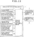
- Fig. 11 is a system block diagram showing the configuration of the vehicle motion control device according to the second embodiment of the present invention.
- the vehicle motion control device 1' of the present embodiment intended to be mounted on a vehicle, includes curve shape acquisition means 2 for acquiring a shape of a curve present in front of the vehicle, vehicle position acquisition means 3 for acquiring a position of the vehicle, vehicle motion information acquisition means 6, driver input information acquisition means 7, lateral motion coordination longitudinal acceleration acquisition means 8, road surface information acquisition means 9, and vehicle motion control arithmetic means 4' for computing a longitudinal acceleration to be caused to the vehicle, the computation being based on the information that has been obtained by the curve shape acquisition means 2 and the vehicle position acquisition means 3, and the information that has been obtained by the vehicle motion information acquisition means 6, the driver input information acquisition means 7, the lateral motion coordination longitudinal acceleration acquisition means 8, and the road surface information acquisition means 9.
- Computation results by the vehicle motion control arithmetic means 4' are sent to longitudinal acceleration generating means 5 and an information presentation unit 10, and used to present information to a driver as well as to drive an actuator having an ability to cause the longitudinal acceleration to the vehicle.
- the curve shape acquisition means 2, vehicle position acquisition means 3 for vehicle information acquisition, and longitudinal acceleration generating means 5 that are included in the above configuration are substantially the same as in the first embodiment, so description of these elements is omitted hereinafter.
- the vehicle motion information acquisition means 6 acquires at least a speed V of the vehicle or a longitudinal acceleration G x , or both thereof, as motion information relating to the vehicle.
- the vehicle speed V and longitudinal acceleration G x acquired here can be either a value directly detected by a sensor, or computation results obtained from an external electronic controller during communication therewith.
- both can be estimated values.
- a wheel speed Vw [wheel] for each of four wheels where [wheel] is filled with characters FL (front left wheel), FR (front right wheel), RL (rear left wheel), or RR (rear right wheel), may be acquired and the vehicle speed V may be estimated from these wheel speeds.
- the driver input information acquisition means 7 acquires at least G xDrvREQ , a longitudinal acceleration requested from the driver, as input information from the driver.
- the driver-requested longitudinal acceleration G xDrvREQ acquired here can be either a value directly entered by the driver, or computation results obtained from the external electronic controller during communication therewith. Even if the driver-requested longitudinal acceleration G xDrvREQ itself is not input, this can be an estimated value.
- an accelerator pedal operating stroke and/or a brake pedal operating stroke may be acquired and the driver-requested longitudinal acceleration G xDrvREQ may be estimated from these stroke values. Otherwise, the driver-requested longitudinal acceleration G xDrvREQ less a negative acceleration by engine braking may be estimated only from an actual operating stroke of the accelerator pedal.
- a torque of the engine and a shift position may be acquired and the driver-requested longitudinal acceleration G xDrvREQ may be estimated from the engine torque and the shift position.
- control ON/OFF information and/or a value adjusted or selected as a control quantity by the driver may be acquired in addition to the driver-requested longitudinal acceleration G xDrvREQ .
- the lateral motion coordination longitudinal acceleration acquisition means 8 acquires a longitudinal acceleration G xGVC based on the lateral jerk of the vehicle, shown in Patent Document 2 or Non-Patent Document 1.
- G xGVC can be an estimated value.
- lateral jerk may be acquired and the longitudinal acceleration G xGVC may be correspondingly computed.
- lateral motion information such as a steering angle, yaw rate, or lateral acceleration, may be acquired and used for computing the longitudinal acceleration G xGVC .
- the road surface information acquisition means 9 acquires at least a road surface friction coefficient ⁇ and a road surface longitudinal gradient Grad, as road surface information.
- both can be estimated values.
- longitudinal acceleration G x each wheel speed Vw [wheel], and/or the vehicle speed V may be acquired and the road surface friction coefficient ⁇ may be estimated from these values.
- a self-aligning torque caused by steering may be acquired as another replacement, and the road surface friction coefficient ⁇ may be estimated from this value.
- a braking/driving force F wx [wheel] of each wheel or information that replaces F wx [wheel] may be acquired as yet another replacement, and the road surface friction coefficient ⁇ may be estimated from these values.
- the road surface longitudinal gradient Grad instead of the road surface longitudinal gradient Grad, the braking/driving force F wx [wheel] of each wheel, information that replaces F wx [wheel] (e.g., the engine torque or the brake pressure), and the longitudinal acceleration G x of the vehicle may be acquired and the road surface longitudinal gradient Grad may be estimated from a difference between a force being caused to the wheel, and an actually developed longitudinal acceleration.
- a value detected by an acceleration sensor mounted to measure a longitudinal acceleration of the vehicle on a flat road may be acquired and the road surface longitudinal gradient Grad may be estimated from a difference between the detected value and a longitudinal acceleration obtained by differentiating the vehicle speed V.
- the vehicle motion control arithmetic means 4' is an arithmetic unit with a storage region, arithmetic processing capabilities, and signal input/output means.
- the vehicle motion control arithmetic means 4' computes the longitudinal acceleration to be caused to the vehicle, and the information to be presented to the driver, and then sends command values to the longitudinal acceleration generating means 5 and the information presentation means 10.
- the command value sent here to the longitudinal acceleration generating means 5 is, as in the first embodiment, a command value matching to the kind of acceleration/deceleration actuator to be driven.
- the information presentation means 10 is a unit that presents the information which the driver can recognize with at least one of five senses, and the command value sent to the information presentation means 10 is that enabling the information presentation unit to be driven.
- the information presentation means 10 is an indicator/display unit, such as an indicator lamp or a display, that gives information to driver's vision
- the command value sent to the indicator/display unit is that which activates the indicator lamp or display necessary information on the display, in accordance with the longitudinal acceleration to be caused to the vehicle.
- the information presentation means 10 is a sound generator, such as a beep sound or voice generator, that gives information to driver's auditory sense
- the command value which provides guidance through a beep sound or voice based on the longitudinal acceleration to be caused to the vehicle, is sent to the sound generator.
- the information presentation means 10 is a vibration generator that gives information to driver's tactile sense by generating some form of vibration, as of a steering wheel, a pedal, or a seat
- the command value sent to the vibration generator is that which makes it generate the vibration on the basis of the longitudinal acceleration to be caused to the vehicle.
- the information presentation means 10 may be a combination of the indicator/display unit, the sound generator, and the vibration generator.
- the following describes a method of creating a longitudinal acceleration command value by acquiring necessary data and information in a case that the curve shape acquisition means 2 uses map information on a course which the vehicle travels, the vehicle position acquisition means 3 uses a GPS, and the vehicle motion information acquisition means 6, the driver input information acquisition means 7, the lateral motion coordination longitudinal acceleration acquisition means 8, and the road surface information acquisition means 9 each use communication means to communicate with an external electronic controller.
- the communication means is used to acquire the vehicle speed V, the longitudinal acceleration G x , the driver-requested longitudinal acceleration G xDrvREQ , the lateral motion coordination longitudinal acceleration G xGVC , the road surface friction coefficient ⁇ and the road surface longitudinal gradient Grad, by communicating with the external electronic controller, and to acquire longitudinal acceleration control switch ON/OFF information F ctrlsw , and a driver-set value G DrvSet , by communicating with the external electronic controller or by using input means such as a switch.
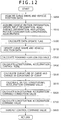
- FIG. 12 A flowchart of a computation process in the vehicle motion control device 1' is shown in Fig. 12 .
- step S000 as in that of the first embodiment, the shape of the curve and position data relating to the vehicle are acquired and computed. The process advances to step S010 after the computation.
- step S010 the vehicle speed V, the longitudinal acceleration G x , the driver-requested longitudinal acceleration G xDrvREQ , the lateral motion coordination longitudinal acceleration G xGVC , the road surface friction coefficient ⁇ , and the road surface longitudinal gradient Grad are acquired.
- the longitudinal acceleration control switch ON/OFF information "F ctrlsw " and the driver-set value G DrvSet are also acquired. Alternatively, if as described above, these values are to be obtained by estimation, not direct acquisition, data necessary for the estimation is acquired and computed. The process advances to step S100 after the computation.
- step S100 as in that of the first embodiment, whether the GPS-based vehicle position data P v (X v , Y v ) has been updated is determined and if the data has been updated, 1 is set up in a data update flag F GPSref , or if the data has not been updated, 0 is set up in the flag.
- the process advances to step S110 after the setup of 1 or 0.
- step S110 the curve shape and vehicle position data that was obtained in step S000 is updated. If the setting of the data update flag which was operated upon in step S100 is 0, that is, if the GPS-based vehicle position data acquired in step S000 is not updated and only the vehicle motion information and other data acquired in step S010 is not updated, the curve shape and vehicle position data will be updated according to a moving distance of the vehicle that is computed from the curve shape and vehicle position data obtained in step S000 and the vehicle speed V obtained from the vehicle motion information.
- the curve shape data obtained at this time will be defined as P t0_n (X t0_n , Y t0_n ) (where "n" is an integer of 0 or larger, but up to nmax_t0) and the vehicle position data will be defined as P t0_v (X t0_v , Y t0_v ).
- a distance between node points P t0_n , P t0_n+1 at this time will be defined as D t0_n+1
- a distance between the vehicle position P t0_v and a node point P t0_1 will be defined as D t0_v1 .
- a first node point in a direction opposite to a traveling direction of the vehicle is set as P 0 .
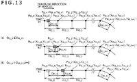
- numbers "n" of each node point change according to a relationship in magnitude between D v and D t0_v1 . If D t1_v is equal to or less than D t0_v1 , then since as shown in Fig.
- step S000 For example, if the vehicle is present between node points P t0_1 , P t0_2 as shown in Fig. 13(b) , then "k" is 1. If the curve shape data obtained in step S000 does not include “k” that satisfies the above conditions, nmax_t0 is taken as "k”. If the setting of the data update flag is 1, the data at each node point that was obtained in step S000, and the corresponding vehicle position data are taken as current curve shape data and vehicle position data, respectively. The process advances to step S310 after the computations.
- step S310 forward fixation distances are computed.
- three forward fixation points, PP0, PP1, PP2, from immediate vicinity of the vehicle to far front thereof, are set on the course in the traveling direction of the vehicle, and forward fixation distances L PP0 , L PP1 , L PP2 , from the vehicle to the forward fixation points PP0, PP1, PP2 are calculated.
- the forward fixation distances L PP0 , L PP1 , L PP2 may each be changed according to the road surface friction coefficient ⁇ . For example, if the road surface friction coefficient ⁇ is less than a certain value, then L PP0 , L PP1 , L PP2 may be changed to be longer as the road surface friction coefficient ⁇ decreases.
- the forward fixation point PP0 is set to be that present in the immediate vicinity of the vehicle, and L max is a value obtained by totaling the distance from the vehicle position to the node point position P 1 , and internode point distances from the node point position P 1 to a maximum node point position P nmax .
- the process advances to step S410 after the computations.
- longitudinal acceleration control mode G xMode is computed.
- the longitudinal acceleration control mode G xMode is a value that is set such that: if the setting is 0, longitudinal acceleration control does not occur; if the setting is 1, longitudinal acceleration control based on the lateral motion coordination longitudinal acceleration G xGVC is conducted; and if the setting is 2, longitudinal acceleration control based on curve shape data as well as on the lateral motion coordination longitudinal acceleration G xGVC and vehicle position data is conducted.
- a method for creating the longitudinal acceleration control mode G xMode is described below. For example, in longitudinal acceleration control switch ON/OFF information F ctrlsw, if 0 is set up in F ctrlsw with the longitudinal acceleration control switch set to OFF and 1 is set up in F ctrlsw with the longitudinal acceleration control switch set to ON, then when F ctrlsw is 0, the setting of the longitudinal acceleration control mode G xMode is also 0.
- the setting of the longitudinal acceleration control mode G xMode may also be 0, depending on the vehicle speed V.
- a minimum vehicle speed at which control is to be started is set beforehand and if the vehicle speed V is lower than the minimum vehicle speed, the longitudinal acceleration control mode G xMode is set to be 0.
- the longitudinal acceleration control mode G xMode is also set to be 0 if the lateral motion coordination longitudinal acceleration G xGVC is difficult to acquire and vehicle position data and curve shape data are also difficult to acquire.
- the longitudinal acceleration control mode G xMode is not under the conditions that it becomes 0, the longitudinal acceleration control mode G xMode is set to be 1 or 2, depending on the curve shape data and the vehicle position data.
- the longitudinal acceleration control mode G xMode is set to be 1 since GPS-based vehicle position acquisition is regarded as difficult.
- the longitudinal acceleration control mode G xMode is also set to be 1, if the D t1_V1 that was computed using expression (27) in step S110 is 0.
- the longitudinal acceleration control mode G xMode is set to be 1, since the traveling course of the vehicle on the map data is regarded as different from the actual course.
- the longitudinal acceleration control mode G xMode When lateral motion information such as a steering angle, yaw rate, or lateral acceleration, can be acquired in addition to the vehicle speed V as vehicle motion, a traveling path estimated from these values, and the GPS-based vehicle position path are computed and if there is a significant departure between the paths, the longitudinal acceleration control mode G xMode is set to be 1, since accuracy of the GPS is recognized as decreasing. Under all other conditions, the longitudinal acceleration control mode G xMode is set to be 2.
- longitudinal acceleration control based on the lateral motion coordination longitudinal acceleration G xGVC can be executed, even under the situation that GPS-based data acquisition is difficult.
- the process advances to step S510 after the computations.
- step S510 if the value of the longitudinal acceleration control mode G xMode is 2, the curvature of the curve and a change in the curvature of the curve are computed as in step S500 of the first embodiment, and if the value of the longitudinal acceleration control mode G xMode is other than 2, the curvature of the curve and the change in the curvature of the curve are both recognized as 0.
- the process advances to step S610 after the computations.
- step S610 initial longitudinal acceleration command values are created from the vehicle speed V in addition to the curvatures of the curve, K PP0 , K PP1 , K PP2 , and changes in the curvature of the curve, dK PP0 /dx, dK PP1 /dx, dK PP2 /dx, at the forward fixation distances L PP0 , L PP1 , L PP2 .
- the longitudinal acceleration command values G xREQiniPP0 , G xREQiniPP1 based on the changes in the curvature of the curve, dK PP0 /dx, dK PP1 /dx, in the vicinity of the vehicle, are calculated using expression (6), and the longitudinal acceleration command value G xREQiniPP2 based on the curvature of the curve, K PP2 , far ahead of the vehicle, is created using expression (7).
- forward fixation distances L PP0 , L PP1 , L PP2 here are created using the forward fixation time values T PP0 , T PP1 , T PP2 shown in expression (9), moving speeds V PP0 , V PP1 , V PP2 of the forward fixation points PP0, PP1, PP2 are given by expression (18) using the vehicle longitudinal acceleration G x . Additionally, the thus-obtained values are next used to compute G xREQiniPP0 , G xREQiniPP1 , in expression (19). Furthermore, G xREQiniPP2 is computed from expression (7). Referring to these expressions, C xy0 , C xy1 , and C x are values that change according to the road surface friction coefficient ⁇ and the driver-requested longitudinal acceleration G xDrvREQ .
- k ⁇ and kG xDrv are values of 0 or more, but up to 1, k ⁇ being set so that in a region of small road-surface friction coefficients ⁇ , the value of k ⁇ is smaller than in a region of large coefficients ⁇ , and kG xDrv being set so that when the driver-requested longitudinal acceleration G xDrvREQ is greater than a certain value, kG xDrv decreases according to an increment in G xDrvREQ and finally becomes 0.
- values of both G ySET and G xREQfar_min in expression (7) change according to the particular road-surface friction coefficient ⁇ . For example, when the road-surface friction coefficient ⁇ is less than a certain value, G ySET and G xREQfar_min are changed to smaller values.
- step S620 As described in the first embodiment, if dK PPm /dx is minus, data that differs from a case in which dK PPm /dx is plus may be set. The process advances to step S620 after the computations.
- G xGrad is a value that becomes minus for an upslope and plus for a downslope. The process advances to step S710 after the computations.
- a final longitudinal acceleration command value G xREQfinGVC is created by providing the longitudinal acceleration command correction values G xREQhoseiPP0 , G xREQhoseiPP1 , G xREQhoseiPP2 , with at least one of a process based on intervention threshold values for longitudinal acceleration control, a filtering process, selective processing, additive processing, and the like, and then further combining the thus-obtained longitudinal acceleration command value G xREQfin with the lateral motion coordination longitudinal acceleration G xGVC .
- G xREQfin The computation of G xREQfin is conducted by computing G xREQhoseiPP0 , G xREQhoseiPP1 , G xREQhoseiPP2 in a manner similar to the computation of G xREQiniPP0 , G xREQiniPP1 , G xREQiniPP2 in step S700 of the first embodiment.
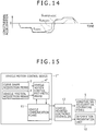
- a method of combining G xREQfin and G xGVC is by, for example as shown in Fig. 14 , if both are of the same sign, adopting the greater of their absolute values as G xREQfinGVC . If both are of different signs, a value obtained by adding both values is adopted as G xREQfinGVC .
- Weighting may be provided during the addition of both values.
- G xREQfinGVC The method of computing G xREQfinGVC by firstly computing G xREQfin and then combining G xREQfin and G xGVC , has been described, but the creation of G xREQfinGVC is not limited to this method.
- G xREQhoseiPP0 which, during the computation of G xREQfin , depends on a position of the forward fixation point PP0 in the immediate vicinity of the vehicle
- G xREQfin is computed using G xGVC , and a value consequently obtained may be used as G xREQfinGVC .
- the process advances to step S810 after the computations.
- step S810 if the longitudinal acceleration control mode is 1 or 2, the command value for obtaining the longitudinal acceleration command value G xREQfinGVC , or if the longitudinal acceleration control mode is 0, the command value for prohibiting longitudinal acceleration control is transmitted to the longitudinal acceleration generating means 5. At the same time, an information presentation command value appropriate for the longitudinal acceleration control state is transmitted to the information presentation unit 10.
- the signal transmitted when the longitudinal acceleration control mode is other than 0 is the longitudinal acceleration command value G xREQfinGVC , which is transmitted as a control command value in the case that as described above, the transmission of the longitudinal acceleration command value G xREQfinGVC allows the longitudinal acceleration generating means 5 to achieve G xREQfinGVC .
- the control command value for the longitudinal acceleration generating means 5, based on the longitudinal acceleration command value G xREQfinGVC is created and transmitted.
- the longitudinal acceleration generating means 5 is the hydraulic friction brake mechanism and this brake mechanism controls the longitudinal acceleration by transmitting a hydraulic command value to the hydraulic friction brake controller
- the hydraulic command value based on the longitudinal acceleration command value G xREQfinGVC is created and then the created hydraulic command value is transmitted as the control command value. This makes the vehicle generate a longitudinal acceleration based on the longitudinal acceleration command value G xREQfinGVC .
- the command for achieving the longitudinal acceleration command value may instead be transmitted to more than one longitudinal acceleration generating means 5.
- the longitudinal acceleration generating means 5 for achieving the longitudinal acceleration that has been created from G xREQhoseiPP2 a longitudinal acceleration command value obtained a great distance off to the curve, is a transmission, the engine, or both thereof
- the hydraulic friction brake mechanism is added as the longitudinal acceleration generating means 5 for achieving the longitudinal acceleration that has been created from the longitudinal acceleration command values G xREQiniPP1 , G xREQiniPP0 , and G xGVC obtained in the vicinity of the curve.
- control device implements substantially the same slowdown as the driver would, upon visually perceiving a curve of a relatively large curvature in far front of the curve in the traveling direction, deactivate the accelerator pedal for a slowdown by engine braking and then after definitely recognizing a change in the curvature of the curve in the vicinity of the curve, operating a brake pedal for a further slowdown.
- the driving command value for the indicator/display unit or sound generator is transmitted to the information presentation unit 10, to notify to the driver that longitudinal acceleration control is underway.
- the longitudinal acceleration control mode is 1, another driving command value for the indicator/display unit or sound generator is transmitted to notify to the driver that the deceleration in front of the curve does not occur, and a reason for this.
- the previous value settings used in the present embodiment may each be changed according to the driver-set value G DrvSet .
- the driver-set value G DrvSet may be defined as taking a value ranging between 0 and 10 inclusive, and a definition may also be conducted so that if the driver-set value G DrvSet is 0, longitudinal acceleration control from the front of the curve, depending on a position of a forward fixation point, does not occur and only longitudinal acceleration control depending on the lateral motion coordination longitudinal acceleration G xGVC takes place.
- T PP0 , T PP1 , T PP2 may all be set to be very small values, and as G DrvSet increases, T PP2 may be set to be large value and G ySET a small value.
- the longitudinal acceleration control matching to the driver's feeling of slowdown can be achieved by using vehicle motion information and road surface information.
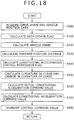
- Fig. 15 is a system block diagram showing the configuration of the vehicle motion control device according to the third embodiment of the present invention.
- the vehicle motion control device 1'' of the present embodiment includes curve shape acquisition means 2 for acquiring a shape of a curve present in front of a vehicle equipped with the control device, vehicle position acquisition means 3 for acquiring a position of the vehicle, vehicle communication means 11 for communicating with an electronic controller 12 mounted on the vehicle, and vehicle motion control arithmetic means 4'' for computing a longitudinal acceleration to be caused to the vehicle, the computation being based on the information that has been obtained by the curve shape acquisition means 2, the vehicle position acquisition means 3, and the vehicle communication means 11.
- Computation results by the vehicle motion control arithmetic means 4'' are sent to longitudinal acceleration generating means 5 and information presentation means 10 via the vehicle-mounted electronic controller 12, and used to drive an actuator having an ability to cause the longitudinal acceleration to the vehicle.
- the vehicle-mounted electronic controller 12 here is means that communicates with the vehicle motion control device 1'', having an ability to drive and control the longitudinal acceleration generating means 5 and the information presentation means 10.
- the vehicle-mounted electronic controller 12 may directly control the driving of the acceleration/deceleration actuator which causes the longitudinal acceleration to the vehicle, or may control the driving of the acceleration/deceleration actuator by communicating with the electronic controller that controls the actuator acceleration/deceleration.
- the controller 12 may either conduct direct driving control of the information presentation unit or conduct driving control of this unit by communicating with the electronic controller that controls the unit.
- the vehicle motion control device 1'' of the present embodiment does not necessarily require mounting on the vehicle and may have a shape allowing a driver to readily remove the device from the vehicle.
- the curve shape acquisition means 2, vehicle position acquisition means 3 for acquiring the vehicle position, longitudinal acceleration generating means 5, and information presentation means 10 here are substantially the same as those of the first and second embodiments, so that detailed description of these elements is omitted herein.
- the vehicle motion control arithmetic means 4'' creates a command value for causing the longitudinal acceleration to the vehicle, in accordance with the information obtained by the curve shape acquisition means 2, the vehicle position acquisition means 3, and the vehicle communication means 11, and communicates with the vehicle-mounted electronic controller 12 via the vehicle communication means 11, thereby controlling the longitudinal acceleration of the vehicle.
- a method of creating the longitudinal acceleration command value in the present embodiment is substantially the same as in the first or second embodiment, so that detailed description of the command-creating method is omitted herein.
- the vehicle communication means 11 is means for communicating with the electronic controller 12 mounted on the vehicle. This means of communication may be, for example, either to interconnect the vehicle motion control device 1'' and the vehicle-mounted electronic controller 12 via a connector and conduct the communication with the vehicle-mounted electronic controller 12, or to register an identification code for the vehicle motion control device 1'', in the vehicle-mounted electronic controller 12 beforehand, and then conduct the communication with the vehicle-mounted electronic controller 12 by wireless communication.
- the vehicle motion control device 1 may, as shown in Fig. 16 , communicate with the longitudinal acceleration generating means 5 and the information presentation means 10 via the vehicle communication means 11 and conduct driving control of the longitudinal acceleration generating means 5 and the information presentation means 10.
- Fig. 17 is a system block diagram showing the configuration of the vehicle motion control device according to the fourth embodiment of the present invention.
- the vehicle motion control device 1''' of the present embodiment includes curve shape acquisition means 2 for acquiring a shape of a curve present in front of a vehicle, vehicle position acquisition means 3 for acquiring a position of the vehicle, vehicle communication means 11 for communicating with an electronic controller 12 mounted on the vehicle, setup information acquisition means 13, and vehicle motion control arithmetic means 4''' for computing a longitudinal acceleration to be caused to the vehicle, the computation being based on the information that has been obtained by the curve shape acquisition means 2, the vehicle position acquisition means 3, the setup information acquisition means 13, and the vehicle communication means 11.
- Computation results by the vehicle motion control arithmetic means 4'' are sent to longitudinal acceleration generating means 5 and information presentation means 10 via the vehicle-mounted electronic controller 12, and used to drive an actuator having an ability to cause the longitudinal acceleration to the vehicle.
- the vehicle motion control device 1''' of the present embodiment does not necessarily require mounting on the vehicle and may have a shape allowing a driver to readily remove the device from the vehicle.
- the curve shape acquisition means 2, vehicle position acquisition means 3 for acquiring the vehicle position, longitudinal acceleration generating means 5, information presentation means 10, vehicle communication means 11, and the vehicle-mounted electronic controller 12 here are substantially the same as those of the first, second, and third embodiments, so that detailed description of these elements is omitted herein.
- the setup information acquisition means 13 acquires the setup information corresponding to selected one of the control modes. For example, the driver can directly enter the forward fixation time values T PP0 , T PP1 , T PP2 and lateral acceleration data settings G ySET in certain ranges and these entered values may be adopted as setup information.
- control modes such as a "sport mode” and a "normal mode" that are determined by combination of several constants may be provided and the constants corresponding to one of the control mode that the driver has selected may be adopted as setup information.
- the vehicle motion control arithmetic means 4"' includes means for storage of the setup information that the setup information acquisition means 13 has acquired.
- the vehicle motion control arithmetic means 4''' creates a command value for causing the longitudinal acceleration to the vehicle, in accordance with the information obtained by the curve shape acquisition means 2, the vehicle position acquisition means 3, the setup information acquisition means 13, and the vehicle communication means 11, and communicates with the vehicle-mounted electronic controller 12 via the vehicle communication means 11, thereby controlling the longitudinal acceleration of the vehicle.
- a method of creating the longitudinal acceleration command value in the present embodiment is substantially the same as in the first and second embodiments, so that detailed description of the command-creating method is omitted herein.
- each driver can implement the driver-set longitudinal acceleration control of the present invention by bringing the cellular phone or compact hand-held navigation unit into the vehicle.
- the configuration of the vehicle motion control device according to the fifth embodiment of the present invention is substantially the same as in the first embodiment.
- the number of forward fixation points used as a reference for computation of a longitudinal acceleration command value differs from that used in the first embodiment.
- FIG. 18 A flowchart of the computation process in the vehicle motion control device 1 is shown in Fig. 18 .
- step S000 as in that of the first embodiment, curve shape data and vehicle position data are acquired and computed.
- step S100 after the computation.
- step S100 as in that of the first embodiment, whether the vehicle position data P v (X v , Y v ) has been updated is determined and if the data has been updated, 1 is set up in a data update flag F GPSref , or if the data has not been updated, 0 is set up in the flag.
- the process advances to step S200 after the setup of 1 or 0.
- step S200 as in that of the first embodiment, the vehicle speed is calculated from a change in vehicle position with time.
- the process advances to step S320 after the calculation.
- step S320 forward fixation distances are computed. As shown in Fig. 19 , two forward fixation points, PP0, PP3, from immediate vicinity of the vehicle to a position far ahead thereof, are set on a course in a traveling direction of the vehicle, and the forward fixation distances L PP0 , L PP3 , from the vehicle to the forward fixation points PP0, PP3 are calculated.
- L PP0 , L PP3 are given by expression (31) using forward fixation time values T PP0 , T PP3 (where T PP0 ⁇ T PP3 ), the vehicle speed V, and moving speeds V PP0 , V PP3 of the forward fixation points, the forward fixation time values T PP0 , T PP3 being set beforehand.
- L PPk min T PPk ⁇ V , L PPk _ z 1 + V PPk ⁇ V ⁇ ⁇ t ⁇ PPk _ z 1 > 0
- K PP0_z1 , K PP3_z1 are immediately previous values of K PP0 , K PP3
- ⁇ t is a unit step time of computation
- “min (A, B)" is a function that specifies A or B, whichever is the smaller.
- the moving speeds V PP0 , V PP3 of the forward fixation points are given by expression (32) using both a vehicle longitudinal acceleration G x obtained by differentiating the vehicle speed V, and moving-speed limiting values V PPlmt0 , V PPlmt3 of the forward fixation points.
- the control device includes means to acquire longitudinal acceleration data by means of either communication with an external controller or direct measurement with an acceleration sensor, the vehicle longitudinal acceleration G x may be created from the longitudinal acceleration data obtained using such methods.
- the moving-speed limiting values V PPlmt0 , V PPlmt3 of the forward fixation points are values that are set beforehand according to the immediately previous values L PP0_z1 , L PP3_z1 of the forward fixation distances.
- the moving-speed limiting values V PPlmt0 , V PPlmt3 may be set so that as shown in Fig.
- time-varying change limiting values dK PPlmto /dt, dK PPlmt3 /dt for the curvatures of the curve at the forward fixation points may be set so that as shown in Fig.
- the values dK PPlmt0 /dt, dK PPlmt3 /dt decrease in a form of a downward convex curve as L PP0_z1 , L PP3_z1 increase; and if the values L PP0_z1 , L PP3_z1 are larger than L PP_lmt , then the values dK PPlmt0 /dt, dK PPlmt3 /dt become equal to 0.
- the moving-speed limiting values V PPlmt0 , V PPlmt3 for the forward fixation points may be given by expression (33) using both dK PPlmt0 /dt, dK PPlmt3 /dt and immediately previous values dK PP0_z1 /dx, dK PP3_z1 /dx of changes in the curvatures of the curve at the forward fixation points.
- V PPk min V + T PPk ⁇ G x , V PPlmtk ⁇ PPk _ z 1 > 0
- V PPImtk d ⁇ PPlmtk / dt d ⁇ PPk _ 1 / dx d ⁇ PP 0 _ z 1 / dx ⁇ 0
- step S400 After the computations, the process advances to step S400.
- step S400 computation relating to a longitudinal acceleration control permission flag takes place similarly to the computation of the longitudinal acceleration control permission flag in the first embodiment.
- the process advances to step S520 after the computation.
- step S520 the curvatures K n of the curve at each of node point positions between a point with node point position data P n (X n , Y n ) and points with a value of at least 1 of "n", the curvature K v of the curve at the vehicle position, and the changes in the curvature of the curve between the node points, dK n /dx, are calculated and then the curvatures K PP0 , K PP3 of the curve at the forward fixation distances L PP0 , L PP3 , and the changes in the curvature of the curve, dK PP0 /dx, dK PP3 /dx, are calculated.
- the curvature K n of the curve at node point position P n can be calculated by determining the radii of curvature of the curves of arcs passing through three successive node points, P n-1 , P n , P n+1 , and taking inverse numbers of each.
- the curvature K n of the curve at each node point and the change in the curvature of the curve, dK n /dx are calculated and after this, the curvatures K PP0 , K PP3 of the curve and changes in the curvature of the curve, dK PP0 /dx, dK PP3 /dx, that correspond to the forward fixation distances L PP0 , L PP3 are calculated. For example, if as shown in Fig.
- the curvature of the curve, K n , and the change in the curvature of the curve, dK n /dx, in these expressions, are not always calculated using the above methods. These values can instead be calculated using any other methods that allow the calculation of the curvature of the curve at each node point and a change in the curvature of the curve thereat.
- the process advances to step S620 after the computations.
- step S620 as shown in expression (4), initial longitudinal acceleration command values are created from the vehicle speed V in addition to the curvatures of the curve and changes in the curvature of the curve with time, at the forward fixation distances L PP0 , L PP3 .
- C xy0 , C xy3 are set to be smaller values than for a high road-surface friction coefficient such as that of an asphalt road or equivalent.
- the values that make dK PPm /dx plus are reduced according to a particular operating stroke of the accelerator pedal.
- the configuration that exploits information other than curve shape information and vehicle position information is as described in the second embodiment. After the above computations, the process advances to step S720.
- a final longitudinal acceleration command value G xREQfin is created by providing the longitudinal acceleration command correction values G xREQiniPP0 , G xREQiniPP3 , with at least one of a process based on intervention threshold values for longitudinal acceleration control, a filtering process, selective processing, additive processing, and the like. For example, filtering with time constants set up according to a sign and increase/decrease direction of each command value G xREQiniPP0 , G xREQiniPP3 , is conducted and then appropriate selective processing and/or additive processing for the particular value follows.
- a longitudinal acceleration control intervention threshold G xBRKs for a decelerating side (braking), and a longitudinal acceleration control intervention threshold G xACCs for an accelerating side are set and these intervention threshold values for longitudinal acceleration control are used for necessary processing.
- the thresholds G xBRKs and G xACCs are values that are set in advance.
- G xREQiniPP0 In a region where G xREQiniPP0 , G xREQiniPP3 simultaneously have a value other than 0, if both are of the same sign, a greater absolute value of either is adopted, or if both are of different signs, a value obtained by adding both is adopted.
- a feeling of the slowdown during traveling a continuous curve improves as a result.
- weighting according to the sign may take place. For example, to assign priority to deceleration, a coefficient that reduces a plus value may be integrated for addition. Conversely, to assign priority to acceleration, a coefficient that decreases a minus value may be integrated for addition.
- step S800 In addition to the increase/decrease in the longitudinal acceleration at that time during the computation of the first negative longitudinal acceleration command value, another increase/decrease in longitudinal acceleration is occurring during a time from a start of an approach to the curve, until the curvature of the curve reaches a maximum value.
- a method of creating G xREQfin from G xREQiniPP0 , G xREQiniPP3 in that case is not limited to or by the above description. However, in a zone that as denoted by T30 in Fig. 22 , there is a change from G xREQiniPP3 to G xREQiniPP0 due to negative longitudinal acceleration, that is, deceleration, the negative acceleration is prevented from decreasing too much. After the computation, the process advances to step S800.
- step S800 as in the first embodiment, if the setting of the longitudinal acceleration control permission flag is 1, the command value for obtaining the longitudinal acceleration command value G xREQfin is transmitted to the longitudinal acceleration generating means 5. On the other hand, if the setting of the longitudinal acceleration control permission flag is 0, the command value for prohibiting longitudinal acceleration control is transmitted to the longitudinal acceleration generating means 5.
- the signal transmitted when the setting of the longitudinal acceleration control permission flag is 1 is the longitudinal acceleration command value G xREQfin , which is transmitted as a control command value in the case that as in the first embodiment, the transmission of the longitudinal acceleration command value G xREQfin allows the longitudinal acceleration generating means 5 to achieve G xREQfin .
- the driver can realize the slowdown that matches the driver's expectations, by increasing negative acceleration in the vicinity of the curve where the driver would begin to recognize time-varying changes in the curvature of the curve in detail. In this case, it is unnecessary for the driver to excessively slow down in far front of the vehicle where the driver is estimated to be unable to recognize the time-varying changes in the curvature of the curve in detail.
- the driver's feeling of the slowdown improves since the slowdown matching the driver's expectations is implemented.
- the fifth embodiment can be implemented in the configuration of any one of the second to fourth embodiments.
Description
- The present invention relates to a vehicle motion control device for accelerating/decelerating a vehicle to make the vehicle suitably move.
- Traditionally, there are known vehicle motion control systems that use the curve information within a car navigation system or a turning lateral acceleration of a vehicle equipped with the motion control system, to slow down the vehicle so that an actual lateral acceleration applied thereto is likely to exceed a previously set value (for example, Patent Document 1).
- In such a control device (system), in order that a magnitude of the lateral acceleration occurring when the vehicle moves past the curve will not exceed the previously set value, a target speed of the vehicle during the passage through the curve is set from a curvature of the curve present ahead, as well as from the previously set value of the lateral acceleration, and a necessary negative acceleration is created from the target vehicle speed and an actual speed of the vehicle. This method of creating the negative acceleration is effective for suppressing divergence from the road if the vehicle needs to approach a curve in excess of a maximum speed at which the vehicle can negotiate the curve.
- However, if the particular setting of the lateral acceleration is a driver-set lateral acceleration that the system is estimated to permit for a usual turn, not a critical lateral acceleration, and the driver executes deceleration control in front of the curve, then the deceleration will not necessarily match the driver's feeling of slowdown. One reason for this mismatch is that although the foregoing negative-acceleration creating method based on the target vehicle speed is effective for defining a total amount of deceleration (an integral value of the negative acceleration) occurring before the approach to the curve, that method does not allow time-varying changes in the negative acceleration to be defined.
- If deceleration control is conducted for constant negative acceleration in front of the curve, the deceleration obtained is likely to mismatch the driver's feeling of slowdown, depending on characteristics of the curve or on the vehicle speed. In addition, if setting the time-varying changes in the negative acceleration is attempted, this requires an unfathomable matching workload and vast volumes of data.
- For example,
Patent Document 2 and Non-PatentDocument 1 propose, as methods of defining time-varying changes in the (positive) acceleration/negative acceleration that matches a driver's feeling of slowdown, methods of creating the (positive) acceleration/negative acceleration based on lateral jerk due to the driver's operations. These methods allow the driver to accelerate/decelerate the vehicle in substantially the same manner as a skilled driver, without setting the time-varying changes in negative acceleration on a curve-by-curve basis. - In
Patent Document 3, a deceleration control apparatus and method for controlling deceleration of a vehicle is described. Thereby, a controller is operable to set a target vehicular speed calculated based on a turning condition of the vehicle and a lateral acceleration limitation value. The controller is also operable to apply deceleration to the vehicle based on the actual vehicular speed and the target vehicular speed and to correct the deceleration used when the vehicle is traveling along a detected curve. -
- Patent Document 1:
JP-2009-51487-A - Patent Document 2:
JP-2008-285066-A - Patent Document 3:
US 2007/106445 A1 - Non-Patent Document 1:
- International Journal of Automotive Engineering (IJAE), Vol. 39, No. 3, 2008
- The method of creating the (positive) acceleration/negative acceleration based on lateral jerk, however, is a method that assumes a fact that lateral motion has occurred or is occurring in the vehicle, the method being intended to create the (positive) acceleration/negative acceleration in coordination with the lateral motion. The method does not allow the creation of the negative acceleration under a state of no lateral motion being caused to the vehicle, such as before the vehicle approaches a curve or when the vehicle is decelerating on a straight road.
- The present invention has been made with the above circumferences in mind, and an object of the invention is to provide a vehicle motion control device designed so that even under a state of no lateral motion being caused to a vehicle, the device accelerates/decelerates the vehicle while improving a driver's feeling of slowdown. Means for Solving the Problems
- The above object is achieved by a vehicle motion control device according to
independent claim 1. Said vehicle motion control device includes curve shape acquisition means for acquiring a shape of a curve present in front of a currently traveling vehicle, vehicle position acquisition means for acquiring a position of the vehicle, and vehicle motion control arithmetic means for computing, on the basis of the shape of the curve and the position of the vehicle, a command value relating to longitudinal acceleration to be caused to the vehicle. If the longitudinal acceleration command value assumes that a direction in which the vehicle is traveling is plus, the vehicle motion control arithmetic means computes a plurality of different negative longitudinal acceleration command values during a time interval from before the vehicle reaches a near end of the curve, until the vehicle has approached the curve and traveled to a site having a constant or maximum curvature of the curve. - A vehicle motion control device according to another aspect of the present invention includes curve shape acquisition means for acquiring a shape of a curve present in front of a currently traveling vehicle, vehicle position acquisition means for acquiring a position of the vehicle, and vehicle motion control arithmetic means for computing, on the basis of the shape of the curve and the position of the vehicle, a command value relating to longitudinal acceleration to be caused to the vehicle. If the longitudinal acceleration command value assumes that a direction in which the vehicle is traveling is plus, the vehicle motion control arithmetic means computes a negative longitudinal acceleration command value during a time interval from before the vehicle reaches a near end of the curve, until the vehicle has approached the curve and traveled to a site having a constant or maximum curvature of the curve, and the negative longitudinal acceleration command value acts so that except immediately after a start of slowdown, longitudinal jerk that is a change in longitudinal acceleration with time is increased/decreased during the period from before the vehicle reaches the near end of the curve, until the curve has reached the constant or maximum curvature.
- The present specification claims priority from the Japanese Patent Application, No.
2010-171304 - The present invention provides a vehicle motion control device designed so that even under a state of no lateral motion being caused to a vehicle, the device accelerates/decelerates the vehicle with a good driver's feeling.
-
-
Fig. 1 is a conceptual diagram that represents how a vehicle motion control device according to the present invention changes a longitudinal acceleration in front of a curve. -
Fig. 2 is a conceptual diagram that represents a relationship in position between a vehicle equipped with the vehicle motion control device according to the present invention, and a driver's forward fixation point. -
Fig. 3 is a diagram that represents a relationship between an estimated lateral acceleration value in the vehicle motion control device according to the present invention, and a longitudinal acceleration command value created at a long distance to the curve. -
Fig. 4 is a diagram that represents a relationship between a distance to the forward fixation point and a moving speed of the forward fixation point, in the vehicle motion control device according to the present invention. -
Fig. 5 is a diagram that represents time-varying changes in the curvature of the curve, speed, and longitudinal acceleration, in the present invention. -
Fig. 6 is a diagram that shows a first embodiment of a vehicle motion control device according to the present invention. -
Fig. 7 is a flowchart of the vehicle motion control device shown inFig. 6 . -
Fig. 8 is a conceptual diagram that shows positions of a vehicle equipped with the vehicle motion control device ofFig. 6 , and positions of node points. -
Fig. 9 is a diagram that represents a relationship between a distance, a curvature of the curve, and changes in the curvature of the curve, in the vehicle motion control device ofFig. 6 . -
Fig. 10 is a diagram that shows the curvature of the curve, changes in the curvature of the curve, and changes in longitudinal acceleration with time, in the vehicle motion control device ofFig. 6 . -
Fig. 11 is a diagram that shows a second embodiment of a vehicle motion control device according to the present invention. -
Fig. 12 is a flowchart of the vehicle motion control device shown inFig. 11 . -
Fig. 13 is a conceptual diagram that shows a relationship between positions of a vehicle equipped with the vehicle motion control device ofFig. 11 , and positions of node points. -
Fig. 14 is a diagram that shows changes in longitudinal acceleration with time, in the vehicle motion control device ofFig. 11 . -
Fig. 15 is a diagram that shows an example of a third embodiment of a vehicle motion control device according to the present invention. -
Fig. 16 is a diagram that shows another example of a third embodiment of a vehicle motion control device according to the present invention. -
Fig. 17 is a diagram that shows a fourth embodiment of a vehicle motion control device according to the present invention. -
Fig. 18 is a flowchart relating to a fifth embodiment of a vehicle motion control device according to the present invention. -
Fig. 19 is a diagram that represents a relationship between a curvature of a curve and changes in the curvature of the curve, in the fifth embodiment of the vehicle motion control device according to the present invention. -
Fig. 20 is a diagram that represents a relationship between a distance to a fifth forward fixation point and a moving speed of the forward fixation point, in the vehicle motion control device according to the present invention. -
Fig. 21 is a diagram that represents a relationship between the distance to the fifth forward fixation point and a maximum change in a curvature of a curve with time at the forward fixation point, in the vehicle motion control device according to the present invention. -
Fig. 22 is a diagram that shows a curvature of a fifth curve, speed, longitudinal acceleration, and changes in the longitudinal acceleration with time, in the vehicle motion control device according to the present invention. - A conceptual diagram is shown in
Fig. 1 that represents how longitudinal acceleration in front of a curve changes in the present invention. - Referring to
Fig. 1 , longitudinal acceleration and longitudinal jerk in a conventional technique are denoted as "a" and "a'", respectively, and longitudinal acceleration and longitudinal jerk in the present invention, as "b" and "b'", respectively. - As shown in
Fig. 1 , deceleration of a vehicle in the conventional technique is constant during a period from time A at which the vehicle reaches a site present in front of a curve, to time B at which the vehicle starts to approach the curve. Under the conditions that makes the vehicle speed high, therefore, strong negative acceleration is likely to occur before a driver of the vehicle definitely recognizes a curvature of the curve, and as a result, even if predetermined lateral acceleration is occurring during a turn, the driver will feel as if the vehicle had slowed down too much in front of the curve. - In the present invention, longitudinal acceleration continues to change during a period from the time A to time C at which the curvature of a curve becomes constant, and during this change in longitudinal acceleration, the vehicle changes from a deceleration pattern based upon the curvature of the curve in zone D that is where the curve lies far ahead, to a deceleration pattern depending upon time-varying changes in the curvature of the curve in zone E that is where the vehicle position is near the curve. Consequently, the present invention is characterized in that in zone F from a starting point of deceleration to a section at which negative acceleration becomes a maximum, increases and decreases in longitudinal jerk occur in zone G that is where the vehicle exists immediately after it has started to decelerate, and in zone H that is where the vehicle changes to the deceleration pattern near the curve.
- This feature allows the vehicle to change from a deceleration pattern based upon a fact that way before the curve, a driver has recognized a "necessity to slow down because of the curve lying ahead", to the deceleration pattern in which, near the curve, the driver recognizes a "necessity to slow down a little more because of the curve being greater in the curvature" in response to the changes in the curvature of the curve and the deceleration varies with the time-varying changes in the curvature of the curve. Briefly, the slowdown matching the driver's feeling can be realized.
- Prior to description of embodiments, for a better understanding of the present invention, a method of computing a longitudinal acceleration command value based upon the curvature of the curve and a change in the curvature of the curve is described below using
Fig. 2 . In the present specification, longitudinal acceleration is plus at its acceleration side and minus at its deceleration side, and negative acceleration takes a plus value at its deceleration side. Consider a scene in which, as shown inFig. 2 , the vehicle travels at a vehicle speed V along a traveling course denoted as a dashed line. At this time, the driver is estimated to look at a shape of the traveling course ahead and accelerate/decelerate the vehicle. A position that represents in simulated form a point which the driver is viewing at this time is set as a forward fixation point in a traveling direction of the vehicle, and a curvature of a curve at this position is expressed as KPP, and a change in the curvature of the curve, as dKPP/dx. The forward fixation point here is a point lying on the forward course of the vehicle, at a distance Lpp from the vehicle, Lpp being a value obtained by integrating a time Tpp set for the vehicle speed V in advance. The curvature KPP of the curve has a value of at least 0 independently of a direction of the curve, and if the curve has a sufficiently large radius of curvature, the curvature KPP is taken as 0. If the vehicle is considered to approach a position of the forward fixation point while maintaining the vehicle speed V, the lateral acceleration GyEST and lateral jerk dGyEST, a change in the lateral acceleration with time, that are estimated to occur during the approach will take values given by expressions (1) and (2), respectively. The lateral acceleration GyEST here, as can be seen from expression (1), will always take a value of at least 0, irrespective of whether the vehicle turns to the left or to the right.
[Expression 1]
[Expression 2]
- Under conditions that the position of the vehicle is near the curve and the distance from the vehicle to the forward fixation point is short, if the driver accelerates/decelerates with substantially the same algorithm as the foregoing methods of creating the (positive) acceleration/negative acceleration based on lateral jerk (
Patent Document 2 and Non-Patent Document 1), the longitudinal acceleration command value GxREQ based upon the estimated lateral jerk value dGyEST will be given by expression (3).
[Expression 3]
where Cxy is a proportionality constant, which is a value that is set in advance. Supposing that an influence of a second term

[Expression 4]
- The longitudinal acceleration command value based upon the time-varying change in the curvature of the curve, dKPP/dt, at the forward fixation point, is thus obtained. Additionally, dKPP/dt can be rewritten as represented by expression (5).
[Expression 5]
where (dx/dt) is a moving speed VPP of the forward fixation point, such that expression (4) is given by expression (6) using VPP.
[Expression 6]
- This allows creation of the longitudinal acceleration command value in vicinity of the curve.
- Conversely, under conditions that the curve is way ahead of the vehicle position and the distance from the vehicle to the forward fixation point is long, the driver is estimated to be decelerating according to an ambiguous curvature of the curve since the driver is probably unable to obtain detailed information such as the change in the curvature of the curve. The longitudinal acceleration command value GxREQfar at this time may be created using, for example, the estimated lateral acceleration value GyEST obtained from above expression (1). More specifically, as shown in
Fig. 3 , the longitudinal acceleration command value GxREQfar may, according to the estimated lateral acceleration value GyEST, be decreased (or increased in terms of negative acceleration) from a set lateral acceleration value GyLMT0 to another set lateral acceleration value GyLMT1 until the longitudinal acceleration command value GxREQfar has been minimized to GyREQfar_min for GyLMT1. Alternatively, the longitudinal acceleration command value GxREQfar may be given by expression (7) using Lfar as the distance from the vehicle to the forward fixation point far ahead and GySET as yet another set lateral acceleration value. Referring to expression (7), "min (A, B)" is a function that specifies A or B, whichever is the smaller, and "max (A, B)" is a function that specifies A or B, whichever is the larger.
[Expression 7]
where Lfar, if it is a value larger than 0, can be a previously set value or a value obtained by integrating the time Tpp set for the vehicle speed V in advance. In addition, even when GySET and GxREQfar_min are previously set values, provided that the vehicle motion control device includes means for acquiring road surface friction coefficients and/or means for enabling data setting by the driver, GySET and GxREQfar_min can be the values that change according to a road surface friction coefficient or the value set by the driver. - Furthermore, Cx can be either a value that is set in advance, or a value that changes in response to, for example, accelerator pedal operations by the driver. Although the method of creating GxREQfar is not limited to or by that of these values, the negative acceleration based on GxREQfar is created so as to be equal to or less than the negative acceleration dictated by the longitudinal acceleration GxREQ in the vicinity of the curve.
- The longitudinal acceleration command values in the vicinity of the curve and at a long distance to the curve are thus obtained. Creating a final longitudinal acceleration command value from the obtained command values allows generation of the longitudinal acceleration that increases, as with "b" of
Fig. 1 , from the deceleration pattern based on the curvature of the curve way ahead (i.e., in zone D), to the deceleration pattern depending on the change in the curvature of the curve with time in the vicinity of the curve (i.e., in zone E). - In the above, an independent longitudinal acceleration command has been created in each of the case that the vehicle position is in the vicinity of the curve, and the case that the vehicle position is a long distance off to the curve. Instead, the moving speed VPP of the forward fixation point in expression (6) may be varied in terms of the distance to the curve so as to cause a change from the deceleration pattern in the case that the vehicle position is a long distance off to the curve, to the deceleration pattern in the case that vehicle position is in the vicinity of the curve. For example, if the curvature KPP of the curve at the forward fixation point becomes equal to or more than a certain value KPPlmt, then as a forward fixation distance Lppκ decreases, the moving speed VPP of the forward fixation point may be increased so that: as shown in
Fig. 4 , in a region that the forward fixation distance Lppκ is greater than Lppκ_lmt, the moving speed VPP of the forward fixation point equals VPPmin and the vehicle approaches the curve and reaches the vehicle speed V at a forward fixation distance Lppκ_near. - In this case, Lppκ_lmt and Lppκ_near are values that are set in advance to ensure that Lppκ_lmt exceeds LPPκ_near, and VPPmin is a value that is set in advance to exceed 0 but not exceed the vehicle speed V.
- Under a state that the vehicle position is at a long distance to the curve and the driver has an ambiguous recognition of the curve, the driver's line of sight moves slowly, and as the vehicle approaches the curve and the driver moves the line of sight along the curve, the moving speed of the line of sight tends to increase.
Fig. 4 is a graphical representation of this behavior in a form of the moving speed of the forward fixation point. - Thus, when the vehicle travels along the course having a curve of a curvature Kv at the vehicle position, the curvature KPP of the curve at the forward fixation point and the moving speed VPP of the forward fixation point change as shown in
Fig. 5 . As a result, as the vehicle approaches the curve, negative acceleration gradually increases from the small negative acceleration at the great distance in front of the curve. - Hereunder, a configuration and operation of a vehicle motion control device according to a first embodiment of the present invention will be described using
Figs. 6 to 10 . - First, the configuration of the vehicle motion control device according to the first embodiment of the present invention is described below using
Fig. 6 . -
Fig. 6 is a system block diagram showing the configuration of the vehicle motion control device according to the first embodiment of the present invention. - The vehicle
motion control device 1 of the present embodiment, intended to be mounted on a vehicle, includes curve shape acquisition means 2 for acquiring a shape of a curve present in front of the vehicle, vehicle position acquisition means 3 for acquiring a position of the vehicle, and vehicle motion controlarithmetic means 4 for computing, in accordance with the information that has been obtained by the curve shape acquisition means 2 and the vehicle position acquisition means 3, a longitudinal acceleration to be caused to the vehicle. Computation results by the vehicle motion controlarithmetic means 4 are sent to longitudinal acceleration generating means 5 and used to drive an actuator having an ability to cause the longitudinal acceleration to the vehicle. - The curve shape acquisition means 2 can be or may use any of the following methods: acquiring the shape of the curve from map information relating to a course which the vehicle travels; acquiring curve information on the traveling direction of the vehicle, by means of road-to-vehicle communication; acquiring curve information from a vehicle traveling in front in the traveling direction of the vehicle equipped with the control device, by means of vehicle-to-vehicle communication; acquiring the shape of the curve lying ahead of the vehicle, from imaging means; and acquiring curve shape information by communicating with either map information acquisition means, road-to-vehicle communication means, vehicle-to-vehicle communication means, or the imaging means.
- The vehicle position acquisition means 3 can be, or may use, any of the following methods: acquiring a position of the vehicle relative to the curve in front of the vehicle, from coordinates of the vehicle by means of a global positioning system (GPS); acquiring the position of the vehicle relative to the curve in front of the vehicle, by means of road-to-vehicle communication; acquiring the position of the vehicle relative to the curve in front of the vehicle, by acquiring an image of a scene or object present in front of or around the vehicle, or both thereof, from imaging means; and acquiring the position of the vehicle relative to the curve, by communicating with either the GPS, road-to-vehicle communication means, or the imaging means.
- Referring to the above, the control device may include a plurality of methods as the curve shape acquisition means 2 and the vehicle position acquisition means 3. For example, means for acquiring curve shape information from the map information and the imaging means, may be provided as the curve shape acquisition means 2, and means for acquiring the vehicle position from the GPS and the imaging means, may be provided as the vehicle position acquisition means 3. Combination of the plurality of methods allows more accurate curve shape information and vehicle position information to be obtained from, for example, information on surroundings of the curve lying far ahead, and information on the vehicle position. More specifically, the information acquisition may take place by, when the curve is far ahead, using the map information, the GPS-based curve shape information, and the vehicle position information, and when the curve is nearby, using the curve shape information and vehicle position information obtained from the imaging means, in addition to the map information, GPS-based curve shape information, and vehicle position information described above.
- If the acquisition of the GPS-based vehicle position information is difficult, the curve shape information and vehicle position information required for longitudinal acceleration control can be acquired by acquiring the curve shape information and the vehicle position information from the imaging means. Conversely if the curve shape information and the vehicle position information are difficult to acquire with the imaging means, the curve shape information and vehicle position information required for longitudinal acceleration control can be acquired by acquiring the curve shape information and the vehicle position information from the GPS and the map information.
- The longitudinal acceleration generating means 5 is an acceleration/deceleration actuator constructed to generate longitudinal acceleration, the actuator being, for example, either an engine that generates longitudinal acceleration by controlling a throttle angle of the engine, a motor that generates longitudinal acceleration by controlling a driving torque of a motor, a transmission that generates longitudinal acceleration by changing a gear ratio during transmission of motive power to wheels, or a friction brake mechanism that generates longitudinal acceleration by pressing brake discs against brake pads of each wheel.
- The vehicle motion control
arithmetic means 4 is an arithmetic unit with a storage region, arithmetic processing capabilities, and signal input/output means. Thearithmetic means 4 computes, from the curve shape and vehicle position obtained by the curve shape acquisition means 2 and the vehicle position acquisition means 3, respectively, a command value relating to the longitudinal acceleration to be caused to the vehicle, activates the acceleration/deceleration actuator, constructed for generating the longitudinal acceleration that becomes the longitudinal acceleration command value, to work as the longitudinal acceleration generating means 5, and sends the longitudinal acceleration command value to a driving controller of the acceleration/deceleration actuator. - The command value sent here as a signal, is not or does not always need to be the longitudinal acceleration value itself. Instead, the signal needs only to achieve the longitudinal acceleration command value via the acceleration/deceleration actuator.
- For example, if the acceleration/deceleration actuator is a hydraulic friction brake mechanism that uses a hydraulic fluid pressure to press a brake pad against a brake disc, a hydraulic command value for achieving the longitudinal acceleration command value is sent to a hydraulic friction brake controller. Otherwise, a driving signal for a hydraulic friction brake driving actuator, created to achieve the longitudinal acceleration command value, may be sent directly to the hydraulic friction brake driving actuator, not via the hydraulic friction brake controller.
- In addition, the kind of acceleration/deceleration actuator used to control driving according to the longitudinal acceleration command value to be achieved may be changed.
- For example, in order to achieve the longitudinal acceleration command value during the slowdown of the vehicle at a long distance in front of the curve, a command value for changing the gear ratio of the transmission may be sent to a transmission controller, and in order to achieve the longitudinal acceleration command value during the slowdown in the vicinity of the curve, the hydraulic command value may be sent to the hydraulic friction brake controller.
- The following describes a method of creating the longitudinal acceleration command value in a case that the curve shape acquisition means 2 uses map information on the course which the vehicle travels, and the vehicle position acquisition means 3 uses a GPS.
- A flowchart of the computation process in the vehicle
motion control device 1 is shown inFig. 7 . - In step S000, GPS-based vehicle position data Pv(Xv, Yv), and node point position data Pn (Xn, Yn) that denotes positions of node points present in the traveling direction of the vehicle, as curve shape data from position information on the vehicle and from map information, are acquired and computed. Referring to the node point position data, "n" is an integer that as shown in
Fig. 8 , increases to 1, 2, etc. up to nmax in the traveling direction of the vehicle, with 0 taken as the position of a first node point in a direction opposite to that in which the vehicle is traveling, and nmax is a maximum acquirable value of node point position number "n". The process advances to step S100 after the computation. - In step S100, whether the vehicle position data Pv(Xv, Yv) has been updated is determined and if the data has been updated, 1 is set up in a data update flag FGPSref, or if the data has not been updated, 0 is set up in the flag. The process advances to step S200 after the setup of 1 or 0. The determination of whether the data has been updated may be by comparing the vehicle position data Pv(Xv, Yv) with its immediately previous setting of Pv_z1 (Xv_z1, Yv_z1) or by acquiring the update flag, in addition to the vehicle position data, from the GPS.
- In step S200, the vehicle speed is calculated from a change in vehicle position with time. At this time, if the setting of the data update flag is 0, an immediately previous vehicle speed calculation result is a current speed of the vehicle. If the setting of the data update flag is 1, the vehicle speed V that is the moving speed of the vehicle is calculated from both of a time Δtp required from a time at which 1 was assigned to the data update flag last time, to a time at which 1 has been assigned to the data update flag this time, and a distance ΔLv through which the vehicle has moved. The distance ΔLv is calculated from both of the vehicle position data Pv_Pz1(Xv_Pz1, Yv_Pz1) existing when the presetting of the data update flag was 1, and the vehicle position data Pv(Xv, Yv) depending on the current setting of the data update flag.
- In step S300, distances to forward fixation points are computed. As shown in
Fig. 9 , three forward fixation points, PP0, PP1, PP2, from the immediate vicinity of the vehicle to a position far ahead thereof, are set on the course in the traveling direction of the vehicle, and forward fixation distances LPP0, LPP1, LPP2, from the vehicle to the forward fixation points PP0, PP1, PP2 are calculated. - In this case, even if values of LPP0, LPP1, LPP2 are set beforehand to satisfy a relationship shown in expression (8) below, forward fixation time values TPP0, TPP1, TPP2 that are set beforehand to satisfy TPP0 < TPP1 < TPP2, and the vehicle speed V may be used to assign each of those distance values so that a relationship shown in expression (9) will hold. These expressions, however, assume that the forward fixation point PP0 is present in the immediate vicinity of the vehicle and that a maximum distance Lmax is a value obtained by totaling the distance from the vehicle position to the node point position P1, and internode point distances from the node point position P1 to a maximum node point position Pnmax. The process advances to step S400 after the computations.
[Expression 8]
[Expression 9]
- In step S400, computation relating to a longitudinal acceleration control permission flag takes place. If the longitudinal acceleration control permission flag has a value of 1, this indicates that longitudinal acceleration control is permitted, and if the flag has a value of 0, this indicates that longitudinal acceleration control is prohibited. The longitudinal acceleration control permission flag is created as follows: for example, if a time during which 0 remains set up in the data update flag FGPSref exceeds a predetermined value, the longitudinal acceleration control permission flag is set to be 0 since GPS-based vehicle position acquisition is regarded as difficult.
- If an actual traveling path based on the vehicle position data significantly departs from the shape of the course on map data that assumes that the vehicle is traveling, the longitudinal acceleration control permission flag is also set to be 0 since the traveling course of the vehicle on the map data is regarded as different from the actual course.
- In addition, the longitudinal acceleration control permission flag may be set to 0 according to the vehicle speed V. For example, a minimum vehicle speed at which control is to be started is set in advance and if the vehicle speed V is lower than the minimum vehicle speed, the longitudinal acceleration control permission flag will be set to 0.
- Furthermore, when the control device is equipped with a plurality of curve shape data acquisition means and vehicle position data acquisition means as described above, the longitudinal acceleration control permission flag will be set to 0 if curve shape data and vehicle position data are determined to be difficult to acquire with all of the plurality of acquisition means. For example, during the acquisition of curve shape data and vehicle position data by the imaging means in addition to the GPS, if it is determined that as described above, vehicle position acquisition from the GPS is difficult, and that curve shape data and vehicle position data acquisition by the imaging means is also difficult, then the longitudinal acceleration control permission flag will be set to 0. Under all other conditions, the longitudinal acceleration control permission flag is set to 0. The process advances to step S500 after the computation.
- In step S500, the curvatures Kn of the curve at each node point position between the point with the node point position data Pn(Xn, Yn) and the points with a value of at least 1 of "n", the curvature Kv of the curve at the vehicle position, and the changes in the curvature of the curve between the node points, dKn/dx, are calculated and then the curvatures KPP0, KPP1, KPP2 of the curve at the forward fixation distances LPP0, LPP1, LPP2, and the changes in the curvature of the curve, dKPP0/dx, dKPP1/dx, dKPP2/dx, are calculated. The curvature Kn of the curve at node point position Pn can be calculated by determining the radii of curvature of the curves of arcs passing through three successive node points, Pn-1, Pn, Pn+1, and taking inverse numbers of each.
- If the vehicle position agrees with the node point position P1, the curvature Kv of the curve at the vehicle position becomes a curvature K1. If the vehicle position disagrees, the curvature Kv can be calculated from the node points P0, Pv, P1. The curvatures Kn and Kv here take plus values, irrespective of the direction of the curve.
- If the radius of curvature of the curve is sufficiently large, the curvature Kn may be defined as 0. The change in the curvature of the curve, dKn/dx, is calculated from the thus-obtained distances between each node point and curvatures Kn at each node point. After internode point linear interpolation, if the distance between the node points Pn, Pn+1 is expressed as Ln, the change in the curvature of the curve, dKn/dx, between the node points Pn, Pn+1, is given as follows by expression (10) :
[Expression 10]
- Likewise, if the distance between the vehicle position Pv and the node point P1 is expressed as Lv1, the change in the curvature of the curve, dKv/dx, between the vehicle position Pv and the node point P1, is given as follows by expression (11):
[Expression 11]
- After the curvatures of the curve, Kn, and changes in the curvature of the curve, dKn/dx, at each node point, have been calculated, the curvatures of the curve, KPP0, KPP1, KPP2, and changes in the curvature of the curve, dKPP0/dx, dKPP1/dx, dKPP2/dx, that correspond to the forward fixation distances LPP0, LPP1, LPP2, are calculated. For example, if as shown in
Fig. 9 , the forward fixation point PP0 lies between the vehicle position Pv and the node point P1, PP1 between P2 and P3, and PP2 between Pn and Pn+1, the curvatures of the curve, KPP0, KPP1, KPP2, and changes in the curvature of the curve, dKPP0/dx, dKPP1/dx, dKPP2/dx, are given as follows by expressions (12) to (17):
[Expression 12]
[Expression 13]
[Expression 14]
[Expression 15]
[Expression 16]
[Expression 17]
- Referring to these expressions, methods of calculating the curvatures of the curve, Kn, and changes in the curvature of the curve, dKn/dx, at each node point, are not limited to the above and may be those which enable the calculation of the curvatures of the curve as well as changes in the curvature of the curve at each node point. The process advances to step S600 after the computations.
- In step S600, initial longitudinal acceleration command values are created from the vehicle speed V in addition to the curvatures of the curve, KPP0, KPP1, KPP2, and changes in the curvature of the curve, dKPP0/dx, dKPP1/dx, dKPP2/dx, at the forward fixation distances LPP0, LPP1, LPP2. The longitudinal acceleration command values GxREQiniPP0, GxREQiniPP1 based on the curvatures of the curve, dKPP0/dx, dKPP1/dx, in the vicinity of the vehicle, are calculated using expression (6), and the longitudinal acceleration command value GxREQiniPP2 based on the curvature of the curve, KPP2, far ahead of the vehicle, is created using the method shown in
Fig. 3 . - If the forward fixation distances LPP0, LPP1, LPP2 here are created using the forward fixation time values TPP0, TPP1, TPP2 shown in expression (9), the moving speeds VPP0, VPP1, VPP2 of the forward fixation points PP0, PP1, PP2 are given by following expression (18) using the vehicle longitudinal acceleration Gx obtained by differentiating the vehicle speed V.
- In a configuration with the means for acquiring longitudinal acceleration by communicating with an external controller or by conducting a direct measurement with the acceleration sensor, the vehicle longitudinal acceleration Gx may be created from the longitudinal acceleration obtained by that acquisition means.
[Expression 18]
- From expressions (6), (18), the longitudinal acceleration command values GxREQiniPP0, GxREQiniPP1 are computed using expression (19). Further, GxREQiniPP2 is computed from
Fig. 3
[Expression 19]
where Cxy0, Cxy1 can each be a constant that is set beforehand, or a value that is changed according to other conditions. For example, Cxy0, Cxy1 can be values that differ between a case of dKPPm/dx being plus and a case of dKPPm/dx being minus. Further alternatively, if other information such as road surface friction coefficients or the driver's accelerator pedal operations is useable, the above values may each be changed using the information. For a low road-surface friction coefficient such as that of a compacted snow road or equivalent, Cxy0, Cxy1 are set to be smaller values than for a high road-surface friction coefficient such as that of an asphalt road or equivalent. - In a further example, where the driver is performing accelerator pedal operations, the values that make dKPPm/dx plus are reduced according to a particular operating stroke of the accelerator pedal. The configuration that exploits information other than curve shape information and vehicle position information will be described in a second embodiment. After the above computations, the process advances to step S700.
- In step S700, a final longitudinal acceleration command value GxREQfin is created by providing the initial longitudinal acceleration command values GxREQiniPP0, GxREQiniPP1, GxREQiniPP2, with at least one of a process based on intervention threshold values for longitudinal acceleration control, a filtering process, selective processing, additive processing, and the like. For example, filtering with time constants set up according to a sign and increase/decrease direction of each command value GxREQiniPP0, GxREQiniPP1, GxREQiniPP2, is conducted and then appropriate selective processing and/or additive processing for the particular value follows.
- Additionally, a longitudinal acceleration control intervention threshold GxBRKs for a decelerating side (braking), and a longitudinal acceleration control intervention threshold GxACCs for an accelerating side are set and these intervention threshold values for longitudinal acceleration control are used for necessary processing. The thresholds GxBRKs and GxACCs are values that are set in advance.
- In a region where two of GxREQiniPP0, GxREQiniPP1, GxREQiniPP2 simultaneously have a value other than 0, if both are of the same sign, a greater absolute value of either is adopted, or if both are of different signs, a value obtained by adding both is adopted. In a region where GxREQiniPP0, GxREQiniPP1, GxREQiniPP2 all simultaneously have a value other than 0, absolute values of two of the same sign, of the three, are compared and a value obtained by adding the greater of the two absolute values and the value of the remaining one having a different sign, is adopted. This reduces the negative acceleration developed in a case that GxREQiniPP0 is plus and GxREQiniPP2 is minus, that is, when there is a curve that generates a minus change in the curvature of the curve at the immediate vicinity of the vehicle and generates a plus change in the curvature of the curve at a position ahead of the vehicle. A feeling of the slowdown during traveling a continuous curve improves as a result.
- During the above additions, weighting according to the sign may take place. For example, to assign priority to deceleration, a coefficient that reduces a plus value may be integrated for addition. Conversely, to assign priority to acceleration, a coefficient that increases a minus value may be integrated for addition.
- Thus, if the vehicle travels a curve that generates those curvatures of the curve, KPP0, KPP1, KPP2, and changes in the curvature of the curve, dKPP0/dx, dKPP1/dx, dKPP2/dx, that are shown in
Fig. 10 , and GxREQiniPP0 shown with a dotted line, GxREQiniPP1 shown with a dashed line, and GxREQiniPP2 shown with a single-dotted line are obtained, then such a longitudinal acceleration command value GxREQfin as shown with a solid line is obtained. A method of creating GxREQfin from GxREQiniPP0, GxREQiniPP1, GxREQiniPP2 in that case is not limited to or by the above description. However, in a zone that as denoted by T21 inFig. 10 , there is a change from GxREQiniPP2 to GxREQiniPP1 due to negative longitudinal acceleration, that is, deceleration, the negative acceleration is prevented from decreasing too much. - Similarly, in a zone that as denoted by T10 in
Fig. 10 , there is a change from GxREQiniPP1 to GxREQiniPP0 due to negative longitudinal acceleration, that is, deceleration, the negative acceleration is prevented from decreasing too much. After the computation, the process advances to step S800. - In step S800, if the setting of the longitudinal acceleration control permission flag is 1, the command value for obtaining the longitudinal acceleration command value GxREQfin, or if the setting of the longitudinal acceleration control permission flag is 0, the command value for prohibiting longitudinal acceleration control is transmitted to the longitudinal acceleration generating means 5.
- The signal transmitted when the setting of the longitudinal acceleration control permission flag is 1 is the longitudinal acceleration command value GxREQfin, which is transmitted as a control command value in the case that as described above, the transmission of the longitudinal acceleration command value GxREQfin allows the longitudinal acceleration generating means 5 to achieve GxREQfin.
- If it is necessary to make the command value match the kind of longitudinal acceleration generating means 5, the control command value for the longitudinal acceleration generating means 5, based on the longitudinal acceleration command value GxREQfin, is created and transmitted. For example, if the longitudinal acceleration generating means 5 is the hydraulic friction brake mechanism and this brake mechanism controls the longitudinal acceleration by transmitting a hydraulic command value to the hydraulic friction brake controller, the hydraulic command value based on the longitudinal acceleration command value GxREQfin is created and then the created hydraulic command value is transmitted as the control command value.
- This makes the vehicle generate a longitudinal acceleration based on the longitudinal acceleration command value GxREQfin.
- The command for achieving the longitudinal acceleration command value may instead be transmitted to more than one longitudinal acceleration generating means 5. For example, if the longitudinal acceleration generating means 5 for achieving the longitudinal acceleration that has been created from GxREQiniPP2, a longitudinal acceleration command value obtained a great distance off to the curve, is the transmission, the engine, or both thereof, the hydraulic friction brake mechanism is added as the longitudinal acceleration generating means 5 for achieving the longitudinal acceleration that has been created from the longitudinal acceleration command values GXREQiniPP1 and GxREQiniPP0 obtained in the vicinity of the curve.
- This generates engine braking force to implement relatively constant slowdown in far front of the curve by changing the throttle angle of the engine or the gear ratio of the transmission, and achieves the deceleration whose rate of change is significant in the vicinity of the curve, by activating the hydraulic friction brake mechanism. Accordingly, the control device implements substantially the same slowdown as the driver would, upon visually perceiving a curve of a relatively large curvature in far front of the curve in the traveling direction, deactivate the accelerator pedal for a slowdown by engine braking and then after definitely recognizing a change in the curvature of the curve in the vicinity of the curve, operating a brake pedal for a further slowdown.
- As described above, in the present invention, the deceleration caused to the vehicle changes the deceleration pattern from the deceleration in far front of the curve to the deceleration in the vicinity of the curve, and this change in deceleration pattern improves the driver's feeling of slowdown without bringing about a need for the driver to excessively slow down before recognizing details of the curve ahead.
- Hereunder, a configuration and operation of a vehicle motion control device according to a second embodiment of the present invention will be described using
Figs. 11 to 14 . - First, the configuration of the vehicle motion control device according to the second embodiment of the present invention is described below using
Fig. 11 . -
Fig. 11 is a system block diagram showing the configuration of the vehicle motion control device according to the second embodiment of the present invention. - The vehicle motion control device 1' of the present embodiment, intended to be mounted on a vehicle, includes curve shape acquisition means 2 for acquiring a shape of a curve present in front of the vehicle, vehicle position acquisition means 3 for acquiring a position of the vehicle, vehicle motion information acquisition means 6, driver input information acquisition means 7, lateral motion coordination longitudinal acceleration acquisition means 8, road surface information acquisition means 9, and vehicle motion control arithmetic means 4' for computing a longitudinal acceleration to be caused to the vehicle, the computation being based on the information that has been obtained by the curve shape acquisition means 2 and the vehicle position acquisition means 3, and the information that has been obtained by the vehicle motion information acquisition means 6, the driver input information acquisition means 7, the lateral motion coordination longitudinal acceleration acquisition means 8, and the road surface information acquisition means 9.
- Computation results by the vehicle motion control arithmetic means 4' are sent to longitudinal acceleration generating means 5 and an
information presentation unit 10, and used to present information to a driver as well as to drive an actuator having an ability to cause the longitudinal acceleration to the vehicle. - The curve shape acquisition means 2, vehicle position acquisition means 3 for vehicle information acquisition, and longitudinal acceleration generating means 5 that are included in the above configuration are substantially the same as in the first embodiment, so description of these elements is omitted hereinafter.
- The vehicle motion information acquisition means 6 acquires at least a speed V of the vehicle or a longitudinal acceleration Gx, or both thereof, as motion information relating to the vehicle. The vehicle speed V and longitudinal acceleration Gx acquired here can be either a value directly detected by a sensor, or computation results obtained from an external electronic controller during communication therewith.
- In addition, even if the vehicle speed V and longitudinal acceleration Gx themselves are not input, both can be estimated values. For example, instead of the vehicle speed V, a wheel speed Vw [wheel] for each of four wheels, where [wheel] is filled with characters FL (front left wheel), FR (front right wheel), RL (rear left wheel), or RR (rear right wheel), may be acquired and the vehicle speed V may be estimated from these wheel speeds.
- The driver input information acquisition means 7 acquires at least GxDrvREQ, a longitudinal acceleration requested from the driver, as input information from the driver. The driver-requested longitudinal acceleration GxDrvREQ acquired here can be either a value directly entered by the driver, or computation results obtained from the external electronic controller during communication therewith. Even if the driver-requested longitudinal acceleration GxDrvREQ itself is not input, this can be an estimated value. For example, instead of the driver-requested longitudinal acceleration GxDrvREQ, an accelerator pedal operating stroke and/or a brake pedal operating stroke may be acquired and the driver-requested longitudinal acceleration GxDrvREQ may be estimated from these stroke values. Otherwise, the driver-requested longitudinal acceleration GxDrvREQ less a negative acceleration by engine braking may be estimated only from an actual operating stroke of the accelerator pedal.
- In a further example, if the vehicle is driven by the engine, a torque of the engine and a shift position may be acquired and the driver-requested longitudinal acceleration GxDrvREQ may be estimated from the engine torque and the shift position. In a further example, control ON/OFF information and/or a value adjusted or selected as a control quantity by the driver may be acquired in addition to the driver-requested longitudinal acceleration GxDrvREQ.
- The lateral motion coordination longitudinal acceleration acquisition means 8 acquires a longitudinal acceleration GxGVC based on the lateral jerk of the vehicle, shown in
Patent Document 2 orNon-Patent Document 1. In this case, even if the longitudinal acceleration GxGVC itself is not input, GxGVC can be an estimated value. For example, instead of the longitudinal acceleration GxGVC, lateral jerk may be acquired and the longitudinal acceleration GxGVC may be correspondingly computed. Alternatively, lateral motion information such as a steering angle, yaw rate, or lateral acceleration, may be acquired and used for computing the longitudinal acceleration GxGVC. - The road surface information acquisition means 9 acquires at least a road surface friction coefficient µ and a road surface longitudinal gradient Grad, as road surface information. In this case, even if the road surface friction coefficient µ and the road surface longitudinal gradient Grad themselves are not input, both can be estimated values. For example, instead of the road surface friction coefficient µ, longitudinal acceleration Gx, each wheel speed Vw [wheel], and/or the vehicle speed V may be acquired and the road surface friction coefficient µ may be estimated from these values. A self-aligning torque caused by steering may be acquired as another replacement, and the road surface friction coefficient µ may be estimated from this value.
- A braking/driving force Fwx [wheel] of each wheel or information that replaces Fwx [wheel] (e.g., a torque of the engine or a brake pressure) may be acquired as yet another replacement, and the road surface friction coefficient µ may be estimated from these values. Further alternatively, instead of the road surface longitudinal gradient Grad, the braking/driving force Fwx [wheel] of each wheel, information that replaces Fwx [wheel] (e.g., the engine torque or the brake pressure), and the longitudinal acceleration Gx of the vehicle may be acquired and the road surface longitudinal gradient Grad may be estimated from a difference between a force being caused to the wheel, and an actually developed longitudinal acceleration. In a further example, a value detected by an acceleration sensor mounted to measure a longitudinal acceleration of the vehicle on a flat road may be acquired and the road surface longitudinal gradient Grad may be estimated from a difference between the detected value and a longitudinal acceleration obtained by differentiating the vehicle speed V.
- The vehicle motion control arithmetic means 4' is an arithmetic unit with a storage region, arithmetic processing capabilities, and signal input/output means. On the basis of the information obtained by the vehicle motion information acquisition means 6, the driver input information acquisition means 7, the lateral motion coordination longitudinal acceleration acquisition means 8, and the road surface information acquisition means 9, as well as by the curve shape acquisition means 2 and the vehicle position acquisition means 3, the vehicle motion control arithmetic means 4' computes the longitudinal acceleration to be caused to the vehicle, and the information to be presented to the driver, and then sends command values to the longitudinal acceleration generating means 5 and the information presentation means 10. The command value sent here to the longitudinal acceleration generating means 5 is, as in the first embodiment, a command value matching to the kind of acceleration/deceleration actuator to be driven.
- The information presentation means 10 is a unit that presents the information which the driver can recognize with at least one of five senses, and the command value sent to the information presentation means 10 is that enabling the information presentation unit to be driven. For example, if the information presentation means 10 is an indicator/display unit, such as an indicator lamp or a display, that gives information to driver's vision, the command value sent to the indicator/display unit is that which activates the indicator lamp or display necessary information on the display, in accordance with the longitudinal acceleration to be caused to the vehicle.
- If the information presentation means 10 is a sound generator, such as a beep sound or voice generator, that gives information to driver's auditory sense, the command value, which provides guidance through a beep sound or voice based on the longitudinal acceleration to be caused to the vehicle, is sent to the sound generator.
- If the information presentation means 10 is a vibration generator that gives information to driver's tactile sense by generating some form of vibration, as of a steering wheel, a pedal, or a seat, the command value sent to the vibration generator is that which makes it generate the vibration on the basis of the longitudinal acceleration to be caused to the vehicle. The information presentation means 10 may be a combination of the indicator/display unit, the sound generator, and the vibration generator.
- The following describes a method of creating a longitudinal acceleration command value by acquiring necessary data and information in a case that the curve shape acquisition means 2 uses map information on a course which the vehicle travels, the vehicle position acquisition means 3 uses a GPS, and the vehicle motion information acquisition means 6, the driver input information acquisition means 7, the lateral motion coordination longitudinal acceleration acquisition means 8, and the road surface information acquisition means 9 each use communication means to communicate with an external electronic controller. The communication means is used to acquire the vehicle speed V, the longitudinal acceleration Gx, the driver-requested longitudinal acceleration GxDrvREQ, the lateral motion coordination longitudinal acceleration GxGVC, the road surface friction coefficient µ and the road surface longitudinal gradient Grad, by communicating with the external electronic controller, and to acquire longitudinal acceleration control switch ON/OFF information Fctrlsw, and a driver-set value GDrvSet, by communicating with the external electronic controller or by using input means such as a switch.
- A flowchart of a computation process in the vehicle motion control device 1' is shown in
Fig. 12 . - In step S000, as in that of the first embodiment, the shape of the curve and position data relating to the vehicle are acquired and computed. The process advances to step S010 after the computation.
- In step S010, the vehicle speed V, the longitudinal acceleration Gx, the driver-requested longitudinal acceleration GxDrvREQ, the lateral motion coordination longitudinal acceleration GxGVC, the road surface friction coefficient µ, and the road surface longitudinal gradient Grad are acquired. The longitudinal acceleration control switch ON/OFF information "Fctrlsw" and the driver-set value GDrvSet are also acquired. Alternatively, if as described above, these values are to be obtained by estimation, not direct acquisition, data necessary for the estimation is acquired and computed. The process advances to step S100 after the computation.
- In step S100, as in that of the first embodiment, whether the GPS-based vehicle position data Pv(Xv, Yv) has been updated is determined and if the data has been updated, 1 is set up in a data update flag FGPSref, or if the data has not been updated, 0 is set up in the flag. The process advances to step S110 after the setup of 1 or 0.
- In step S110, the curve shape and vehicle position data that was obtained in step S000 is updated. If the setting of the data update flag which was operated upon in step S100 is 0, that is, if the GPS-based vehicle position data acquired in step S000 is not updated and only the vehicle motion information and other data acquired in step S010 is not updated, the curve shape and vehicle position data will be updated according to a moving distance of the vehicle that is computed from the curve shape and vehicle position data obtained in step S000 and the vehicle speed V obtained from the vehicle motion information.
- For example, if at a time t0, the setting of the data update flag is 1, that is, data is updated using the GPS, the curve shape data obtained at this time will be defined as Pt0_n(Xt0_n, Yt0_n) (where "n" is an integer of 0 or larger, but up to nmax_t0) and the vehicle position data will be defined as Pt0_v(Xt0_v, Yt0_v).
- In addition, as shown in
Fig. 13 , a distance between node points Pt0_n, Pt0_n+1 at this time will be defined as Dt0_n+1, and a distance between the vehicle position Pt0_v and a node point Pt0_1 will be defined as Dt0_v1. During computation at time t1, the time after an elapse of Δtv from t0, if the setting of the data update flag at this time is 0, that is, no GPS-based data update operation is conducted and only vehicle motion information and other related data are updated, a moving distance Dt1_v of the vehicle will be calculated from the vehicle speed V and the time Δtv, and a relationship in position between the vehicle position and each node point will be correspondingly updated. - In the present invention, as described above, a first node point in a direction opposite to a traveling direction of the vehicle is set as P0. This means that numbers "n" of each node point change according to a relationship in magnitude between Dv and Dt0_v1. If Dt1_v is equal to or less than Dt0_v1, then since as shown in
Fig. 13(a) , the vehicle is still present between the node points Pt0_0, Pt0_1 at the time t1, each node point at t1, the distance between the node points, a maximum value nmax_t1 of the node point numbers, and Dt1_V1 are given as follows by expressions (20) to (23), respectively:
[Expression 20]
[Expression 21]
[Expression 22]
[Expression 23]
- Conversely if Dt1_V is greater than Dt0_V1, then since the vehicle is present ahead of the node point Pt0_1 at the time t1, each node point at t1, the distance between the node points, and Dt1_V1 are given as follows by expressions (24) to (27), respectively:
[Expression 24]
[Expression 25]
[Expression 26]
[Expression 27]
where "k" is a minimum integer that makes Dt1_V1 in expression (25) equal to or larger than 0 and gives a plus value to nmax_t1. - For example, if the vehicle is present between node points Pt0_1, Pt0_2 as shown in
Fig. 13(b) , then "k" is 1. If the curve shape data obtained in step S000 does not include "k" that satisfies the above conditions, nmax_t0 is taken as "k". If the setting of the data update flag is 1, the data at each node point that was obtained in step S000, and the corresponding vehicle position data are taken as current curve shape data and vehicle position data, respectively. The process advances to step S310 after the computations. - In step S310, forward fixation distances are computed. As in the first embodiment, three forward fixation points, PP0, PP1, PP2, from immediate vicinity of the vehicle to far front thereof, are set on the course in the traveling direction of the vehicle, and forward fixation distances LPP0, LPP1, LPP2, from the vehicle to the forward fixation points PP0, PP1, PP2 are calculated.
- In this case, even if values of LPP0, LPP1, LPP2 are set beforehand to satisfy the relationship shown in expression (8), forward fixation time values TPP0, TPP1, TPP2 that are set beforehand to satisfy TPP0 < TPP1 < TPP2, and the vehicle speed V may be used to assign each of those distance values so that the relationship shown in expression (9) will hold.
- The forward fixation distances LPP0, LPP1, LPP2 may each be changed according to the road surface friction coefficient µ. For example, if the road surface friction coefficient µ is less than a certain value, then LPP0, LPP1, LPP2 may be changed to be longer as the road surface friction coefficient µ decreases. The forward fixation point PP0, however, is set to be that present in the immediate vicinity of the vehicle, and Lmax is a value obtained by totaling the distance from the vehicle position to the node point position P1, and internode point distances from the node point position P1 to a maximum node point position Pnmax. The process advances to step S410 after the computations.
- In step S410, longitudinal acceleration control mode GxMode is computed. The longitudinal acceleration control mode GxMode is a value that is set such that: if the setting is 0, longitudinal acceleration control does not occur; if the setting is 1, longitudinal acceleration control based on the lateral motion coordination longitudinal acceleration GxGVC is conducted; and if the setting is 2, longitudinal acceleration control based on curve shape data as well as on the lateral motion coordination longitudinal acceleration GxGVC and vehicle position data is conducted.
- A method for creating the longitudinal acceleration control mode GxMode is described below. For example, in longitudinal acceleration control switch ON/OFF information Fctrlsw, if 0 is set up in Fctrlsw with the longitudinal acceleration control switch set to OFF and 1 is set up in Fctrlsw with the longitudinal acceleration control switch set to ON, then when Fctrlsw is 0, the setting of the longitudinal acceleration control mode GxMode is also 0.
- Irrespective of the above, the setting of the longitudinal acceleration control mode GxMode may also be 0, depending on the vehicle speed V.
- For example, a minimum vehicle speed at which control is to be started is set beforehand and if the vehicle speed V is lower than the minimum vehicle speed, the longitudinal acceleration control mode GxMode is set to be 0.
- The longitudinal acceleration control mode GxMode is also set to be 0 if the lateral motion coordination longitudinal acceleration GxGVC is difficult to acquire and vehicle position data and curve shape data are also difficult to acquire. When the longitudinal acceleration control mode GxMode is not under the conditions that it becomes 0, the longitudinal acceleration control mode GxMode is set to be 1 or 2, depending on the curve shape data and the vehicle position data.
- For example, if the time during which 0 remains set up in the data update flag FGPSref exceeds a predetermined time, the longitudinal acceleration control mode GxMode is set to be 1 since GPS-based vehicle position acquisition is regarded as difficult. The longitudinal acceleration control mode GxMode is also set to be 1, if the Dt1_V1 that was computed using expression (27) in step S110 is 0. In addition, if an actual traveling path based on the vehicle position data significantly departs from the shape of the course on map data that assumes that the vehicle is traveling, the longitudinal acceleration control mode GxMode is set to be 1, since the traveling course of the vehicle on the map data is regarded as different from the actual course.
- When lateral motion information such as a steering angle, yaw rate, or lateral acceleration, can be acquired in addition to the vehicle speed V as vehicle motion, a traveling path estimated from these values, and the GPS-based vehicle position path are computed and if there is a significant departure between the paths, the longitudinal acceleration control mode GxMode is set to be 1, since accuracy of the GPS is recognized as decreasing. Under all other conditions, the longitudinal acceleration control mode GxMode is set to be 2.
- Thus, longitudinal acceleration control based on the lateral motion coordination longitudinal acceleration GxGVC can be executed, even under the situation that GPS-based data acquisition is difficult. The process advances to step S510 after the computations.
- In step S510, if the value of the longitudinal acceleration control mode GxMode is 2, the curvature of the curve and a change in the curvature of the curve are computed as in step S500 of the first embodiment, and if the value of the longitudinal acceleration control mode GxMode is other than 2, the curvature of the curve and the change in the curvature of the curve are both recognized as 0. The process advances to step S610 after the computations.
- In step S610, initial longitudinal acceleration command values are created from the vehicle speed V in addition to the curvatures of the curve, KPP0, KPP1, KPP2, and changes in the curvature of the curve, dKPP0/dx, dKPP1/dx, dKPP2/dx, at the forward fixation distances LPP0, LPP1, LPP2. The longitudinal acceleration command values GxREQiniPP0, GxREQiniPP1 based on the changes in the curvature of the curve, dKPP0/dx, dKPP1/dx, in the vicinity of the vehicle, are calculated using expression (6), and the longitudinal acceleration command value GxREQiniPP2 based on the curvature of the curve, KPP2, far ahead of the vehicle, is created using expression (7).
- If the forward fixation distances LPP0, LPP1, LPP2 here are created using the forward fixation time values TPP0, TPP1, TPP2 shown in expression (9), moving speeds VPP0, VPP1, VPP2 of the forward fixation points PP0, PP1, PP2 are given by expression (18) using the vehicle longitudinal acceleration Gx. Additionally, the thus-obtained values are next used to compute GxREQiniPP0, GxREQiniPP1, in expression (19). Furthermore, GxREQiniPP2 is computed from expression (7). Referring to these expressions, Cxy0, Cxy1, and Cx are values that change according to the road surface friction coefficient µ and the driver-requested longitudinal acceleration GxDrvREQ.
- These values are set by, for example, assigning them in expressions (28) and (29), using three factors: the Cxy0_ini, Cxy1_ini, and Cx_ini values that have been initially set as constants assuming that dKPPm/dx is plus; a correction coefficient kµ depending on the road surface friction coefficient µ; and a correction coefficient kGxDrv depending on the driver-requested longitudinal acceleration GxDrvREQ.
[Expressions 28]
[Expressions 29]
- In these expressions, kµ and kGxDrv are values of 0 or more, but up to 1, kµ being set so that in a region of small road-surface friction coefficients µ, the value of kµ is smaller than in a region of large coefficients µ, and kGxDrv being set so that when the driver-requested longitudinal acceleration GxDrvREQ is greater than a certain value, kGxDrv decreases according to an increment in GxDrvREQ and finally becomes 0. During the computation of GxREQiniPP2, values of both GySET and GxREQfar_min in expression (7) change according to the particular road-surface friction coefficient µ. For example, when the road-surface friction coefficient µ is less than a certain value, GySET and GxREQfar_min are changed to smaller values.
- As described in the first embodiment, if dKPPm/dx is minus, data that differs from a case in which dKPPm/dx is plus may be set. The process advances to step S620 after the computations.
- In step S620, a longitudinal acceleration command correction value GxREQhoseiPPm (where "m" = 0, 1, 2), obtained by correcting an initial longitudinal acceleration command value by the road surface longitudinal gradient Grad, is created. The longitudinal acceleration command correction value is given by expression (30) using the longitudinal acceleration GxGrad caused to the vehicle according to the road surface longitudinal gradient Grad.
[Expressions 30]
- Here, GxGrad is a value that becomes minus for an upslope and plus for a downslope. The process advances to step S710 after the computations.
- In step S710, a final longitudinal acceleration command value GxREQfinGVC is created by providing the longitudinal acceleration command correction values GxREQhoseiPP0, GxREQhoseiPP1, GxREQhoseiPP2, with at least one of a process based on intervention threshold values for longitudinal acceleration control, a filtering process, selective processing, additive processing, and the like, and then further combining the thus-obtained longitudinal acceleration command value GxREQfin with the lateral motion coordination longitudinal acceleration GxGVC. The computation of GxREQfin is conducted by computing GxREQhoseiPP0, GxREQhoseiPP1, GxREQhoseiPP2 in a manner similar to the computation of GxREQiniPP0, GxREQiniPP1, GxREQiniPP2 in step S700 of the first embodiment. A method of combining GxREQfin and GxGVC is by, for example as shown in
Fig. 14 , if both are of the same sign, adopting the greater of their absolute values as GxREQfinGVC. If both are of different signs, a value obtained by adding both values is adopted as GxREQfinGVC. - Weighting may be provided during the addition of both values.
- The method of computing GxREQfinGVC by firstly computing GxREQfin and then combining GxREQfin and GxGVC, has been described, but the creation of GxREQfinGVC is not limited to this method. For example, instead of the longitudinal acceleration command correction value GxREQhoseiPP0 which, during the computation of GxREQfin, depends on a position of the forward fixation point PP0 in the immediate vicinity of the vehicle, GxREQfin is computed using GxGVC, and a value consequently obtained may be used as GxREQfinGVC. The process advances to step S810 after the computations.
- In step S810, if the longitudinal acceleration control mode is 1 or 2, the command value for obtaining the longitudinal acceleration command value GxREQfinGVC, or if the longitudinal acceleration control mode is 0, the command value for prohibiting longitudinal acceleration control is transmitted to the longitudinal acceleration generating means 5. At the same time, an information presentation command value appropriate for the longitudinal acceleration control state is transmitted to the
information presentation unit 10. - The signal transmitted when the longitudinal acceleration control mode is other than 0 is the longitudinal acceleration command value GxREQfinGVC, which is transmitted as a control command value in the case that as described above, the transmission of the longitudinal acceleration command value GxREQfinGVC allows the longitudinal acceleration generating means 5 to achieve GxREQfinGVC.
- If it is necessary to make the command value match the kind of longitudinal acceleration generating means 5, the control command value for the longitudinal acceleration generating means 5, based on the longitudinal acceleration command value GxREQfinGVC, is created and transmitted. For example, if the longitudinal acceleration generating means 5 is the hydraulic friction brake mechanism and this brake mechanism controls the longitudinal acceleration by transmitting a hydraulic command value to the hydraulic friction brake controller, the hydraulic command value based on the longitudinal acceleration command value GxREQfinGVC is created and then the created hydraulic command value is transmitted as the control command value. This makes the vehicle generate a longitudinal acceleration based on the longitudinal acceleration command value GxREQfinGVC.
- The command for achieving the longitudinal acceleration command value may instead be transmitted to more than one longitudinal acceleration generating means 5. For example, if the longitudinal acceleration generating means 5 for achieving the longitudinal acceleration that has been created from GxREQhoseiPP2, a longitudinal acceleration command value obtained a great distance off to the curve, is a transmission, the engine, or both thereof, the hydraulic friction brake mechanism is added as the longitudinal acceleration generating means 5 for achieving the longitudinal acceleration that has been created from the longitudinal acceleration command values GxREQiniPP1, GxREQiniPP0, and GxGVC obtained in the vicinity of the curve.
- This generates engine braking force to implement relatively constant slowdown in far front of the curve by changing a throttle angle of the engine or a gear ratio of the transmission, and achieves the deceleration whose rate of change is significant in the vicinity of the curve, by activating the hydraulic friction brake mechanism. Accordingly the control device implements substantially the same slowdown as the driver would, upon visually perceiving a curve of a relatively large curvature in far front of the curve in the traveling direction, deactivate the accelerator pedal for a slowdown by engine braking and then after definitely recognizing a change in the curvature of the curve in the vicinity of the curve, operating a brake pedal for a further slowdown.
- For example, the driving command value for the indicator/display unit or sound generator is transmitted to the
information presentation unit 10, to notify to the driver that longitudinal acceleration control is underway. In addition, if the longitudinal acceleration control mode is 1, another driving command value for the indicator/display unit or sound generator is transmitted to notify to the driver that the deceleration in front of the curve does not occur, and a reason for this. - Furthermore, the previous value settings used in the present embodiment (e.g., the forward fixation time values TPP0, TPP1, TPP2 and the lateral acceleration data setting GySET) may each be changed according to the driver-set value GDrvSet. For example, the driver-set value GDrvSet may be defined as taking a value ranging between 0 and 10 inclusive, and a definition may also be conducted so that if the driver-set value GDrvSet is 0, longitudinal acceleration control from the front of the curve, depending on a position of a forward fixation point, does not occur and only longitudinal acceleration control depending on the lateral motion coordination longitudinal acceleration GxGVC takes place. Under another definition that the deceleration from the far front of the curve increases with an increase in GDrvSet, if GDrvSet is 0, TPP0, TPP1, TPP2 may all be set to be very small values, and as GDrvSet increases, TPP2 may be set to be large value and GySET a small value. Thus the deceleration from the far front of the curve changes, which allows both startup timing of the slowdown in front of the curve and an amount of the slowdown to be changed according to the driver's taste.
- As described above, in the present invention, when a deceleration pattern changes from the deceleration of the vehicle in far front of the curve to the deceleration in the vicinity of the curve, the longitudinal acceleration control matching to the driver's feeling of slowdown can be achieved by using vehicle motion information and road surface information.
- Hereunder, a configuration and operation of a vehicle motion control device according to a third embodiment of the present invention will be described using
Figs. 15 and16 . - First, the configuration of the vehicle motion control device according to the third embodiment of the present invention is described below using
Fig. 15 . -
Fig. 15 is a system block diagram showing the configuration of the vehicle motion control device according to the third embodiment of the present invention. - The vehicle motion control device 1'' of the present embodiment includes curve shape acquisition means 2 for acquiring a shape of a curve present in front of a vehicle equipped with the control device, vehicle position acquisition means 3 for acquiring a position of the vehicle, vehicle communication means 11 for communicating with an
electronic controller 12 mounted on the vehicle, and vehicle motion control arithmetic means 4'' for computing a longitudinal acceleration to be caused to the vehicle, the computation being based on the information that has been obtained by the curve shape acquisition means 2, the vehicle position acquisition means 3, and the vehicle communication means 11. - Computation results by the vehicle motion control arithmetic means 4'' are sent to longitudinal acceleration generating means 5 and information presentation means 10 via the vehicle-mounted
electronic controller 12, and used to drive an actuator having an ability to cause the longitudinal acceleration to the vehicle. The vehicle-mountedelectronic controller 12 here is means that communicates with the vehicle motion control device 1'', having an ability to drive and control the longitudinal acceleration generating means 5 and the information presentation means 10. In addition, the vehicle-mountedelectronic controller 12 may directly control the driving of the acceleration/deceleration actuator which causes the longitudinal acceleration to the vehicle, or may control the driving of the acceleration/deceleration actuator by communicating with the electronic controller that controls the actuator acceleration/deceleration. Similarly, when the vehicle-mountedelectronic controller 12 controls the driving of the information presentation means 10, thecontroller 12 may either conduct direct driving control of the information presentation unit or conduct driving control of this unit by communicating with the electronic controller that controls the unit. Furthermore, the vehicle motion control device 1'' of the present embodiment does not necessarily require mounting on the vehicle and may have a shape allowing a driver to readily remove the device from the vehicle. - The curve shape acquisition means 2, vehicle position acquisition means 3 for acquiring the vehicle position, longitudinal acceleration generating means 5, and information presentation means 10 here are substantially the same as those of the first and second embodiments, so that detailed description of these elements is omitted herein.
- The vehicle motion control arithmetic means 4'' creates a command value for causing the longitudinal acceleration to the vehicle, in accordance with the information obtained by the curve shape acquisition means 2, the vehicle position acquisition means 3, and the vehicle communication means 11, and communicates with the vehicle-mounted
electronic controller 12 via the vehicle communication means 11, thereby controlling the longitudinal acceleration of the vehicle. A method of creating the longitudinal acceleration command value in the present embodiment is substantially the same as in the first or second embodiment, so that detailed description of the command-creating method is omitted herein. - The vehicle communication means 11 is means for communicating with the
electronic controller 12 mounted on the vehicle. This means of communication may be, for example, either to interconnect the vehicle motion control device 1'' and the vehicle-mountedelectronic controller 12 via a connector and conduct the communication with the vehicle-mountedelectronic controller 12, or to register an identification code for the vehicle motion control device 1'', in the vehicle-mountedelectronic controller 12 beforehand, and then conduct the communication with the vehicle-mountedelectronic controller 12 by wireless communication. - If the longitudinal acceleration generating means 5 and information presentation means 10 here include means to communicate with the vehicle communication means 11, the vehicle
motion control device 1" may, as shown inFig. 16 , communicate with the longitudinal acceleration generating means 5 and the information presentation means 10 via the vehicle communication means 11 and conduct driving control of the longitudinal acceleration generating means 5 and the information presentation means 10. - This enables the present invention to be mounted in, for example, a GPS-containing cellular phone or compact hand-held navigation unit or the like, thus enabling the driver to implement the longitudinal acceleration control of the present invention by bringing the cellular phone or compact hand-held navigation unit into the vehicle.
- Hereunder, a configuration and operation of a vehicle motion control device according to a fourth embodiment of the present invention will be described using
Fig. 17 . - First, the configuration of the vehicle motion control device according to the fourth embodiment of the present invention is described below using
Fig. 17 . -
Fig. 17 is a system block diagram showing the configuration of the vehicle motion control device according to the fourth embodiment of the present invention. - The vehicle motion control device 1''' of the present embodiment includes curve shape acquisition means 2 for acquiring a shape of a curve present in front of a vehicle, vehicle position acquisition means 3 for acquiring a position of the vehicle, vehicle communication means 11 for communicating with an
electronic controller 12 mounted on the vehicle, setup information acquisition means 13, and vehicle motion control arithmetic means 4''' for computing a longitudinal acceleration to be caused to the vehicle, the computation being based on the information that has been obtained by the curve shape acquisition means 2, the vehicle position acquisition means 3, the setup information acquisition means 13, and the vehicle communication means 11. - Computation results by the vehicle motion control arithmetic means 4'' are sent to longitudinal acceleration generating means 5 and information presentation means 10 via the vehicle-mounted
electronic controller 12, and used to drive an actuator having an ability to cause the longitudinal acceleration to the vehicle. The vehicle motion control device 1''' of the present embodiment does not necessarily require mounting on the vehicle and may have a shape allowing a driver to readily remove the device from the vehicle. - The curve shape acquisition means 2, vehicle position acquisition means 3 for acquiring the vehicle position, longitudinal acceleration generating means 5, information presentation means 10, vehicle communication means 11, and the vehicle-mounted
electronic controller 12 here are substantially the same as those of the first, second, and third embodiments, so that detailed description of these elements is omitted herein. - If a plurality of control modes are available that are determined by prior combination of the forward fixation time values TPP0, TPP1, TPP2, lateral acceleration data settings GySET, and other setup information relating to driver-settable constants, or of several assigned constants, the setup information acquisition means 13 acquires the setup information corresponding to selected one of the control modes. For example, the driver can directly enter the forward fixation time values TPP0, TPP1, TPP2 and lateral acceleration data settings GySET in certain ranges and these entered values may be adopted as setup information.
- Alternatively, control modes, such as a "sport mode" and a "normal mode", that are determined by combination of several constants may be provided and the constants corresponding to one of the control mode that the driver has selected may be adopted as setup information.
- The vehicle motion control
arithmetic means 4"' includes means for storage of the setup information that the setup information acquisition means 13 has acquired. The vehicle motion control arithmetic means 4''' creates a command value for causing the longitudinal acceleration to the vehicle, in accordance with the information obtained by the curve shape acquisition means 2, the vehicle position acquisition means 3, the setup information acquisition means 13, and the vehicle communication means 11, and communicates with the vehicle-mountedelectronic controller 12 via the vehicle communication means 11, thereby controlling the longitudinal acceleration of the vehicle. A method of creating the longitudinal acceleration command value in the present embodiment is substantially the same as in the first and second embodiments, so that detailed description of the command-creating method is omitted herein. - This enables the present invention to be mounted in, for example, a GPS-containing cellular phone or compact hand-held navigation unit or the like, thus enabling a plurality of drivers to independently change data settings concerning this cellular phone or compact hand-held navigation unit. Thus, even under a situation that the plurality of drivers share one vehicle, each driver can implement the driver-set longitudinal acceleration control of the present invention by bringing the cellular phone or compact hand-held navigation unit into the vehicle.
- Hereunder, a configuration and operation of a vehicle motion control device according to a fifth embodiment of the present invention will be described using
Figs. 18 and19 . - The configuration of the vehicle motion control device according to the fifth embodiment of the present invention is substantially the same as in the first embodiment. The number of forward fixation points used as a reference for computation of a longitudinal acceleration command value, however, differs from that used in the first embodiment.
- A flowchart of the computation process in the vehicle
motion control device 1 is shown inFig. 18 . - In step S000, as in that of the first embodiment, curve shape data and vehicle position data are acquired and computed. The process advances to step S100 after the computation.
- In step S100, as in that of the first embodiment, whether the vehicle position data Pv(Xv, Yv) has been updated is determined and if the data has been updated, 1 is set up in a data update flag FGPSref, or if the data has not been updated, 0 is set up in the flag. The process advances to step S200 after the setup of 1 or 0.
- In step S200, as in that of the first embodiment, the vehicle speed is calculated from a change in vehicle position with time. The process advances to step S320 after the calculation.
- In step S320, forward fixation distances are computed. As shown in
Fig. 19 , two forward fixation points, PP0, PP3, from immediate vicinity of the vehicle to a position far ahead thereof, are set on a course in a traveling direction of the vehicle, and the forward fixation distances LPP0, LPP3, from the vehicle to the forward fixation points PP0, PP3 are calculated. - In this case, LPP0, LPP3 are given by expression (31) using forward fixation time values TPP0, TPP3 (where TPP0 < TPP3), the vehicle speed V, and moving speeds VPP0, VPP3 of the forward fixation points, the forward fixation time values TPP0, TPP3 being set beforehand.
[Expression 31]
where LPP0_z1, LPP3_z1 are immediately previous values of LPP0, LPP3, respectively, KPP0_z1, KPP3_z1 are immediately previous values of KPP0, KPP3, Δt is a unit step time of computation, and "min (A, B)" is a function that specifies A or B, whichever is the smaller. The moving speeds VPP0, VPP3 of the forward fixation points are given by expression (32) using both a vehicle longitudinal acceleration Gx obtained by differentiating the vehicle speed V, and moving-speed limiting values VPPlmt0, VPPlmt3 of the forward fixation points. In this case, if the control device includes means to acquire longitudinal acceleration data by means of either communication with an external controller or direct measurement with an acceleration sensor, the vehicle longitudinal acceleration Gx may be created from the longitudinal acceleration data obtained using such methods. The moving-speed limiting values VPPlmt0, VPPlmt3 of the forward fixation points are values that are set beforehand according to the immediately previous values LPP0_z1, LPP3_z1 of the forward fixation distances. The moving-speed limiting values VPPlmt0, VPPlmt3 may be set so that as shown inFig. 20 , if the values LPP0_z1, LPP3_z1 are smaller than LPP_near, then the values VPPlmt0, VPPlmt3 become equal to VPPmin; in a range between a section of LPPmin, LPP_near or more but up to LPP_lmt, the values VPPlmt0, VPPlmt3 decrease in a form of a downward convex curve as LPP0_z1, LPP3_z1 increase; and if the values LPP0_z1, LPP3_z1 are larger than LPP_lmt. then the values VPPlmt0, VPPlmt3 become equal to VPPmax. Otherwise, time-varying change limiting values dKPPlmto/dt, dKPPlmt3/dt for the curvatures of the curve at the forward fixation points may be set so that as shown inFig. 21 , if the values LPP0_z1, LPP3_z1 are smaller than LPPnear, then the values dKPPlmt0/dt, dKPPlmt3/dt become equal to dKPPmax/dt; in a range between a section of LPPmax, LPP_near or more but up to LPP_lmt. the values dKPPlmt0/dt, dKPPlmt3/dt decrease in a form of a downward convex curve as LPP0_z1, LPP3_z1 increase; and if the values LPP0_z1, LPP3_z1 are larger than LPP_lmt, then the values dKPPlmt0/dt, dKPPlmt3/dt become equal to 0. In that case, the moving-speed limiting values VPPlmt0, VPPlmt3 for the forward fixation points may be given by expression (33) using both dKPPlmt0/dt, dKPPlmt3/dt and immediately previous values dKPP0_z1/dx, dKPP3_z1/dx of changes in the curvatures of the curve at the forward fixation points.
[Expression 32]
[Expression 33]
- After the computations, the process advances to step S400.
- In step S400, computation relating to a longitudinal acceleration control permission flag takes place similarly to the computation of the longitudinal acceleration control permission flag in the first embodiment. The process advances to step S520 after the computation.
- In step S520, the curvatures Kn of the curve at each of node point positions between a point with node point position data Pn(Xn, Yn) and points with a value of at least 1 of "n", the curvature Kv of the curve at the vehicle position, and the changes in the curvature of the curve between the node points, dKn/dx, are calculated and then the curvatures KPP0, KPP3 of the curve at the forward fixation distances LPP0, LPP3, and the changes in the curvature of the curve, dKPP0/dx, dKPP3/dx, are calculated. The curvature Kn of the curve at node point position Pn can be calculated by determining the radii of curvature of the curves of arcs passing through three successive node points, Pn-1, Pn, Pn+1, and taking inverse numbers of each.
- As in the first embodiment, the curvature Kn of the curve at each node point and the change in the curvature of the curve, dKn/dx, are calculated and after this, the curvatures KPP0, KPP3 of the curve and changes in the curvature of the curve, dKPP0/dx, dKPP3/dx, that correspond to the forward fixation distances LPP0, LPP3 are calculated. For example, if as shown in
Fig. 19 , PP0 lies between Pv and P1 and PP3 lies between Pn and Pn+1, the curvatures KPP0, KPP3 of the curve and the changes in the curvature of the curve, dKPP0/dx, dKPP3/dx are given as follows by expressions (34) to (37):
[Expression 34]
[Expression 35]
[Expression 36]
[Expression 37]
- The curvature of the curve, Kn, and the change in the curvature of the curve, dKn/dx, in these expressions, are not always calculated using the above methods. These values can instead be calculated using any other methods that allow the calculation of the curvature of the curve at each node point and a change in the curvature of the curve thereat. The process advances to step S620 after the computations.
- In step S620, as shown in expression (4), initial longitudinal acceleration command values are created from the vehicle speed V in addition to the curvatures of the curve and changes in the curvature of the curve with time, at the forward fixation distances LPP0, LPP3. As shown in expression (5), the changes in the curvature of the curve with time, at the forward fixation points, can be expressed using the changes in the curvature of the curve, dKPP/dx, at the forward fixation points, and the moving speeds VPP of the forward fixation points, and the initial longitudinal acceleration command values GxREQiniPP0, GxREQiniPP3 can be computed as follows from expression (38) using expressions (4) to (6) and (31) to (37):
[Expression 38]
where Cxy0, Cxy3 can each be either a constant that is set beforehand, or a value that is changed according to other conditions. For example, they can be values that differ between a case of dKPPm/dx being plus and a case of dKPPm/dx being minus. Further alternatively, if other information such as road surface friction coefficients or the driver's accelerator pedal operations is useable, the above values may each be changed using the information. For a low road-surface friction coefficient such as that of a compacted snow road or equivalent, Cxy0, Cxy3 are set to be smaller values than for a high road-surface friction coefficient such as that of an asphalt road or equivalent. - In a further example, where the driver is performing accelerator pedal operations, the values that make dKPPm/dx plus are reduced according to a particular operating stroke of the accelerator pedal. The configuration that exploits information other than curve shape information and vehicle position information is as described in the second embodiment. After the above computations, the process advances to step S720.
- In step S720, a final longitudinal acceleration command value GxREQfin is created by providing the longitudinal acceleration command correction values GxREQiniPP0, GxREQiniPP3, with at least one of a process based on intervention threshold values for longitudinal acceleration control, a filtering process, selective processing, additive processing, and the like. For example, filtering with time constants set up according to a sign and increase/decrease direction of each command value GxREQiniPP0, GxREQiniPP3, is conducted and then appropriate selective processing and/or additive processing for the particular value follows.
- Additionally, a longitudinal acceleration control intervention threshold GxBRKs for a decelerating side (braking), and a longitudinal acceleration control intervention threshold GxACCs for an accelerating side are set and these intervention threshold values for longitudinal acceleration control are used for necessary processing. The thresholds GxBRKs and GxACCs are values that are set in advance.
- In a region where GxREQiniPP0, GxREQiniPP3 simultaneously have a value other than 0, if both are of the same sign, a greater absolute value of either is adopted, or if both are of different signs, a value obtained by adding both is adopted. This reduces the negative acceleration developed in a case that GxREQiniPP0 is plus and GxREQiniPP3 is minus, that is, when there is a curve that generates a minus change in the curvature of the curve at the immediate vicinity of the vehicle and generates a plus change in the curvature of the curve at a position ahead of the vehicle. A feeling of the slowdown during traveling a continuous curve improves as a result.
- During the above additions, weighting according to the sign may take place. For example, to assign priority to deceleration, a coefficient that reduces a plus value may be integrated for addition. Conversely, to assign priority to acceleration, a coefficient that decreases a minus value may be integrated for addition.
- Thus, if the vehicle travels a curve that generates those curvatures of the curve, KPP0, KPP3, and changes in the curvature of the curve, dKPP0/dx, dKPP3/dx, that are shown in
Fig. 22 , and GxREQiniPP0 shown with a dotted line and GxREQiniPP3 shown with a dashed line are obtained, then such a longitudinal acceleration command value GxREQfin as shown with a solid line is obtained. In addition to the increase/decrease in the longitudinal acceleration at that time during the computation of the first negative longitudinal acceleration command value, another increase/decrease in longitudinal acceleration is occurring during a time from a start of an approach to the curve, until the curvature of the curve reaches a maximum value. A method of creating GxREQfin from GxREQiniPP0, GxREQiniPP3 in that case is not limited to or by the above description. However, in a zone that as denoted by T30 inFig. 22 , there is a change from GxREQiniPP3 to GxREQiniPP0 due to negative longitudinal acceleration, that is, deceleration, the negative acceleration is prevented from decreasing too much. After the computation, the process advances to step S800. - In step S800, as in the first embodiment, if the setting of the longitudinal acceleration control permission flag is 1, the command value for obtaining the longitudinal acceleration command value GxREQfin is transmitted to the longitudinal acceleration generating means 5. On the other hand, if the setting of the longitudinal acceleration control permission flag is 0, the command value for prohibiting longitudinal acceleration control is transmitted to the longitudinal acceleration generating means 5.
- The signal transmitted when the setting of the longitudinal acceleration control permission flag is 1 is the longitudinal acceleration command value GxREQfin, which is transmitted as a control command value in the case that as in the first embodiment, the transmission of the longitudinal acceleration command value GxREQfin allows the longitudinal acceleration generating means 5 to achieve GxREQfin.
- As described above, if the driver changes the moving speed of the forward fixation point according to the particular distance to the curve, the driver can realize the slowdown that matches the driver's expectations, by increasing negative acceleration in the vicinity of the curve where the driver would begin to recognize time-varying changes in the curvature of the curve in detail. In this case, it is unnecessary for the driver to excessively slow down in far front of the vehicle where the driver is estimated to be unable to recognize the time-varying changes in the curvature of the curve in detail. The driver's feeling of the slowdown improves since the slowdown matching the driver's expectations is implemented. In addition, the fifth embodiment can be implemented in the configuration of any one of the second to fourth embodiments.
-
- 1 Vehicle motion control device
- 2 Curve shape acquisition means
- 3 Vehicle position acquisition means
- 4 Vehicle motion control arithmetic means
- 5 Longitudinal acceleration generating means
- 6 Vehicle motion information acquisition means
- 7 Driver input information acquisition means
- 8 Lateral motion coordination longitudinal acceleration acquisition means
- 9 Road surface information acquisition means
- 10 Information presentation unit
- 11 Vehicle communication means
- 12 Vehicle-mounted electronic controller
- 13 Setup information acquisition means
Claims (9)
- A vehicle motion control device, comprising:curve shape acquisition means (2) for acquiring a shape of a curve present in front of a currently traveling vehicle;vehicle position acquisition means (3) for acquiring a position of the vehicle; andvehicle motion control arithmetic means (4) for computing, on a basis of the shape of the curve and the position of the vehicle, a command value relating to longitudinal acceleration to be caused to the vehicle;wherein, if for the longitudinal acceleration command value it is assumed that a direction in which the vehicle is traveling is positive, the vehicle motion control arithmetic means (4) computes a plurality of different negative longitudinal acceleration command values during a time interval from before the vehicle reaches the nearest end of the curve, until the vehicle has approached the curve and traveled to a site of the curve having a constant or maximum curvature,characterized in thata longitudinal acceleration command value generated in front of the curve differs according to a time-varying change in curvature of the curve at the position of the vehicle; andif the time-varying change in curvature of the curve at the position of the vehicle is negative, an absolute value of the longitudinal acceleration command value in front of the curve is reduced, compared with a case in which the time-varying change in curvature of the curve at the position of the vehicle is equal to or greater than 0.
- The vehicle motion control device according to claim 1, wherein:the plurality of different negative longitudinal acceleration command values include a first longitudinal acceleration command value that causes a first negative acceleration to the vehicle in front of the curve and after this, becomes substantially constant, and a second longitudinal acceleration command value that changes so that a negative acceleration caused to the vehicle will increase before the vehicle starts approaching the curve; andthe first longitudinal acceleration command value has a maximum absolute value smaller than that of the second longitudinal acceleration command value.
- The vehicle motion control device according to claim 1, wherein:on a basis of a time-varying change in curvature of the curve at either a predefined distance from the vehicle position taken as an origin, or a distance obtained from a product of a speed of the vehicle and a predefined time, the vehicle motion control arithmetic means (4) generates a decrease in a longitudinal acceleration command value which generates an increase/decrease in longitudinal jerk which is a change in longitudinal acceleration with time.
- The vehicle motion control device according to claim 1, wherein:on a basis of a speed of the vehicle in addition to either a curvature of the curve ahead of the vehicle or a rate of change of the curvature of the curve, the vehicle motion control arithmetic means (4) generates a decrease in a longitudinal acceleration command value which generates an increase/decrease in a longitudinal jerk which is a change in longitudinal acceleration with time.
- The vehicle motion control device according to claim 1, wherein the vehicle motion control arithmetic means (4) includes:vehicle speed calculation means for calculating a speed of the vehicle;forward fixation distance calculation means for setting a plurality of predefined forward fixation points on a course in a traveling direction of the vehicle, and calculating forward fixation distances each from the position of the vehicle to one of the forward fixation points;curvature calculation means for calculating curvatures of the curve at each of the forward fixation distances and time-varying changes in curvature of the curve at each forward fixation point; andlongitudinal acceleration command value arithmetic means for computing a longitudinal acceleration command value based upon the time-varying change in the curvature of the curve at the forward fixation distance as well as upon the curvature of the curve thereat.
- The vehicle motion control device according to claim 1, further comprising:vehicle motion information acquisition means (6) for acquiring at least one set of vehicle motion information including a speed of the vehicle and a longitudinal acceleration thereof;driver input information acquisition means (7) for acquiring a longitudinal acceleration requested from a driver;lateral motion coordination longitudinal acceleration acquisition means (8) for acquiring a lateral motion coordination longitudinal acceleration based upon lateral jerk of the vehicle; androad surface information acquisition means (9) for acquiring road surface information which includes road surface friction coefficients and road surface longitudinal gradients of a road surface along which the vehicle travels;wherein the vehicle motion control arithmetic means (4) computes a command value relating to the longitudinal acceleration to be caused to the vehicle, the command value being based upon the shape of the curve, the position of the vehicle, the vehicle motion information, the driver-requested longitudinal acceleration, the lateral motion coordination longitudinal acceleration, and the road surface information.
- The vehicle motion control device according to claim 6, wherein:the driver input information acquisition means (7) detects an ON or OFF state of a longitudinal acceleration control switch and outputs ON/OFF information relating to the longitudinal acceleration control switch; andthe vehicle motion control arithmetic means (4) includesforward fixation distance calculation means for setting a plurality of predefined forward fixation points on a course in a traveling direction of the vehicle, and calculating forward fixation distances each from the position of the vehicle to one of the forward fixation points,longitudinal acceleration control mode arithmetic means for computing data relating to a longitudinal acceleration control mode, based upon the longitudinal acceleration control switch ON/OFF information, the speed of the vehicle, the shape of the curve, the position of the vehicle, and the lateral motion coordination longitudinal acceleration,curvature calculation means for calculating, on a basis of the computed longitudinal acceleration control mode, curvatures of the curve at each of the forward fixation distances and time-varying changes in curvature of the curve at each forward fixation point,longitudinal acceleration command value calculation means for computing a longitudinal acceleration command value based upon the time-varying change in the curvature of the curve at the forward fixation distance, the curvature of the curve thereat, and the vehicle speed thereat, andcontrol command value output means for outputting, on a basis of the computed longitudinal acceleration control mode, a control command value for achieving the computed longitudinal acceleration command value.
- The vehicle motion control device according to claim 1, further comprising vehicle communication means (11) for exchanging information with the vehicle motion control arithmetic means (4) and an electronic controller mounted on the vehicle, the electronic controller being an external device not included in the vehicle motion control device (1).
- The vehicle motion control device according to at least one of claims 1 or 7, wherein:when a first forward fixation point speed or a second forward fixation point speed, whichever has a smaller value, is defined as a forward fixation point speed,the first forward fixation point speed being obtained to a product of a longitudinal acceleration of the vehicle and a predefined forward fixation time,the second forward fixation point speed being created on a basis of a curvature of the curve at a forward fixation point position and a forward fixation distance,the forward fixation point is set on a basis of a distance obtained by integrating the forward fixation point speed, or from a product of the vehicle speed and a predefined forward fixation time.
Applications Claiming Priority (2)
| Application Number | Priority Date | Filing Date | Title |
|---|---|---|---|
| JP2010171304A JP5378318B2 (en) | 2010-07-30 | 2010-07-30 | Vehicle motion control device |
| PCT/JP2011/066298 WO2012014707A1 (en) | 2010-07-30 | 2011-07-19 | Vehicle motion control device |
Publications (3)
| Publication Number | Publication Date |
|---|---|
| EP2599676A1 EP2599676A1 (en) | 2013-06-05 |
| EP2599676A4 EP2599676A4 (en) | 2015-05-20 |
| EP2599676B1 true EP2599676B1 (en) | 2018-05-02 |
Family
ID=45529923
Family Applications (1)
| Application Number | Title | Priority Date | Filing Date |
|---|---|---|---|
| EP11812299.3A Active EP2599676B1 (en) | 2010-07-30 | 2011-07-19 | Vehicle motion control device |
Country Status (4)
| Country | Link |
|---|---|
| US (1) | US9990332B2 (en) |
| EP (1) | EP2599676B1 (en) |
| JP (1) | JP5378318B2 (en) |
| WO (1) | WO2012014707A1 (en) |
Families Citing this family (27)
| Publication number | Priority date | Publication date | Assignee | Title |
|---|---|---|---|---|
| JP5414454B2 (en) * | 2009-10-23 | 2014-02-12 | 日立オートモティブシステムズ株式会社 | Vehicle motion control device |
| WO2012153367A1 (en) * | 2011-05-11 | 2012-11-15 | 日立オートモティブシステムズ株式会社 | Vehicle operation control device and vehicle operation control system |
| JP5417386B2 (en) * | 2011-07-01 | 2014-02-12 | 日立オートモティブシステムズ株式会社 | Vehicle motion control device |
| JP5780996B2 (en) * | 2012-03-28 | 2015-09-16 | 日立オートモティブシステムズ株式会社 | Vehicle travel control device |
| JP5927054B2 (en) * | 2012-06-11 | 2016-05-25 | 日立オートモティブシステムズ株式会社 | Vehicle travel control device |
| WO2014097542A1 (en) * | 2012-12-19 | 2014-06-26 | 日産自動車株式会社 | Steering control device and steering control method |
| WO2014097541A1 (en) * | 2012-12-19 | 2014-06-26 | 日産自動車株式会社 | Steering control device and steering control method |
| JP2016536210A (en) * | 2013-09-11 | 2016-11-24 | ローベルト ボッシュ ゲゼルシャフト ミット ベシュレンクテル ハフツング | Modified adaptive cruise control to reduce rear collisions |
| EP2853458B1 (en) * | 2013-09-30 | 2019-12-18 | Hitachi, Ltd. | Method and apparatus for performing driving assistance |
| EP2853457B1 (en) | 2013-09-30 | 2019-11-27 | Hitachi, Ltd. | Method and apparatus for performing driving assistance |
| EP3514032B1 (en) * | 2013-12-04 | 2024-02-07 | Mobileye Vision Technologies Ltd. | Adjusting velocity of a vehicle for a curve |
| DE102015013143A1 (en) | 2015-10-13 | 2017-04-13 | Knorr-Bremse Systeme für Nutzfahrzeuge GmbH | Method for the anticipatory overturning prevention of a vehicle |
| JP6731234B2 (en) * | 2015-10-30 | 2020-07-29 | 日立オートモティブシステムズ株式会社 | Vehicle motion control device and method thereof |
| CN106740868B (en) * | 2016-12-30 | 2019-03-29 | 东软集团股份有限公司 | A kind of method, apparatus and equipment of speed planning |
| KR102262132B1 (en) * | 2017-03-27 | 2021-06-10 | 현대자동차주식회사 | Steering control method for vehicles |
| JP2019043428A (en) * | 2017-09-05 | 2019-03-22 | 三菱電機株式会社 | Vehicle control device and vehicle control method |
| DE102017215592A1 (en) | 2017-09-05 | 2019-03-07 | Volkswagen Aktiengesellschaft | Driver assistance device set up for partially autonomous and fully autonomous guidance of a motor vehicle, method and motor vehicle |
| JP7013998B2 (en) * | 2018-03-27 | 2022-02-01 | トヨタ自動車株式会社 | Vehicle control device |
| KR102532338B1 (en) | 2018-06-21 | 2023-05-16 | 현대자동차주식회사 | Steering control method for vehicles |
| JP7190345B2 (en) | 2018-12-19 | 2022-12-15 | 株式会社日立製作所 | Vehicle motion control device and method |
| US11167759B2 (en) * | 2019-04-10 | 2021-11-09 | GM Global Technology Operations LLC | Method and apparatus for controlling a vehicle including an adaptive cruise control system |
| CN111016882B (en) * | 2019-12-13 | 2021-12-10 | 苏州智加科技有限公司 | Vehicle control signal calculation method, device, equipment and storage medium |
| JP7399774B2 (en) | 2020-03-31 | 2023-12-18 | 株式会社日立製作所 | Mobile control system |
| US11597384B2 (en) * | 2020-09-14 | 2023-03-07 | Valeo North America, Inc. | Method, apparatus, and computer-readable storage medium for performing a braking operation of a vehicle |
| JP2022139190A (en) * | 2021-03-11 | 2022-09-26 | 本田技研工業株式会社 | Drive support device and vehicle |
| US11772641B2 (en) * | 2021-05-26 | 2023-10-03 | GM Global Technology Operations LLC | Vehicle lateral motion management with preview road surface information |
| JP2023106034A (en) * | 2022-01-20 | 2023-08-01 | 日立Astemo株式会社 | Vehicle motion control device and vehicle motion control method |
Family Cites Families (25)
| Publication number | Priority date | Publication date | Assignee | Title |
|---|---|---|---|---|
| US5521822A (en) * | 1994-12-08 | 1996-05-28 | General Motors Corporation | Method for controlling actuation of a vehicle safety device using filtered vehicle deceleration data |
| EP0768587B1 (en) * | 1995-10-10 | 1997-12-29 | Siemens Aktiengesellschaft | Clock-synchronised motion control in discrete-time sampling systems |
| US5899948A (en) * | 1997-02-06 | 1999-05-04 | Raphael; Eric Lewis | System and method for the detection and discrimination of vehicle crash events |
| JP4037506B2 (en) * | 1998-03-12 | 2008-01-23 | 富士重工業株式会社 | Vehicle motion control device |
| JP3167987B2 (en) * | 1999-08-06 | 2001-05-21 | 富士重工業株式会社 | Curve approach control device |
| JP3758586B2 (en) * | 2002-02-27 | 2006-03-22 | 日産自動車株式会社 | Vehicle travel control device |
| JP4742818B2 (en) * | 2005-11-07 | 2011-08-10 | 日産自動車株式会社 | Vehicle deceleration control device |
| JP5028851B2 (en) * | 2006-04-24 | 2012-09-19 | 株式会社デンソー | Road information detection apparatus and program |
| JP4446978B2 (en) * | 2006-04-28 | 2010-04-07 | トヨタ自動車株式会社 | Vehicle driving force control device |
| JP2008012975A (en) | 2006-07-04 | 2008-01-24 | Xanavi Informatics Corp | Vehicle traveling control system |
| JP4810468B2 (en) * | 2007-03-01 | 2011-11-09 | トヨタ自動車株式会社 | Shift control device |
| JP4568302B2 (en) | 2007-05-18 | 2010-10-27 | 株式会社日立製作所 | Vehicle longitudinal acceleration control apparatus using jerk information |
| US8744689B2 (en) * | 2007-07-26 | 2014-06-03 | Hitachi, Ltd. | Drive controlling apparatus for a vehicle |
| JP5251216B2 (en) | 2007-07-31 | 2013-07-31 | 日産自動車株式会社 | Vehicle travel control device and vehicle travel control method |
| JP5041946B2 (en) * | 2007-09-26 | 2012-10-03 | アイシン・エィ・ダブリュ株式会社 | Stabilizer control device, stabilizer control method, and stabilizer control program |
| JP4466716B2 (en) * | 2007-11-01 | 2010-05-26 | トヨタ自動車株式会社 | Traveling locus generation method and traveling locus generation device |
| EP2082936B1 (en) * | 2008-01-23 | 2012-06-20 | Aisin AW Co., Ltd. | Speed control device for vehicle on curves |
| JP5257923B2 (en) * | 2008-01-31 | 2013-08-07 | 株式会社アドヴィックス | Vehicle motion control device |
| JP5196252B2 (en) * | 2008-06-26 | 2013-05-15 | 株式会社アドヴィックス | Vehicle control device |
| JP4683085B2 (en) * | 2008-07-28 | 2011-05-11 | 株式会社デンソー | Vehicle speed control device |
| JP5163346B2 (en) * | 2008-07-31 | 2013-03-13 | 日産自動車株式会社 | Vehicle braking / driving control device and automatic driving control method |
| JP5286027B2 (en) | 2008-10-28 | 2013-09-11 | 株式会社アドヴィックス | Vehicle stabilization control device |
| JP2010171304A (en) | 2009-01-26 | 2010-08-05 | Panasonic Corp | Production method of component built-in substrate |
| KR101349537B1 (en) * | 2009-04-28 | 2014-01-08 | 미쓰비시덴키 가부시키가이샤 | Command generation device |
| JP5080602B2 (en) * | 2010-03-19 | 2012-11-21 | 日立オートモティブシステムズ株式会社 | Vehicle control device |
-
2010
- 2010-07-30 JP JP2010171304A patent/JP5378318B2/en active Active
-
2011
- 2011-07-19 US US13/813,055 patent/US9990332B2/en active Active
- 2011-07-19 WO PCT/JP2011/066298 patent/WO2012014707A1/en active Application Filing
- 2011-07-19 EP EP11812299.3A patent/EP2599676B1/en active Active
Non-Patent Citations (1)
| Title |
|---|
| None * |
Also Published As
| Publication number | Publication date |
|---|---|
| JP2012030674A (en) | 2012-02-16 |
| WO2012014707A1 (en) | 2012-02-02 |
| US20130131947A1 (en) | 2013-05-23 |
| EP2599676A4 (en) | 2015-05-20 |
| JP5378318B2 (en) | 2013-12-25 |
| US9990332B2 (en) | 2018-06-05 |
| EP2599676A1 (en) | 2013-06-05 |
Similar Documents
| Publication | Publication Date | Title |
|---|---|---|
| EP2599676B1 (en) | Vehicle motion control device | |
| EP2540591B1 (en) | Vehicle motion control system | |
| CN109572688B (en) | Driving support device | |
| US10640109B2 (en) | Travel control device for vehicle | |
| JP6573222B2 (en) | Vehicle control device | |
| EP3699051A1 (en) | Vehicle control device | |
| WO2017073308A1 (en) | Vehicular motion control device and method | |
| EP2060464A2 (en) | Forward collision avoidance assistance system | |
| CN103661399A (en) | Method for determining an evasion trajectory for a motor vehicle, and safety device or safety system | |
| JP2016193683A (en) | Vehicle control device | |
| JP6947130B2 (en) | Vehicle running support device | |
| JP5120049B2 (en) | Vehicle travel control device | |
| CN110799399A (en) | Vehicle motion control device and method, and target trajectory generation device and method | |
| JP6375034B2 (en) | Vehicle motion control system | |
| CN103827940A (en) | Vehicle driving assistance system | |
| US20200156633A1 (en) | Method and control unit for operating an autonomous vehicle | |
| JP2019206257A (en) | Vehicle control system | |
| JP6659513B2 (en) | Vehicle control device, vehicle control method, and vehicle control program | |
| JP2019209889A (en) | Vehicle control system | |
| WO2016132709A1 (en) | Vehicle control apparatus | |
| CN116323357A (en) | Method and device for dividing a widened region of a traffic lane delimited by two edges | |
| JP2016078730A (en) | Vehicle travel control apparatus | |
| JP7384013B2 (en) | Driving support method and driving support device | |
| CN116113568A (en) | Auxiliary method and device for assisting lateral positioning of vehicle | |
| CN117320939A (en) | Vehicle motion control device and vehicle motion control method |
Legal Events
| Date | Code | Title | Description |
|---|---|---|---|
| PUAI | Public reference made under article 153(3) epc to a published international application that has entered the european phase |
Free format text: ORIGINAL CODE: 0009012 |
|
| 17P | Request for examination filed |
Effective date: 20130228 |
|
| AK | Designated contracting states |
Kind code of ref document: A1 Designated state(s): AL AT BE BG CH CY CZ DE DK EE ES FI FR GB GR HR HU IE IS IT LI LT LU LV MC MK MT NL NO PL PT RO RS SE SI SK SM TR |
|
| DAX | Request for extension of the european patent (deleted) | ||
| RA4 | Supplementary search report drawn up and despatched (corrected) |
Effective date: 20150420 |
|
| RIC1 | Information provided on ipc code assigned before grant |
Ipc: B60T 7/12 20060101AFI20150414BHEP Ipc: B60W 30/18 20120101ALI20150414BHEP Ipc: B60W 30/02 20120101ALI20150414BHEP |
|
| GRAP | Despatch of communication of intention to grant a patent |
Free format text: ORIGINAL CODE: EPIDOSNIGR1 |
|
| INTG | Intention to grant announced |
Effective date: 20171221 |
|
| GRAS | Grant fee paid |
Free format text: ORIGINAL CODE: EPIDOSNIGR3 |
|
| GRAA | (expected) grant |
Free format text: ORIGINAL CODE: 0009210 |
|
| AK | Designated contracting states |
Kind code of ref document: B1 Designated state(s): AL AT BE BG CH CY CZ DE DK EE ES FI FR GB GR HR HU IE IS IT LI LT LU LV MC MK MT NL NO PL PT RO RS SE SI SK SM TR |
|
| REG | Reference to a national code |
Ref country code: GB Ref legal event code: FG4D |
|
| RIN1 | Information on inventor provided before grant (corrected) |
Inventor name: TAKAHASHI JUNYA Inventor name: SAITO SHINJIRO Inventor name: YAMAKADO MAKOTO |
|
| REG | Reference to a national code |
Ref country code: CH Ref legal event code: EP Ref country code: AT Ref legal event code: REF Ref document number: 994873 Country of ref document: AT Kind code of ref document: T Effective date: 20180515 |
|
| REG | Reference to a national code |
Ref country code: DE Ref legal event code: R096 Ref document number: 602011048103 Country of ref document: DE Ref country code: IE Ref legal event code: FG4D |
|
| REG | Reference to a national code |
Ref country code: FR Ref legal event code: PLFP Year of fee payment: 8 |
|
| REG | Reference to a national code |
Ref country code: NL Ref legal event code: MP Effective date: 20180502 |
|
| REG | Reference to a national code |
Ref country code: LT Ref legal event code: MG4D |
|
| PG25 | Lapsed in a contracting state [announced via postgrant information from national office to epo] |
Ref country code: ES Free format text: LAPSE BECAUSE OF FAILURE TO SUBMIT A TRANSLATION OF THE DESCRIPTION OR TO PAY THE FEE WITHIN THE PRESCRIBED TIME-LIMIT Effective date: 20180502 Ref country code: LT Free format text: LAPSE BECAUSE OF FAILURE TO SUBMIT A TRANSLATION OF THE DESCRIPTION OR TO PAY THE FEE WITHIN THE PRESCRIBED TIME-LIMIT Effective date: 20180502 Ref country code: SE Free format text: LAPSE BECAUSE OF FAILURE TO SUBMIT A TRANSLATION OF THE DESCRIPTION OR TO PAY THE FEE WITHIN THE PRESCRIBED TIME-LIMIT Effective date: 20180502 Ref country code: BG Free format text: LAPSE BECAUSE OF FAILURE TO SUBMIT A TRANSLATION OF THE DESCRIPTION OR TO PAY THE FEE WITHIN THE PRESCRIBED TIME-LIMIT Effective date: 20180802 Ref country code: NO Free format text: LAPSE BECAUSE OF FAILURE TO SUBMIT A TRANSLATION OF THE DESCRIPTION OR TO PAY THE FEE WITHIN THE PRESCRIBED TIME-LIMIT Effective date: 20180802 Ref country code: FI Free format text: LAPSE BECAUSE OF FAILURE TO SUBMIT A TRANSLATION OF THE DESCRIPTION OR TO PAY THE FEE WITHIN THE PRESCRIBED TIME-LIMIT Effective date: 20180502 |
|
| PG25 | Lapsed in a contracting state [announced via postgrant information from national office to epo] |
Ref country code: GR Free format text: LAPSE BECAUSE OF FAILURE TO SUBMIT A TRANSLATION OF THE DESCRIPTION OR TO PAY THE FEE WITHIN THE PRESCRIBED TIME-LIMIT Effective date: 20180803 Ref country code: HR Free format text: LAPSE BECAUSE OF FAILURE TO SUBMIT A TRANSLATION OF THE DESCRIPTION OR TO PAY THE FEE WITHIN THE PRESCRIBED TIME-LIMIT Effective date: 20180502 Ref country code: LV Free format text: LAPSE BECAUSE OF FAILURE TO SUBMIT A TRANSLATION OF THE DESCRIPTION OR TO PAY THE FEE WITHIN THE PRESCRIBED TIME-LIMIT Effective date: 20180502 Ref country code: RS Free format text: LAPSE BECAUSE OF FAILURE TO SUBMIT A TRANSLATION OF THE DESCRIPTION OR TO PAY THE FEE WITHIN THE PRESCRIBED TIME-LIMIT Effective date: 20180502 Ref country code: NL Free format text: LAPSE BECAUSE OF FAILURE TO SUBMIT A TRANSLATION OF THE DESCRIPTION OR TO PAY THE FEE WITHIN THE PRESCRIBED TIME-LIMIT Effective date: 20180502 |
|
| REG | Reference to a national code |
Ref country code: AT Ref legal event code: MK05 Ref document number: 994873 Country of ref document: AT Kind code of ref document: T Effective date: 20180502 |
|
| PG25 | Lapsed in a contracting state [announced via postgrant information from national office to epo] |
Ref country code: RO Free format text: LAPSE BECAUSE OF FAILURE TO SUBMIT A TRANSLATION OF THE DESCRIPTION OR TO PAY THE FEE WITHIN THE PRESCRIBED TIME-LIMIT Effective date: 20180502 Ref country code: SK Free format text: LAPSE BECAUSE OF FAILURE TO SUBMIT A TRANSLATION OF THE DESCRIPTION OR TO PAY THE FEE WITHIN THE PRESCRIBED TIME-LIMIT Effective date: 20180502 Ref country code: CZ Free format text: LAPSE BECAUSE OF FAILURE TO SUBMIT A TRANSLATION OF THE DESCRIPTION OR TO PAY THE FEE WITHIN THE PRESCRIBED TIME-LIMIT Effective date: 20180502 Ref country code: PL Free format text: LAPSE BECAUSE OF FAILURE TO SUBMIT A TRANSLATION OF THE DESCRIPTION OR TO PAY THE FEE WITHIN THE PRESCRIBED TIME-LIMIT Effective date: 20180502 Ref country code: DK Free format text: LAPSE BECAUSE OF FAILURE TO SUBMIT A TRANSLATION OF THE DESCRIPTION OR TO PAY THE FEE WITHIN THE PRESCRIBED TIME-LIMIT Effective date: 20180502 Ref country code: EE Free format text: LAPSE BECAUSE OF FAILURE TO SUBMIT A TRANSLATION OF THE DESCRIPTION OR TO PAY THE FEE WITHIN THE PRESCRIBED TIME-LIMIT Effective date: 20180502 Ref country code: AT Free format text: LAPSE BECAUSE OF FAILURE TO SUBMIT A TRANSLATION OF THE DESCRIPTION OR TO PAY THE FEE WITHIN THE PRESCRIBED TIME-LIMIT Effective date: 20180502 |
|
| REG | Reference to a national code |
Ref country code: DE Ref legal event code: R097 Ref document number: 602011048103 Country of ref document: DE |
|
| PG25 | Lapsed in a contracting state [announced via postgrant information from national office to epo] |
Ref country code: IT Free format text: LAPSE BECAUSE OF FAILURE TO SUBMIT A TRANSLATION OF THE DESCRIPTION OR TO PAY THE FEE WITHIN THE PRESCRIBED TIME-LIMIT Effective date: 20180502 Ref country code: SM Free format text: LAPSE BECAUSE OF FAILURE TO SUBMIT A TRANSLATION OF THE DESCRIPTION OR TO PAY THE FEE WITHIN THE PRESCRIBED TIME-LIMIT Effective date: 20180502 |
|
| REG | Reference to a national code |
Ref country code: CH Ref legal event code: PL |
|
| PLBE | No opposition filed within time limit |
Free format text: ORIGINAL CODE: 0009261 |
|
| STAA | Information on the status of an ep patent application or granted ep patent |
Free format text: STATUS: NO OPPOSITION FILED WITHIN TIME LIMIT |
|
| PG25 | Lapsed in a contracting state [announced via postgrant information from national office to epo] |
Ref country code: MC Free format text: LAPSE BECAUSE OF FAILURE TO SUBMIT A TRANSLATION OF THE DESCRIPTION OR TO PAY THE FEE WITHIN THE PRESCRIBED TIME-LIMIT Effective date: 20180502 Ref country code: LU Free format text: LAPSE BECAUSE OF NON-PAYMENT OF DUE FEES Effective date: 20180719 |
|
| REG | Reference to a national code |
Ref country code: BE Ref legal event code: MM Effective date: 20180731 |
|
| 26N | No opposition filed |
Effective date: 20190205 |
|
| REG | Reference to a national code |
Ref country code: IE Ref legal event code: MM4A |
|
| PG25 | Lapsed in a contracting state [announced via postgrant information from national office to epo] |
Ref country code: IE Free format text: LAPSE BECAUSE OF NON-PAYMENT OF DUE FEES Effective date: 20180719 Ref country code: CH Free format text: LAPSE BECAUSE OF NON-PAYMENT OF DUE FEES Effective date: 20180731 Ref country code: LI Free format text: LAPSE BECAUSE OF NON-PAYMENT OF DUE FEES Effective date: 20180731 |
|
| PG25 | Lapsed in a contracting state [announced via postgrant information from national office to epo] |
Ref country code: SI Free format text: LAPSE BECAUSE OF FAILURE TO SUBMIT A TRANSLATION OF THE DESCRIPTION OR TO PAY THE FEE WITHIN THE PRESCRIBED TIME-LIMIT Effective date: 20180502 Ref country code: BE Free format text: LAPSE BECAUSE OF NON-PAYMENT OF DUE FEES Effective date: 20180731 |
|
| PG25 | Lapsed in a contracting state [announced via postgrant information from national office to epo] |
Ref country code: AL Free format text: LAPSE BECAUSE OF FAILURE TO SUBMIT A TRANSLATION OF THE DESCRIPTION OR TO PAY THE FEE WITHIN THE PRESCRIBED TIME-LIMIT Effective date: 20180502 |
|
| PG25 | Lapsed in a contracting state [announced via postgrant information from national office to epo] |
Ref country code: MT Free format text: LAPSE BECAUSE OF NON-PAYMENT OF DUE FEES Effective date: 20180719 |
|
| PG25 | Lapsed in a contracting state [announced via postgrant information from national office to epo] |
Ref country code: TR Free format text: LAPSE BECAUSE OF FAILURE TO SUBMIT A TRANSLATION OF THE DESCRIPTION OR TO PAY THE FEE WITHIN THE PRESCRIBED TIME-LIMIT Effective date: 20180502 |
|
| PG25 | Lapsed in a contracting state [announced via postgrant information from national office to epo] |
Ref country code: HU Free format text: LAPSE BECAUSE OF FAILURE TO SUBMIT A TRANSLATION OF THE DESCRIPTION OR TO PAY THE FEE WITHIN THE PRESCRIBED TIME-LIMIT; INVALID AB INITIO Effective date: 20110719 Ref country code: PT Free format text: LAPSE BECAUSE OF FAILURE TO SUBMIT A TRANSLATION OF THE DESCRIPTION OR TO PAY THE FEE WITHIN THE PRESCRIBED TIME-LIMIT Effective date: 20180502 |
|
| PG25 | Lapsed in a contracting state [announced via postgrant information from national office to epo] |
Ref country code: MK Free format text: LAPSE BECAUSE OF NON-PAYMENT OF DUE FEES Effective date: 20180502 Ref country code: CY Free format text: LAPSE BECAUSE OF FAILURE TO SUBMIT A TRANSLATION OF THE DESCRIPTION OR TO PAY THE FEE WITHIN THE PRESCRIBED TIME-LIMIT Effective date: 20180502 |
|
| PG25 | Lapsed in a contracting state [announced via postgrant information from national office to epo] |
Ref country code: IS Free format text: LAPSE BECAUSE OF FAILURE TO SUBMIT A TRANSLATION OF THE DESCRIPTION OR TO PAY THE FEE WITHIN THE PRESCRIBED TIME-LIMIT Effective date: 20180902 |
|
| REG | Reference to a national code |
Ref country code: DE Ref legal event code: R082 Ref document number: 602011048103 Country of ref document: DE Representative=s name: MERH-IP MATIAS ERNY REICHL HOFFMANN PATENTANWA, DE Ref country code: DE Ref legal event code: R081 Ref document number: 602011048103 Country of ref document: DE Owner name: HITACHI ASTEMO, LTD., HITACHINAKA-SHI, JP Free format text: FORMER OWNER: HITACHI AUTOMOTIVE SYSTEMS, LTD., HITACHINAKA-SHI, IBARAKI, JP |
|
| PGFP | Annual fee paid to national office [announced via postgrant information from national office to epo] |
Ref country code: FR Payment date: 20230620 Year of fee payment: 13 |
|
| PGFP | Annual fee paid to national office [announced via postgrant information from national office to epo] |
Ref country code: GB Payment date: 20230601 Year of fee payment: 13 |
|
| PGFP | Annual fee paid to national office [announced via postgrant information from national office to epo] |
Ref country code: DE Payment date: 20230531 Year of fee payment: 13 |