EP2599510A2 - Überwachung von redundanten Leitern - Google Patents
Überwachung von redundanten Leitern Download PDFInfo
- Publication number
- EP2599510A2 EP2599510A2 EP13157207.5A EP13157207A EP2599510A2 EP 2599510 A2 EP2599510 A2 EP 2599510A2 EP 13157207 A EP13157207 A EP 13157207A EP 2599510 A2 EP2599510 A2 EP 2599510A2
- Authority
- EP
- European Patent Office
- Prior art keywords
- controller
- conductor
- blood pump
- current
- conductors
- Prior art date
- Legal status (The legal status is an assumption and is not a legal conclusion. Google has not performed a legal analysis and makes no representation as to the accuracy of the status listed.)
- Granted
Links
Images




Classifications
-
- A—HUMAN NECESSITIES
- A61—MEDICAL OR VETERINARY SCIENCE; HYGIENE
- A61M—DEVICES FOR INTRODUCING MEDIA INTO, OR ONTO, THE BODY; DEVICES FOR TRANSDUCING BODY MEDIA OR FOR TAKING MEDIA FROM THE BODY; DEVICES FOR PRODUCING OR ENDING SLEEP OR STUPOR
- A61M60/00—Blood pumps; Devices for mechanical circulatory actuation; Balloon pumps for circulatory assistance
- A61M60/10—Location thereof with respect to the patient's body
- A61M60/122—Implantable pumps or pumping devices, i.e. the blood being pumped inside the patient's body
- A61M60/126—Implantable pumps or pumping devices, i.e. the blood being pumped inside the patient's body implantable via, into, inside, in line, branching on, or around a blood vessel
- A61M60/148—Implantable pumps or pumping devices, i.e. the blood being pumped inside the patient's body implantable via, into, inside, in line, branching on, or around a blood vessel in line with a blood vessel using resection or like techniques, e.g. permanent endovascular heart assist devices
-
- A—HUMAN NECESSITIES
- A61—MEDICAL OR VETERINARY SCIENCE; HYGIENE
- A61M—DEVICES FOR INTRODUCING MEDIA INTO, OR ONTO, THE BODY; DEVICES FOR TRANSDUCING BODY MEDIA OR FOR TAKING MEDIA FROM THE BODY; DEVICES FOR PRODUCING OR ENDING SLEEP OR STUPOR
- A61M60/00—Blood pumps; Devices for mechanical circulatory actuation; Balloon pumps for circulatory assistance
- A61M60/10—Location thereof with respect to the patient's body
- A61M60/122—Implantable pumps or pumping devices, i.e. the blood being pumped inside the patient's body
- A61M60/165—Implantable pumps or pumping devices, i.e. the blood being pumped inside the patient's body implantable in, on, or around the heart
- A61M60/178—Implantable pumps or pumping devices, i.e. the blood being pumped inside the patient's body implantable in, on, or around the heart drawing blood from a ventricle and returning the blood to the arterial system via a cannula external to the ventricle, e.g. left or right ventricular assist devices
-
- A—HUMAN NECESSITIES
- A61—MEDICAL OR VETERINARY SCIENCE; HYGIENE
- A61M—DEVICES FOR INTRODUCING MEDIA INTO, OR ONTO, THE BODY; DEVICES FOR TRANSDUCING BODY MEDIA OR FOR TAKING MEDIA FROM THE BODY; DEVICES FOR PRODUCING OR ENDING SLEEP OR STUPOR
- A61M60/00—Blood pumps; Devices for mechanical circulatory actuation; Balloon pumps for circulatory assistance
- A61M60/50—Details relating to control
- A61M60/508—Electronic control means, e.g. for feedback regulation
-
- A—HUMAN NECESSITIES
- A61—MEDICAL OR VETERINARY SCIENCE; HYGIENE
- A61M—DEVICES FOR INTRODUCING MEDIA INTO, OR ONTO, THE BODY; DEVICES FOR TRANSDUCING BODY MEDIA OR FOR TAKING MEDIA FROM THE BODY; DEVICES FOR PRODUCING OR ENDING SLEEP OR STUPOR
- A61M60/00—Blood pumps; Devices for mechanical circulatory actuation; Balloon pumps for circulatory assistance
- A61M60/80—Constructional details other than related to driving
- A61M60/855—Constructional details other than related to driving of implantable pumps or pumping devices
- A61M60/871—Energy supply devices; Converters therefor
- A61M60/88—Percutaneous cables
-
- G—PHYSICS
- G01—MEASURING; TESTING
- G01R—MEASURING ELECTRIC VARIABLES; MEASURING MAGNETIC VARIABLES
- G01R31/00—Arrangements for testing electric properties; Arrangements for locating electric faults; Arrangements for electrical testing characterised by what is being tested not provided for elsewhere
- G01R31/50—Testing of electric apparatus, lines, cables or components for short-circuits, continuity, leakage current or incorrect line connections
- G01R31/54—Testing for continuity
-
- A—HUMAN NECESSITIES
- A61—MEDICAL OR VETERINARY SCIENCE; HYGIENE
- A61M—DEVICES FOR INTRODUCING MEDIA INTO, OR ONTO, THE BODY; DEVICES FOR TRANSDUCING BODY MEDIA OR FOR TAKING MEDIA FROM THE BODY; DEVICES FOR PRODUCING OR ENDING SLEEP OR STUPOR
- A61M2205/00—General characteristics of the apparatus
- A61M2205/16—General characteristics of the apparatus with back-up system in case of failure
-
- A—HUMAN NECESSITIES
- A61—MEDICAL OR VETERINARY SCIENCE; HYGIENE
- A61M—DEVICES FOR INTRODUCING MEDIA INTO, OR ONTO, THE BODY; DEVICES FOR TRANSDUCING BODY MEDIA OR FOR TAKING MEDIA FROM THE BODY; DEVICES FOR PRODUCING OR ENDING SLEEP OR STUPOR
- A61M2205/00—General characteristics of the apparatus
- A61M2205/18—General characteristics of the apparatus with alarm
-
- A—HUMAN NECESSITIES
- A61—MEDICAL OR VETERINARY SCIENCE; HYGIENE
- A61M—DEVICES FOR INTRODUCING MEDIA INTO, OR ONTO, THE BODY; DEVICES FOR TRANSDUCING BODY MEDIA OR FOR TAKING MEDIA FROM THE BODY; DEVICES FOR PRODUCING OR ENDING SLEEP OR STUPOR
- A61M2205/00—General characteristics of the apparatus
- A61M2205/33—Controlling, regulating or measuring
- A61M2205/3331—Pressure; Flow
- A61M2205/3334—Measuring or controlling the flow rate
-
- A—HUMAN NECESSITIES
- A61—MEDICAL OR VETERINARY SCIENCE; HYGIENE
- A61M—DEVICES FOR INTRODUCING MEDIA INTO, OR ONTO, THE BODY; DEVICES FOR TRANSDUCING BODY MEDIA OR FOR TAKING MEDIA FROM THE BODY; DEVICES FOR PRODUCING OR ENDING SLEEP OR STUPOR
- A61M2205/00—General characteristics of the apparatus
- A61M2205/70—General characteristics of the apparatus with testing or calibration facilities
- A61M2205/702—General characteristics of the apparatus with testing or calibration facilities automatically during use
-
- A—HUMAN NECESSITIES
- A61—MEDICAL OR VETERINARY SCIENCE; HYGIENE
- A61M—DEVICES FOR INTRODUCING MEDIA INTO, OR ONTO, THE BODY; DEVICES FOR TRANSDUCING BODY MEDIA OR FOR TAKING MEDIA FROM THE BODY; DEVICES FOR PRODUCING OR ENDING SLEEP OR STUPOR
- A61M2205/00—General characteristics of the apparatus
- A61M2205/82—Internal energy supply devices
- A61M2205/8206—Internal energy supply devices battery-operated
-
- A—HUMAN NECESSITIES
- A61—MEDICAL OR VETERINARY SCIENCE; HYGIENE
- A61M—DEVICES FOR INTRODUCING MEDIA INTO, OR ONTO, THE BODY; DEVICES FOR TRANSDUCING BODY MEDIA OR FOR TAKING MEDIA FROM THE BODY; DEVICES FOR PRODUCING OR ENDING SLEEP OR STUPOR
- A61M2205/00—General characteristics of the apparatus
- A61M2205/82—Internal energy supply devices
- A61M2205/8262—Internal energy supply devices connectable to external power source, e.g. connecting to automobile battery through the cigarette lighter
Definitions
- This document relates to continuity monitoring of electrical conductors.
- this document provides monitors for blood pump systems as well as methods for monitoring continuity of redundant conductors providing power to a blood pump ( e.g ., an assist device).
- MCS Mechanical circulatory support
- a ventricular assist device is a blood pump that works in conjunction with the recipient's own heart to pump sufficient blood throughout the body. Heart failure may affect the right side of the heart, limiting the ability of the heart to pump blood to the lungs, or the left side of the heart, resulting in an inability to pump sufficient oxygen-rich blood to the rest of the body.
- a VAD can provide short-term MCS support while a recipient is awaiting cardiac transplant or permanent MCS for a recipient who is not a candidate for transplantation, by delivering consistent blood flow to vital organs.
- This document relates to continuity monitoring of electrical conductors.
- this document provides monitors for blood pump systems as well as methods for monitoring continuity of redundant conductors providing power to a blood pump ( e.g. , an assist device).
- the methods provided herein can use a knowledge-based evaluation of the integrity of redundant conductors.
- a monitor provided herein can determine continuity of redundant conductors by testing current in one conductor, comparing the current to a reference value, and determining whether the integrity of redundant conductor has been compromised based on a difference between a test value and a reference value.
- a blood pump system provided herein can feature streamlined monitoring of redundant conductors for enhanced reliability.
- one aspect of this document features a blood pump system that comprises, or consists essentially of, a blood pump, a power supply, a conductor that carries electrical current between the power supply and the blood pump, one or more additional conductors that carry current between the power supply and the blood pump, and a first monitor configured to monitor the conductor and the one or more additional conductors for a failure condition.
- Monitoring the conductors includes detecting a first electrical current in the conductor and determining whether the failure condition occurred for at least one of the one or more additional conductors, based on the detected electrical current in the conductor.
- the blood pump system lacks a second monitor configured to detect a second electrical current in at least one of the one or more additional conductors.
- the blood pump system can further comprise a controller configured to receive information from the first monitor about the first electrical current in the conductor.
- the controller can be configured to provide a signal to a user when a change in the first electrical current occurs in the conductor.
- the controller can be configured to provide information to a user about whether or not the conductor failed.
- the controller can be configured to provide information to a user about whether or not the one or more of the one or more additional conductors failed.
- the controller can include a feature for controlling pump speed.
- the controller can include a built-in rechargeable backup battery and a plurality of power or driveline connectors, which exit the system controller from the same side.
- the controller can include a visible LED indicator, a built-in LCD display, and a securing device.
- this document features a method of monitoring the integrity of a conductor and one or more additional conductors.
- the conductor and the one or more additional conductors are included in a blood pump system, and the conductor and the one or more additional conductors carry electrical current.
- the method comprises, or consists essentially of, detecting a change in electrical current in the conductor without monitoring a change in electrical current in one or more of the one or more additional conductors; determining whether the integrity is compromised for at least one of the one or more additional conductors based on the detected electrical current in the conductor; and determining whether the integrity is compromised for the conductor based on the detected electrical current.
- this document features a method for monitoring the integrity of a conductor and one or more additional conductors.
- the conductor and one or more additional conductors are part of a blood pump system and carry electrical current.
- the method comprises, or consists essentially of, determining a test electrical current in the conductor, while electrical current in one or more of the one or more additional conductors is not determined; comparing the determined test electrical current with a reference that indicates an electrical current that would be present in the conductor if the integrity of the conductor and the integrity of the one or more additional conductors were intact; determining whether the integrity is compromised for at least one of the one or more additional conductors based on the comparison of the determined test electrical current with the reference; and determining whether the integrity is compromised for the conductor based on the comparison of the determined test electrical current with the reference.
- the reference can comprise a reference electrical current detected in a reference conductor that is a redundant conductor configured to provide supplemental electrical current when the conductor, or at least one of the one or more additional conductors, has compromised integrity.
- the conductor, the reference conductor, and the one or more additional conductors carry current from a power supply to a blood pump included in the blood pump system.
- the conductor, the reference conductor, and the one or more additional conductors are configured such that each carries substantially the same electrical current under normal operation of the blood pump system.
- This document relates to continuity monitoring of electrical conductors.
- this document provides monitors for blood pump systems as well as methods for monitoring continuity of redundant conductors providing power to a device such as a blood pump ( e.g. , an assist device).
- a monitor provided herein can determine continuity of redundant conductors by testing current in one conductor, comparing the current to a reference value, and determining whether the integrity of a redundant conductor has been compromised.
- an electrical cable can house an assembly of two or more conductors.
- a conductor can be any material that carries electric current.
- a conductor can be a solid core electrical wire, or an assembly of fine stranded conductors.
- a cable can house a pair of redundant conductors.
- a cable can carry several pairs of redundant conductors.
- a cable can house conductors to carry charge/discharge current, motor current, and other current necessary for operation of a device ( e.g. , a blood pump system).
- a cable can house three or more groups of redundant conductors.
- an electrical cable can connect a VAD system controller to an external power source, such as a battery.
- an electrical cable can be a percutaneous drive-line, connecting a VAD system controller to an implanted heart pump.
- an electrical cable can connect an implanted heart pump directly to an external power supply.
- monitor 16 can be configured to monitor continuity of a pair of redundant conductors 15 and 17 carrying current between blood pump 10 and power supply 12. In some cases, monitor 16 can be configured to monitor continuity conductors carrying current between any two components of a blood pump system. For example, monitor 16 can monitor continuity of conductors between a blood pump and an external power supply, a blood pump and a system controller, or a system controller and a power supply.
- Monitor 16 can be configured to detect conductor failure in a pair of redundant conductors by directly monitoring current carried by a single conductor ( e.g. , conductor 17) and not monitoring the current carried by another conductor in a group conductors ( e.g. , conductor 15 ). In some cases, monitor 16 can be configured to monitor a pair of redundant conductors by directly monitoring conductor 15 and not conductor 17. In some cases, monitor 16 can be configured to detect failure in conductors in systems using more than two redundant conductors to ensure system reliability. For example, monitor 16 can detect conductor failures in two, three, four, five, and six redundant conductors, by monitoring a single conductor of the group of conductors.
- Conductors 15 and 17 can be a pair of redundant conductors.
- conductor 15 can be a back-up conductor for conductor 17, and conductor 17 can be a back-up conductor for conductor 15.
- Conductors 15 and 17 can each carry a share of the electrical current flowing between system components.
- conductors 15 and 17 can carry a substantially equal amount of current.
- conductor 15 can carry about 50% of the electrical current between power supply 12 and pump 10
- conductor 17 can carry about 50% of the electrical current between power supply 12 and pump 10.
- conductors 15 and 17 can each carry from about 100 mA to about 700 mA of current.
- an appropriate monitor can be a device for measuring electrical current in and determining whether or not the current has increased or decreased.
- a monitor can be a current transducer, or a semiconductor device that can detect a change in the magnitude of current carried by a conductor, and determine whether the change in current indicates conductor failure.
- a monitor can be an integrated circuit or an array of integrated circuits.
- a monitor can include analog signal conditioning and/or digital processing technology.
- Monitor 16 can be configured to directly assess the integrity of conductor 17 and indirectly assess the integrity of conductor 15.
- monitor 16 can be configured to detect a change in current carried by conductor 17, without directly detecting the change in conductor 15, to determine continuity of both conductors 15 and 17.
- a monitor can detect no change in the magnitude of current carried by conductor 17, indicating that conductor 15 and conductor 17 are continuous conductors.
- a monitor can detect an increase in the magnitude of current carried by conductor 17, indicating that conductor 15 has a discontinuity.
- a monitor can detect a decrease in the magnitude of current in conductor 17, indicating that conductor 17 has a discontinuity.
- a short can also be detected in either of the conductors.
- a monitor can be configured to detect a change in current carried by conductor 15 and not conductor 17. For example, a monitor can detect no change in the magnitude of current carried by conductor 15, indicating that conductors 17 and 15 are continuous conductors. In some cases, a monitor can detect an increase in the magnitude of current carried by conductor 15, indicating that conductor 17 has a discontinuity. In some cases, a monitor can detect a decrease in the magnitude of current carried by conductor 15, indicating that conductor 15 has a discontinuity. Again, in yet other cases, using the substantially same approach and appropriate logic, a short to other conductors (or each other) or a short to ground can be detected.
- a monitor can be configured to detect a change in current carried by a single conductor of a group of redundant conductors. For example, the integrity of a group of three, four, five, or six redundant conductors can be determined by directly monitoring the current flowing in a single conductor of a group. In some cases, a monitor can detect an increase in the magnitude of current flowing in a first conductor, indicating that one or more of a second, third, fourth, or fifth conductor can have a discontinuity.
- any appropriate method can be used to determine a change in the magnitude of current carried by a conductor.
- the magnitude of current carried by a conductor can be compared to a reference value.
- the term "reference value" as used herein with respect to the magnitude of current is the current typically found in a fully operational conductor for an electrical device, without defect.
- a reference value can be any appropriate value for a fully operational conductor, without defect, as determined at the time a device was manufactured, installed, or serviced.
- an appropriate reference value can be determined before a device, such as a blood pump, is implanted.
- the reference value can be determined in real time and/or by comparison to another current measurement.
- a decrease in the magnitude of current can be any detected value for the magnitude of current carried by a conductor, provided the value is less than a corresponding reference value.
- a zero value for the magnitude of current carried by a conductor is a decrease in the magnitude of current carried by a conductor of a blood pump system.
- An increase in the magnitude of current can be any detected value for the magnitude of current carried by a conductor, provided the value is greater than a corresponding reference value.
- an increase in the magnitude of current carried by a conductor can be a value of about 1, 0.75, 0.67, 0.50, 0.33, or 0.25 times greater than the reference value.
- a detected current can be up to about 2X a reference value, if an unmonitored conductor has failed.
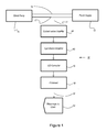
- monitor 16 can include current-sense amplifier 44 in one implementation.
- Appropriate current-sense amplifiers can detect the current as analog signal 42 from conductor 17 and condition ( e.g. , amplify, filter, etc.) the signal 42.
- Current-sense amplifier 44 can be an integrated circuit. Any appropriate current-sense amplifier can be used in monitor 16.
- current-sense amplifier 44 can be a differential current-sense amplifier, a high-accuracy current-sense amplifier, a high-side current-sense amplifier, and a high voltage current-sense amplifier.
- Appropriate current-sense amplifiers for use in monitor 16 can be MAXIMTM high-side current-sense amplifiers, such as, MAX4173, MAX4173F, MAX4173H, and MAX4173T, high-side current-sense amplifiers.
- the current-sense amplifier 44 includes a current sensor coupled with a signal-conditioning amplifier.
- the current sensor can be implemented using many techniques. For example, different current sensors include a voltage drop across an in-line resistor, a Hall sensor-based device, or a current transformer.
- the signal-conditioning amplifier can receive the detected current and condition it for later use. For example, the detected signal can be amplified so that current changes have greater absolute changes and are therefore easier to measure or conform to expected input for subsequent current detection circuitry.
- monitor 16 can include operational amplifier 46 in some implementations.
- an appropriate operational amplifier can amplify small signals from current-sense amplifier 44.
- Operational amplifier 46 can be any appropriate operational amplifiers (e.g. , an inverting amplifier, a non-inverting amplifier, a second-order low pass or high pass filter, or a single, dual or quad micropower operational amplifier). Examples of operational amplifiers include, without limitation MAXIMTM MAX4162, MAX4163, and MAX4164, operational amplifiers.
- monitor 16 can include analog-to-digital (A/D) converter 48.
- A/D converter 48 can be any device for converting analog signal 42 to discrete digital signals.
- A/D converter 48 can be an integrated circuit.
- a digital signal output can use coding schemes such as binary, Gray code or two's complement binary.
- monitor 16 can include digital signal processor 50.
- an appropriate processor can decrypt digital signals from A/D converter 48, and convert the digital signals into information signal 52.
- processor 50 can compare the magnitude of current detected to a reference value to determine whether the current detected in conductor 17 has increased, indicating a failure of conductor 15, or decreased, indicating a failure of conductor 17, or is unchanged, indicating continuity of conductors 17 and 15.
- informational signal 52 can be a signal communicating loss of current or conductor failure.
- information signal 52 can be stored and/or communicated to user 54 via message.
- a user can be a blood pump recipient, or a service technician.
- information signal 52 can be transmitted to a system controller.
- information signal 52 can be processed to trigger an audible alarm, a LED, or an icon on an LCD of a system controller to indicate conductor failure.
- blood pump system 11 can include blood pump 10 and external power supply 12.
- blood pump 10 can be connected to external power supply 12 by electrical cable 14.
- blood pump system 11 can include monitor 16 to detect conductor failure in electrical cable 14.
- blood pump system 11 can include more than one monitor 16.
- blood pump system 11 can include a monitor for each group of redundant conductors. For example, if a cable connecting two components of a blood pump system houses three groups of redundant cables, a blood pump system can include an array of three monitors, which can be configured to detect a change in current carried by a single conductor of the group.
- a blood pump system having four groups of redundant conductors, with two, three, four, five or six conductors in each group ( i.e., eight, twelve, sixteen, twenty, or twenty-four conductors in total), and can include four monitors.
- blood pump system 11 can include system controller 18.
- system controller 18 can receive power from external power supply 12, and distribute power to blood pump 10 via system cables 14.
- system controller 18 can receive signals from monitor 16 for conveying information regarding conductor failure to a blood pump recipient, or a service technician.
- an appropriate blood pump can be an electrically-driven pump for providing mechanical circulatory support.
- external blood pumps e.g. , cardiac bypass devices
- implanted blood pumps e.g. , ventricular assist devices (VADs)
- VADs ventricular assist devices
- any appropriate source of power can be used in a blood pump system provided herein.
- electrical outlets, external batteries, and implanted batteries can be appropriate power supplies.
- External batteries can include a battery pack or packs.
- a battery pack can carry at least two batteries.
- a battery can be any type of battery required to provide power to a blood pump system.
- a suitable battery can be a primary battery or a rechargeable battery.
- any appropriate cable can be used as a blood pump system cable.
- an electrical cable or percutaneous cable can be used in a blood pump system described herein.
- a cable can be permanently attached or releasably attached to a device.
- some cables can feature connectors for releasable attachment to a device.
- a blood pump system provided herein can include any appropriate device to command, direct or regulate the activity of components of a blood pump system (e.g. , a system controller).
- a system controller can house a monitor for detecting conductor discontinuity as described herein.
- a system controller can house a monitor for each group of redundant conductors. For example, if a system cable included three groups of redundant conductors, a system controller can house an array of three monitors configured to detect a change in current in a single conductor of the group.
- system controller 18 can be an external controller.
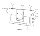
- a controller can feature cable connectors 28 and 30.
- system controller 18 can have cable connectors 28 for receiving power cables and a drive-line connector 30 for receiving a percutaneous lead.
- connectors 28 and 30 can be on one side of system controller 18, and directed in a single direction.
- connector 30 can include a safety mechanism to reduce the risk of accidental disconnection of a percutaneous lead.
- system controller 18 can feature rounded corners for recipient comfort.
- system controller 18 can include multiple components for communicating information regarding the status of a heart pump system to a recipient, a caregiver, or a service technician.
- a system controller can include an audible alarm, integrated liquid crystal display (LCD) panel 22, and light emitting diode 32.
- LED 32 and LCD panel 22 can communicate power connectivity, pump system status, and alarm history.
- a system controller can include several LEDs. For example, one LED can communicate power connectivity, and another LED can communicate drive-line connectivity.
- LED 32 and LCD panel 22 are located on the front face of system controller 18. In some cases, LED 32 and LCD panel 22 can be oriented so they can be read by a recipient looking downward.
- System controller 18 can include control button 34 to access information provided through LCD panel 22.
- a system controller can have up to three control buttons. For example, one button can be pressed to illuminate a battery gauge, and another button can silence an audible alarm.
- simultaneous depression of multiple buttons, or prolonged depression of a single button can actuate hidden and semi-hidden features (e.g. , features for setting pump parameters). For example, changing pump speed can be a hidden function accessed by a clinician, or accessed by a recipient with clinician assistance.
- any appropriate LCD screen can be included in a system controller described herein.
- an appropriate LCD can enable patients and caregivers to attain data on power consumption, pump speed, flow, pulsatility index (i.e. , quantification of the oscillations of the arterial blood-flow velocity waveform), pump and system status, and recent event history.
- a LCD can support remote diagnosing.
- data can be accessed through a LCD display by single button control. For example, to view speed setting, flow, pulsatility index, or power, a user can press a display control button, and cycle through read-outs for these data points.
- an LED can be a colored light (e.g., a red, yellow, or green light).
- an appropriate LED can be designed for user-friendly communication (e.g ., illuminating an icon).
- an appropriate LED can provide information regarding battery status, routine maintenance needs, or system failures that require immediate service.
- illumination of an icon can clarify a cause of an audible alarm (e.g. , power loss or drive-line disconnection).
- a system controller can include multi-sensory alarms.
- icons, LEDs, auditory signals, and LCD display screen can provide primary and secondary levels of information to users.
- LEDs and audible alarms can provide primary communication of status, alarms, and advisories.
- red LEDs in combination with a steady auditory tone, can be used to communicate urgency, and a need for immediate action and response.
- advisories can be communicated through use of yellow LEDs and an audible intermittent tone.
- a display screen can communicate secondary information about alarms, and status for non-routine events.
- system controller 18 can include attachment site 36 for attaching a lanyard or other strap, and belt clip 40.
- a system controller can include up to three attachment clips.
- LED 32 (previously shown in FIG. 3A ) can be placed on the top of system controller 18 so it can be seen by a recipient looking downward.
- system controller 18 can include an internal back-up battery 20.
- an appropriate back-up battery can be any battery that can operate a blood pump for 5-15 minutes in the event that cables for external power become disconnected from connectors 28.
- a back-up battery can power an audible or visual signal (e.g. , an alarm).
- System controller 18 can include belt clip 40.
- a belt-clip can be any appropriate clip for securing a blood pump system controller to a belt worn by a recipient.
- belt-clip 40 can be an articulating belt clip.
- belt clip 40 can be a removable belt clip.
- belt clip 40 can be capable of rotation. For example, belt clip 40 can capable of being rotated at least 180 degrees.
- System controller 18 can include attachment site 36.
- An attachment site can be any part of the housing of a controller that can be secured to a strap or lanyard. Any appropriate strap or lanyard can be attached to an attachment site on a system controller. Appropriate straps can support a system controller and be worn or carried by a blood pump recipient. In some cases, a system controller can have several attachment sites.
- methods provided herein can include detecting current flowing in a single conductor of a group of redundant conductors, for example, without detecting current in any other conductor of the group.
- a method can include comparing a detected current to a reference value to determine whether there has been a change in the magnitude of current carried by a single conductor.
- the reference value is not a pre-set reference value, but a reference value that fluctuates based on the actual current consumption of the system.
- the reference value may be based, or wholly derived from, one conductor's current. This reference conductor's current can be compared to a second conductor's current in real-time to determine whether the second conductor is operating as expected.
- a detected current can be less than a reference value. For example, if a conductor being directly monitored has failed, the detected current can be less than a reference value. In some cases, a detected current can be greater than a reference value. For example, if one or more indirectly monitored conductors has failed, the detected current in a directly monitored conductor can be greater than a reference value. In some cases, a detected current can be equal to a reference value. For example, if all conductors of a group are continuous, the detected current, in a single conductor being directly monitored, can be substantially equal to the reference value. In some cases, a method provided herein can include continuous monitoring.
- a method can include re-detecting current in a single conductor, until a change is determined.
- information about conductor discontinuity can be communicated to a blood pump user (e.g. , a recipient or clinician).
- compromised integrity refers to testing the current flowing in an electrical conductor and determining whether a conductor has been compromised.
- compromised integrity can be discontinuity due to conductor failure, fracture, or wear.
- compromised integrity can be intermittent, sporadic, or stable.
- monitoring integrity can refer to determining whether a monitored conductor is carrying excess current. For example, a conductor discontinuity can result in a monitored conductor carrying 0.5, 0.75, or 1 times more current than a conductor would carry if there were no discontinuity. As previously discussed, shorts also can be detected in an analogous fashion. In some cases, monitoring integrity can refer to determining whether a monitored conductor is carrying zero current.
- Conductor integrity can be tested or assessed by any technique or device that can detect current and determine whether the current detected is greater than or less than a reference value.
- the amount of current carried by a single conductor in a group of two or more conductors can be measured using a multimeter, current-sense transducer, or a series of integrated circuits ( e.g. , Figure 1 ), and compared with a reference value.
- a reference value can be the amount of current that would be present in a single conductor if the integrity of all conductors were intact.
- a reference value can be a value from a previous test of conductor continuity.
- a reference value can be a value determined when a device was manufactured, installed, or serviced.
- a reference value for a medical device e.g. , a VAD
- VAD a test value detected at the time a device was surgically implanted in a recipient.
- the reference value is obtained from a second monitored redundant pair.
- current consumption may change during different phases of the cardiac cycle and with patient condition.
- the reference value may need to change correspondingly during the cardiac cycle, for each patient, and for different times during the patient's use of the VAD (e.g. , the current consumption may decrease if the patient's heart strengthens and is able to move more blood independently). Consequently, the reference value may change also.
- Obtaining the reference value from a second monitored redundant conductor that is also supplying current to the system provides a reference value that reflects the instant current needs of the system.
- a reference value can be used to determine conductor integrity. For example, if a reference value is greater than a test value, the difference indicates a failure in a monitored conductor. In some cases, if a reference value is less than a test value, the difference can indicate a failure of one or more other conductors in a group of redundant conductors. For example, a pair of redundant conductors can carry between about 100 mA and 700 mA. In some cases, a reference value for a conductor of a pair of redundant conductors can be from 100 mA to about 400 mA. In some cases, a test value for a monitored conductor less than 100 mA can indicate a failure, or discontinuity in a monitored conductor. In some cases, a test value for a monitored conductor greater than 400 mA can indicate a failure in an unmonitored conductor.
- a group of redundant conductors can be two or more conductors that share current load of a circuit.
- each conductor in a pair of conductors can carry about 50% of the current load of a circuit.
- a group of redundant conductors can include two, three, four, or more conductors in a group of redundant conductors.
- each conductor of a group can carry a substantially equal share of the current carried by the group.
- a conductor of a group of three, four, five, or six redundant conductors can carry about 33%, 25%, 20%, or 17% of the current carried by a group of redundant conductors.
- information about conductor integrity can be provided to a user.
- information about conductor continuity/discontinuity can be communicated to a blood pump recipient, a clinician, or a service technician.
- information can be communicated through a system controller, via an audible or visual alarm.
- information about conductor continuity can be stored in an event log in a system controller, and displayed on an LCD screen.
- the information provided can display details about a discontinuity (e.g. , whether the integrity of a monitored conductor or an unmonitored conductor has been compromised.)
Landscapes
- Health & Medical Sciences (AREA)
- Heart & Thoracic Surgery (AREA)
- Engineering & Computer Science (AREA)
- Cardiology (AREA)
- Hematology (AREA)
- Mechanical Engineering (AREA)
- Anesthesiology (AREA)
- Biomedical Technology (AREA)
- Life Sciences & Earth Sciences (AREA)
- Animal Behavior & Ethology (AREA)
- General Health & Medical Sciences (AREA)
- Public Health (AREA)
- Veterinary Medicine (AREA)
- Vascular Medicine (AREA)
- Physics & Mathematics (AREA)
- General Physics & Mathematics (AREA)
- External Artificial Organs (AREA)
Applications Claiming Priority (3)
| Application Number | Priority Date | Filing Date | Title |
|---|---|---|---|
| US12/472,812 US9782527B2 (en) | 2009-05-27 | 2009-05-27 | Monitoring of redundant conductors |
| PCT/US2010/036439 WO2010138742A1 (en) | 2009-05-27 | 2010-05-27 | Monitoring of redundant conductors |
| EP10728950.6A EP2435105B1 (de) | 2009-05-27 | 2010-05-27 | Überwachung von redundanten leitern |
Related Parent Applications (2)
| Application Number | Title | Priority Date | Filing Date |
|---|---|---|---|
| EP10728950.6 Division | 2010-05-27 | ||
| EP10728950.6A Division EP2435105B1 (de) | 2009-05-27 | 2010-05-27 | Überwachung von redundanten leitern |
Publications (3)
| Publication Number | Publication Date |
|---|---|
| EP2599510A2 true EP2599510A2 (de) | 2013-06-05 |
| EP2599510A3 EP2599510A3 (de) | 2018-03-28 |
| EP2599510B1 EP2599510B1 (de) | 2021-10-20 |
Family
ID=42731715
Family Applications (2)
| Application Number | Title | Priority Date | Filing Date |
|---|---|---|---|
| EP10728950.6A Ceased EP2435105B1 (de) | 2009-05-27 | 2010-05-27 | Überwachung von redundanten leitern |
| EP13157207.5A Not-in-force EP2599510B1 (de) | 2009-05-27 | 2010-05-27 | Steuergerät für ein blutpumpensystem |
Family Applications Before (1)
| Application Number | Title | Priority Date | Filing Date |
|---|---|---|---|
| EP10728950.6A Ceased EP2435105B1 (de) | 2009-05-27 | 2010-05-27 | Überwachung von redundanten leitern |
Country Status (6)
| Country | Link |
|---|---|
| US (2) | US9782527B2 (de) |
| EP (2) | EP2435105B1 (de) |
| JP (2) | JP5580885B2 (de) |
| AU (1) | AU2010253836B2 (de) |
| CA (1) | CA2763029C (de) |
| WO (1) | WO2010138742A1 (de) |
Cited By (22)
| Publication number | Priority date | Publication date | Assignee | Title |
|---|---|---|---|---|
| US11996699B2 (en) | 2018-05-02 | 2024-05-28 | Kardion Gmbh | Receiving unit, transmission unit, power transmission system and method for wireless power transmission |
| US12102835B2 (en) | 2018-05-02 | 2024-10-01 | Kardion Gmbh | Transmission unit comprising a transmission coil and a temperature sensor |
| US12144976B2 (en) | 2018-06-21 | 2024-11-19 | Kardion Gmbh | Method and device for detecting a wear condition of a ventricular assist device and for operating same, and ventricular assist device |
| US12150647B2 (en) | 2016-06-06 | 2024-11-26 | Kardion Gmbh | Method for punching a lumen and implanting an implant device |
| US12178554B2 (en) | 2018-06-06 | 2024-12-31 | Kardion Gmbh | Systems and methods for determining a viscosity of a fluid |
| US12194287B2 (en) | 2018-05-30 | 2025-01-14 | Kardion Gmbh | Method of manufacturing electrical conductor tracks in a region of an intravascular blood pump |
| US12201821B2 (en) | 2018-06-06 | 2025-01-21 | Kardion Gmbh | Method for determining a flow rate of a fluid flowing through an implanted vascular support system, and implantable vascular support system |
| US12222267B2 (en) | 2018-06-06 | 2025-02-11 | Kardion Gmbh | Analysis device and method for analyzing a viscosity of a fluid |
| US12230868B2 (en) | 2018-05-02 | 2025-02-18 | Kardion Gmbh | Device for inductive energy transfer into a human body, for example, and use of said device |
| US12233250B2 (en) | 2018-05-02 | 2025-02-25 | Kardion Gmbh | Device for inductive energy transmission into a human body and use thereof |
| US12257424B2 (en) | 2018-06-06 | 2025-03-25 | Kardion Gmbh | Implantable ventricular assist system and method for operating same |
| US12310708B2 (en) | 2018-06-06 | 2025-05-27 | Kardion Gmbh | Systems and methods for determining a flow speed of a fluid flowing through a cardiac assist device |
| US12311160B2 (en) | 2018-06-06 | 2025-05-27 | Kardion Gmbh | Method and system for determining the speed of sound in a fluid in the region of a cardiac support system |
| US12324906B2 (en) | 2018-06-06 | 2025-06-10 | Kardion Gmbh | Systems and methods for determining a total blood volume flow in a cardiac support system and vascular support system |
| US12377256B2 (en) | 2018-06-06 | 2025-08-05 | Kardion Gmbh | Cardiac support system flow measurement using pressure sensors |
| US12400788B2 (en) | 2020-11-05 | 2025-08-26 | Kardion Gmbh | Device for inductive energy transmission in a human body and use of the device |
| US12403296B2 (en) | 2018-05-30 | 2025-09-02 | Kardion Gmbh | Apparatus for anchoring a ventricular assist system in a blood vessel, operating method, production method for producing an apparatus and ventricular assist system |
| US12476488B2 (en) | 2018-05-02 | 2025-11-18 | Kardion Gmbh | Energy transfer system and reception unit for the wireless transcutaneous transfer of energy |
| US12478267B2 (en) | 2018-06-06 | 2025-11-25 | Kardion Gmbh | Sensor head device for a minimal invasive ventricular assist device and method for producing such a sensor head device |
| US12491357B2 (en) | 2018-06-06 | 2025-12-09 | Kardion Gmbh | Systems and methods for determining a blood volume flow through a cardiac support system and vascular support system |
| US12508418B2 (en) | 2018-08-08 | 2025-12-30 | Kardion Gmbh | Device and method for monitoring the state of health of a patient |
| US12569671B2 (en) | 2018-06-06 | 2026-03-10 | Kardion Gmbh | Device and method for determination of a cardiac output for a cardiac assistance system |
Families Citing this family (67)
| Publication number | Priority date | Publication date | Assignee | Title |
|---|---|---|---|---|
| US9782527B2 (en) | 2009-05-27 | 2017-10-10 | Tc1 Llc | Monitoring of redundant conductors |
| US8562508B2 (en) | 2009-12-30 | 2013-10-22 | Thoratec Corporation | Mobility-enhancing blood pump system |
| WO2012012552A1 (en) | 2010-07-22 | 2012-01-26 | Thoratec Corporation | Controlling implanted blood pumps |
| JP5577506B2 (ja) | 2010-09-14 | 2014-08-27 | ソーラテック コーポレイション | 遠心式ポンプ装置 |
| KR20140015291A (ko) * | 2010-12-09 | 2014-02-06 | 하트웨어, 인코포레이티드 | 이식가능 혈액 펌프용 컨트롤러 및 전원 |
| JP6039586B2 (ja) | 2011-03-02 | 2016-12-07 | ソーラテック コーポレイション | 心室用カフ |
| EP2693609B1 (de) | 2011-03-28 | 2017-05-03 | Thoratec Corporation | Dreh- und antriebsvorrichtung und zentrifugalpumpvorrichtung damit |
| CN202236824U (zh) * | 2011-08-29 | 2012-05-30 | 惠州市华阳医疗电子有限公司 | 具有渗出液流速报警功能的负压伤口治疗系统 |
| USD751200S1 (en) | 2011-12-08 | 2016-03-08 | Heartware, Inc. | Controller for implantable blood pump |
| US9199019B2 (en) | 2012-08-31 | 2015-12-01 | Thoratec Corporation | Ventricular cuff |
| US9981076B2 (en) | 2012-03-02 | 2018-05-29 | Tc1 Llc | Ventricular cuff |
| EP2822614B1 (de) | 2012-03-05 | 2016-12-28 | Thoratec Corporation | Modulare implantierbare medizinische pumpe |
| US8837096B2 (en) | 2012-03-13 | 2014-09-16 | Thoratec Corporation | Fault monitor for fault tolerant implantable pump |
| US20140066689A1 (en) * | 2012-09-04 | 2014-03-06 | Terumo Kabushiki Kaisha | Integrated Controller For Ventricular Assist Device |
| US10124102B2 (en) | 2012-12-20 | 2018-11-13 | Oran Bulent | Endovascular permanent heart assist device |
| US8968174B2 (en) * | 2013-01-16 | 2015-03-03 | Thoratec Corporation | Motor fault monitor for implantable blood pump |
| US9371826B2 (en) | 2013-01-24 | 2016-06-21 | Thoratec Corporation | Impeller position compensation using field oriented control |
| US9556873B2 (en) | 2013-02-27 | 2017-01-31 | Tc1 Llc | Startup sequence for centrifugal pump with levitated impeller |
| US9192705B2 (en) * | 2013-03-25 | 2015-11-24 | Thoratec Corporation | Percutaneous cable with redundant conductors for implantable blood pump |
| US10052420B2 (en) | 2013-04-30 | 2018-08-21 | Tc1 Llc | Heart beat identification and pump speed synchronization |
| US10039878B2 (en) * | 2013-05-07 | 2018-08-07 | Carefusion 303, Inc. | Method for reliable intermodule connection in an infusion system |
| EP3131600B1 (de) * | 2014-04-15 | 2021-06-16 | Tc1 Llc | Verfahren und systeme zur bereitstellung von batteriefeedback an patienten |
| US9623161B2 (en) | 2014-08-26 | 2017-04-18 | Tc1 Llc | Blood pump and method of suction detection |
| WO2016044889A2 (en) * | 2014-09-23 | 2016-03-31 | St Vincent's Hospital (Sydney) Limited | Method and apparatus for determining aortic valve opening |
| EP4643926A3 (de) | 2015-02-11 | 2025-12-24 | Tc1 Llc | Herzschlagidentifizierung und pumpengeschwindigkeitssynchronisierung |
| US10371152B2 (en) | 2015-02-12 | 2019-08-06 | Tc1 Llc | Alternating pump gaps |
| US10166318B2 (en) | 2015-02-12 | 2019-01-01 | Tc1 Llc | System and method for controlling the position of a levitated rotor |
| US10245361B2 (en) | 2015-02-13 | 2019-04-02 | Tc1 Llc | Impeller suspension mechanism for heart pump |
| EP3340925B1 (de) | 2015-08-28 | 2020-09-23 | Tc1 Llc | Blutpumpensteuergeräte und verfahren zur verwendung für verbesserte energieeffizienz |
| US10117983B2 (en) | 2015-11-16 | 2018-11-06 | Tc1 Llc | Pressure/flow characteristic modification of a centrifugal pump in a ventricular assist device |
| EP3395019B1 (de) | 2015-12-21 | 2022-03-30 | Google LLC | Automatische vorschläge und andere inhalte für nachrichtenübermittlungsanwendungen |
| KR20180093040A (ko) | 2015-12-21 | 2018-08-20 | 구글 엘엘씨 | 메시지 교환 스레드들에 대한 자동적인 제안들 |
| CN108697836B (zh) * | 2016-02-25 | 2024-10-25 | 心脏器械股份有限公司 | 具有车辆适配器和电池的电源 |
| US10387461B2 (en) | 2016-08-16 | 2019-08-20 | Google Llc | Techniques for suggesting electronic messages based on user activity and other context |
| US10894116B2 (en) | 2016-08-22 | 2021-01-19 | Tc1 Llc | Heart pump cuff |
| WO2018057541A1 (en) | 2016-09-20 | 2018-03-29 | Google Llc | Suggested responses based on message stickers |
| US10015124B2 (en) * | 2016-09-20 | 2018-07-03 | Google Llc | Automatic response suggestions based on images received in messaging applications |
| WO2018057536A1 (en) | 2016-09-20 | 2018-03-29 | Google Llc | Bot requesting permission for accessing data |
| WO2018057795A1 (en) | 2016-09-26 | 2018-03-29 | Tc1 Llc | Heart pump driveline power modulation |
| US10416846B2 (en) | 2016-11-12 | 2019-09-17 | Google Llc | Determining graphical element(s) for inclusion in an electronic communication |
| US10146768B2 (en) | 2017-01-25 | 2018-12-04 | Google Llc | Automatic suggested responses to images received in messages using language model |
| US11235137B2 (en) | 2017-02-24 | 2022-02-01 | Tc1 Llc | Minimally invasive methods and devices for ventricular assist device implantation |
| US10860854B2 (en) | 2017-05-16 | 2020-12-08 | Google Llc | Suggested actions for images |
| EP3634528B1 (de) | 2017-06-07 | 2023-06-07 | Shifamed Holdings, LLC | Intravaskuläre fluidbewegungsvorrichtungen, systeme und verwendungsverfahren |
| US10404636B2 (en) | 2017-06-15 | 2019-09-03 | Google Llc | Embedded programs and interfaces for chat conversations |
| US10348658B2 (en) | 2017-06-15 | 2019-07-09 | Google Llc | Suggested items for use with embedded applications in chat conversations |
| US11511103B2 (en) | 2017-11-13 | 2022-11-29 | Shifamed Holdings, Llc | Intravascular fluid movement devices, systems, and methods of use |
| US11317872B2 (en) | 2017-12-15 | 2022-05-03 | Mayo Foundation For Medical Education And Research | Predicting transient ischemic events using ECG data |
| US10891526B2 (en) | 2017-12-22 | 2021-01-12 | Google Llc | Functional image archiving |
| EP3746149B1 (de) | 2018-02-01 | 2025-08-06 | Shifamed Holdings, LLC | Intravaskuläre blutpumpen |
| JP6897603B2 (ja) * | 2018-02-28 | 2021-06-30 | オムロン株式会社 | ケーブル断線予兆検知装置 |
| US11389641B2 (en) * | 2018-03-21 | 2022-07-19 | Tc1 Llc | Modular flying lead cable and methods for use with heart pump controllers |
| DE102018208549A1 (de) | 2018-05-30 | 2019-12-05 | Kardion Gmbh | Elektronikmodul für ein Herzunterstützungssystem und Verfahren zum Herstellen eines Elektronikmoduls für ein Herzunterstützungssystem |
| DE102018208539A1 (de) | 2018-05-30 | 2019-12-05 | Kardion Gmbh | Motorgehäusemodul zum Abdichten eines Motorraums eines Motors eines Herzunterstützungssystems und Herzunterstützungssystem und Verfahren zum Montieren eines Herzunterstützungssystems |
| WO2020028537A1 (en) | 2018-07-31 | 2020-02-06 | Shifamed Holdings, Llc | Intravascaular blood pumps and methods of use |
| WO2020073047A1 (en) | 2018-10-05 | 2020-04-09 | Shifamed Holdings, Llc | Intravascular blood pumps and methods of use |
| WO2021011473A1 (en) | 2019-07-12 | 2021-01-21 | Shifamed Holdings, Llc | Intravascular blood pumps and methods of manufacture and use |
| US11654275B2 (en) | 2019-07-22 | 2023-05-23 | Shifamed Holdings, Llc | Intravascular blood pumps with struts and methods of use and manufacture |
| US12465748B2 (en) | 2019-08-07 | 2025-11-11 | Supira Medical, Inc. | Catheter blood pumps and collapsible pump housings |
| US11724089B2 (en) | 2019-09-25 | 2023-08-15 | Shifamed Holdings, Llc | Intravascular blood pump systems and methods of use and control thereof |
| WO2021062260A1 (en) | 2019-09-25 | 2021-04-01 | Shifamed Holdings, Llc | Catheter blood pumps and collapsible blood conduits |
| EP4501393A3 (de) | 2019-09-25 | 2025-04-09 | Shifamed Holdings, LLC | Katheterblutpumpen und zusammenklappbare pumpengehäuse |
| EP4072650A4 (de) | 2019-12-11 | 2024-01-10 | Shifamed Holdings, LLC | Absteigende aorten- und hohlvenenblutpumpen |
| EP4077947A4 (de) | 2019-12-19 | 2024-01-10 | Shifamed Holdings, LLC | Intravaskuläre blutpumpen, motoren und fluidsteuerung |
| US12502524B2 (en) | 2021-12-03 | 2025-12-23 | Kardion Gmbh | Cardiac pump with optical fiber for laser doppler |
| US12235889B2 (en) | 2022-08-26 | 2025-02-25 | Google Llc | Device messages provided in displayed image compilations based on user content |
| WO2024073315A1 (en) * | 2022-09-29 | 2024-04-04 | Baker Hughes Holdings Llc | Precise number selection in one-handed operative equipment |
Family Cites Families (84)
| Publication number | Priority date | Publication date | Assignee | Title |
|---|---|---|---|---|
| US3097366A (en) * | 1963-07-16 | Winchell | ||
| US4068105A (en) * | 1976-05-28 | 1978-01-10 | American District Telegraph Company | Central station system transmission apparatus |
| US4227145A (en) * | 1977-10-19 | 1980-10-07 | Bicc Limited | Apparatus for detecting faults in electric cables |
| US4199029A (en) * | 1978-04-10 | 1980-04-22 | Fike Metal Products Corporation | Multiple, independently actuatable fire suppression devices each having individual actuating power source |
| US4888011A (en) * | 1988-07-07 | 1989-12-19 | Abiomed, Inc. | Artificial heart |
| US5250894A (en) * | 1992-03-31 | 1993-10-05 | Bridges Electric, Inc. | Current sensing system having electronic compensation circuits for conditioning the outputs of current sensors |
| EP0563695B1 (de) * | 1992-03-31 | 1999-05-26 | Siemens Aktiengesellschaft | Verfahren und Anordnung zur Erkennung von Kurzschlüssen in Leitungsabzweigen von elektrischen Netzen |
| US5332973A (en) * | 1992-05-01 | 1994-07-26 | The University Of Manitoba | Built-in fault testing of integrated circuits |
| US5325062A (en) * | 1992-07-10 | 1994-06-28 | Sequoia Systems, Inc. | Apparatus and method for detection of latent faults in redundant systems |
| US5947892A (en) | 1993-11-10 | 1999-09-07 | Micromed Technology, Inc. | Rotary blood pump |
| EP1402908A3 (de) * | 1994-04-15 | 2005-04-27 | Allegheny-Singer Research Institute | Blutpumpe und Herstellungsverfahren |
| FR2724393A1 (fr) * | 1994-09-12 | 1996-03-15 | Inst Nat Sante Rech Med | Obtention d'un anticorps monoclonal recombinant humanise a partir d'un anticorps monoclonal murin, sa production en cellules d'insecte, et ses utilisations |
| US5613935A (en) * | 1994-12-16 | 1997-03-25 | Jarvik; Robert | High reliability cardiac assist system |
| US5725357A (en) | 1995-04-03 | 1998-03-10 | Ntn Corporation | Magnetically suspended type pump |
| US5713954A (en) * | 1995-06-13 | 1998-02-03 | Abiomed R&D, Inc. | Extra cardiac ventricular assist device |
| US5947703A (en) | 1996-01-31 | 1999-09-07 | Ntn Corporation | Centrifugal blood pump assembly |
| US5840070A (en) | 1996-02-20 | 1998-11-24 | Kriton Medical, Inc. | Sealless rotary blood pump |
| IES960198A2 (en) * | 1996-03-01 | 1996-10-16 | Suparules Ltd | Apparatus for measuring an A.C. current in a cable |
| US5733313A (en) | 1996-08-01 | 1998-03-31 | Exonix Corporation | RF coupled, implantable medical device with rechargeable back-up power source |
| US5894273A (en) | 1996-08-26 | 1999-04-13 | Fairway Medical Technologies, Inc. | Centrifugal blood pump driver apparatus |
| AUPO902797A0 (en) * | 1997-09-05 | 1997-10-02 | Cortronix Pty Ltd | A rotary blood pump with hydrodynamically suspended impeller |
| US5904646A (en) * | 1997-09-08 | 1999-05-18 | Jarvik; Robert | Infection resistant power cable system for medically implanted electric motors |
| AU9787498A (en) * | 1997-10-02 | 1999-04-27 | Micromed Technology, Inc. | Implantable pump system |
| KR20010071171A (ko) | 1998-04-22 | 2001-07-28 | 톰 메이져 | 하이브리드 자기 베어링을 갖춘 이식가능한 원심 혈액펌프 |
| EP0989656B1 (de) * | 1998-09-24 | 2009-03-11 | Levitronix LLC | Permanentmagnetisch erregter elektrischer Drehantrieb |
| US6511412B1 (en) * | 1998-09-30 | 2003-01-28 | L. Vad Technology, Inc. | Cardivascular support control system |
| US6149683A (en) * | 1998-10-05 | 2000-11-21 | Kriton Medical, Inc. | Power system for an implantable heart pump |
| US6264635B1 (en) | 1998-12-03 | 2001-07-24 | Kriton Medical, Inc. | Active magnetic bearing system for blood pump |
| US6264601B1 (en) * | 1999-04-02 | 2001-07-24 | World Heart Corporation | Implantable ventricular assist device |
| US6234772B1 (en) | 1999-04-28 | 2001-05-22 | Kriton Medical, Inc. | Rotary blood pump |
| US6146325A (en) | 1999-06-03 | 2000-11-14 | Arrow International, Inc. | Ventricular assist device |
| US7138776B1 (en) | 1999-07-08 | 2006-11-21 | Heartware, Inc. | Method and apparatus for controlling brushless DC motors in implantable medical devices |
| DE60006926T2 (de) | 1999-12-27 | 2004-06-17 | Terumo K.K. | Flüssigkeitspumpe mit magnetisch aufgehängtem Laufrad |
| CZ305727B6 (cs) | 2000-03-27 | 2016-02-24 | The Cleveland Clinic Foundation | Pomocný přístroj pro pacienty s onemocněním srdce a způsob řízení průtoku krve krevní pumpou |
| JP2001336528A (ja) | 2000-05-25 | 2001-12-07 | Ntn Corp | 磁気浮上装置 |
| US6589030B2 (en) | 2000-06-20 | 2003-07-08 | Ntn Corporation | Magnetically levitated pump apparatus |
| DE10041728A1 (de) * | 2000-08-25 | 2002-03-21 | Implex Hear Tech Ag | Implantierbare medizinische Vorrichtung mit einem hermetisch dichten Gehäuse |
| US6626644B2 (en) | 2000-10-30 | 2003-09-30 | Ntn Corporation | Magnetically levitated pump and controlling circuit |
| AU2002225701A1 (en) | 2000-11-14 | 2002-05-27 | Airex Corporation | Integrated magnetic bearing |
| DE10123138B4 (de) | 2001-04-30 | 2007-09-27 | Berlin Heart Ag | Verfahren zur Lageregelung eines permanentmagnetisch gelagerten rotierenden Bauteils |
| DE10123139B4 (de) | 2001-04-30 | 2005-08-11 | Berlin Heart Ag | Verfahren zur Regelung einer Unterstützungspumpe für Fluidfördersysteme mit pulsatilem Druck |
| US7396327B2 (en) | 2002-01-07 | 2008-07-08 | Micromed Technology, Inc. | Blood pump system and method of operation |
| US6901212B2 (en) | 2002-06-13 | 2005-05-31 | Halliburton Energy Services, Inc. | Digital adaptive sensorless commutational drive controller for a brushless DC motor |
| US6949066B2 (en) * | 2002-08-21 | 2005-09-27 | World Heart Corporation | Rotary blood pump diagnostics and cardiac output controller |
| US6817836B2 (en) | 2002-09-10 | 2004-11-16 | Miwatec Incorporated | Methods and apparatus for controlling a continuous flow rotary blood pump |
| US7284956B2 (en) | 2002-09-10 | 2007-10-23 | Miwatec Co., Ltd. | Methods and apparatus for controlling a continuous flow rotary blood pump |
| US7511443B2 (en) | 2002-09-26 | 2009-03-31 | Barrett Technology, Inc. | Ultra-compact, high-performance motor controller and method of using same |
| JP2006508767A (ja) * | 2002-12-06 | 2006-03-16 | ワールド・ハート・コーポレイション | 小型拍動性移植可能心室補助デバイスおよび心室補助デバイスを制御する方法 |
| EP1486217B1 (de) * | 2003-06-12 | 2010-05-12 | Terumo Kabushiki Kaisha | Pumpensystem für ein künstliches Herz und Steuerungsgerät dafür |
| DE10330434A1 (de) | 2003-07-04 | 2005-02-03 | Jostra Ag | Zentrifugal-Pumpe |
| JP4521547B2 (ja) | 2004-04-15 | 2010-08-11 | 株式会社サンメディカル技術研究所 | 血液ポンプの流量推定装置 |
| US7591777B2 (en) | 2004-05-25 | 2009-09-22 | Heartware Inc. | Sensorless flow estimation for implanted ventricle assist device |
| JP2008512195A (ja) | 2004-09-07 | 2008-04-24 | マイクロメツド・カーデイオバスキユラー・インコーポレイテツド | 血液ポンプの生理学的制御のための方法およびシステム |
| JP2006167142A (ja) | 2004-12-15 | 2006-06-29 | Terumo Corp | 血液ポンプシステム |
| CA2611313A1 (en) | 2005-06-06 | 2006-12-14 | The Cleveland Clinic Foundation | Blood pump |
| WO2007053881A1 (en) * | 2005-11-08 | 2007-05-18 | Ventrassist Pty Ltd | Improvements to control systems and power systems for rotary blood pumps |
| US20070142696A1 (en) * | 2005-12-08 | 2007-06-21 | Ventrassist Pty Ltd | Implantable medical devices |
| JP5155186B2 (ja) | 2006-01-13 | 2013-02-27 | ハートウェア、インコーポレイテッド | 回転式血液ポンプ |
| CA2636105C (en) | 2006-01-27 | 2015-05-05 | Circulite, Inc | Heart assist system |
| WO2007109555A2 (en) * | 2006-03-16 | 2007-09-27 | Power Monitors, Inc. | Underground monitoring system and method |
| JP2008202974A (ja) | 2007-02-16 | 2008-09-04 | Nippon Steel Engineering Co Ltd | 給電ケーブルの断線検出方法 |
| CN101678160A (zh) | 2007-04-05 | 2010-03-24 | 麦克罗美德技术公司 | 血泵系统 |
| WO2008154387A1 (en) | 2007-06-06 | 2008-12-18 | Worldheart Corporation | Wearable vad controller with reserve battery |
| US8382830B2 (en) | 2007-06-06 | 2013-02-26 | World Heart Corporation | Implantable VAD with replaceable percutaneous cable |
| JP5201887B2 (ja) * | 2007-06-20 | 2013-06-05 | テルモ株式会社 | 人工心臓用血液ポンプシステムおよび機器監視システム |
| US20110071337A1 (en) | 2008-03-26 | 2011-03-24 | Cardio Assist Ltd. | Heart assist device |
| US7869889B2 (en) * | 2008-07-02 | 2011-01-11 | Saudi Arabian Oil Company | Distributed and adaptive smart logic with multi-communication apparatus for reliable safety system shutdown |
| WO2010036815A2 (en) | 2008-09-26 | 2010-04-01 | Launchpoint Technologies, Inc. | Magnetically-levitated blood pump with optimization method enabling miniaturization |
| JP4996578B2 (ja) | 2008-10-28 | 2012-08-08 | 株式会社サンメディカル技術研究所 | 多孔性構造体を具備する医療用装置又は器具 |
| US8517699B2 (en) | 2008-12-16 | 2013-08-27 | Cleveland Clinic Foundation | Centrifugal pump with offset volute |
| US9782527B2 (en) | 2009-05-27 | 2017-10-10 | Tc1 Llc | Monitoring of redundant conductors |
| US9583991B2 (en) | 2009-06-24 | 2017-02-28 | Synchrony, Inc. | Systems, devices, and/or methods for managing magnetic bearings |
| EP2600918B1 (de) | 2010-08-06 | 2021-10-13 | Heartware, Inc. | Leitvorrichtung zur verwendung mit einem herzunterstützungssystem |
| WO2012071065A1 (en) | 2010-11-23 | 2012-05-31 | Minnetronix Inc. | Portable controller with integral power source for mechanical circulation support systems |
| KR20140015291A (ko) | 2010-12-09 | 2014-02-06 | 하트웨어, 인코포레이티드 | 이식가능 혈액 펌프용 컨트롤러 및 전원 |
| US9492601B2 (en) | 2011-01-21 | 2016-11-15 | Heartware, Inc. | Suction detection on an axial blood pump using BEMF data |
| CA2825354A1 (en) | 2011-01-21 | 2012-07-26 | Heartware, Inc. | Flow estimation in a blood pump |
| US8764621B2 (en) | 2011-07-11 | 2014-07-01 | Vascor, Inc. | Transcutaneous power transmission and communication for implanted heart assist and other devices |
| US9095428B2 (en) | 2012-06-08 | 2015-08-04 | Cameron International Corporation | Artificial heart system |
| US9364596B2 (en) | 2013-01-04 | 2016-06-14 | HeartWave, Inc. | Controller and power source for implantable blood pump |
| US8882477B2 (en) | 2013-03-14 | 2014-11-11 | Circulite, Inc. | Magnetically levitated and driven blood pump and method for using the same |
| DE102013013700A1 (de) | 2013-04-05 | 2014-10-09 | CircuLite GmbH | Implantierbare Blutpumpe, Blutpumpensystem und Verfahren zur Datenübertragung in einem Blutpumpensystem |
| US9427508B2 (en) | 2013-06-04 | 2016-08-30 | Heartware, Inc. | Axial flow pump pressure algorithm |
| KR20160044492A (ko) | 2013-08-14 | 2016-04-25 | 하트웨어, 인코포레이티드 | 축방향 유동 펌프용 임펠러 |
-
2009
- 2009-05-27 US US12/472,812 patent/US9782527B2/en active Active
-
2010
- 2010-05-27 EP EP10728950.6A patent/EP2435105B1/de not_active Ceased
- 2010-05-27 JP JP2012513263A patent/JP5580885B2/ja not_active Expired - Fee Related
- 2010-05-27 WO PCT/US2010/036439 patent/WO2010138742A1/en not_active Ceased
- 2010-05-27 AU AU2010253836A patent/AU2010253836B2/en not_active Ceased
- 2010-05-27 EP EP13157207.5A patent/EP2599510B1/de not_active Not-in-force
- 2010-05-27 CA CA2763029A patent/CA2763029C/en not_active Expired - Fee Related
-
2014
- 2014-02-26 JP JP2014034767A patent/JP5833156B2/ja not_active Expired - Fee Related
-
2015
- 2015-05-21 US US14/719,045 patent/US10350342B2/en active Active
Non-Patent Citations (1)
| Title |
|---|
| None |
Cited By (22)
| Publication number | Priority date | Publication date | Assignee | Title |
|---|---|---|---|---|
| US12150647B2 (en) | 2016-06-06 | 2024-11-26 | Kardion Gmbh | Method for punching a lumen and implanting an implant device |
| US12230868B2 (en) | 2018-05-02 | 2025-02-18 | Kardion Gmbh | Device for inductive energy transfer into a human body, for example, and use of said device |
| US12102835B2 (en) | 2018-05-02 | 2024-10-01 | Kardion Gmbh | Transmission unit comprising a transmission coil and a temperature sensor |
| US12476488B2 (en) | 2018-05-02 | 2025-11-18 | Kardion Gmbh | Energy transfer system and reception unit for the wireless transcutaneous transfer of energy |
| US11996699B2 (en) | 2018-05-02 | 2024-05-28 | Kardion Gmbh | Receiving unit, transmission unit, power transmission system and method for wireless power transmission |
| US12233250B2 (en) | 2018-05-02 | 2025-02-25 | Kardion Gmbh | Device for inductive energy transmission into a human body and use thereof |
| US12403296B2 (en) | 2018-05-30 | 2025-09-02 | Kardion Gmbh | Apparatus for anchoring a ventricular assist system in a blood vessel, operating method, production method for producing an apparatus and ventricular assist system |
| US12194287B2 (en) | 2018-05-30 | 2025-01-14 | Kardion Gmbh | Method of manufacturing electrical conductor tracks in a region of an intravascular blood pump |
| US12257424B2 (en) | 2018-06-06 | 2025-03-25 | Kardion Gmbh | Implantable ventricular assist system and method for operating same |
| US12478267B2 (en) | 2018-06-06 | 2025-11-25 | Kardion Gmbh | Sensor head device for a minimal invasive ventricular assist device and method for producing such a sensor head device |
| US12201821B2 (en) | 2018-06-06 | 2025-01-21 | Kardion Gmbh | Method for determining a flow rate of a fluid flowing through an implanted vascular support system, and implantable vascular support system |
| US12310708B2 (en) | 2018-06-06 | 2025-05-27 | Kardion Gmbh | Systems and methods for determining a flow speed of a fluid flowing through a cardiac assist device |
| US12311160B2 (en) | 2018-06-06 | 2025-05-27 | Kardion Gmbh | Method and system for determining the speed of sound in a fluid in the region of a cardiac support system |
| US12324906B2 (en) | 2018-06-06 | 2025-06-10 | Kardion Gmbh | Systems and methods for determining a total blood volume flow in a cardiac support system and vascular support system |
| US12377256B2 (en) | 2018-06-06 | 2025-08-05 | Kardion Gmbh | Cardiac support system flow measurement using pressure sensors |
| US12569671B2 (en) | 2018-06-06 | 2026-03-10 | Kardion Gmbh | Device and method for determination of a cardiac output for a cardiac assistance system |
| US12178554B2 (en) | 2018-06-06 | 2024-12-31 | Kardion Gmbh | Systems and methods for determining a viscosity of a fluid |
| US12491357B2 (en) | 2018-06-06 | 2025-12-09 | Kardion Gmbh | Systems and methods for determining a blood volume flow through a cardiac support system and vascular support system |
| US12222267B2 (en) | 2018-06-06 | 2025-02-11 | Kardion Gmbh | Analysis device and method for analyzing a viscosity of a fluid |
| US12144976B2 (en) | 2018-06-21 | 2024-11-19 | Kardion Gmbh | Method and device for detecting a wear condition of a ventricular assist device and for operating same, and ventricular assist device |
| US12508418B2 (en) | 2018-08-08 | 2025-12-30 | Kardion Gmbh | Device and method for monitoring the state of health of a patient |
| US12400788B2 (en) | 2020-11-05 | 2025-08-26 | Kardion Gmbh | Device for inductive energy transmission in a human body and use of the device |
Also Published As
| Publication number | Publication date |
|---|---|
| JP5580885B2 (ja) | 2014-08-27 |
| JP5833156B2 (ja) | 2015-12-16 |
| AU2010253836A1 (en) | 2011-12-15 |
| EP2599510B1 (de) | 2021-10-20 |
| EP2599510A3 (de) | 2018-03-28 |
| US20100305692A1 (en) | 2010-12-02 |
| WO2010138742A1 (en) | 2010-12-02 |
| JP2014128698A (ja) | 2014-07-10 |
| HK1164180A1 (en) | 2012-09-21 |
| CA2763029A1 (en) | 2010-12-02 |
| US9782527B2 (en) | 2017-10-10 |
| JP2012527978A (ja) | 2012-11-12 |
| EP2435105A1 (de) | 2012-04-04 |
| US20150250936A1 (en) | 2015-09-10 |
| US10350342B2 (en) | 2019-07-16 |
| CA2763029C (en) | 2014-11-18 |
| AU2010253836B2 (en) | 2013-07-11 |
| EP2435105B1 (de) | 2013-04-17 |
Similar Documents
| Publication | Publication Date | Title |
|---|---|---|
| EP2435105B1 (de) | Überwachung von redundanten leitern | |
| US20240108268A1 (en) | Automated Urine-Output-Measurement Systems and Methods Thereof | |
| AU710286B2 (en) | Battery gauge | |
| JPH0321257A (ja) | 血液ポンプの駆動装置 | |
| CN103260666A (zh) | 可植入血泵用控制器和电源 | |
| CN111417416B (zh) | 具有感测和通信系统的中间供电设备 | |
| HK1164180B (en) | Monitoring of redundant conductors | |
| JP6285966B2 (ja) | ケーブル及び受信機を生理学的モニタに接続するインターフェースの作動方法 | |
| CA2679190C (en) | Disposable sensor device and monitoring system | |
| HK1129822B (en) | Measuring system for in vivo monitoring of an analyte concentration and method for detecting malfunctions of such a measuring system | |
| HK1129822A1 (en) | Measuring system for in vivo monitoring of an analyte concentration and method for detecting malfunctions of such a measuring system |
Legal Events
| Date | Code | Title | Description |
|---|---|---|---|
| PUAI | Public reference made under article 153(3) epc to a published international application that has entered the european phase |
Free format text: ORIGINAL CODE: 0009012 |
|
| 17P | Request for examination filed |
Effective date: 20130228 |
|
| AC | Divisional application: reference to earlier application |
Ref document number: 2435105 Country of ref document: EP Kind code of ref document: P |
|
| AK | Designated contracting states |
Kind code of ref document: A2 Designated state(s): AL AT BE BG CH CY CZ DE DK EE ES FI FR GB GR HR HU IE IS IT LI LT LU LV MC MK MT NL NO PL PT RO SE SI SK SM TR |
|
| RAP1 | Party data changed (applicant data changed or rights of an application transferred) |
Owner name: TC1 LLC |
|
| PUAL | Search report despatched |
Free format text: ORIGINAL CODE: 0009013 |
|
| STAA | Information on the status of an ep patent application or granted ep patent |
Free format text: STATUS: EXAMINATION IS IN PROGRESS |
|
| AK | Designated contracting states |
Kind code of ref document: A3 Designated state(s): AL AT BE BG CH CY CZ DE DK EE ES FI FR GB GR HR HU IE IS IT LI LT LU LV MC MK MT NL NO PL PT RO SE SI SK SM TR |
|
| RIC1 | Information provided on ipc code assigned before grant |
Ipc: A61M 1/12 20060101ALI20180220BHEP Ipc: A61M 1/10 20060101AFI20180220BHEP |
|
| 17Q | First examination report despatched |
Effective date: 20180322 |
|
| REG | Reference to a national code |
Ref country code: DE Ref legal event code: R079 Ref document number: 602010067714 Country of ref document: DE Free format text: PREVIOUS MAIN CLASS: A61M0001100000 Ipc: A61M0060000000 |
|
| GRAP | Despatch of communication of intention to grant a patent |
Free format text: ORIGINAL CODE: EPIDOSNIGR1 |
|
| STAA | Information on the status of an ep patent application or granted ep patent |
Free format text: STATUS: GRANT OF PATENT IS INTENDED |
|
| RIC1 | Information provided on ipc code assigned before grant |
Ipc: A61M 60/00 20210101AFI20210423BHEP |
|
| INTG | Intention to grant announced |
Effective date: 20210520 |
|
| RIN1 | Information on inventor provided before grant (corrected) |
Inventor name: RINTOUL, THOMAS C. Inventor name: STAMMERJOHAN, BRYCE A. Inventor name: REICHENBACH, STEVEN H. Inventor name: BURKE, DAVID J. Inventor name: THOMAS, DOUGLAS C. |
|
| GRAS | Grant fee paid |
Free format text: ORIGINAL CODE: EPIDOSNIGR3 |
|
| GRAA | (expected) grant |
Free format text: ORIGINAL CODE: 0009210 |
|
| STAA | Information on the status of an ep patent application or granted ep patent |
Free format text: STATUS: THE PATENT HAS BEEN GRANTED |
|
| AC | Divisional application: reference to earlier application |
Ref document number: 2435105 Country of ref document: EP Kind code of ref document: P |
|
| AK | Designated contracting states |
Kind code of ref document: B1 Designated state(s): AL AT BE BG CH CY CZ DE DK EE ES FI FR GB GR HR HU IE IS IT LI LT LU LV MC MK MT NL NO PL PT RO SE SI SK SM TR |
|
| REG | Reference to a national code |
Ref country code: GB Ref legal event code: FG4D |
|
| REG | Reference to a national code |
Ref country code: CH Ref legal event code: EP |
|
| REG | Reference to a national code |
Ref country code: DE Ref legal event code: R096 Ref document number: 602010067714 Country of ref document: DE |
|
| REG | Reference to a national code |
Ref country code: IE Ref legal event code: FG4D |
|
| REG | Reference to a national code |
Ref country code: AT Ref legal event code: REF Ref document number: 1439419 Country of ref document: AT Kind code of ref document: T Effective date: 20211115 |
|
| REG | Reference to a national code |
Ref country code: LT Ref legal event code: MG9D |
|
| REG | Reference to a national code |
Ref country code: NL Ref legal event code: MP Effective date: 20211020 |
|
| REG | Reference to a national code |
Ref country code: AT Ref legal event code: MK05 Ref document number: 1439419 Country of ref document: AT Kind code of ref document: T Effective date: 20211020 |
|
| PG25 | Lapsed in a contracting state [announced via postgrant information from national office to epo] |
Ref country code: LT Free format text: LAPSE BECAUSE OF FAILURE TO SUBMIT A TRANSLATION OF THE DESCRIPTION OR TO PAY THE FEE WITHIN THE PRESCRIBED TIME-LIMIT Effective date: 20211020 Ref country code: FI Free format text: LAPSE BECAUSE OF FAILURE TO SUBMIT A TRANSLATION OF THE DESCRIPTION OR TO PAY THE FEE WITHIN THE PRESCRIBED TIME-LIMIT Effective date: 20211020 Ref country code: BG Free format text: LAPSE BECAUSE OF FAILURE TO SUBMIT A TRANSLATION OF THE DESCRIPTION OR TO PAY THE FEE WITHIN THE PRESCRIBED TIME-LIMIT Effective date: 20220120 Ref country code: AT Free format text: LAPSE BECAUSE OF FAILURE TO SUBMIT A TRANSLATION OF THE DESCRIPTION OR TO PAY THE FEE WITHIN THE PRESCRIBED TIME-LIMIT Effective date: 20211020 |
|
| PG25 | Lapsed in a contracting state [announced via postgrant information from national office to epo] |
Ref country code: IS Free format text: LAPSE BECAUSE OF FAILURE TO SUBMIT A TRANSLATION OF THE DESCRIPTION OR TO PAY THE FEE WITHIN THE PRESCRIBED TIME-LIMIT Effective date: 20220220 Ref country code: SE Free format text: LAPSE BECAUSE OF FAILURE TO SUBMIT A TRANSLATION OF THE DESCRIPTION OR TO PAY THE FEE WITHIN THE PRESCRIBED TIME-LIMIT Effective date: 20211020 Ref country code: PT Free format text: LAPSE BECAUSE OF FAILURE TO SUBMIT A TRANSLATION OF THE DESCRIPTION OR TO PAY THE FEE WITHIN THE PRESCRIBED TIME-LIMIT Effective date: 20220221 Ref country code: PL Free format text: LAPSE BECAUSE OF FAILURE TO SUBMIT A TRANSLATION OF THE DESCRIPTION OR TO PAY THE FEE WITHIN THE PRESCRIBED TIME-LIMIT Effective date: 20211020 Ref country code: NO Free format text: LAPSE BECAUSE OF FAILURE TO SUBMIT A TRANSLATION OF THE DESCRIPTION OR TO PAY THE FEE WITHIN THE PRESCRIBED TIME-LIMIT Effective date: 20220120 Ref country code: NL Free format text: LAPSE BECAUSE OF FAILURE TO SUBMIT A TRANSLATION OF THE DESCRIPTION OR TO PAY THE FEE WITHIN THE PRESCRIBED TIME-LIMIT Effective date: 20211020 Ref country code: LV Free format text: LAPSE BECAUSE OF FAILURE TO SUBMIT A TRANSLATION OF THE DESCRIPTION OR TO PAY THE FEE WITHIN THE PRESCRIBED TIME-LIMIT Effective date: 20211020 Ref country code: HR Free format text: LAPSE BECAUSE OF FAILURE TO SUBMIT A TRANSLATION OF THE DESCRIPTION OR TO PAY THE FEE WITHIN THE PRESCRIBED TIME-LIMIT Effective date: 20211020 Ref country code: GR Free format text: LAPSE BECAUSE OF FAILURE TO SUBMIT A TRANSLATION OF THE DESCRIPTION OR TO PAY THE FEE WITHIN THE PRESCRIBED TIME-LIMIT Effective date: 20220121 Ref country code: ES Free format text: LAPSE BECAUSE OF FAILURE TO SUBMIT A TRANSLATION OF THE DESCRIPTION OR TO PAY THE FEE WITHIN THE PRESCRIBED TIME-LIMIT Effective date: 20211020 |
|
| REG | Reference to a national code |
Ref country code: DE Ref legal event code: R097 Ref document number: 602010067714 Country of ref document: DE |
|
| PG25 | Lapsed in a contracting state [announced via postgrant information from national office to epo] |
Ref country code: SM Free format text: LAPSE BECAUSE OF FAILURE TO SUBMIT A TRANSLATION OF THE DESCRIPTION OR TO PAY THE FEE WITHIN THE PRESCRIBED TIME-LIMIT Effective date: 20211020 Ref country code: SK Free format text: LAPSE BECAUSE OF FAILURE TO SUBMIT A TRANSLATION OF THE DESCRIPTION OR TO PAY THE FEE WITHIN THE PRESCRIBED TIME-LIMIT Effective date: 20211020 Ref country code: RO Free format text: LAPSE BECAUSE OF FAILURE TO SUBMIT A TRANSLATION OF THE DESCRIPTION OR TO PAY THE FEE WITHIN THE PRESCRIBED TIME-LIMIT Effective date: 20211020 Ref country code: EE Free format text: LAPSE BECAUSE OF FAILURE TO SUBMIT A TRANSLATION OF THE DESCRIPTION OR TO PAY THE FEE WITHIN THE PRESCRIBED TIME-LIMIT Effective date: 20211020 Ref country code: DK Free format text: LAPSE BECAUSE OF FAILURE TO SUBMIT A TRANSLATION OF THE DESCRIPTION OR TO PAY THE FEE WITHIN THE PRESCRIBED TIME-LIMIT Effective date: 20211020 Ref country code: CZ Free format text: LAPSE BECAUSE OF FAILURE TO SUBMIT A TRANSLATION OF THE DESCRIPTION OR TO PAY THE FEE WITHIN THE PRESCRIBED TIME-LIMIT Effective date: 20211020 |
|
| PLBE | No opposition filed within time limit |
Free format text: ORIGINAL CODE: 0009261 |
|
| STAA | Information on the status of an ep patent application or granted ep patent |
Free format text: STATUS: NO OPPOSITION FILED WITHIN TIME LIMIT |
|
| 26N | No opposition filed |
Effective date: 20220721 |
|
| PG25 | Lapsed in a contracting state [announced via postgrant information from national office to epo] |
Ref country code: AL Free format text: LAPSE BECAUSE OF FAILURE TO SUBMIT A TRANSLATION OF THE DESCRIPTION OR TO PAY THE FEE WITHIN THE PRESCRIBED TIME-LIMIT Effective date: 20211020 |
|
| PG25 | Lapsed in a contracting state [announced via postgrant information from national office to epo] |
Ref country code: SI Free format text: LAPSE BECAUSE OF FAILURE TO SUBMIT A TRANSLATION OF THE DESCRIPTION OR TO PAY THE FEE WITHIN THE PRESCRIBED TIME-LIMIT Effective date: 20211020 |
|
| REG | Reference to a national code |
Ref country code: DE Ref legal event code: R119 Ref document number: 602010067714 Country of ref document: DE |
|
| REG | Reference to a national code |
Ref country code: CH Ref legal event code: PL |
|
| REG | Reference to a national code |
Ref country code: BE Ref legal event code: MM Effective date: 20220531 |
|
| GBPC | Gb: european patent ceased through non-payment of renewal fee |
Effective date: 20220527 |
|
| PG25 | Lapsed in a contracting state [announced via postgrant information from national office to epo] |
Ref country code: MC Free format text: LAPSE BECAUSE OF FAILURE TO SUBMIT A TRANSLATION OF THE DESCRIPTION OR TO PAY THE FEE WITHIN THE PRESCRIBED TIME-LIMIT Effective date: 20211020 Ref country code: LU Free format text: LAPSE BECAUSE OF NON-PAYMENT OF DUE FEES Effective date: 20220527 Ref country code: LI Free format text: LAPSE BECAUSE OF NON-PAYMENT OF DUE FEES Effective date: 20220531 Ref country code: CH Free format text: LAPSE BECAUSE OF NON-PAYMENT OF DUE FEES Effective date: 20220531 |
|
| PG25 | Lapsed in a contracting state [announced via postgrant information from national office to epo] |
Ref country code: IE Free format text: LAPSE BECAUSE OF NON-PAYMENT OF DUE FEES Effective date: 20220527 Ref country code: FR Free format text: LAPSE BECAUSE OF NON-PAYMENT OF DUE FEES Effective date: 20220531 |
|
| PG25 | Lapsed in a contracting state [announced via postgrant information from national office to epo] |
Ref country code: IT Free format text: LAPSE BECAUSE OF FAILURE TO SUBMIT A TRANSLATION OF THE DESCRIPTION OR TO PAY THE FEE WITHIN THE PRESCRIBED TIME-LIMIT Effective date: 20211020 Ref country code: GB Free format text: LAPSE BECAUSE OF NON-PAYMENT OF DUE FEES Effective date: 20220527 Ref country code: DE Free format text: LAPSE BECAUSE OF NON-PAYMENT OF DUE FEES Effective date: 20221201 Ref country code: BE Free format text: LAPSE BECAUSE OF NON-PAYMENT OF DUE FEES Effective date: 20220531 |
|
| P01 | Opt-out of the competence of the unified patent court (upc) registered |
Effective date: 20230616 |
|
| PG25 | Lapsed in a contracting state [announced via postgrant information from national office to epo] |
Ref country code: HU Free format text: LAPSE BECAUSE OF FAILURE TO SUBMIT A TRANSLATION OF THE DESCRIPTION OR TO PAY THE FEE WITHIN THE PRESCRIBED TIME-LIMIT; INVALID AB INITIO Effective date: 20100527 |
|
| PG25 | Lapsed in a contracting state [announced via postgrant information from national office to epo] |
Ref country code: MK Free format text: LAPSE BECAUSE OF FAILURE TO SUBMIT A TRANSLATION OF THE DESCRIPTION OR TO PAY THE FEE WITHIN THE PRESCRIBED TIME-LIMIT Effective date: 20211020 Ref country code: CY Free format text: LAPSE BECAUSE OF FAILURE TO SUBMIT A TRANSLATION OF THE DESCRIPTION OR TO PAY THE FEE WITHIN THE PRESCRIBED TIME-LIMIT Effective date: 20211020 |
|
| PG25 | Lapsed in a contracting state [announced via postgrant information from national office to epo] |
Ref country code: MT Free format text: LAPSE BECAUSE OF FAILURE TO SUBMIT A TRANSLATION OF THE DESCRIPTION OR TO PAY THE FEE WITHIN THE PRESCRIBED TIME-LIMIT Effective date: 20211020 |
|
| PG25 | Lapsed in a contracting state [announced via postgrant information from national office to epo] |
Ref country code: TR Free format text: LAPSE BECAUSE OF FAILURE TO SUBMIT A TRANSLATION OF THE DESCRIPTION OR TO PAY THE FEE WITHIN THE PRESCRIBED TIME-LIMIT Effective date: 20211020 |