EP2599453A1 - Positioning and detaching implants - Google Patents
Positioning and detaching implants Download PDFInfo
- Publication number
- EP2599453A1 EP2599453A1 EP12194543.0A EP12194543A EP2599453A1 EP 2599453 A1 EP2599453 A1 EP 2599453A1 EP 12194543 A EP12194543 A EP 12194543A EP 2599453 A1 EP2599453 A1 EP 2599453A1
- Authority
- EP
- European Patent Office
- Prior art keywords
- enlarged portion
- elongate member
- implant
- coil
- distal
- Prior art date
- Legal status (The legal status is an assumption and is not a legal conclusion. Google has not performed a legal analysis and makes no representation as to the accuracy of the status listed.)
- Granted
Links
- 239000007943 implant Substances 0.000 title claims abstract description 203
- 230000033001 locomotion Effects 0.000 claims abstract description 43
- 206010002329 Aneurysm Diseases 0.000 claims abstract description 34
- 230000008878 coupling Effects 0.000 claims description 28
- 238000010168 coupling process Methods 0.000 claims description 28
- 238000005859 coupling reaction Methods 0.000 claims description 28
- 230000008859 change Effects 0.000 claims description 5
- 239000012781 shape memory material Substances 0.000 claims description 2
- 238000005516 engineering process Methods 0.000 description 53
- 239000000463 material Substances 0.000 description 37
- 238000000034 method Methods 0.000 description 23
- 230000003073 embolic effect Effects 0.000 description 21
- -1 polytetrafluoroethylene Polymers 0.000 description 15
- BASFCYQUMIYNBI-UHFFFAOYSA-N platinum Chemical compound [Pt] BASFCYQUMIYNBI-UHFFFAOYSA-N 0.000 description 12
- 210000005166 vasculature Anatomy 0.000 description 12
- 229910052751 metal Inorganic materials 0.000 description 10
- 239000002184 metal Substances 0.000 description 10
- 229920000642 polymer Polymers 0.000 description 9
- 229920000139 polyethylene terephthalate Polymers 0.000 description 8
- 239000005020 polyethylene terephthalate Substances 0.000 description 8
- 230000010339 dilation Effects 0.000 description 7
- 150000002739 metals Chemical class 0.000 description 7
- 229910001000 nickel titanium Inorganic materials 0.000 description 7
- 239000004696 Poly ether ether ketone Substances 0.000 description 6
- 229910001260 Pt alloy Inorganic materials 0.000 description 6
- HZEWFHLRYVTOIW-UHFFFAOYSA-N [Ti].[Ni] Chemical compound [Ti].[Ni] HZEWFHLRYVTOIW-UHFFFAOYSA-N 0.000 description 6
- 229910045601 alloy Inorganic materials 0.000 description 6
- 239000000956 alloy Substances 0.000 description 6
- 230000007246 mechanism Effects 0.000 description 6
- 229910052697 platinum Inorganic materials 0.000 description 6
- 229920002530 polyetherether ketone Polymers 0.000 description 6
- 229920001296 polysiloxane Polymers 0.000 description 6
- 239000010935 stainless steel Substances 0.000 description 6
- 229910001220 stainless steel Inorganic materials 0.000 description 6
- 229910001069 Ti alloy Inorganic materials 0.000 description 5
- 230000000295 complement effect Effects 0.000 description 5
- 229910000701 elgiloys (Co-Cr-Ni Alloy) Inorganic materials 0.000 description 5
- 238000003780 insertion Methods 0.000 description 5
- 230000037431 insertion Effects 0.000 description 5
- 230000000717 retained effect Effects 0.000 description 5
- 238000013151 thrombectomy Methods 0.000 description 5
- 229910000906 Bronze Inorganic materials 0.000 description 4
- 239000004698 Polyethylene Substances 0.000 description 4
- 239000004743 Polypropylene Substances 0.000 description 4
- RTAQQCXQSZGOHL-UHFFFAOYSA-N Titanium Chemical compound [Ti] RTAQQCXQSZGOHL-UHFFFAOYSA-N 0.000 description 4
- 230000017531 blood circulation Effects 0.000 description 4
- 210000004204 blood vessel Anatomy 0.000 description 4
- 239000010974 bronze Substances 0.000 description 4
- KUNSUQLRTQLHQQ-UHFFFAOYSA-N copper tin Chemical compound [Cu].[Sn] KUNSUQLRTQLHQQ-UHFFFAOYSA-N 0.000 description 4
- 238000001125 extrusion Methods 0.000 description 4
- PXHVJJICTQNCMI-UHFFFAOYSA-N nickel Substances [Ni] PXHVJJICTQNCMI-UHFFFAOYSA-N 0.000 description 4
- 229910052759 nickel Inorganic materials 0.000 description 4
- 229920000573 polyethylene Polymers 0.000 description 4
- 229920001155 polypropylene Polymers 0.000 description 4
- 229920001343 polytetrafluoroethylene Polymers 0.000 description 4
- 239000004810 polytetrafluoroethylene Substances 0.000 description 4
- 239000010936 titanium Substances 0.000 description 4
- 229910052719 titanium Inorganic materials 0.000 description 4
- 238000013519 translation Methods 0.000 description 4
- 239000010963 304 stainless steel Substances 0.000 description 3
- 201000008450 Intracranial aneurysm Diseases 0.000 description 3
- 239000004677 Nylon Substances 0.000 description 3
- 229910000589 SAE 304 stainless steel Inorganic materials 0.000 description 3
- 239000000919 ceramic Substances 0.000 description 3
- 238000002788 crimping Methods 0.000 description 3
- 229920001971 elastomer Polymers 0.000 description 3
- 239000003550 marker Substances 0.000 description 3
- 238000012986 modification Methods 0.000 description 3
- 230000004048 modification Effects 0.000 description 3
- 229920001778 nylon Polymers 0.000 description 3
- 239000005060 rubber Substances 0.000 description 3
- 238000000926 separation method Methods 0.000 description 3
- 229920002379 silicone rubber Polymers 0.000 description 3
- 239000004945 silicone rubber Substances 0.000 description 3
- 229920002725 thermoplastic elastomer Polymers 0.000 description 3
- 238000003466 welding Methods 0.000 description 3
- VYPSYNLAJGMNEJ-UHFFFAOYSA-N Silicium dioxide Chemical compound O=[Si]=O VYPSYNLAJGMNEJ-UHFFFAOYSA-N 0.000 description 2
- MCMNRKCIXSYSNV-UHFFFAOYSA-N Zirconium dioxide Chemical compound O=[Zr]=O MCMNRKCIXSYSNV-UHFFFAOYSA-N 0.000 description 2
- 230000000712 assembly Effects 0.000 description 2
- 238000000429 assembly Methods 0.000 description 2
- 230000000740 bleeding effect Effects 0.000 description 2
- 229920005549 butyl rubber Polymers 0.000 description 2
- 238000013461 design Methods 0.000 description 2
- 239000006260 foam Substances 0.000 description 2
- 230000006870 function Effects 0.000 description 2
- 238000003384 imaging method Methods 0.000 description 2
- 229920002635 polyurethane Polymers 0.000 description 2
- 239000004814 polyurethane Substances 0.000 description 2
- 238000005381 potential energy Methods 0.000 description 2
- 230000002265 prevention Effects 0.000 description 2
- 230000008569 process Effects 0.000 description 2
- 238000005476 soldering Methods 0.000 description 2
- 239000007787 solid Substances 0.000 description 2
- 230000001225 therapeutic effect Effects 0.000 description 2
- 229920001169 thermoplastic Polymers 0.000 description 2
- 239000004416 thermosoftening plastic Substances 0.000 description 2
- WFKWXMTUELFFGS-UHFFFAOYSA-N tungsten Chemical compound [W] WFKWXMTUELFFGS-UHFFFAOYSA-N 0.000 description 2
- 229910052721 tungsten Inorganic materials 0.000 description 2
- 239000010937 tungsten Substances 0.000 description 2
- 230000002792 vascular Effects 0.000 description 2
- 210000001631 vena cava inferior Anatomy 0.000 description 2
- 229910000851 Alloy steel Inorganic materials 0.000 description 1
- 229910001018 Cast iron Inorganic materials 0.000 description 1
- LFQSCWFLJHTTHZ-UHFFFAOYSA-N Ethanol Chemical compound CCO LFQSCWFLJHTTHZ-UHFFFAOYSA-N 0.000 description 1
- 108010010803 Gelatin Proteins 0.000 description 1
- 206010028980 Neoplasm Diseases 0.000 description 1
- 239000004642 Polyimide Substances 0.000 description 1
- 229910000831 Steel Inorganic materials 0.000 description 1
- 208000007536 Thrombosis Diseases 0.000 description 1
- HCHKCACWOHOZIP-UHFFFAOYSA-N Zinc Chemical compound [Zn] HCHKCACWOHOZIP-UHFFFAOYSA-N 0.000 description 1
- 230000002159 abnormal effect Effects 0.000 description 1
- 229920000800 acrylic rubber Polymers 0.000 description 1
- 230000009471 action Effects 0.000 description 1
- 239000000853 adhesive Substances 0.000 description 1
- 230000001070 adhesive effect Effects 0.000 description 1
- 210000003484 anatomy Anatomy 0.000 description 1
- 238000002399 angioplasty Methods 0.000 description 1
- 238000013459 approach Methods 0.000 description 1
- 229920001222 biopolymer Polymers 0.000 description 1
- 230000000903 blocking effect Effects 0.000 description 1
- 239000008280 blood Substances 0.000 description 1
- 210000004369 blood Anatomy 0.000 description 1
- 230000036770 blood supply Effects 0.000 description 1
- 210000004556 brain Anatomy 0.000 description 1
- 210000005013 brain tissue Anatomy 0.000 description 1
- 210000001715 carotid artery Anatomy 0.000 description 1
- 238000005266 casting Methods 0.000 description 1
- 230000002490 cerebral effect Effects 0.000 description 1
- 230000004087 circulation Effects 0.000 description 1
- 238000010073 coating (rubber) Methods 0.000 description 1
- 229910052878 cordierite Inorganic materials 0.000 description 1
- JSKIRARMQDRGJZ-UHFFFAOYSA-N dimagnesium dioxido-bis[(1-oxido-3-oxo-2,4,6,8,9-pentaoxa-1,3-disila-5,7-dialuminabicyclo[3.3.1]nonan-7-yl)oxy]silane Chemical compound [Mg++].[Mg++].[O-][Si]([O-])(O[Al]1O[Al]2O[Si](=O)O[Si]([O-])(O1)O2)O[Al]1O[Al]2O[Si](=O)O[Si]([O-])(O1)O2 JSKIRARMQDRGJZ-UHFFFAOYSA-N 0.000 description 1
- 230000010102 embolization Effects 0.000 description 1
- 229920000159 gelatin Polymers 0.000 description 1
- 239000008273 gelatin Substances 0.000 description 1
- 235000019322 gelatine Nutrition 0.000 description 1
- 235000011852 gelatine desserts Nutrition 0.000 description 1
- 210000004013 groin Anatomy 0.000 description 1
- 238000007917 intracranial administration Methods 0.000 description 1
- 239000000395 magnesium oxide Substances 0.000 description 1
- CPLXHLVBOLITMK-UHFFFAOYSA-N magnesium oxide Inorganic materials [Mg]=O CPLXHLVBOLITMK-UHFFFAOYSA-N 0.000 description 1
- AXZKOIWUVFPNLO-UHFFFAOYSA-N magnesium;oxygen(2-) Chemical compound [O-2].[Mg+2] AXZKOIWUVFPNLO-UHFFFAOYSA-N 0.000 description 1
- 238000004519 manufacturing process Methods 0.000 description 1
- 239000000203 mixture Substances 0.000 description 1
- HLXZNVUGXRDIFK-UHFFFAOYSA-N nickel titanium Chemical compound [Ti].[Ti].[Ti].[Ti].[Ti].[Ti].[Ti].[Ti].[Ti].[Ti].[Ti].[Ni].[Ni].[Ni].[Ni].[Ni].[Ni].[Ni].[Ni].[Ni].[Ni].[Ni].[Ni].[Ni].[Ni] HLXZNVUGXRDIFK-UHFFFAOYSA-N 0.000 description 1
- TWNQGVIAIRXVLR-UHFFFAOYSA-N oxo(oxoalumanyloxy)alumane Chemical compound O=[Al]O[Al]=O TWNQGVIAIRXVLR-UHFFFAOYSA-N 0.000 description 1
- 239000002245 particle Substances 0.000 description 1
- 230000037361 pathway Effects 0.000 description 1
- 230000000737 periodic effect Effects 0.000 description 1
- 229920003023 plastic Polymers 0.000 description 1
- 239000004033 plastic Substances 0.000 description 1
- 229920000058 polyacrylate Polymers 0.000 description 1
- 229920000728 polyester Polymers 0.000 description 1
- 229920001721 polyimide Polymers 0.000 description 1
- 239000002861 polymer material Substances 0.000 description 1
- 238000003825 pressing Methods 0.000 description 1
- 230000002685 pulmonary effect Effects 0.000 description 1
- 229910052594 sapphire Inorganic materials 0.000 description 1
- 239000010980 sapphire Substances 0.000 description 1
- HBMJWWWQQXIZIP-UHFFFAOYSA-N silicon carbide Chemical compound [Si+]#[C-] HBMJWWWQQXIZIP-UHFFFAOYSA-N 0.000 description 1
- 229910010271 silicon carbide Inorganic materials 0.000 description 1
- 239000000377 silicon dioxide Substances 0.000 description 1
- 235000012239 silicon dioxide Nutrition 0.000 description 1
- 239000010959 steel Substances 0.000 description 1
- 238000001356 surgical procedure Methods 0.000 description 1
- 238000012876 topography Methods 0.000 description 1
- 238000012546 transfer Methods 0.000 description 1
- 201000009371 venous hemangioma Diseases 0.000 description 1
- 229910052725 zinc Inorganic materials 0.000 description 1
- 239000011701 zinc Substances 0.000 description 1
Images


Classifications
-
- A—HUMAN NECESSITIES
- A61—MEDICAL OR VETERINARY SCIENCE; HYGIENE
- A61B—DIAGNOSIS; SURGERY; IDENTIFICATION
- A61B17/00—Surgical instruments, devices or methods, e.g. tourniquets
- A61B17/12—Surgical instruments, devices or methods, e.g. tourniquets for ligaturing or otherwise compressing tubular parts of the body, e.g. blood vessels, umbilical cord
- A61B17/12022—Occluding by internal devices, e.g. balloons or releasable wires
- A61B17/12099—Occluding by internal devices, e.g. balloons or releasable wires characterised by the location of the occluder
- A61B17/12109—Occluding by internal devices, e.g. balloons or releasable wires characterised by the location of the occluder in a blood vessel
- A61B17/12113—Occluding by internal devices, e.g. balloons or releasable wires characterised by the location of the occluder in a blood vessel within an aneurysm
-
- A—HUMAN NECESSITIES
- A61—MEDICAL OR VETERINARY SCIENCE; HYGIENE
- A61B—DIAGNOSIS; SURGERY; IDENTIFICATION
- A61B17/00—Surgical instruments, devices or methods, e.g. tourniquets
- A61B17/12—Surgical instruments, devices or methods, e.g. tourniquets for ligaturing or otherwise compressing tubular parts of the body, e.g. blood vessels, umbilical cord
- A61B17/12022—Occluding by internal devices, e.g. balloons or releasable wires
- A61B17/12131—Occluding by internal devices, e.g. balloons or releasable wires characterised by the type of occluding device
- A61B17/12136—Balloons
-
- A—HUMAN NECESSITIES
- A61—MEDICAL OR VETERINARY SCIENCE; HYGIENE
- A61B—DIAGNOSIS; SURGERY; IDENTIFICATION
- A61B17/00—Surgical instruments, devices or methods, e.g. tourniquets
- A61B17/12—Surgical instruments, devices or methods, e.g. tourniquets for ligaturing or otherwise compressing tubular parts of the body, e.g. blood vessels, umbilical cord
- A61B17/12022—Occluding by internal devices, e.g. balloons or releasable wires
- A61B17/12131—Occluding by internal devices, e.g. balloons or releasable wires characterised by the type of occluding device
- A61B17/1214—Coils or wires
- A61B17/12154—Coils or wires having stretch limiting means
-
- A—HUMAN NECESSITIES
- A61—MEDICAL OR VETERINARY SCIENCE; HYGIENE
- A61B—DIAGNOSIS; SURGERY; IDENTIFICATION
- A61B17/00—Surgical instruments, devices or methods, e.g. tourniquets
- A61B17/12—Surgical instruments, devices or methods, e.g. tourniquets for ligaturing or otherwise compressing tubular parts of the body, e.g. blood vessels, umbilical cord
- A61B17/12022—Occluding by internal devices, e.g. balloons or releasable wires
- A61B17/12131—Occluding by internal devices, e.g. balloons or releasable wires characterised by the type of occluding device
- A61B17/12168—Occluding by internal devices, e.g. balloons or releasable wires characterised by the type of occluding device having a mesh structure
-
- A—HUMAN NECESSITIES
- A61—MEDICAL OR VETERINARY SCIENCE; HYGIENE
- A61B—DIAGNOSIS; SURGERY; IDENTIFICATION
- A61B17/00—Surgical instruments, devices or methods, e.g. tourniquets
- A61B2017/00526—Methods of manufacturing
-
- A—HUMAN NECESSITIES
- A61—MEDICAL OR VETERINARY SCIENCE; HYGIENE
- A61B—DIAGNOSIS; SURGERY; IDENTIFICATION
- A61B17/00—Surgical instruments, devices or methods, e.g. tourniquets
- A61B17/12—Surgical instruments, devices or methods, e.g. tourniquets for ligaturing or otherwise compressing tubular parts of the body, e.g. blood vessels, umbilical cord
- A61B17/12022—Occluding by internal devices, e.g. balloons or releasable wires
- A61B2017/1205—Introduction devices
- A61B2017/12054—Details concerning the detachment of the occluding device from the introduction device
-
- Y—GENERAL TAGGING OF NEW TECHNOLOGICAL DEVELOPMENTS; GENERAL TAGGING OF CROSS-SECTIONAL TECHNOLOGIES SPANNING OVER SEVERAL SECTIONS OF THE IPC; TECHNICAL SUBJECTS COVERED BY FORMER USPC CROSS-REFERENCE ART COLLECTIONS [XRACs] AND DIGESTS
- Y10—TECHNICAL SUBJECTS COVERED BY FORMER USPC
- Y10T—TECHNICAL SUBJECTS COVERED BY FORMER US CLASSIFICATION
- Y10T156/00—Adhesive bonding and miscellaneous chemical manufacture
- Y10T156/10—Methods of surface bonding and/or assembly therefor
-
- Y—GENERAL TAGGING OF NEW TECHNOLOGICAL DEVELOPMENTS; GENERAL TAGGING OF CROSS-SECTIONAL TECHNOLOGIES SPANNING OVER SEVERAL SECTIONS OF THE IPC; TECHNICAL SUBJECTS COVERED BY FORMER USPC CROSS-REFERENCE ART COLLECTIONS [XRACs] AND DIGESTS
- Y10—TECHNICAL SUBJECTS COVERED BY FORMER USPC
- Y10T—TECHNICAL SUBJECTS COVERED BY FORMER US CLASSIFICATION
- Y10T29/00—Metal working
- Y10T29/49—Method of mechanical manufacture
- Y10T29/49826—Assembling or joining
- Y10T29/49908—Joining by deforming
- Y10T29/49925—Inward deformation of aperture or hollow body wall
- Y10T29/49934—Inward deformation of aperture or hollow body wall by axially applying force
Definitions
- the subject technology relates to therapeutic implant delivery systems and, more particularly, to a system that positions, deploys, and detaches an implant at a target location inside a body.
- a body cavity such as an aneurysm
- a surgically remote and delicate region such as within the tortuous cerebral vasculature, that requires a specialized delivery system to navigate to the region and safely and reliably deliver and deploy an implant.
- inferior vena cava filters may be implanted into the inferior vena cava to prevent fatal pulmonary emboli.
- Dilation balloons may be used during angioplasty procedures in order to widen the vessel and provide structural support.
- implant detach mechanisms such as electrolytic separation, hydraulic delivery, and interference wire
- these systems and methods often suffer from some reliability (e.g., false positive detachments) and/or performance issues (e.g., rigid profiles that are difficult to push).
- the subject technology may be used to position and delivery a wide variety of medical devices, such as stents, filters, dilation balloons, thrombectomy devices, atherectomy devices, flow restoration devices, embolic coils, embolic protection devices, or other devices to sites within the body.
- medical devices such as stents, filters, dilation balloons, thrombectomy devices, atherectomy devices, flow restoration devices, embolic coils, embolic protection devices, or other devices to sites within the body.
- Embolization of blood vessels has been performed by employing certain polymer compositions, particulates, and/or sclerosing material including silicone balloons, metallic coils, PVA particles, gelatin, alcohol, and the like, selectively to block blood flow in the blood vessels.
- Intracranial aneurysms are abnormal blood-filled dilations of a blood vessel wall that may rupture, causing significant bleeding and damage to surrounding brain tissue or death.
- intracranial aneurysms can be surgically clipped to reduce the risk of rupture by placing a metal clip around the neck of the aneurysm to cut off and prevent further blood flow to the aneurysm.
- Many aneurysms cannot be treated surgically because of either the location and configuration of the aneurysm or because the condition of the patient does not permit intracranial surgery.
- Aneurysms may also be treated endovascularly, e.g., with embolic coils.
- the coils are placed in the aneurysm by extending a catheter endovascularly to the site of the aneurysm and passing single or often multiple metallic coils such as platinum, stainless steel, or tungsten coils through the catheter into the aneurysm.
- the coils placed within the aneurysm cause a thrombus to form in the vicinity of the coil which occludes the aneurysm and prevents further blood flow to the aneurysm.
- the treatment of intracranial aneurysms with coils isolates the aneurysm from arterial circulation, helping to guard against rupture and further growth of the aneurysm.
- an assembly for deploying an implant into an aneurysm comprises: a tubular member having (a) a member lumen in the tubular member and (b) an opening at a distal end portion of the tubular member; a coil implant configured for placement into an aneurysm and having (a) a coil; (b) a coil lumen extending longitudinally within the coil; and (c) a securing member (i) extending within the coil lumen, (ii) coupled, at a distal region of the securing member, to the coil, and (iii) having an enlarged proximal portion larger than, and positioned distal to, the opening; and an elongate member extending in the member lumen, through the opening, and coupled to the enlarged portion
- the enlarged portion is substantially spherical.
- the separating of the enlarged portion from the elongate member occurs at a location within the enlarged portion. In some embodiments, the separating comprises breaking the elongate member. In certain embodiments, the separating comprises breaking the elongate member at the location.
- the assembly further comprises a stop element, coupled to the elongate member and residing in the member lumen, the stop element contacting the distal end portion upon distal movement of the elongate member relative to the tubular member.
- the stop element is larger than the opening.
- the stop element is substantially spherical.
- Some embodiments provide a frictional coupling between the elongate member and the enlarged portion.
- separation between the elongate member and the enlarged portion occurs when a force applied to the elongate member during the proximal movement exceeds a force maintaining the frictional coupling.
- the separating comprises sliding the elongate member out of the enlarged portion.
- the sliding comprises sliding the elongate member out of an aperture in the enlarged portion.
- the elongate member extends distally beyond the enlarged portion. In some embodiments, the elongate member extends through the enlarged portion. In certain embodiments, the elongate member, distal to the enlarged portion, has an undulating profile. In certain embodiments, the elongate member, distal to the enlarged portion, has a profile having a pattern of peaks. In certain embodiments, the elongate member, distal to the enlarged portion, extends helically.
- the elongate member has (i) a frictional coupling with the enlarged portion and (ii) an undulating profile distal to the enlarged portion.
- the elongate member, distal to the enlarged portion comprises a shape memory material.
- the separating occurs when a force of the proximal movement exceeds both (a) a force maintaining the frictional coupling and (b) a force required to change the undulating profile as the elongate member is drawn proximally past the enlarged portion.
- the enlarged portion comprises a proximal coil portion having a proximal lumen, and the elongate member extends through the proximal lumen.
- the coil portion is crimped on the elongate member, forming a frictional coupling between the coil portion and the elongate member.
- the separating occurs when a force applied to the elongate member during the proximal movement exceeds a force maintaining the frictional coupling.
- Some embodiments provide a method for deploying an implant into an aneurysm, comprising: advancing in a patient's vasculature: (i) a tubular member comprising (a) a member lumen in the tubular member and (b) an opening at a distal end portion of the tubular member; (ii) a coil implant configured for placement into an aneurysm and comprising (a) a coil; (b) a coil lumen extending longitudinally within the coil; and (c) a securing member (i) extending within the coil lumen, (ii) coupled, at a distal region of the securing member, to the coil, and (iii) having an enlarged proximal portion larger than, and positioned distal to, the opening; and (iii) an elongate member extending in the member lumen, through the opening, and coupled to the enlarged portion; and withdrawing the elongate member proximally relative to the tubular member, to release the coil at an an
- the separating of the enlarged portion from the elongate member occurs at a location within the enlarged portion. In certain embodiments, the separation of the enlarged portion and the elongate member comprises breaking the elongate member. In certain embodiments, the step of separating comprises breaking the elongate member within the enlarged portion. In some embodiments, the separating step occurs when a force applied to the elongate member during the proximal movement exceeds a force maintaining a frictional coupling between the elongate member and the enlarged portion. In certain embodiments, the separating step in some methods comprises pulling the elongate member from within the enlarged portion. In certain embodiments, the separating step comprises withdrawing a distal segment of the elongate member through the enlarged portion, the segment having a curved profile. In certain embodiments, the curved profile comprises a wave profile.
- Some embodiments provide a method, of forming an attachment coupling of an implant assembly, comprising: plastically deforming a proximal portion of a coil implant, implantable in an aneurysm onto an elongate member to create a friction coupling between the proximal portion and the elongate member; wherein the proximal portion is positioned distal to an opening at a distal end portion of a tubular member through which the elongate member extends.
- the deforming comprises crimping. In certain embodiments, the deforming comprises swaging.
- Some embodiments provide a method, of forming an attachment coupling of an implant assembly, comprising: forming a joint between a proximal portion of a coil implant, implantable in an aneurysm, and an elongate member; wherein a tensile strength of the joint is less than (a) a tensile strength of the proximal portion and (b) a tensile strength of the elongate member; wherein the coupling proximal portion is positioned distal to an opening at a distal end portion of a tubular member through which the elongate member extends.
- the forming comprises welding. In certain embodiments, the forming comprises soldering.
- Some embodiments provide an assembly for deploying an implant into an aneurysmal space in a vessel in a patient's body, comprising: a tubular member having (a) a member lumen in the tubular member and (b) an opening at a distal end portion of the tubular member; a coil implant having an enlarged portion positioned in the member lumen proximal to the opening; and an elongate member extending in the lumen, the elongate member having a distal segment that extends, in the member lumen, past part of the enlarged portion and contacts a distal-facing surface of the enlarged portion, thereby retaining the enlarged portion in the member lumen; wherein proximal movement of the elongate member relative to the end portion results in deformation of the distal segment to release the enlarged portion from the member lumen.
- the enlarged portion is substantially spherical. In certain embodiments, the segment extends around part of the enlarged portion. In certain embodiments, the opening is sized to prevent passage of the distal segment through the opening.
- the coil implant comprises a coil having a lumen and a securing member (i) extending within the coil lumen, (ii) coupled, at a distal region of the securing member, to the coil, and (iii) coupled, at a proximal region of the securing member, to the enlarged portion.
- the releasing occurs as the distal segment slides between the enlarged portion and the tubular member.
- the distal segment extends around opposed surfaces of the enlarged portion.
- the distal segment forms a socket that receives the enlarged portion.
- the assembly further comprises a stop element, coupled to the securing member and residing distal to the opening, the stop element contacting the distal end portion upon proximal movement of the elongate member relative to the tubular member.
- the stop element is larger than the opening.
- the stop element comprises a coil.
- the stop element is substantially spherical.
- the releasing occurs by the distal segment pivoting, within the lumen, about the enlarged portion. In certain embodiments, the pivoting results in the distal segment losing contact with the distal-facing surface. In certain embodiments, the releasing occurs by the distal segment tilting within the lumen.
- the distal segment comprises a slot that receives, within the lumen, a portion of the coil implant distal to the enlarged portion. In certain embodiments, the distal segment covers substantially the entire distal-facing surface.
- the coil implant comprises a coil having a lumen and a securing member (i) extending within the coil lumen, (ii) coupled, at a distal region of the securing member, to the coil, and (iii) coupled, at a proximal region of the securing member, to the enlarged portion; and the distal segment comprises a slot that receives, within the lumen, a portion of the securing member.
- the distal segment covers substantially the entire distal-facing surface.
- Some embodiments provide a method for deploying an implant into an aneurysm, comprising: positioning in a patient's vasculature: (i) a tubular member having (a) a member lumen in the tubular member and (b) an opening at a distal end portion of the tubular member; (ii) a coil implant having an enlarged portion positioned in the member lumen proximal to the opening; and (iii) an elongate member extending in the lumen, the elongate member having a distal segment that extends past part of the enlarged portion, in the member lumen, and contacts a distal-facing surface of the enlarged portion, thereby retaining the enlarged portion in the member lumen; and moving the elongate member proximally relative to the tubular member to deform the distal segment, thereby releasing the enlarged portion from the member lumen.
- Some embodiments provide a system for placing an implant in an aneurysm, comprising: a tubular member having (a) a member lumen in the tubular member and (b) an opening at a distal end portion of the tubular member; a coil implant configured for placement in an aneurysm and having an enlarged portion positioned in the member lumen proximal to the opening; and a elongate member extending in the lumen and having an expandable body (a) positioned at least partially distal to the enlarged portion in the lumen and (b) expandable distal to the enlarged portion to retain the enlarged portion in the lumen.
- the expandable body comprises a mesh. In certain embodiments, the expandable body comprises a balloon.
- a proximal movement of the elongate member relative to the tubular member the body compresses and moves past the enlarged portion, thereby releasing the coil implant from the tubular member.
- the enlarged portion is substantially spherical.
- a phrase such as "an aspect” does not imply that such aspect is essential to the subject technology or that such aspect applies to all configurations of the subject technology.
- a disclosure relating to an aspect may apply to all configurations, or one or more configurations.
- An aspect may provide one or more examples of the disclosure.
- a phrase such as “an aspect” may refer to one or more aspects and vice versa.
- a phrase such as “an embodiment” does not imply that such embodiment is essential to the subject technology or that such embodiment applies to all configurations of the subject technology.
- a disclosure relating to an embodiment may apply to all embodiments, or one or more embodiments.
- An embodiment may provide one or more examples of the disclosure.
- a phrase such "an embodiment” may refer to one or more embodiments and vice versa.
- a phrase such as "a configuration” does not imply that such configuration is essential to the subject technology or that such configuration applies to all configurations of the subject technology.
- a disclosure relating to a configuration may apply to all configurations, or one or more configurations.
- a configuration may provide one or more examples of the disclosure.
- a phrase such as "a configuration” may refer to one or more configurations and vice versa.
- vasculature implant systems and means of deploying an implant in a vasculature
- the systems and methods of this disclosure may generally be used for or in conjunction with any systems or methods that are compatible with mechanical detachment mechanisms as described herein.
- a vascular implant device may be a positioning system 10 such as one shown in Figs. 1A-1B .
- the positioning system 10 shown in Figs. 1A-1B includes an actuator 20, a positioner 40 coupled with the actuator 20, and an implant interface 80 at the distal end of the positioner 40.
- a portion of the implant interface 80 may engage a complementary portion of an implant 100 in order to control the delivery (i.e., securing and detaching) of the implant 100 at the desired location.
- any implant e.g., stents, filters, dilation balloons, thrombectomy devices, atherectomy devices, flow restoration devices, embolic coils, embolic protection devices, etc.
- any implant e.g., stents, filters, dilation balloons, thrombectomy devices, atherectomy devices, flow restoration devices, embolic coils, embolic protection devices, etc.
- any implant e.g., stents, filters, dilation balloons, thrombectomy devices, atherectomy devices, flow restoration devices, embolic coils, embolic protection devices, etc.
- Fig. 2A shows the positioning system 10 of Figs. 1A-1B used inside a patient's vasculature.
- an operator uses a guide tube or guide catheter 12 to position a delivery tube or microcatheter 14 in a patient's vasculature.
- This procedure involves inserting the guide catheter 12 into the patient's vasculature through an access point such as the groin, and directing the distal end 12a of the guide catheter 12 through the vascular system until it reaches the carotid artery.
- a microcatheter 14 may be inserted into the guide catheter 12 and the distal end 14a of the microcatheter 14 subsequently exits the guide catheter distal end 12a and may be positioned near the target site 16, such as an aneurysm in the patient's brain.
- the microcatheter 14 also includes microcatheter markers 15 and 15a that facilitate imaging of the distal end 14a of the microcatheter 14 with common imaging systems.
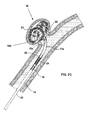
- the positioning system 10 of the illustrated embodiment is then inserted into the microcatheter 14 to position the implant interface 80 at the distal end of the positioner 40 near the target site 16, as illustrated in Fig. 2C .
- the implant 100 can be attached to the implant interface 80 prior to inserting the positioning system 10 into the microcatheter 14. This mode of implant delivery is illustrated in Figs. 2A-2C .
- the delivery of the implant 100 is facilitated by disposing the microcatheter marker 15a near the target site 16, and aligning the microcatheter marker 15 with a positioner marker 64 in the positioner 40 which, when the two markers (markers 15 and 64) are aligned with each other as illustrated in Fig. 2C , indicates to the operator that the implant interface 80 is in the proper position for the release of the implant 100 from the positioning system 10.
- the implant interface 80 is a portion of the positioning system 10 that allows the operator to mechanically control the engagement and disengagement of the implant 100 to the positioner 40, and allows the positioner 40 to retain the implant 100 in a way that minimally contacts the implant 100, that permits movement of the implant relative to the positioner in some or all of axial, tilt, and rotational directions, and that in some embodiments allows the implant 100 to move axially and without radial movement when engaging and disengaging the implant interface 80.
- the implant interface 80 provides mechanical control of the engagement and disengagement of the implant 100 by retaining a member engaging the implant 100.
- this member is a securing member 94 that is coupled at its proximal end to the distal tip 88 of an elongate member 52 such as shown in Figs. 3-4 .
- the securing member 94 is also coupled to a structure such as embolic coil 90 at its distal portion.
- the elongate member 52 is disposed in the cavity 86 that is defined by the distal surface 72 of the stopper 70, the proximal surface 83 of the end cap 82, and the inner walls of the positioner tube 42.
- a positioner tube sleeve 66 encloses the positioner tube 42 to provide a sliding exterior surface to the positioner tube 42 that facilitates the insertion and sliding of the positioner tube 42 into and through the microcatheter 14 ( Figs. 2A-2C ).
- the distal end of the cavity 86 terminates at an end cap 82 which has a port 84 for communicating with the distal exterior environment.
- the implant interface 80 may also include an enlarged portion 96 and a stop element 85.
- An implant may be any implant that can be retained and positioned by a positioning system (e.g., a catheter delivery system). Suitable examples of implants include, but are not limited to, stents, filters, dilation balloons, thrombectomy devices, atherectomy devices, flow restoration devices, embolic coils, embolic protection devices, etc.
- the implant 100 is depicted with the coil 90 being retained by the implant interface 80 by an extension (e.g., securing member 94) that engages or is coupled to the coil 90.
- the extension can be a part of the implant 100 when the implant 100 is made, a modified portion of the manufactured implant 100, or attached to the implant 100 after initial manufacturing.
- the implant 100 is depicted as comprising an embolic coil 90.
- Figs. 1A-1B shows the coil 90 in a coiled orientation prior to insertion into the microcatheter 14.
- the implant 100 shown in Figs. 2B-9A , 10-13A, and 14 is in a truncated form and disposed in alignment with the axis and the interior of the microcatheter (not shown).
- the implant 100 shown in Fig. 2C is shown in an implanted state, disposed in an aneurysm.
- the implant 100 may comprise (i) a coil 90 having a proximal portion and a distal portion; (ii) a stretch-resistant member 112 extending through the coil 90 and having a proximal end and a distal end, the stretch-resistant member 112 distal end coupled to the coil 90 distal portion; (iii) a reduced dimension proximal portion which may be a crimped portion 116 of a coil shell 118 disposed at the proximal end of the stretch-resistant member 112, and which can be otherwise free of the proximal portion of the coil 90.
- the crimped portion 116 may be welded to the proximal portion of the coil 90.
- the crimped portion 116 with a reduced dimension, and the coil 90 may be free to rotate around the central axis of the implant 100 as facilitated by the illustrated embodiments.
- the distal portion of the stretch-resistant member 112 extends through the coil lumen 105 defined by the coil 90 and is coupled to coil 90 at the distal end (e.g., by a polymer melt 114), which allows the coil 90 have free rotation about a longitudinal axis.
- the implant or a portion of the implant may be firmly held by the delivery system and is not free to rotate and, when the implant and delivery system are advanced distally to the target site through a microcatheter, the surface of the implant (especially the helical surface of some coils) can induce a torque within the implant when moved along the lumen of a microcatheter. That torque is stored as a potential energy in a compressed spring within the implant itself and within the connection between the implant and the delivery system. When the implant 100 then emerges from the microcatheter 14 at the target site, it is believed that the potential energy can be released suddenly and cause the implant to twist unpredictably and deposit itself in an undesirable location.
- the positioning system 10 facilitates the unhindered rotation of the crimped portion 116 and coil 90, thereby avoiding this problem that exists with some delivery systems.
- the free rotation of the coil 90 and crimped portion 116 allows the implant 100 to be deployed from the microcatheter 14 at the target site 16 much more gently than with some systems having a connection that is rigid or that partly or wholly limits movement and rotation between the implant and delivery system, and the free rotation also lowers the force applied to the vasculature during deployment and positioning of the implant 100 at the target site 16.
- embolic coils suitable for use with the positioning system 10 include the Sapphire TM , Axium TM , NXT TM , and Nexus TM embolic coils, commercially available from EV3, Inc. of Madison, Minnesota USA.
- the implant 100 of the illustrated embodiment comprises an embolic coil
- the implant 100 may be any implant that can be inserted with a catheter, such as a stent, a filter, a dilation balloon, a thrombectomy device, an atherectomy device, a flow restoration device, an embolic coil, or an embolic protection device.
- stents suitable for use with the delivery system 10 include the IntraStent®, ParaMount TM , PRIMUS TM , PROTÉGÉ®, and Solitaire TM stents, commercially available from EV3, Inc. of Madison, Minnesota USA.
- a commercially available embolic protection device suitable for use with the delivery system 10 is the SpideRX® embolic protection device, commercially available from EV3, Inc. of Madison, Minnesota USA.
- the positioner 40 provides the operator the ability to move the implant 100 controllably through the microcatheter 14 and to position the implant properly at the target site 16.
- the positioner 40 provides a mechanical system for selectively engaging the implant 100, while maintaining a narrow profile and sufficient flexibility to navigate the tortuous pathways within the body to reach the target site 16. While providing a small and flexible profile, the positioner 40 has sufficient strength to allow the operator to controllably move the implant 100 through the microcatheter 14, and the mechanical engagement with the implant 100 remains functional and controllable when subjected to high tortuosity near the target site 16.
- the mechanical engagement of the positioner 40 to the implant 100 also maintains the proper orientation of the implant 100 throughout the positioning procedure by allowing the implant 100 to rotate and discharge any torsional forces induced during the movement of the implant 100 to the target site 16.
- the positioner 40 also allows the operator to control the movement of the positioner 40 and implant 100 by properly translating the control exerted by the operator into predictable and responsive movements near the target site 16.
- the actuator interface 80 provides the operator the ability to control the movement of the implant 100 as it is positioned by the positioning system 10, and to mechanically control the selective engagement and disengagement of the implant 100 and implant interface 80.
- the actuator interface 80 controls the movement of the implant 100 by providing a surface upon which the operator can exert control, so that the controlling motions of the operator are accurately transferred to the implant interface 80 and implant 100 through the positioner 40.
- the actuator 20 provides a mechanism that removably engages the actuator interface 80 and causes the controllable and predictable movement of the actuator interface 80.
- the actuator 20 also provides a design that allows the operator to hold the actuator 20 firmly in place, in order to maintain the position of the positioner 40 relative to the target site 16, and allows the operator to utilize the actuator 20 in a controlled manner that minimizes the movement of the positioner 40.
- the proximal portion (e.g., enlarged portion 96, etc.) of the implant 100 is generally designed to be complementary to the distal portion (e.g., end cap 82, port 84, etc.) of the tubular member (e.g., positioner tube 42, catheter, etc.).
- the implant 100 Prior to the delivery of the implant 100 to the target site 16, the implant 100 may be coupled, either directly or indirectly, to the implant interface 80.
- Figs. 3-14 show closer views of various exemplary embodiments of the implant interface 80 and mechanisms for detaching the implant 100 from the implant interface 80. While the various exemplary embodiments include the delivery of coil implants, any compatible implants may be used in accordance with the embodiments described herein.
- Figs. 3-14 show various exemplary assemblies for deploying an implant 100 in a vasculature.
- the assembly may include a tubular member (e.g., position tube 42) defining a member lumen (e.g., cavity 86) within the tubular member and further defining an opening (e.g., port 84) at the distal portion (e.g., end cap 82) of the tubular member.
- One or more of the assemblies may further include an implant 100 extending distally from the positioner tube 42 and an elongate member 52 moveably disposed within the positioner tube 42.
- the implant 100 is configured for placement into an aneurysm or other treatment site within a patient.
- the implant 100 may include an embolic coil 90 formed by a wire, filament, or other elongate member helically-wrapped about a central axis to form a generally tubular structure. As shown in Fig. 14 , the coil 90 may define a lumen 105 therein which extends axially along the length of the coil 90.
- the implant 100 may further include an enlarged portion 96 coupled to or otherwise forming an integral part of the securing member 94, which extends into the lumen 105 and is coupled to or otherwise forms an integral part of the implant 100 (e.g., coil 90).
- the coil 90 may be coupled to the distal region of the securing member 94, which extends through the coil lumen 105.
- the enlarged portion 96 may be positioned within the cavity 86 proximal to the opening (e.g., port 84). In certain embodiments, however, the enlarged portion 96 may be positioned outside the cavity 86, as illustrated, distal to the opening. In some embodiments, the enlarged portion 96 may be larger than the opening. In some embodiments, the enlarged portion 96 may be smaller than the opening.
- the elongate member 52 extends within the tubular member lumen. In some embodiments, the elongate member 52 extends distally through the port 84. In some embodiments, the elongate member 52 may be coupled to the enlarged portion 96. In some embodiments, the elongate member 52 has a distal segment 88 that extends past the enlarged portion 96. In some embodiments, the elongate member 52 contacts the distal-facing surface 130 ( Fig. 7-10 ) of the enlarged portion 96 thereby retaining the enlarged portion 96. In some embodiments, the elongate member 52 has an expandable body 140 ( Fig. 12 ). In some embodiments, the expandable body 140 may be expanded distally to the enlarged portion 96 thereby retaining the enlarged portion 96. In some embodiments, the elongate member 52 is positioned at least partially distal to the enlarged portion 96.
- Figs. 3-5 , 7-10, 12, and 14 relate to embodiments that detach or release the implant 100 through a proximal motion of the elongate member 52.
- This proximal motion may be achieved by, for example, pulling proximally on the elongate member 52 with respect to the tubular member or pushing on the tubular member such that the tubular member moves distally with respect to the elongate member 52 or both.
- Figs. 6 and 11 relate to embodiments that detach or release the implant 100 by a distal translation of the elongate member 52.
- This distal translation may be achieved by, for example, pushing the distal portion 88 of the elongate member 52 such that elongate member 52 moves distally with respect to the tubular member or pulling on the tubular member such that the tubular member moves proximally with respect to the elongate member 52 or both.
- the implant interface 80 includes a cavity 86 defined at least in part by a tubular member, a positioner tube 42, an end cap 82, a stopper 70, an elongate member 52 and its distal portion 88, a positioner tube sleeve 66, and a stop element 85.
- the positioner tube 42, the end cap 82, and the distal facing wall 72 of the stopper 70 define a cavity 86 within the implant interface 80.
- the stopper 70 can function to guide and control the movement of the distal portion 88 of the elongate member 52.
- the positioner tube 42 is made from a material that is flexible and strong enough to transfer forces applied by the operator (e.g., a surgeon) at the proximal end to the implant interface 80.
- Suitable examples of materials include, but are not limited to, 304 stainless steel hypotube, polymeric extrusion, braided extrusion, or engineering polymer materials (e.g., polyether ether ketones (PEEK), polyimide, nylon, polyester, etc.) that can have about 0.010 to about 0.018 inch outer diameter and about 0.005 to about 0.012 inch inner diameter, with about 10 to about 60 cm length of the distal end of the positioner tube 42 ground to about 0.008 to about 0.016 inch outer diameter to reduce girth and increase flexibility.
- PEEK polyether ether ketones
- the positioner tube 42 may be comprised of slots, holes, laser cuts, or other structures to provide flexibility to portions of or all of the positioner tube 42. As will be appreciated, the dimensions and/or materials of the positioner tube 42 may vary without departing from the scope of the disclosure.
- the end cap 82 is made of about 0.001 to about 0.005 inch thick 304 stainless steel, a polymeric material, or a steel alloy retainer ring with about 0.008 to about 0.018 inch outer diameter and about 0.003 to about 0.009 inch diameter port welded or bonded to the distal end of the positioner tube 42.
- the dimensions and/or materials of the end cap 82 may vary without departing from the scope of the disclosure.
- the stopper 70 is made of 304 stainless steel, a platinum alloy, a polymeric extrusion, a braided extrusion, or a non-elongating polymeric material with about 0.001 to about 0.012 inch inner diameter, and is coupled (e.g., welded or glued) to the interior of the positioner tube 42.
- the dimensions and/or materials of the stopper 70 may also vary, without departing from the scope of the disclosure.
- the elongate member 52 is a cord, a wire, a rod, a tubular, a thread or a filament made of a metal or a polymer.
- the cross-section of the elongate member 52 may be circular. In certain embodiments, however, the cross-section may be other shapes, such as polygonal, without departing from the scope of the disclosure.
- the elongate member 52 has an outer diameter from about 0.001 to about 0.005 inch, but the outer diameter may vary, depending on the application.
- the positioner tube sleeve 66 may encase or generally surround the longitudinal length of the positioner tube 42, thereby providing a sliding engagement between the positioner tube 42 and the positioner tube sleeve 66.
- the sliding engagement may facilitate the insertion and sliding of the positioner tube 42 into and through the microcatheter 14 ( Figs. 2A-2C ).
- the positioner tube sleeve 66 may be configured to increase the lubricity between the positioner tube 42 and the inner lumen surface of the microcatheter 14 and to further increase the structural integrity of the positioner tube 42.
- the enlarged portion 96 may be coupled to the proximal end of the securing member 94, which is attached to the coil 90 at the proximal end of the coil 90 and positioned distal to the port 84.
- the enlarged portion 96 has a cross-sectional area that is greater than a cross-sectional area of the port 84, which prevents the enlarged portion 96 from passing therethrough, and thereby prevents the coil 90 from coming into contact with the end cap 82.
- a stop member 85 may also be disposed within the cavity 86 and coupled to or otherwise formed integrally with the elongate member 52.
- the stop element 85 also has a cross-sectional area that is greater than the cross-sectional area of the port 84.
- the stop member 85 and the enlarged portion 96 limit the range of axial motion possible for the implant 100 to traverse while engaged at the implant interface 80, which in turn may be advantageous for greater accuracy and faster positioning of the implant 100 in the target site 16 ( Fig. 2A ).
- the implant interface 80 and the implant 100 may be directly coupled to the elongate member 52 so that any longitudinal translation of the elongate member 52 corresponds to a similar or same translation of the securing member 94.
- the implant 100 shown in Fig. 3 may be detached from the positioning system 10 according to at least the following embodiments.
- a proximal motion of the elongate member 52 can cause the enlarged portion 96 to come in contact with the end cap 82.
- This proximal motion can be achieved by any number of ways including pulling of the elongate member 52 away from the target site or pushing of the positioner tube 42 towards the target site or a combination of both.
- the proximal motion is caused by an actuator positioned at the proximal portion of the positioning system 10.
- a longitudinal force applied proximally along the axis of the elongate member 52 can contribute to the release or the detachment of the implant 100.
- the securing member 94 can break so as to detachably release the implant 100 from the positioning system 10.
- at least one of the enlarged portion 96, securing member 94, and the elongate member 52 can break so as to detachably release the implant 100.
- the breakage occurs at a structurally weak spot such as, but not limited to, an etched, crimped, reduced diameter, annealed, or notched spot.
- at least one of the securing member 94 and the elongate member 52 is made from a frangible material so that it tends to break up into, for example, two pieces rather than deforming plastically and retaining its cohesion as a single object.
- frangible materials include, but not limited to, aluminum oxide, silicon dioxide, magnesium oxide, zirconia, cordierite, silicon carbide and the like.
- the proximal portion of the elongate member and/or securing member 94 is frangible so that any breaking is localized to those portions.
- at least one of the securing member 94 and the elongate member 52 may be configured to break inside the enlarged portion 96.
- the distal portion 88 of elongate member 52 may break to release the implant 100.
- the enlarged portion 96 may break to release the implant 100.
- the stop element 85 may break to release the implant 100.
- the surfaces at or near the proximal portion of the securing member 94 and/or inner walls defined by a recess 125 of the enlarged portion 96 may have a topography that enhances frictional contact.
- the recess 125 is generally designed to receive and frictionally engage the securing member 94 through contact.
- the securing member 94 and inner walls of the enlarged portion 96 may have periodic gratings that provide frictional contact with each other.
- the inner walls of the enlarged portion 96 and/or the distal portion of the securing member 94 may be made from a material that has a relatively high frictional coefficient or have surfaces that are coarse.
- securing member 94, elongate member 52, or both may be secured to the enlarged portion 96 by compressing the enlarged portion 96 onto the securing member 94 and the elongate member 52. This may be accomplished by swaging, crimping, pressing, casting the enlarged portion 96 onto the securing member 94 and elongate member 52, by adhering enlarged portion 96 onto the securing member 94 and elongate member 52, or by other means.
- the elongate member 52 extends distally through the port 84 and terminates outside the port 84.
- the securing member 94 is coupled to the distal portion 88 of the elongate member 52 through frictional contact with the enlarged portion 96.
- the proximal end of the securing member 94 is disposed in the enlarged portion 96 and making frictional contact with inner walls of the recess 125 within the enlarged portion 96.
- a proximal motion of the elongate member 52 will cause the enlarged portion 96 to come in contact with the end cap 82.
- a proximal force will cause the distal portion 88 of the elongate member 52 to disengage from the enlarged portion 96.
- the proximal force causes the distal portion 88 of the elongate member 52 to disengage from the stop element 85.
- a force applied proximally on the enlarged portion 96 is greater than the frictional force between the securing member 94 and the enlarged portion 96, the securing member 94 will disengage from the enlarged portion 96 and thereby detach the implant 100 from the positioning system 10.
- the proximal portion of the securing member 94 may be engaged with the enlarged portion 96 that is coupled to an elongate member 52 that is at least partially disposed within the cavity 86 and extends distally through the port 84.
- an obstructed portion 150 of elongate member 52 extends distally past the enlarged portion 96.
- This curved profile of the obstructed portion 150 increases the detach force required for the release of the implant 100 as compared to a non-undulating profile.
- the curved profile may be any shape that obstructs the release of the curved portion 150.
- Suitable shapes include, but are not limited to, crimped shape, S-shape, O-shape, and the like.
- the curved profile may have multiple peaks or an undulating profile (e.g., sinusoidal shape, helical, etc.).
- a proximal motion of the elongate member 52 may cause the enlarged portion 96 to engage the end cap 82. If the force applied proximally on the elongated member 52 is greater than the detach force, the crimped portion 150 of the elongated member 52 will at least partially straighten and release from the enlarged portion 96, thereby detaching the implant 100 from the positioning system 10. In some embodiments, the crimped portion 150 of the elongated member 52 will be released from the enlarged portion 96 by sliding through an aperture in the enlarged portion 96.
- the proximal portion of the securing member 94 is coupled to the stop element 85 and the enlarged portion 96.
- the enlarged portion 96 is disposed in the cavity 86 proximal to the port 84 while the stop element 85 is positioned distal to the port 84 and proximal to the coil 90.
- This embodiment also includes a pusher 160 that is part of the distal portion 88 of the elongate member 52.
- the enlarged portion 96 has a cross-section that is generally larger than the cross-section of the port 84 so that the enlarged portion 96 is prevented or hindered from passing through the port 84.
- the end cap 82 may be a retaining ring that is made from a radially expandable material.
- a radially expandable material that is compatible with one or more embodiments may be used.
- expandable materials may include, but are not limited to, silicone, thermoplastic elastomers, rubbers, metals, nickel-titanium alloys, polymers (e.g., polytetrafluoroethylene (PTFE), polyethylene terephthalate (PET), polyether ether ketones (PEEK)), etc.
- the pusher 160 may generally be used to apply a longitudinal force that causes a distal motion of the enlarged portion 96.
- This longitudinal force can cause the enlarged portion 96 to come into contact with the radially expandable end cap 82. Given a sufficient force, the enlarged portion 96 can engage the end cap 82 to forcibly expand the end cap 82 and allow the enlarged portion 96 to pass through port 84.
- the enlarged portion 96 may be made from a deformable material. Given a sufficient longitudinal force that acts distally, the enlarged portion 96 can deform while engaging the end cap 82 to allow the enlarged portion 96 to pass through.
- any deformable material that is compatible with one or more embodiments may be used. Suitable examples of deformable materials may include, but are not limited to, silicone, thermoplastic elastomers, biopolymers, rubbers, metals, nickel titanium alloys, etc.
- the enlarged portion 96 is disposed in the positioner tube 42 and coupled to a distal segment 88 of the elongated member 52 that at least partially extends around the enlarged portion 96.
- the coupling between the enlarged portion 96 and distal portion 88 of the elongate member 52 may be achieved through a ball and socket connection ( Fig. 7-8 ), a ball and a curved wire connection ( Fig. 9A-9B ), a pivot and cam ( Fig. 10 ), a hinge joint, a pivot joint, and the like.
- the enlarged portion 96 which can be a ball, is disposed in the positioner tube 42 while positioned proximal to the port 84 and coupled to the proximal portion of the securing member 94.
- a stop element 85 is positioned distal to the port 84 and proximal to the coil 90. While the enlarged portion 96 is generally small enough to fit or pass through port 84, the stop element 85 is generally large enough to abut the port 84 when drawn proximally.
- the socket element 170 is coupled to the distal portion 88 of the elongated member 52 and disposed in the positioner tube 42. As shown in Figs. 7-8 , the socket element 170 is configured to at least partially envelope or contact the distal facing surface 130 of the enlarged portion 96, which at least partially helps to retain the enlarged portion 96.
- the socket element 170 may further include at least one spring loaded element (e.g., a leaf) that promotes release of the enlarged portion 96 upon a proximal pulling motion on the socket element 170.
- the proximal pulling motion may cause an elastic or plastic deformation of the socket element 170, which allows the release of the enlarged portion 96.
- the socket element 170 may generally be made from any material that is compatible with one or more embodiments.
- Suitable materials include, but are not limited to, alloys (e.g., nickel-titanium, titanium-palladium-nickel, Elgiloy, stainless steel, nickel-iron-zinc-aluminium, bronze, platinum alloys, titanium alloys, etc.), thermoplastics, metals (platinum, titanium, etc.), ceramics, etc.
- the socket element 170 may include a partially spherical recess defined by the socket and a slot (not shown) that extends through a portion of the recess.
- the enlarged portion 96 may be coupled to the socket element 170 by pivoting the elongated member 52, securing member 94, or both so that the securing member 94 may slide into the slot while the enlarged portion 96 is disposed inside the partially spherical recess. Once the enlarged portion 96 is secured inside the recess, the ball and socket connection may be straightened out so as to keep a narrow profile during insertion into a positioner tube 42.
- the enlarged portion 96 is disposed in the positioner tube 42 and coupled to a curved wire 180 positioned at a distal segment 88 of the elongated member 52.
- the distal end of the positioner tube includes an opening 240 that is larger than the enlarged portion 96.
- the curved wire 180 partially extends around distal facing surface 130 of the enlarged portion 96 to retain the enlarged portion 96 within the positioner tube 42.
- Fig. 9B shows an end view of the curved wire 180, which shows a slot 75 that runs transversely and is designed to receive a securing member 94.
- the curved wire 180 may generally be made from any material that is compatible with one or more embodiments.
- Suitable examples of materials include, but are not limited to, alloys (e.g., nickel-titanium, titanium-palladium-nickel, Elgiloy, stainless steel, nickel-iron-zinc-aluminium, bronze, platinum alloys, titanium alloys, etc.) and metals (platinum, titanium, etc.).
- alloys e.g., nickel-titanium, titanium-palladium-nickel, Elgiloy, stainless steel, nickel-iron-zinc-aluminium, bronze, platinum alloys, titanium alloys, etc.
- metals platinum, titanium, etc.
- the ball element 96 may be coupled to the curved wire element 180 by pivoting the elongated member 52, securing member 94, or both so that the securing member 94 may slide into the slot 75 while the ball element 96 is disposed inside the concave curvature defined by the curved wire 180. Once the ball element 96 is secured inside the concave curvature, the ball 96 and curved wire 180 connection may be straightened out as to keep a narrow profile during insertion into a positioner tube 42.
- the curved wire 180 may extend distal to the opening 240 while the securing member 94 is positioned in the slot 75 and the enlarged portion 96 is retained by the concave curvature of the curved wire 180. A proximal motion of the elongate member 52 would draw the retained assembly into the positioner tube 42.
- the implant 100 may be released by plastically or elastically deforming the curved wire 180. Such deformations may be achieved by pulling the elongate member 52 proximally with a sufficient force such that coil 90 abuts positioner tube 42, which allows the curved wire 180 to straighten as it is drawn proximally past the enlarged portion 96.
- the elongate member 94 may include a stop (not shown) similar to a stop element 85, which is placed proximal to the coil 90 and distal to the opening 240. The stop may be larger in size than the opening 240 and is able to abut edges of the opening 240 when the curved wire 180 is drawn proximally.
- the enlarged portion 96 is disposed in the positioner tube 42 and positioned proximal to the port 84.
- the enlarged portion 96 may be small enough to fit through port 84 or port 84 may be substantially same diameter of lumen of positioner tube 42.
- the enlarged portion 96 is attached to the proximal portion of the securing member 94 and further coupled to a pivot 190 and cam 200 element that is part of the distal portion of the elongated member 52.
- the elongated member 52 and the cam 200 are coupled at the rotatable pivot 190.
- the cam element 200 may be hemispherical or otherwise designed to partially receive the enlarged portion 96 therein.
- the cam element 200 and the pivot 190 may generally be made from any material that is compatible with one or more embodiments described herein. Suitable materials include, but are not limited to, alloys (e.g., nickel-titanium, titanium-palladium-nickel, Elgiloy, stainless steel, nickel-iron-zinc-aluminium, bronze, platinum alloys, titanium alloys, etc.), thermoplastics, metals (platinum, titanium, etc.), ceramics, etc.
- alloys e.g., nickel-titanium, titanium-palladium-nickel, Elgiloy, stainless steel, nickel-iron-zinc-aluminium, bronze, platinum alloys, titanium alloys, etc.
- thermoplastics e.g., metals (platinum, titanium, etc.), ceramics, etc.
- the cam 200 is positioned so that a portion of its concave surface is engaging the distal facing surface of the enlarged portion 96. This allows the cam to retain the enlarged portion 96 within the positioner tube 42 as needed.
- the cam 200 may further include a slot (not shown) for receiving and retaining the securing member 94.
- the port 84 is larger than the enlarged portion 96 so that the enlarged portion 96 is able to pass through the port 84 once the pivot cam releases the enlarged portion 96.
- the enlarged portion 96 is released from the cam 200 by drawing the elongate member 52 proximally until coil 90 contacts the end cap 82. Further proximal movement of the elongate member 52 causes the cam 200 to rotate about pivot 190, thereby disengaging the concave surface of the cam 200 from the distal surface of the enlarged portion 96 and freeing the enlarged portion 96 to travel distally thru the cavity 86 and out of the port 84.
- the port 84 is made from an expandable material and is smaller than the enlarged portion 96, as described above with respect to Fig. 6 , and the enlarged portion 96 passes through the smaller dimensioned port 84 by applying a force sufficient to expand the port 84.
- the enlarged portion 96 extends through the opening 240 and is disposed in the positioner tube 42.
- the opening 240 is larger than the enlarged portion 96.
- Fig. 11 shows a pre-detachment configuration in which the enlarged portion 96 is locked in place on one side by the edges of an aperture 115 (side window) defined in the wall of the positioner tube 42.
- An elastomeric padding 220 contacts the side of the enlarged portion 96 that is opposed to the aperture 115.
- the elastomeric padding 220 may generally be made from any material that is compatible with one or more embodiments.
- Suitable examples of materials include, but are not limited to, silicone, thermoplastic elastomers, rubbers, polymers (e.g., polytetrafluoroethylene (PTFE), polyethylene terephthalate (PET), polyether ether ketones (PEEK)), etc.
- PTFE polytetrafluoroethylene
- PET polyethylene terephthalate
- PEEK polyether ether ketones
- the distal portion of the elongated member 52 comprises pusher 160, which is configured to engage the enlarged portion 96 by distal movement of the elongated member 52.
- a ramp 230 may also be disposed inside the positioner tube 42 and acts to guide the pusher 160 to engage the enlarged portion 96 during the detachment of the implant 100.
- the implant 100 may be detached by pushing the pusher 160 against the enlarged portion 96, thereby causing the enlarged portion 96 to move distally within the positioner tube 42, compressing the elastomeric padding 220, and forcing the enlarged portion 96 distally out of the side window 115 and further distally out of the opening 240.
- the enlarged portion 96 extends through the opening 240 and is disposed in the positioner tube 42.
- the opening 240 is larger than the enlarged portion 96.
- Fig. 12 shows a pre-detachment configuration in which the enlarged portion 96 is coupled to the distal portion (compressed mesh 260) of the elongated member 52.
- the compressed mesh may be an expandable/compressible material that deformably locks the enlarged portion 96 inside the positioner tube 42 and proximal to the opening 240.
- Suitable examples of materials include, but are not limited to, woven or knitted metal wires comprised of, for example, Nitinol, stainless steel, Elgiloy, platinum alloys, titanium alloys, or other metals.
- the woven or knitted materials may also be comprised of, for example, polymers such as polypropene, polyethylene, polyethylene terephthalate (PET), or other materials.
- the mesh 260 can be a foam comprised of, for example, polymers such as silicone, polypropylene, polyethylene, nylon, etc. or an elastomeric solid comprised of silicone rubber, butyl rubber, polyurethane, or other materials.
- At least a portion of the enlarged portion 96 is in contact with a wall within the cavity 86, and at least a portion of compressed mesh is in contact with a wall within the cavity 86 and engages a distally facing surface of the enlarged portion 96.
- the implant 100 may be detached by pulling the elongate member 52 proximally, causing the compressed mesh 260 to move proximally in relation to the enlarged portion 96, and drawing the coil 90 against the opening 240.
- the coil 90 is larger than the opening 240, limiting further proximal movement of the coil 90.
- the more distal portions of the compressed mesh 260 become compressed as the compressed mesh 260 is drawn proximally past the enlarged portion 96. Once the compressed mesh 260 is entirely proximal to the enlarged portion 96, the enlarged portion 96 may move distally within the positioner tube 42 and out of the opening 240.
- the implant 100 includes an enlarged portion 96 that may have fins or fin-like structures (e.g., struts) that extend radially and transversely out from the central axis of the securing member 94.
- the fins or fin-like structures may generally be made from any material that is compatible with one or more embodiments of the subject technology. Suitable examples of materials include, but are not limited to, alloys (e.g., nickel-titanium, titanium-palladium-nickel, bronze, Elgiloy, stainless steel, titanium alloys, platinum alloys, etc.), metals (platinum, titanium, etc.), ceramics, etc.
- the fins or fin-like structures can also be comprised of, for example, polymers such as polypropene, polyethylene, polyethylene terephthalate (PET), or other materials. Additionally, the fins can be a foam comprised of, for example, polymers such as silicone, polypropylene, polyethylene, and nylon or an elastomeric solid comprised of silicone rubber, butyl rubber, polyurethane, or other materials.
- the cross-section of the enlarged portion 96 may have any shape such as, for example, a star ( Fig. 13B ).
- the distal portion 250 of the enlarged portion 96 may also have a distal curvature (e.g., convexity or a concavity, not shown). While not shown, this embodiment may interact with an implant interface 80 such as shown in Figs. 3-12 .
- the enlarged portion 96 may be disposed in the positioner tube 42 through a port 84 that is smaller than the enlarged portion.
- the cross-section of the port 84 of the end cap 82 can be non-circular or have a shape that is complementary to the enlarged portion 96 (e.g., Fig. 13B ).
- detachment of the implant 100 may generally be accomplished by rotating the enlarged portion 96 to fit through the similarly shaped port 84 as by a "lock and key" mechanism.
- the distal portion of the elongate member 52 extends past the port 84 and is disposed inside the implant coil lumen 105 where it is coupled to the coil lumen extending portion 112 of the securing member via a straight release mechanism.
- the distal portion of the elongate member 52 engages an eyelet 110, or a portion thereof, that forms the proximal portion of the securing member 112.
- the distal portion of the elongate member 52 preferably terminates proximal to the eyelet 110, the distal portion forming a straight member.
- the coil may be crimped about the straight member to frictionally retain the straight member inside the coil shell 116.
- the coil is swaged or otherwise plastically deformed about the straight member. Further, as shown in Fig. 14 , a portion of the coil shell that is just distal to the port 84 is crimped around the portion of the elongate member 52 that is just proximal to the eyelet and just distal to the port 84. The crimped portion of the coil shell is severed from the rest of the coil shell 118.
- the crimped portion of the coil shell 116 is welded to the rest of the coil shell 118.
- the eyelet 110 may be separate and distinct from the elongate member 52.
- the elongate member 52 may be frictionally retained within lumen of crimped potion 116. Proximally drawing the elongate member 52 liberates the elongate member 52 from lumen of the crimped portion 116.
- the eyelet 110 is attached or coupled to the crimped portion 116 by, for example, welding, adhesives, friction, etc.
- a stop element 85 may be added to the elongate member 52 proximal to the port 84.
- the elongate member 52 is coupled to the eyelet 110 by means of a line of weakness that separates when the elongate member 52 is pulled proximally, using means similar to those embodiments shown and/or described for Fig. 3 .
- FIGs. 3-14 disclose specific embodiments, some or all of the features of the embodiments described herein may be used interchangeably or in combination with each other or with other embodiments.
- Suitable implants include, but are not limited to, stents, filters, dilation balloons, thrombectomy devices, atherectomy devices, flow restoration devices, embolic coils, embolic protection devices, or other devices, and the like.
- the method includes: advancing in a vasculature, an assembly according to any of the embodiments described herein; and detaching the implant.
- the assembly includes a tubular member (e.g., a catheter), a implant 100 configured for placement into an aneurysm, an enlarged portion 96, and an elongate member 52.
- a tubular member e.g., a catheter
- implant 100 configured for placement into an aneurysm
- enlarged portion 96 configured for placement into an aneurysm
- elongate member 52 configured for placement into an aneurysm
- the detachment of the implant 100 is achieved by withdrawing the elongate member 52 proximally relative to the tubular member, thereby separating the enlarged portion 96 from the elongate member 52 at the enlarged portion 96, to release the coil 90 at an aneurysm.
- the separating occurs at a location within the enlarged portion 96. In some embodiments, the separating includes breaking the elongate member 52. In some embodiments, the separating includes breaking the elongate member 52 within the enlarged portion. In some embodiments, the separating includes pulling the elongate member 52 from within the enlarged portion 96
- the separating occurs when a force applied to the elongate member 52 during the proximal movement exceeds a force maintaining a frictional coupling between the elongate member 52 and the enlarged portion 96. In some embodiments, the separating comprises withdrawing a distal segment of the elongate member through the enlarged portion, the segment having a curved profile. In some embodiments, the curved profile is a wave.
- the method includes: positioning in a vasculature, an assembly according to any of the embodiments described herein; and detaching the implant.
- the assembly includes a tubular member, an implant 100, an enlarged portion 96 positioned in the member lumen proximal to the opening, and an elongate member 52.
- the detachment of the implant 100 is achieved by moving the elongate member 52 proximally relative to the tubular member to deform a distal segment of the elongate member 52, thereby releasing the enlarged portion 96 from the member lumen.
- the implant 100 may be detached from a tubular member (e.g., positioning system 10) by pulling proximally a longitudinal member (e.g., an elongate member 52) that includes an enlarged portion 96 positioned outside the tubular member and a stop element 85 positioned inside the tubular member, the longitudinal member being coupled to the implant 100.
- the longitudinal member is pulled proximally with a force sufficient to break the member to release the implant 100.
- the implant 100 is detached by pushing the tubular member (e.g., positioning system 10 or positioner 10) distally.
- the tubular member's distal end preferably contacts an enlarged portion 96 (coupled to the implant 100), and the tubular member is pushed distally relative to the elongate member 52 with a force sufficient to break the member, thereby releasing the implant 100.
- the implant 100 may also include a stop element 85 (positioned inside the tubular member) that limits distal advancement of the longitudinal member as the stop element 85 contacts the end cap 82.
- the stop element 85 on the longitudinal member absorbs forces (e.g., inadvertent longitudinal advancement or vibrations) that may be transferred to the implant 100 via the longitudinal member.
- the implant 100 may be detached from a tubular member (e.g., positioning system 10) by (i) coupling a longitudinal member that extends through a tubular member with an enlarged portion 96 that is frictionally coupled to an implant 100 and (ii) pulling the longitudinal member proximally with a force sufficient to overcome the frictional coupling.
- the implant 100 is detached from a tubular member (e.g., positioning system 10) by pushing the tubular member relative to the longitudinal member or elongate member 52 with a force sufficient to overcome the frictional coupling.
- the implant 100 may be detached from a frictional coupling between a longitudinal member and an enlarged portion 96 of the implant 100 by pulling the longitudinal member proximally with a force sufficient to overcome the frictional coupling.
- the implant 100 is detached from a tubular member (e.g., positioning system 10) by pushing the tubular member relative to the longitudinal member with a force sufficient to overcome the obstruction.
- a force sufficient to overcome the obstruction will conformationally change (e.g., straighten) the wavy or helical shape of the member extending distal to the enlarged portion 96.
- the force is sufficient to conformationally change the shape of the member and overcome any frictional coupling between the longitudinal member and the enlarged portion 96.
- the implant 100 may be detached from the tubular member (e.g., positioning system 10) by using a pusher to apply a force distally on the enlarged portion 96 with a sufficient longitudinal force so that the enlarged portion 96 may be pushed through the expandable retaining ring (e.g., end cap 82).
- the sufficient longitudinal force will increase the cross-section of the port 84 to permit the enlarged portion 96 to pass therethrough.
- the implant 100 may be generally detached from a tubular member (e.g., positioning system 10) by withdrawing in a proximal direction the ball and socket connection once the implant 100 is ready to be deployed.
- the socket may be elastically or plastically deformed to allow the enlarged portion 96 to be withdrawn.
- the stop element or the coil will abut the distal end of the catheter to limit proximal withdrawal and further withdrawal to cause the socket to change shape, thus allowing the enlarged portion 96 to be released.
- the ball and socket connection may be pivoted as to allow the free release of the implant 100.
- the enlarged portion 96 may be smaller than the port 84.
- the enlarged portion 96 may be larger than the port 84, which is expandable. In order to release the enlarged portion 96 from the smaller dimensioned port 84, a force sufficient to expand the port 84 as to allow the enlarged portion 96 to pass through is required.
- the implant 100 may be detached from a tubular member (e.g., positioning system 10) by pivoting the ball and curved wire connection once the implant 100 is ready to be deployed.
- the enlarged portion 96 has a cross-sectional size that is less than a cross-sectional area of the opening at the distal end of the tubular member. This allows the enlarged portion 96 to pass freely through the port 84 when the implant 100 is disengaged.
- the enlarged portion 96 may be larger than the opening, which is made of an expandable material. In order to release the enlarged portion 96 from the smaller dimensioned port 84, a force sufficient to expand the port 84 may be applied to allow the enlarged portion 96 to pass through.
- the implant 100 may be detached from a tubular member (e.g., positioning system 10) by pulling proximally the elongated member 52 so that the cam 200 rotates about the pivot 190 to allow the enlarged portion 96 to release freely.
- the cam 200 elastically or plastically deforms to release the enlarged portion 96.
- the implant 100 may be detached by applying a sufficient pushing force distally onto the enlarged portion 96 by the pusher 160 as to further deform elastomeric padding and allow the enlarged portion 96 to disengage from the aperture 115 and to advance past the opening 240.
- the implant 100 may be detached from a tubular member (e.g., positioning system 10) by pulling the elongated member 52 proximally so that the distal portion of the elongated member 52 slides against at least a portion of the enlarged portion 96. This sliding action causes the distal portions of the compressed mesh 140 to deform as to allow the enlarged portion 96 to be released and pass through the opening 240.
- a tubular member e.g., positioning system 10
- Figs. 13A-13B these may be used in conjunction with a suitable implant interface 80 such as shown in, for example, Fig. 3 .
- the implant 100 may generally be detached by applying a distal force sufficiently to the enlarged portion 96 (e.g. by a pusher shown in Fig. 6 ) such that the distal curvature 250 of the enlarged portion 96 may interact with end cap 82 and deform as to allow the enlarged portion 96 to pass through the port 84.
- the enlarged portion 96 may have a non-circular cross-section.
- the port 84 may also have a non-circular cross-section that is complementary to the cross-section of the enlarged-portion 96. In such cases, the enlarged portion 96 can be rotated (or the tubular member is rotated) so that the enlarged portion 96 may fit through the port 84 to release the implant 100.
- the implant 100 may be detached by pulling the elongate member 52 proximally at a sufficient force to overcome the frictional resistance of the crimped connection thereby detaching the implant 100.
- the method includes plastically deforming a proximal portion of a coil implant onto an elongate member to create a friction coupling between the proximal portion and the elongate member.
- the proximal portion is positioned distal to an opening at a distal end portion of a tubular member through which the elongate member extends.
- the deforming is achieved by crimping or swaging.
- the method includes forming a joint between a proximal portion of a coil implant and an elongate member such that a tensile strength of the joint is less than a tensile strength of the proximal portion and a tensile strength of the elongate member.
- the coupling proximal portion is preferably positioned distal to an opening at a distal end portion of a tubular member through which the elongate member extends.
- the forming is achieved by welding or soldering.
- top should be understood as referring to an arbitrary frame of reference, rather than to the ordinary gravitational frame of reference.
- a top surface, a bottom surface, a front surface, and a rear surface may extend upwardly, downwardly, diagonally, or horizontally in a gravitational frame of reference.
Abstract
Description
- The subject technology relates to therapeutic implant delivery systems and, more particularly, to a system that positions, deploys, and detaches an implant at a target location inside a body.
- Sometimes a body cavity, such as an aneurysm, is located in a surgically remote and delicate region, such as within the tortuous cerebral vasculature, that requires a specialized delivery system to navigate to the region and safely and reliably deliver and deploy an implant.
- Medical implants are important for their therapeutic and/or intervening roles in patients suffering from various ailments. For example, inferior vena cava filters may be implanted into the inferior vena cava to prevent fatal pulmonary emboli. Dilation balloons may be used during angioplasty procedures in order to widen the vessel and provide structural support.
- While there are many known implant detach mechanisms such as electrolytic separation, hydraulic delivery, and interference wire, these systems and methods often suffer from some reliability (e.g., false positive detachments) and/or performance issues (e.g., rigid profiles that are difficult to push).
- Therefore, there is a need to provide alternative implant delivery systems and methods that are reliable and overcome existing performance issues.
- Although at least some embodiments are described herein with respect to embolic coils, the subject technology may be used to position and delivery a wide variety of medical devices, such as stents, filters, dilation balloons, thrombectomy devices, atherectomy devices, flow restoration devices, embolic coils, embolic protection devices, or other devices to sites within the body.
- In clinical situations it may be desirable to occlude blood vessels for various reasons, such as the control or prevention of bleeding, the prevention of blood supply to tumors, treatment of arterial venous malformations (AVMs), and the blocking of blood flow within an aneurysm. Embolization of blood vessels has been performed by employing certain polymer compositions, particulates, and/or sclerosing material including silicone balloons, metallic coils, PVA particles, gelatin, alcohol, and the like, selectively to block blood flow in the blood vessels.
- Intracranial aneurysms are abnormal blood-filled dilations of a blood vessel wall that may rupture, causing significant bleeding and damage to surrounding brain tissue or death. In some cases, intracranial aneurysms can be surgically clipped to reduce the risk of rupture by placing a metal clip around the neck of the aneurysm to cut off and prevent further blood flow to the aneurysm. Many aneurysms cannot be treated surgically because of either the location and configuration of the aneurysm or because the condition of the patient does not permit intracranial surgery.
- Aneurysms may also be treated endovascularly, e.g., with embolic coils. The coils are placed in the aneurysm by extending a catheter endovascularly to the site of the aneurysm and passing single or often multiple metallic coils such as platinum, stainless steel, or tungsten coils through the catheter into the aneurysm. The coils placed within the aneurysm cause a thrombus to form in the vicinity of the coil which occludes the aneurysm and prevents further blood flow to the aneurysm. The treatment of intracranial aneurysms with coils isolates the aneurysm from arterial circulation, helping to guard against rupture and further growth of the aneurysm.
- The subject technology is illustrated, for example, according to various aspects described below. Various examples of aspects of the subject technology are described as embodiments. These are provided as examples and do not limit the subject technology. It is noted that these embodiments may be combined in any combination. In some embodiments, an assembly for deploying an implant into an aneurysm, comprises: a tubular member having (a) a member lumen in the tubular member and (b) an opening at a distal end portion of the tubular member; a coil implant configured for placement into an aneurysm and having (a) a coil; (b) a coil lumen extending longitudinally within the coil; and (c) a securing member (i) extending within the coil lumen, (ii) coupled, at a distal region of the securing member, to the coil, and (iii) having an enlarged proximal portion larger than, and positioned distal to, the opening; and an elongate member extending in the member lumen, through the opening, and coupled to the enlarged portion; wherein proximal movement of the elongate member relative to the distal end portion results in the enlarged portion contacting the distal end portion and separating from the elongate member.
- In some embodiments, the enlarged portion is substantially spherical.
- In some embodiments, the separating of the enlarged portion from the elongate member occurs at a location within the enlarged portion. In some embodiments, the separating comprises breaking the elongate member. In certain embodiments, the separating comprises breaking the elongate member at the location.
- In some embodiments, the assembly further comprises a stop element, coupled to the elongate member and residing in the member lumen, the stop element contacting the distal end portion upon distal movement of the elongate member relative to the tubular member. In certain embodiments, the stop element is larger than the opening. In certain embodiments, the stop element is substantially spherical.
- Some embodiments provide a frictional coupling between the elongate member and the enlarged portion. In some embodiments, separation between the elongate member and the enlarged portion occurs when a force applied to the elongate member during the proximal movement exceeds a force maintaining the frictional coupling. In some embodiments, the separating comprises sliding the elongate member out of the enlarged portion. In certain embodiments, the sliding comprises sliding the elongate member out of an aperture in the enlarged portion.
- In some embodiments, the elongate member extends distally beyond the enlarged portion. In some embodiments, the elongate member extends through the enlarged portion. In certain embodiments, the elongate member, distal to the enlarged portion, has an undulating profile. In certain embodiments, the elongate member, distal to the enlarged portion, has a profile having a pattern of peaks. In certain embodiments, the elongate member, distal to the enlarged portion, extends helically.
- In some embodiments, the elongate member has (i) a frictional coupling with the enlarged portion and (ii) an undulating profile distal to the enlarged portion. In some embodiments, the elongate member, distal to the enlarged portion, comprises a shape memory material.
- In some embodiments, the separating occurs when a force of the proximal movement exceeds both (a) a force maintaining the frictional coupling and (b) a force required to change the undulating profile as the elongate member is drawn proximally past the enlarged portion.
- In some embodiments, the enlarged portion comprises a proximal coil portion having a proximal lumen, and the elongate member extends through the proximal lumen. In certain embodiments, the coil portion is crimped on the elongate member, forming a frictional coupling between the coil portion and the elongate member. In certain embodiments, the separating occurs when a force applied to the elongate member during the proximal movement exceeds a force maintaining the frictional coupling.
- Some embodiments provide a method for deploying an implant into an aneurysm, comprising: advancing in a patient's vasculature: (i) a tubular member comprising (a) a member lumen in the tubular member and (b) an opening at a distal end portion of the tubular member; (ii) a coil implant configured for placement into an aneurysm and comprising (a) a coil; (b) a coil lumen extending longitudinally within the coil; and (c) a securing member (i) extending within the coil lumen, (ii) coupled, at a distal region of the securing member, to the coil, and (iii) having an enlarged proximal portion larger than, and positioned distal to, the opening; and (iii) an elongate member extending in the member lumen, through the opening, and coupled to the enlarged portion; and withdrawing the elongate member proximally relative to the tubular member, to release the coil at an aneurysm, the enlarged portion thereby (i) contacting the end portion and (ii) separating from the elongate member.
- In some embodiments, the separating of the enlarged portion from the elongate member occurs at a location within the enlarged portion. In certain embodiments, the separation of the enlarged portion and the elongate member comprises breaking the elongate member. In certain embodiments, the step of separating comprises breaking the elongate member within the enlarged portion. In some embodiments, the separating step occurs when a force applied to the elongate member during the proximal movement exceeds a force maintaining a frictional coupling between the elongate member and the enlarged portion. In certain embodiments, the separating step in some methods comprises pulling the elongate member from within the enlarged portion. In certain embodiments, the separating step comprises withdrawing a distal segment of the elongate member through the enlarged portion, the segment having a curved profile. In certain embodiments, the curved profile comprises a wave profile.
- Some embodiments provide a method, of forming an attachment coupling of an implant assembly, comprising: plastically deforming a proximal portion of a coil implant, implantable in an aneurysm onto an elongate member to create a friction coupling between the proximal portion and the elongate member; wherein the proximal portion is positioned distal to an opening at a distal end portion of a tubular member through which the elongate member extends.
- In certain embodiments, the deforming comprises crimping. In certain embodiments, the deforming comprises swaging.
- Some embodiments provide a method, of forming an attachment coupling of an implant assembly, comprising: forming a joint between a proximal portion of a coil implant, implantable in an aneurysm, and an elongate member; wherein a tensile strength of the joint is less than (a) a tensile strength of the proximal portion and (b) a tensile strength of the elongate member; wherein the coupling proximal portion is positioned distal to an opening at a distal end portion of a tubular member through which the elongate member extends.
- In certain embodiments, the forming comprises welding. In certain embodiments, the forming comprises soldering.
- Some embodiments provide an assembly for deploying an implant into an aneurysmal space in a vessel in a patient's body, comprising: a tubular member having (a) a member lumen in the tubular member and (b) an opening at a distal end portion of the tubular member; a coil implant having an enlarged portion positioned in the member lumen proximal to the opening; and an elongate member extending in the lumen, the elongate member having a distal segment that extends, in the member lumen, past part of the enlarged portion and contacts a distal-facing surface of the enlarged portion, thereby retaining the enlarged portion in the member lumen; wherein proximal movement of the elongate member relative to the end portion results in deformation of the distal segment to release the enlarged portion from the member lumen.
- In certain embodiments, the enlarged portion is substantially spherical. In certain embodiments, the segment extends around part of the enlarged portion. In certain embodiments, the opening is sized to prevent passage of the distal segment through the opening.
- In some embodiments, the coil implant comprises a coil having a lumen and a securing member (i) extending within the coil lumen, (ii) coupled, at a distal region of the securing member, to the coil, and (iii) coupled, at a proximal region of the securing member, to the enlarged portion. In certain embodiments, the releasing occurs as the distal segment slides between the enlarged portion and the tubular member. In certain embodiments, the distal segment extends around opposed surfaces of the enlarged portion. In certain embodiments, the distal segment forms a socket that receives the enlarged portion.
- In some embodiments, the assembly further comprises a stop element, coupled to the securing member and residing distal to the opening, the stop element contacting the distal end portion upon proximal movement of the elongate member relative to the tubular member. In certain embodiments, the stop element is larger than the opening. In certain embodiments, the stop element comprises a coil. In certain embodiments, the stop element is substantially spherical.
- In some embodiments, the releasing occurs by the distal segment pivoting, within the lumen, about the enlarged portion. In certain embodiments, the pivoting results in the distal segment losing contact with the distal-facing surface. In certain embodiments, the releasing occurs by the distal segment tilting within the lumen.
- In some embodiments, the distal segment comprises a slot that receives, within the lumen, a portion of the coil implant distal to the enlarged portion. In certain embodiments, the distal segment covers substantially the entire distal-facing surface.
- In some embodiments, the coil implant comprises a coil having a lumen and a securing member (i) extending within the coil lumen, (ii) coupled, at a distal region of the securing member, to the coil, and (iii) coupled, at a proximal region of the securing member, to the enlarged portion; and the distal segment comprises a slot that receives, within the lumen, a portion of the securing member.
- In certain embodiments, the distal segment covers substantially the entire distal-facing surface.
- Some embodiments provide a method for deploying an implant into an aneurysm, comprising: positioning in a patient's vasculature: (i) a tubular member having (a) a member lumen in the tubular member and (b) an opening at a distal end portion of the tubular member; (ii) a coil implant having an enlarged portion positioned in the member lumen proximal to the opening; and (iii) an elongate member extending in the lumen, the elongate member having a distal segment that extends past part of the enlarged portion, in the member lumen, and contacts a distal-facing surface of the enlarged portion, thereby retaining the enlarged portion in the member lumen; and moving the elongate member proximally relative to the tubular member to deform the distal segment, thereby releasing the enlarged portion from the member lumen.
- Some embodiments provide a system for placing an implant in an aneurysm, comprising: a tubular member having (a) a member lumen in the tubular member and (b) an opening at a distal end portion of the tubular member; a coil implant configured for placement in an aneurysm and having an enlarged portion positioned in the member lumen proximal to the opening; and a elongate member extending in the lumen and having an expandable body (a) positioned at least partially distal to the enlarged portion in the lumen and (b) expandable distal to the enlarged portion to retain the enlarged portion in the lumen.
- In certain embodiments, the expandable body comprises a mesh. In certain embodiments, the expandable body comprises a balloon.
- In some embodiments, a proximal movement of the elongate member relative to the tubular member, the body compresses and moves past the enlarged portion, thereby releasing the coil implant from the tubular member. In certain embodiments, the enlarged portion is substantially spherical.
- Additional features and advantages of the subject technology will be set forth in the description below, and in part will be apparent from the description, or may be learned by practice of the subject technology. The advantages of the subject technology will be realized and attained by the structure particularly pointed out in the written description and claims hereof as well as the appended drawings.
- It is to be understood that both the foregoing general description and the following detailed description are exemplary and explanatory and are intended to provide further explanation of the subject technology as claimed.
- The accompanying drawings, which are included to provide further understanding of the subject technology and are incorporated in and constitute a part of this specification, illustrate aspects of the subject technology and together with the description serve to explain the principles of the subject technology.
-
Figure 1A shows a plan view of the positioning system in accordance with some embodiments of the subject technology, and a plan view of an exemplary implant in accordance with some embodiments of the subject technology. -
Figure 1B shows a closer view of a portion ofFigure 1A . -
Figure 2A shows a plan view of the position system ofFig. 1A within the human body. -
Figure 2B shows a closer view of a portion ofFig. 2A showing the positioning system in partial cross-section and an exemplary implant in accordance with some embodiments of the subject technology in a position within the human body. -
Figure 2C shows a closer view of a portion ofFig. 2A showing the positioning system in partial cross-section and an exemplary implant in accordance with some embodiments of the subject technology in another position within the human body. -
Figure 3 shows a closer view of a portion of an exemplary implant interface in accordance with some embodiments of the subject technology. -
Figure 4 shows a closer view of a portion of an exemplary implant interface in accordance with some embodiments of the subject technology. -
Figure 5 shows a closer view of a portion of an exemplary implant interface in accordance with some embodiments of the subject technology. -
Figure 6 shows a closer view of a portion of an exemplary implant interface in accordance with some embodiments of the subject technology. -
Figure 7 shows a closer view of a portion of an exemplary implant interface in accordance with some embodiments of the subject technology. -
Figure 8 shows a closer view of a portion of an exemplary implant interface in accordance with some embodiments of the subject technology. -
Figure 9A shows a closer view of a portion of an exemplary implant interface in accordance with some embodiments of the subject technology. -
Figure 9B shows an end view of a component of an exemplary implant interface in accordance with some embodiments of the subject technology. -
Figure 10 shows a closer view of a portion of an exemplary implant interface in accordance with some embodiments of the subject technology. -
Figure 11 shows a closer view of a portion of an exemplary implant interface in accordance with some embodiments of the subject technology. -
Figure 12 shows a closer view of a portion of an exemplary implant interface in accordance with some embodiments of the subject technology. -
Figure 13A shows a closer view of a portion of an exemplary implant in accordance with some embodiments of the subject technology. -
Figure 13B shows a cross-section view of an exemplary implant in accordance with some embodiments of the subject technology. -
Figure 14 shows a closer view of a portion of an exemplary implant in accordance with some embodiments of the subject technology. - In the following detailed description, numerous specific details are set forth to provide a full understanding of the subject technology. It will be apparent, however, to one ordinarily skilled in the art that the subject technology may be practiced without some of these specific details. In other instances, well-known structures and techniques have not been shown in detail so as not to obscure the subject technology.
- A phrase such as "an aspect" does not imply that such aspect is essential to the subject technology or that such aspect applies to all configurations of the subject technology. A disclosure relating to an aspect may apply to all configurations, or one or more configurations. An aspect may provide one or more examples of the disclosure. A phrase such as "an aspect" may refer to one or more aspects and vice versa. A phrase such as "an embodiment" does not imply that such embodiment is essential to the subject technology or that such embodiment applies to all configurations of the subject technology. A disclosure relating to an embodiment may apply to all embodiments, or one or more embodiments. An embodiment may provide one or more examples of the disclosure. A phrase such "an embodiment" may refer to one or more embodiments and vice versa. A phrase such as "a configuration" does not imply that such configuration is essential to the subject technology or that such configuration applies to all configurations of the subject technology. A disclosure relating to a configuration may apply to all configurations, or one or more configurations. A configuration may provide one or more examples of the disclosure. A phrase such as "a configuration" may refer to one or more configurations and vice versa.
- While the preferred embodiments of the subject technology relate to vasculature implant systems and means of deploying an implant in a vasculature, the systems and methods of this disclosure may generally be used for or in conjunction with any systems or methods that are compatible with mechanical detachment mechanisms as described herein.
- A vascular implant device may be a
positioning system 10 such as one shown inFigs. 1A-1B . Thepositioning system 10 shown inFigs. 1A-1B includes anactuator 20, apositioner 40 coupled with theactuator 20, and animplant interface 80 at the distal end of thepositioner 40. A portion of theimplant interface 80 may engage a complementary portion of animplant 100 in order to control the delivery (i.e., securing and detaching) of theimplant 100 at the desired location. While the implant is shown or described in several embodiments as comprising anembolic coil 90, any implant (e.g., stents, filters, dilation balloons, thrombectomy devices, atherectomy devices, flow restoration devices, embolic coils, embolic protection devices, etc.) that is compatible with the subject technology may be used in accordance with the embodiments described herein. -
Fig. 2A shows thepositioning system 10 ofFigs. 1A-1B used inside a patient's vasculature. In the embodiment shown inFig. 2A , an operator uses a guide tube or guidecatheter 12 to position a delivery tube ormicrocatheter 14 in a patient's vasculature. This procedure involves inserting theguide catheter 12 into the patient's vasculature through an access point such as the groin, and directing thedistal end 12a of theguide catheter 12 through the vascular system until it reaches the carotid artery. After removing a guide wire (not shown) from theguide catheter 12, amicrocatheter 14 may be inserted into theguide catheter 12 and thedistal end 14a of themicrocatheter 14 subsequently exits the guide catheterdistal end 12a and may be positioned near thetarget site 16, such as an aneurysm in the patient's brain. - In the embodiments illustrated in
Figs. 2B and2C , themicrocatheter 14 also includesmicrocatheter markers distal end 14a of themicrocatheter 14 with common imaging systems. After thedistal end 14a reaches thetarget site 16, thepositioning system 10 of the illustrated embodiment is then inserted into themicrocatheter 14 to position theimplant interface 80 at the distal end of thepositioner 40 near thetarget site 16, as illustrated inFig. 2C . Theimplant 100 can be attached to theimplant interface 80 prior to inserting thepositioning system 10 into themicrocatheter 14. This mode of implant delivery is illustrated inFigs. 2A-2C . The delivery of theimplant 100 is facilitated by disposing themicrocatheter marker 15a near thetarget site 16, and aligning themicrocatheter marker 15 with apositioner marker 64 in thepositioner 40 which, when the two markers (markers 15 and 64) are aligned with each other as illustrated inFig. 2C , indicates to the operator that theimplant interface 80 is in the proper position for the release of theimplant 100 from thepositioning system 10. - Referring to
Figs. 1A-1B , theimplant interface 80 is a portion of thepositioning system 10 that allows the operator to mechanically control the engagement and disengagement of theimplant 100 to thepositioner 40, and allows thepositioner 40 to retain theimplant 100 in a way that minimally contacts theimplant 100, that permits movement of the implant relative to the positioner in some or all of axial, tilt, and rotational directions, and that in some embodiments allows theimplant 100 to move axially and without radial movement when engaging and disengaging theimplant interface 80. - The
implant interface 80 provides mechanical control of the engagement and disengagement of theimplant 100 by retaining a member engaging theimplant 100. In some embodiments, this member is a securingmember 94 that is coupled at its proximal end to thedistal tip 88 of anelongate member 52 such as shown inFigs. 3-4 . The securingmember 94 is also coupled to a structure such asembolic coil 90 at its distal portion. In the embodiment shown inFigs. 3-4 , theelongate member 52 is disposed in thecavity 86 that is defined by thedistal surface 72 of thestopper 70, theproximal surface 83 of theend cap 82, and the inner walls of thepositioner tube 42. Apositioner tube sleeve 66 encloses thepositioner tube 42 to provide a sliding exterior surface to thepositioner tube 42 that facilitates the insertion and sliding of thepositioner tube 42 into and through the microcatheter 14 (Figs. 2A-2C ). The distal end of thecavity 86 terminates at anend cap 82 which has aport 84 for communicating with the distal exterior environment. Theimplant interface 80 may also include anenlarged portion 96 and astop element 85. - An implant may be any implant that can be retained and positioned by a positioning system (e.g., a catheter delivery system). Suitable examples of implants include, but are not limited to, stents, filters, dilation balloons, thrombectomy devices, atherectomy devices, flow restoration devices, embolic coils, embolic protection devices, etc.
- Referring to the embodiments shown in
Figs. 3-4 , theimplant 100 is depicted with thecoil 90 being retained by theimplant interface 80 by an extension (e.g., securing member 94) that engages or is coupled to thecoil 90. The extension can be a part of theimplant 100 when theimplant 100 is made, a modified portion of the manufacturedimplant 100, or attached to theimplant 100 after initial manufacturing. - In the embodiments illustrated in
Figs. 1A-1B ,2B-9A, 10-13A, and 14 , theimplant 100 is depicted as comprising anembolic coil 90.Figs. 1A-1B shows thecoil 90 in a coiled orientation prior to insertion into themicrocatheter 14. For simplicity, theimplant 100 shown inFigs. 2B-9A ,10-13A, and 14 is in a truncated form and disposed in alignment with the axis and the interior of the microcatheter (not shown). Theimplant 100 shown inFig. 2C is shown in an implanted state, disposed in an aneurysm. - Referring to
Fig. 14 , theimplant 100 may comprise (i) acoil 90 having a proximal portion and a distal portion; (ii) a stretch-resistant member 112 extending through thecoil 90 and having a proximal end and a distal end, the stretch-resistant member 112 distal end coupled to thecoil 90 distal portion; (iii) a reduced dimension proximal portion which may be a crimpedportion 116 of acoil shell 118 disposed at the proximal end of the stretch-resistant member 112, and which can be otherwise free of the proximal portion of thecoil 90. In some embodiments, the crimpedportion 116 may be welded to the proximal portion of thecoil 90. - In particular, the crimped
portion 116, with a reduced dimension, and thecoil 90 may be free to rotate around the central axis of theimplant 100 as facilitated by the illustrated embodiments. As shown inFig. 14 , the distal portion of the stretch-resistant member 112 extends through thecoil lumen 105 defined by thecoil 90 and is coupled tocoil 90 at the distal end (e.g., by a polymer melt 114), which allows thecoil 90 have free rotation about a longitudinal axis. In some existing systems, the implant or a portion of the implant may be firmly held by the delivery system and is not free to rotate and, when the implant and delivery system are advanced distally to the target site through a microcatheter, the surface of the implant (especially the helical surface of some coils) can induce a torque within the implant when moved along the lumen of a microcatheter. That torque is stored as a potential energy in a compressed spring within the implant itself and within the connection between the implant and the delivery system. When theimplant 100 then emerges from themicrocatheter 14 at the target site, it is believed that the potential energy can be released suddenly and cause the implant to twist unpredictably and deposit itself in an undesirable location. - The
positioning system 10 facilitates the unhindered rotation of the crimpedportion 116 andcoil 90, thereby avoiding this problem that exists with some delivery systems. The free rotation of thecoil 90 and crimpedportion 116 allows theimplant 100 to be deployed from themicrocatheter 14 at thetarget site 16 much more gently than with some systems having a connection that is rigid or that partly or wholly limits movement and rotation between the implant and delivery system, and the free rotation also lowers the force applied to the vasculature during deployment and positioning of theimplant 100 at thetarget site 16. - Commercially available embolic coils suitable for use with the
positioning system 10 include the Sapphire™, Axium™, NXT™, and Nexus™ embolic coils, commercially available from EV3, Inc. of Plymouth, Minnesota USA. Although theimplant 100 of the illustrated embodiment comprises an embolic coil, theimplant 100 may be any implant that can be inserted with a catheter, such as a stent, a filter, a dilation balloon, a thrombectomy device, an atherectomy device, a flow restoration device, an embolic coil, or an embolic protection device. - Commercially available stents suitable for use with the
delivery system 10 include the IntraStent®, ParaMount™, PRIMUS™, PROTÉGÉ®, and Solitaire™ stents, commercially available from EV3, Inc. of Plymouth, Minnesota USA. - A commercially available embolic protection device suitable for use with the
delivery system 10 is the SpideRX® embolic protection device, commercially available from EV3, Inc. of Plymouth, Minnesota USA. - While aspects of an exemplary positioner are described herein, any positioner that is compatible with the subject technology may be used in conjunction with this disclosure. The
positioner 40 provides the operator the ability to move theimplant 100 controllably through themicrocatheter 14 and to position the implant properly at thetarget site 16. Thepositioner 40 provides a mechanical system for selectively engaging theimplant 100, while maintaining a narrow profile and sufficient flexibility to navigate the tortuous pathways within the body to reach thetarget site 16. While providing a small and flexible profile, thepositioner 40 has sufficient strength to allow the operator to controllably move theimplant 100 through themicrocatheter 14, and the mechanical engagement with theimplant 100 remains functional and controllable when subjected to high tortuosity near thetarget site 16. - The mechanical engagement of the
positioner 40 to theimplant 100 also maintains the proper orientation of theimplant 100 throughout the positioning procedure by allowing theimplant 100 to rotate and discharge any torsional forces induced during the movement of theimplant 100 to thetarget site 16. Thepositioner 40 also allows the operator to control the movement of thepositioner 40 andimplant 100 by properly translating the control exerted by the operator into predictable and responsive movements near thetarget site 16. - While aspects of an exemplary actuator and actuator interface are described herein, any actuator and/or actuator interface that is compatible with the subject technology may be used in conjunction with this disclosure. The
actuator interface 80 provides the operator the ability to control the movement of theimplant 100 as it is positioned by thepositioning system 10, and to mechanically control the selective engagement and disengagement of theimplant 100 andimplant interface 80. Theactuator interface 80 controls the movement of theimplant 100 by providing a surface upon which the operator can exert control, so that the controlling motions of the operator are accurately transferred to theimplant interface 80 andimplant 100 through thepositioner 40. - The
actuator 20 provides a mechanism that removably engages theactuator interface 80 and causes the controllable and predictable movement of theactuator interface 80. Theactuator 20 also provides a design that allows the operator to hold theactuator 20 firmly in place, in order to maintain the position of thepositioner 40 relative to thetarget site 16, and allows the operator to utilize theactuator 20 in a controlled manner that minimizes the movement of thepositioner 40. - The proximal portion (e.g.,
enlarged portion 96, etc.) of theimplant 100 is generally designed to be complementary to the distal portion (e.g.,end cap 82,port 84, etc.) of the tubular member (e.g.,positioner tube 42, catheter, etc.). Prior to the delivery of theimplant 100 to thetarget site 16, theimplant 100 may be coupled, either directly or indirectly, to theimplant interface 80.Figs. 3-14 show closer views of various exemplary embodiments of theimplant interface 80 and mechanisms for detaching theimplant 100 from theimplant interface 80. While the various exemplary embodiments include the delivery of coil implants, any compatible implants may be used in accordance with the embodiments described herein. -
Figs. 3-14 show various exemplary assemblies for deploying animplant 100 in a vasculature. In some embodiments, the assembly may include a tubular member (e.g., position tube 42) defining a member lumen (e.g., cavity 86) within the tubular member and further defining an opening (e.g., port 84) at the distal portion (e.g., end cap 82) of the tubular member. One or more of the assemblies may further include animplant 100 extending distally from thepositioner tube 42 and anelongate member 52 moveably disposed within thepositioner tube 42. - In some embodiments, the
implant 100 is configured for placement into an aneurysm or other treatment site within a patient. In some embodiments, theimplant 100 may include anembolic coil 90 formed by a wire, filament, or other elongate member helically-wrapped about a central axis to form a generally tubular structure. As shown inFig. 14 , thecoil 90 may define alumen 105 therein which extends axially along the length of thecoil 90. Theimplant 100 may further include anenlarged portion 96 coupled to or otherwise forming an integral part of the securingmember 94, which extends into thelumen 105 and is coupled to or otherwise forms an integral part of the implant 100 (e.g., coil 90). Thecoil 90 may be coupled to the distal region of the securingmember 94, which extends through thecoil lumen 105. In some embodiments, theenlarged portion 96 may be positioned within thecavity 86 proximal to the opening (e.g., port 84). In certain embodiments, however, theenlarged portion 96 may be positioned outside thecavity 86, as illustrated, distal to the opening. In some embodiments, theenlarged portion 96 may be larger than the opening. In some embodiments, theenlarged portion 96 may be smaller than the opening. - In some embodiments, the
elongate member 52 extends within the tubular member lumen. In some embodiments, theelongate member 52 extends distally through theport 84. In some embodiments, theelongate member 52 may be coupled to theenlarged portion 96. In some embodiments, theelongate member 52 has adistal segment 88 that extends past theenlarged portion 96. In some embodiments, theelongate member 52 contacts the distal-facing surface 130 (Fig. 7-10 ) of theenlarged portion 96 thereby retaining theenlarged portion 96. In some embodiments, theelongate member 52 has an expandable body 140 (Fig. 12 ). In some embodiments, the expandable body 140 may be expanded distally to theenlarged portion 96 thereby retaining theenlarged portion 96. In some embodiments, theelongate member 52 is positioned at least partially distal to theenlarged portion 96. -
Figs. 3-5 ,7-10, 12, and 14 relate to embodiments that detach or release theimplant 100 through a proximal motion of theelongate member 52. This proximal motion may be achieved by, for example, pulling proximally on theelongate member 52 with respect to the tubular member or pushing on the tubular member such that the tubular member moves distally with respect to theelongate member 52 or both. -
Figs. 6 and11 relate to embodiments that detach or release theimplant 100 by a distal translation of theelongate member 52. This distal translation may be achieved by, for example, pushing thedistal portion 88 of theelongate member 52 such thatelongate member 52 moves distally with respect to the tubular member or pulling on the tubular member such that the tubular member moves proximally with respect to theelongate member 52 or both. - In the embodiments shown in
Figs. 3-4 , theimplant interface 80 includes acavity 86 defined at least in part by a tubular member, apositioner tube 42, anend cap 82, astopper 70, anelongate member 52 and itsdistal portion 88, apositioner tube sleeve 66, and astop element 85. - In particular, the
positioner tube 42, theend cap 82, and the distal facingwall 72 of thestopper 70 define acavity 86 within theimplant interface 80. Thestopper 70 can function to guide and control the movement of thedistal portion 88 of theelongate member 52. - In some embodiments, the
positioner tube 42 is made from a material that is flexible and strong enough to transfer forces applied by the operator (e.g., a surgeon) at the proximal end to theimplant interface 80. Suitable examples of materials include, but are not limited to, 304 stainless steel hypotube, polymeric extrusion, braided extrusion, or engineering polymer materials (e.g., polyether ether ketones (PEEK), polyimide, nylon, polyester, etc.) that can have about 0.010 to about 0.018 inch outer diameter and about 0.005 to about 0.012 inch inner diameter, with about 10 to about 60 cm length of the distal end of thepositioner tube 42 ground to about 0.008 to about 0.016 inch outer diameter to reduce girth and increase flexibility. Thepositioner tube 42 may be comprised of slots, holes, laser cuts, or other structures to provide flexibility to portions of or all of thepositioner tube 42. As will be appreciated, the dimensions and/or materials of thepositioner tube 42 may vary without departing from the scope of the disclosure. - In some embodiments, the
end cap 82 is made of about 0.001 to about 0.005 inch thick 304 stainless steel, a polymeric material, or a steel alloy retainer ring with about 0.008 to about 0.018 inch outer diameter and about 0.003 to about 0.009 inch diameter port welded or bonded to the distal end of thepositioner tube 42. As will be appreciated, the dimensions and/or materials of theend cap 82 may vary without departing from the scope of the disclosure. - In some embodiments, the
stopper 70 is made of 304 stainless steel, a platinum alloy, a polymeric extrusion, a braided extrusion, or a non-elongating polymeric material with about 0.001 to about 0.012 inch inner diameter, and is coupled (e.g., welded or glued) to the interior of thepositioner tube 42. The dimensions and/or materials of thestopper 70 may also vary, without departing from the scope of the disclosure. - In some embodiments, the
elongate member 52 is a cord, a wire, a rod, a tubular, a thread or a filament made of a metal or a polymer. The cross-section of theelongate member 52 may be circular. In certain embodiments, however, the cross-section may be other shapes, such as polygonal, without departing from the scope of the disclosure. In some embodiments, theelongate member 52 has an outer diameter from about 0.001 to about 0.005 inch, but the outer diameter may vary, depending on the application. - As shown in
Figs. 3-4 , thepositioner tube sleeve 66 may encase or generally surround the longitudinal length of thepositioner tube 42, thereby providing a sliding engagement between thepositioner tube 42 and thepositioner tube sleeve 66. The sliding engagement may facilitate the insertion and sliding of thepositioner tube 42 into and through the microcatheter 14 (Figs. 2A-2C ). In operation, thepositioner tube sleeve 66 may be configured to increase the lubricity between thepositioner tube 42 and the inner lumen surface of themicrocatheter 14 and to further increase the structural integrity of thepositioner tube 42. As can be appreciated, it is particularly advantageous to reduce friction between thepositioner tube 42 and themicrocatheter 14 at the distal one third of thepositioning system 10 as this distal-most portion is subject to tortuous anatomy that causes additional friction between moving components. - As illustrated in
Figs. 3-5 , theenlarged portion 96 may be coupled to the proximal end of the securingmember 94, which is attached to thecoil 90 at the proximal end of thecoil 90 and positioned distal to theport 84. In the embodiments shown inFigs. 3-5 , theenlarged portion 96 has a cross-sectional area that is greater than a cross-sectional area of theport 84, which prevents theenlarged portion 96 from passing therethrough, and thereby prevents thecoil 90 from coming into contact with theend cap 82. Astop member 85 may also be disposed within thecavity 86 and coupled to or otherwise formed integrally with theelongate member 52. Thestop element 85 also has a cross-sectional area that is greater than the cross-sectional area of theport 84. Thus, thestop member 85 and theenlarged portion 96 limit the range of axial motion possible for theimplant 100 to traverse while engaged at theimplant interface 80, which in turn may be advantageous for greater accuracy and faster positioning of theimplant 100 in the target site 16 (Fig. 2A ). In these embodiments, theimplant interface 80 and theimplant 100 may be directly coupled to theelongate member 52 so that any longitudinal translation of theelongate member 52 corresponds to a similar or same translation of the securingmember 94. - The
implant 100 shown inFig. 3 may be detached from thepositioning system 10 according to at least the following embodiments. According to one or more embodiments, a proximal motion of theelongate member 52 can cause theenlarged portion 96 to come in contact with theend cap 82. This proximal motion can be achieved by any number of ways including pulling of theelongate member 52 away from the target site or pushing of thepositioner tube 42 towards the target site or a combination of both. In some embodiments, the proximal motion is caused by an actuator positioned at the proximal portion of thepositioning system 10. A longitudinal force applied proximally along the axis of theelongate member 52 can contribute to the release or the detachment of theimplant 100. Given sufficient force, the securingmember 94 can break so as to detachably release theimplant 100 from thepositioning system 10. In some embodiments, given sufficient force, at least one of theenlarged portion 96, securingmember 94, and theelongate member 52 can break so as to detachably release theimplant 100. - It is generally desirable to controllably break at least one of the securing
member 94 and theelongate member 52 so that the break is localized to a relatively small portion along the securingmember 94 or theelongate member 52. In some embodiments, the breakage occurs at a structurally weak spot such as, but not limited to, an etched, crimped, reduced diameter, annealed, or notched spot. In some embodiments, at least one of the securingmember 94 and theelongate member 52 is made from a frangible material so that it tends to break up into, for example, two pieces rather than deforming plastically and retaining its cohesion as a single object. Examples of suitable frangible materials include, but not limited to, aluminum oxide, silicon dioxide, magnesium oxide, zirconia, cordierite, silicon carbide and the like. In some embodiments, the proximal portion of the elongate member and/or securingmember 94 is frangible so that any breaking is localized to those portions. In some embodiments, at least one of the securingmember 94 and theelongate member 52 may be configured to break inside theenlarged portion 96. In some embodiments, thedistal portion 88 ofelongate member 52 may break to release theimplant 100. In some embodiments, theenlarged portion 96 may break to release theimplant 100. In some embodiments, thestop element 85 may break to release theimplant 100. - In some embodiments, the surfaces at or near the proximal portion of the securing
member 94 and/or inner walls defined by arecess 125 of theenlarged portion 96 may have a topography that enhances frictional contact. Therecess 125 is generally designed to receive and frictionally engage the securingmember 94 through contact. In some embodiments, the securingmember 94 and inner walls of theenlarged portion 96 may have periodic gratings that provide frictional contact with each other. In some embodiments, the inner walls of theenlarged portion 96 and/or the distal portion of the securingmember 94 may be made from a material that has a relatively high frictional coefficient or have surfaces that are coarse. Examples of suitable materials include, but are not limited to, silicone rubber, acrylic rubber coatings, steel, cast iron, zinc, platinum, tungsten, etc. In someembodiments securing member 94,elongate member 52, or both may be secured to theenlarged portion 96 by compressing theenlarged portion 96 onto the securingmember 94 and theelongate member 52. This may be accomplished by swaging, crimping, pressing, casting theenlarged portion 96 onto the securingmember 94 andelongate member 52, by adheringenlarged portion 96 onto the securingmember 94 andelongate member 52, or by other means. - In the embodiment shown in
Fig. 4 , theelongate member 52 extends distally through theport 84 and terminates outside theport 84. The securingmember 94 is coupled to thedistal portion 88 of theelongate member 52 through frictional contact with theenlarged portion 96. As shown inFig. 4 , the proximal end of the securingmember 94 is disposed in theenlarged portion 96 and making frictional contact with inner walls of therecess 125 within theenlarged portion 96. - In the embodiment shown, a proximal motion of the
elongate member 52 will cause theenlarged portion 96 to come in contact with theend cap 82. In some embodiments, a proximal force will cause thedistal portion 88 of theelongate member 52 to disengage from theenlarged portion 96. In some embodiments, the proximal force causes thedistal portion 88 of theelongate member 52 to disengage from thestop element 85. Although less likely, in certain embodiments, when a force applied proximally on theenlarged portion 96 is greater than the frictional force between the securingmember 94 and theenlarged portion 96, the securingmember 94 will disengage from theenlarged portion 96 and thereby detach theimplant 100 from thepositioning system 10. - In the embodiment shown in
Fig. 5 , the proximal portion of the securingmember 94 may be engaged with theenlarged portion 96 that is coupled to anelongate member 52 that is at least partially disposed within thecavity 86 and extends distally through theport 84. As shown inFig. 5 , an obstructedportion 150 ofelongate member 52 extends distally past theenlarged portion 96. This curved profile of the obstructedportion 150 increases the detach force required for the release of theimplant 100 as compared to a non-undulating profile. In some embodiments, the curved profile may be any shape that obstructs the release of thecurved portion 150. Suitable shapes include, but are not limited to, crimped shape, S-shape, O-shape, and the like. In some embodiments, the curved profile may have multiple peaks or an undulating profile (e.g., sinusoidal shape, helical, etc.). - A proximal motion of the
elongate member 52 may cause theenlarged portion 96 to engage theend cap 82. If the force applied proximally on theelongated member 52 is greater than the detach force, the crimpedportion 150 of theelongated member 52 will at least partially straighten and release from theenlarged portion 96, thereby detaching theimplant 100 from thepositioning system 10. In some embodiments, the crimpedportion 150 of theelongated member 52 will be released from theenlarged portion 96 by sliding through an aperture in theenlarged portion 96. - In the embodiment shown in
Fig. 6 , the proximal portion of the securingmember 94 is coupled to thestop element 85 and theenlarged portion 96. As shown inFig. 6 , theenlarged portion 96 is disposed in thecavity 86 proximal to theport 84 while thestop element 85 is positioned distal to theport 84 and proximal to thecoil 90. This embodiment also includes apusher 160 that is part of thedistal portion 88 of theelongate member 52. Theenlarged portion 96 has a cross-section that is generally larger than the cross-section of theport 84 so that theenlarged portion 96 is prevented or hindered from passing through theport 84. - In some embodiments, the
end cap 82 may be a retaining ring that is made from a radially expandable material. Generally, any radially expandable material that is compatible with one or more embodiments may be used. Suitable examples of expandable materials may include, but are not limited to, silicone, thermoplastic elastomers, rubbers, metals, nickel-titanium alloys, polymers (e.g., polytetrafluoroethylene (PTFE), polyethylene terephthalate (PET), polyether ether ketones (PEEK)), etc. Thepusher 160 may generally be used to apply a longitudinal force that causes a distal motion of theenlarged portion 96. This longitudinal force can cause theenlarged portion 96 to come into contact with the radiallyexpandable end cap 82. Given a sufficient force, theenlarged portion 96 can engage theend cap 82 to forcibly expand theend cap 82 and allow theenlarged portion 96 to pass throughport 84. - In certain embodiments, the
enlarged portion 96 may be made from a deformable material. Given a sufficient longitudinal force that acts distally, theenlarged portion 96 can deform while engaging theend cap 82 to allow theenlarged portion 96 to pass through. In general, any deformable material that is compatible with one or more embodiments may be used. Suitable examples of deformable materials may include, but are not limited to, silicone, thermoplastic elastomers, biopolymers, rubbers, metals, nickel titanium alloys, etc. - In the embodiments shown in
Figs. 7-10 , theenlarged portion 96 is disposed in thepositioner tube 42 and coupled to adistal segment 88 of theelongated member 52 that at least partially extends around theenlarged portion 96. In some embodiments, the coupling between theenlarged portion 96 anddistal portion 88 of theelongate member 52 may be achieved through a ball and socket connection (Fig. 7-8 ), a ball and a curved wire connection (Fig. 9A-9B ), a pivot and cam (Fig. 10 ), a hinge joint, a pivot joint, and the like. - In the embodiments shown in
Figs. 7-8 , theenlarged portion 96, which can be a ball, is disposed in thepositioner tube 42 while positioned proximal to theport 84 and coupled to the proximal portion of the securingmember 94. In the embodiment shown inFig. 7 , astop element 85 is positioned distal to theport 84 and proximal to thecoil 90. While theenlarged portion 96 is generally small enough to fit or pass throughport 84, thestop element 85 is generally large enough to abut theport 84 when drawn proximally. The socket element 170 is coupled to thedistal portion 88 of theelongated member 52 and disposed in thepositioner tube 42. As shown inFigs. 7-8 , the socket element 170 is configured to at least partially envelope or contact the distal facingsurface 130 of theenlarged portion 96, which at least partially helps to retain theenlarged portion 96. - In some embodiments, the socket element 170 may further include at least one spring loaded element (e.g., a leaf) that promotes release of the
enlarged portion 96 upon a proximal pulling motion on the socket element 170. In some embodiments, the proximal pulling motion may cause an elastic or plastic deformation of the socket element 170, which allows the release of theenlarged portion 96. The socket element 170 may generally be made from any material that is compatible with one or more embodiments. Suitable materials include, but are not limited to, alloys (e.g., nickel-titanium, titanium-palladium-nickel, Elgiloy, stainless steel, nickel-iron-zinc-aluminium, bronze, platinum alloys, titanium alloys, etc.), thermoplastics, metals (platinum, titanium, etc.), ceramics, etc. In some embodiments, the socket element 170 may include a partially spherical recess defined by the socket and a slot (not shown) that extends through a portion of the recess. In some embodiments, theenlarged portion 96 may be coupled to the socket element 170 by pivoting theelongated member 52, securingmember 94, or both so that the securingmember 94 may slide into the slot while theenlarged portion 96 is disposed inside the partially spherical recess. Once theenlarged portion 96 is secured inside the recess, the ball and socket connection may be straightened out so as to keep a narrow profile during insertion into apositioner tube 42. - In the embodiment shown in
Figs. 9A-9B , theenlarged portion 96 is disposed in thepositioner tube 42 and coupled to acurved wire 180 positioned at adistal segment 88 of theelongated member 52. As shown inFig. 9A , the distal end of the positioner tube includes anopening 240 that is larger than theenlarged portion 96. Thecurved wire 180 partially extends around distal facingsurface 130 of theenlarged portion 96 to retain theenlarged portion 96 within thepositioner tube 42.Fig. 9B shows an end view of thecurved wire 180, which shows aslot 75 that runs transversely and is designed to receive a securingmember 94. Thecurved wire 180 may generally be made from any material that is compatible with one or more embodiments. Suitable examples of materials include, but are not limited to, alloys (e.g., nickel-titanium, titanium-palladium-nickel, Elgiloy, stainless steel, nickel-iron-zinc-aluminium, bronze, platinum alloys, titanium alloys, etc.) and metals (platinum, titanium, etc.). - Referring to
Figs. 9A-9B , theball element 96 may be coupled to thecurved wire element 180 by pivoting theelongated member 52, securingmember 94, or both so that the securingmember 94 may slide into theslot 75 while theball element 96 is disposed inside the concave curvature defined by thecurved wire 180. Once theball element 96 is secured inside the concave curvature, theball 96 andcurved wire 180 connection may be straightened out as to keep a narrow profile during insertion into apositioner tube 42. In some embodiments, thecurved wire 180 may extend distal to theopening 240 while the securingmember 94 is positioned in theslot 75 and theenlarged portion 96 is retained by the concave curvature of thecurved wire 180. A proximal motion of theelongate member 52 would draw the retained assembly into thepositioner tube 42. - In some embodiments, the
implant 100 may be released by plastically or elastically deforming thecurved wire 180. Such deformations may be achieved by pulling theelongate member 52 proximally with a sufficient force such thatcoil 90 abutspositioner tube 42, which allows thecurved wire 180 to straighten as it is drawn proximally past theenlarged portion 96. Optionally, theelongate member 94 may include a stop (not shown) similar to astop element 85, which is placed proximal to thecoil 90 and distal to theopening 240. The stop may be larger in size than theopening 240 and is able to abut edges of theopening 240 when thecurved wire 180 is drawn proximally. - In the embodiment shown in
Fig. 10 , theenlarged portion 96 is disposed in thepositioner tube 42 and positioned proximal to theport 84. In some embodiments, theenlarged portion 96 may be small enough to fit throughport 84 orport 84 may be substantially same diameter of lumen ofpositioner tube 42. In the embodiment shown inFig. 10 , theenlarged portion 96 is attached to the proximal portion of the securingmember 94 and further coupled to apivot 190 andcam 200 element that is part of the distal portion of theelongated member 52. Theelongated member 52 and thecam 200 are coupled at therotatable pivot 190. Thecam element 200 may be hemispherical or otherwise designed to partially receive theenlarged portion 96 therein. Thecam element 200 and thepivot 190 may generally be made from any material that is compatible with one or more embodiments described herein. Suitable materials include, but are not limited to, alloys (e.g., nickel-titanium, titanium-palladium-nickel, Elgiloy, stainless steel, nickel-iron-zinc-aluminium, bronze, platinum alloys, titanium alloys, etc.), thermoplastics, metals (platinum, titanium, etc.), ceramics, etc. - In the engaged configuration shown in
Fig. 10 , thecam 200 is positioned so that a portion of its concave surface is engaging the distal facing surface of theenlarged portion 96. This allows the cam to retain theenlarged portion 96 within thepositioner tube 42 as needed. In some embodiments, thecam 200 may further include a slot (not shown) for receiving and retaining the securingmember 94. - In the embodiment shown in
Fig. 10 , theport 84 is larger than theenlarged portion 96 so that theenlarged portion 96 is able to pass through theport 84 once the pivot cam releases theenlarged portion 96. In some embodiments, theenlarged portion 96 is released from thecam 200 by drawing theelongate member 52 proximally untilcoil 90 contacts theend cap 82. Further proximal movement of theelongate member 52 causes thecam 200 to rotate aboutpivot 190, thereby disengaging the concave surface of thecam 200 from the distal surface of theenlarged portion 96 and freeing theenlarged portion 96 to travel distally thru thecavity 86 and out of theport 84. In certain embodiments, theport 84 is made from an expandable material and is smaller than theenlarged portion 96, as described above with respect toFig. 6 , and theenlarged portion 96 passes through the smaller dimensionedport 84 by applying a force sufficient to expand theport 84. - In the embodiment shown in
Fig. 11 , theenlarged portion 96 extends through theopening 240 and is disposed in thepositioner tube 42. In the embodiment shown, theopening 240 is larger than theenlarged portion 96.Fig. 11 shows a pre-detachment configuration in which theenlarged portion 96 is locked in place on one side by the edges of an aperture 115 (side window) defined in the wall of thepositioner tube 42. Anelastomeric padding 220 contacts the side of theenlarged portion 96 that is opposed to theaperture 115. Theelastomeric padding 220 may generally be made from any material that is compatible with one or more embodiments. Suitable examples of materials include, but are not limited to, silicone, thermoplastic elastomers, rubbers, polymers (e.g., polytetrafluoroethylene (PTFE), polyethylene terephthalate (PET), polyether ether ketones (PEEK)), etc. - The distal portion of the
elongated member 52 comprisespusher 160, which is configured to engage theenlarged portion 96 by distal movement of theelongated member 52. Aramp 230 may also be disposed inside thepositioner tube 42 and acts to guide thepusher 160 to engage theenlarged portion 96 during the detachment of theimplant 100. In some embodiments, theimplant 100 may be detached by pushing thepusher 160 against theenlarged portion 96, thereby causing theenlarged portion 96 to move distally within thepositioner tube 42, compressing theelastomeric padding 220, and forcing theenlarged portion 96 distally out of theside window 115 and further distally out of theopening 240. - In the embodiment shown in
Fig. 12 , theenlarged portion 96 extends through theopening 240 and is disposed in thepositioner tube 42. In the embodiment shown, theopening 240 is larger than theenlarged portion 96.Fig. 12 shows a pre-detachment configuration in which theenlarged portion 96 is coupled to the distal portion (compressed mesh 260) of theelongated member 52. The compressed mesh may be an expandable/compressible material that deformably locks theenlarged portion 96 inside thepositioner tube 42 and proximal to theopening 240. Suitable examples of materials include, but are not limited to, woven or knitted metal wires comprised of, for example, Nitinol, stainless steel, Elgiloy, platinum alloys, titanium alloys, or other metals. The woven or knitted materials may also be comprised of, for example, polymers such as polypropene, polyethylene, polyethylene terephthalate (PET), or other materials. Additionally, themesh 260 can be a foam comprised of, for example, polymers such as silicone, polypropylene, polyethylene, nylon, etc. or an elastomeric solid comprised of silicone rubber, butyl rubber, polyurethane, or other materials. At least a portion of theenlarged portion 96 is in contact with a wall within thecavity 86, and at least a portion of compressed mesh is in contact with a wall within thecavity 86 and engages a distally facing surface of theenlarged portion 96. - In some embodiments, the
implant 100 may be detached by pulling theelongate member 52 proximally, causing thecompressed mesh 260 to move proximally in relation to theenlarged portion 96, and drawing thecoil 90 against theopening 240. In some embodiments, thecoil 90 is larger than theopening 240, limiting further proximal movement of thecoil 90. In some embodiments, the more distal portions of thecompressed mesh 260 become compressed as thecompressed mesh 260 is drawn proximally past theenlarged portion 96. Once thecompressed mesh 260 is entirely proximal to theenlarged portion 96, theenlarged portion 96 may move distally within thepositioner tube 42 and out of theopening 240. - In the embodiment shown in
Fig. 13A-13B , theimplant 100 includes anenlarged portion 96 that may have fins or fin-like structures (e.g., struts) that extend radially and transversely out from the central axis of the securingmember 94. The fins or fin-like structures may generally be made from any material that is compatible with one or more embodiments of the subject technology. Suitable examples of materials include, but are not limited to, alloys (e.g., nickel-titanium, titanium-palladium-nickel, bronze, Elgiloy, stainless steel, titanium alloys, platinum alloys, etc.), metals (platinum, titanium, etc.), ceramics, etc. The fins or fin-like structures can also be comprised of, for example, polymers such as polypropene, polyethylene, polyethylene terephthalate (PET), or other materials. Additionally, the fins can be a foam comprised of, for example, polymers such as silicone, polypropylene, polyethylene, and nylon or an elastomeric solid comprised of silicone rubber, butyl rubber, polyurethane, or other materials. - The cross-section of the
enlarged portion 96 may have any shape such as, for example, a star (Fig. 13B ). The distal portion 250 of theenlarged portion 96 may also have a distal curvature (e.g., convexity or a concavity, not shown). While not shown, this embodiment may interact with animplant interface 80 such as shown inFigs. 3-12 . Theenlarged portion 96 may be disposed in thepositioner tube 42 through aport 84 that is smaller than the enlarged portion. - In some embodiments, the cross-section of the
port 84 of theend cap 82 can be non-circular or have a shape that is complementary to the enlarged portion 96 (e.g.,Fig. 13B ). In these embodiments having acomplementary port 84 andenlarged portion 96, detachment of theimplant 100 may generally be accomplished by rotating theenlarged portion 96 to fit through the similarly shapedport 84 as by a "lock and key" mechanism. - In the embodiment shown in
Fig. 14 , the distal portion of theelongate member 52 extends past theport 84 and is disposed inside theimplant coil lumen 105 where it is coupled to the coillumen extending portion 112 of the securing member via a straight release mechanism. In the embodiment shown, the distal portion of theelongate member 52 engages aneyelet 110, or a portion thereof, that forms the proximal portion of the securingmember 112. The distal portion of theelongate member 52 preferably terminates proximal to theeyelet 110, the distal portion forming a straight member. The coil may be crimped about the straight member to frictionally retain the straight member inside thecoil shell 116. In some embodiments, the coil is swaged or otherwise plastically deformed about the straight member. Further, as shown inFig. 14 , a portion of the coil shell that is just distal to theport 84 is crimped around the portion of theelongate member 52 that is just proximal to the eyelet and just distal to theport 84. The crimped portion of the coil shell is severed from the rest of thecoil shell 118. - In some embodiments, the crimped portion of the
coil shell 116 is welded to the rest of thecoil shell 118. In certain embodiments, theeyelet 110 may be separate and distinct from theelongate member 52. In some cases, theelongate member 52 may be frictionally retained within lumen of crimpedpotion 116. Proximally drawing theelongate member 52 liberates theelongate member 52 from lumen of the crimpedportion 116. In certain embodiments, theeyelet 110 is attached or coupled to the crimpedportion 116 by, for example, welding, adhesives, friction, etc. Optionally, astop element 85 may be added to theelongate member 52 proximal to theport 84. - In some embodiments, the
elongate member 52 is coupled to theeyelet 110 by means of a line of weakness that separates when theelongate member 52 is pulled proximally, using means similar to those embodiments shown and/or described forFig. 3 . - While
Figs. 3-14 disclose specific embodiments, some or all of the features of the embodiments described herein may be used interchangeably or in combination with each other or with other embodiments. - In some embodiments, methods for deploying an
implant 100 are provided. Suitable implants include, but are not limited to, stents, filters, dilation balloons, thrombectomy devices, atherectomy devices, flow restoration devices, embolic coils, embolic protection devices, or other devices, and the like. In some embodiments, the method includes: advancing in a vasculature, an assembly according to any of the embodiments described herein; and detaching the implant. - In some preferred embodiments, the assembly includes a tubular member (e.g., a catheter), a
implant 100 configured for placement into an aneurysm, anenlarged portion 96, and anelongate member 52. - In some embodiments, the detachment of the
implant 100 is achieved by withdrawing theelongate member 52 proximally relative to the tubular member, thereby separating theenlarged portion 96 from theelongate member 52 at theenlarged portion 96, to release thecoil 90 at an aneurysm. - In some embodiments, the separating occurs at a location within the
enlarged portion 96. In some embodiments, the separating includes breaking theelongate member 52. In some embodiments, the separating includes breaking theelongate member 52 within the enlarged portion. In some embodiments, the separating includes pulling theelongate member 52 from within theenlarged portion 96 - In some embodiments, the separating occurs when a force applied to the
elongate member 52 during the proximal movement exceeds a force maintaining a frictional coupling between theelongate member 52 and theenlarged portion 96. In some embodiments, the separating comprises withdrawing a distal segment of the elongate member through the enlarged portion, the segment having a curved profile. In some embodiments, the curved profile is a wave. - In some embodiments, the method includes: positioning in a vasculature, an assembly according to any of the embodiments described herein; and detaching the implant.
- In some preferred embodiments, the assembly includes a tubular member, an
implant 100, anenlarged portion 96 positioned in the member lumen proximal to the opening, and anelongate member 52. - In some embodiments, the detachment of the
implant 100 is achieved by moving theelongate member 52 proximally relative to the tubular member to deform a distal segment of theelongate member 52, thereby releasing theenlarged portion 96 from the member lumen. - Referring to
Fig. 3 , theimplant 100 may be detached from a tubular member (e.g., positioning system 10) by pulling proximally a longitudinal member (e.g., an elongate member 52) that includes anenlarged portion 96 positioned outside the tubular member and astop element 85 positioned inside the tubular member, the longitudinal member being coupled to theimplant 100. The longitudinal member is pulled proximally with a force sufficient to break the member to release theimplant 100. In some embodiments, theimplant 100 is detached by pushing the tubular member (e.g.,positioning system 10 or positioner 10) distally. The tubular member's distal end preferably contacts an enlarged portion 96 (coupled to the implant 100), and the tubular member is pushed distally relative to theelongate member 52 with a force sufficient to break the member, thereby releasing theimplant 100. Theimplant 100 may also include a stop element 85 (positioned inside the tubular member) that limits distal advancement of the longitudinal member as thestop element 85 contacts theend cap 82. In some embodiments, thestop element 85 on the longitudinal member absorbs forces (e.g., inadvertent longitudinal advancement or vibrations) that may be transferred to theimplant 100 via the longitudinal member. - Referring to
Fig. 4 , theimplant 100 may be detached from a tubular member (e.g., positioning system 10) by (i) coupling a longitudinal member that extends through a tubular member with anenlarged portion 96 that is frictionally coupled to animplant 100 and (ii) pulling the longitudinal member proximally with a force sufficient to overcome the frictional coupling. In some embodiments, theimplant 100 is detached from a tubular member (e.g., positioning system 10) by pushing the tubular member relative to the longitudinal member orelongate member 52 with a force sufficient to overcome the frictional coupling. - Referring to
Fig. 5 , theimplant 100 may be detached from a frictional coupling between a longitudinal member and anenlarged portion 96 of theimplant 100 by pulling the longitudinal member proximally with a force sufficient to overcome the frictional coupling. In some embodiments, theimplant 100 is detached from a tubular member (e.g., positioning system 10) by pushing the tubular member relative to the longitudinal member with a force sufficient to overcome the obstruction. Generally, a force sufficient to overcome the obstruction will conformationally change (e.g., straighten) the wavy or helical shape of the member extending distal to theenlarged portion 96. In some embodiments, the force is sufficient to conformationally change the shape of the member and overcome any frictional coupling between the longitudinal member and theenlarged portion 96. - Referring to
Fig. 6 , theimplant 100 may be detached from the tubular member (e.g., positioning system 10) by using a pusher to apply a force distally on theenlarged portion 96 with a sufficient longitudinal force so that theenlarged portion 96 may be pushed through the expandable retaining ring (e.g., end cap 82). Generally, the sufficient longitudinal force will increase the cross-section of theport 84 to permit theenlarged portion 96 to pass therethrough. - Referring to
Fig. 7-8 , theimplant 100 may be generally detached from a tubular member (e.g., positioning system 10) by withdrawing in a proximal direction the ball and socket connection once theimplant 100 is ready to be deployed. The socket may be elastically or plastically deformed to allow theenlarged portion 96 to be withdrawn. Generally, the stop element or the coil will abut the distal end of the catheter to limit proximal withdrawal and further withdrawal to cause the socket to change shape, thus allowing theenlarged portion 96 to be released. - In those embodiments where the socket element 170 has a slot that helps to retain the
implant 100, the ball and socket connection may be pivoted as to allow the free release of theimplant 100. In some embodiments, theenlarged portion 96 may be smaller than theport 84. In some embodiments, theenlarged portion 96 may be larger than theport 84, which is expandable. In order to release theenlarged portion 96 from the smaller dimensionedport 84, a force sufficient to expand theport 84 as to allow theenlarged portion 96 to pass through is required. - Referring to
Figs. 9A-9B , theimplant 100 may be detached from a tubular member (e.g., positioning system 10) by pivoting the ball and curved wire connection once theimplant 100 is ready to be deployed. In the embodiment shown inFig. 9A , theenlarged portion 96 has a cross-sectional size that is less than a cross-sectional area of the opening at the distal end of the tubular member. This allows theenlarged portion 96 to pass freely through theport 84 when theimplant 100 is disengaged. In some embodiments, theenlarged portion 96 may be larger than the opening, which is made of an expandable material. In order to release theenlarged portion 96 from the smaller dimensionedport 84, a force sufficient to expand theport 84 may be applied to allow theenlarged portion 96 to pass through. - Referring to
Fig. 10 , theimplant 100 may be detached from a tubular member (e.g., positioning system 10) by pulling proximally theelongated member 52 so that thecam 200 rotates about thepivot 190 to allow theenlarged portion 96 to release freely. In some embodiments, thecam 200 elastically or plastically deforms to release theenlarged portion 96. - Referring to
Fig. 11 , theimplant 100 may be detached by applying a sufficient pushing force distally onto theenlarged portion 96 by thepusher 160 as to further deform elastomeric padding and allow theenlarged portion 96 to disengage from theaperture 115 and to advance past theopening 240. - Referring to
Fig. 12 , theimplant 100 may be detached from a tubular member (e.g., positioning system 10) by pulling theelongated member 52 proximally so that the distal portion of theelongated member 52 slides against at least a portion of theenlarged portion 96. This sliding action causes the distal portions of the compressed mesh 140 to deform as to allow theenlarged portion 96 to be released and pass through theopening 240. - Referring to the
implant 100 embodiments shown inFigs. 13A-13B , these may be used in conjunction with asuitable implant interface 80 such as shown in, for example,Fig. 3 . Theimplant 100 may generally be detached by applying a distal force sufficiently to the enlarged portion 96 (e.g. by a pusher shown inFig. 6 ) such that the distal curvature 250 of theenlarged portion 96 may interact withend cap 82 and deform as to allow theenlarged portion 96 to pass through theport 84. - The
enlarged portion 96 may have a non-circular cross-section. Theport 84 may also have a non-circular cross-section that is complementary to the cross-section of the enlarged-portion 96. In such cases, theenlarged portion 96 can be rotated (or the tubular member is rotated) so that theenlarged portion 96 may fit through theport 84 to release theimplant 100. - Referring to
Fig. 14 , theimplant 100 may be detached by pulling theelongate member 52 proximally at a sufficient force to overcome the frictional resistance of the crimped connection thereby detaching theimplant 100. - Referring to
Fig. 14 , methods for forming an attachment coupling of an implant assembly are provided. In one embodiment, the method includes plastically deforming a proximal portion of a coil implant onto an elongate member to create a friction coupling between the proximal portion and the elongate member. The proximal portion is positioned distal to an opening at a distal end portion of a tubular member through which the elongate member extends. In some cases, the deforming is achieved by crimping or swaging. - Referring again to
Fig. 14 , in another embodiment, the method includes forming a joint between a proximal portion of a coil implant and an elongate member such that a tensile strength of the joint is less than a tensile strength of the proximal portion and a tensile strength of the elongate member. The coupling proximal portion is preferably positioned distal to an opening at a distal end portion of a tubular member through which the elongate member extends. In some cases, the forming is achieved by welding or soldering. - The foregoing description is provided to enable a person skilled in the art to practice the various configurations described herein. While the subject technology has been particularly described with reference to the various figures and configurations, it should be understood that these are for illustration purposes only and should not be taken as limiting the scope of the subject technology.
- There may be many other ways to implement the subject technology. Various functions and elements described herein may be partitioned differently from those shown without departing from the scope of the subject technology. Various modifications to these configurations will be readily apparent to those skilled in the art, and generic principles defined herein may be applied to other configurations. Thus, many changes and modifications may be made to the subject technology, by one having ordinary skill in the art, without departing from the scope of the subject technology.
- It is understood that the specific order or hierarchy of steps in the processes disclosed is an illustration of exemplary approaches. Based upon design preferences, it is understood that the specific order or hierarchy of steps in the processes may be rearranged. Some of the steps may be performed simultaneously. The accompanying method claims present elements of the various steps in a sample order, and are not meant to be limited to the specific order or hierarchy presented.
- Terms such as "top," "bottom," "front," "rear" and the like as used in this disclosure should be understood as referring to an arbitrary frame of reference, rather than to the ordinary gravitational frame of reference. Thus, a top surface, a bottom surface, a front surface, and a rear surface may extend upwardly, downwardly, diagonally, or horizontally in a gravitational frame of reference.
- Furthermore, to the extent that the term "include," "have," or the like is used in the description or the claims, such term is intended to be inclusive in a manner similar to the term "comprise" as "comprise" is interpreted when employed as a transitional word in a claim.
- The word "exemplary" is used herein to mean "serving as an example, instance, or illustration." Any embodiment described herein as "exemplary" is not necessarily to be construed as preferred or advantageous over other embodiments.
- A reference to an element in the singular is not intended to mean "one and only one" unless specifically stated, but rather "one or more." The term "some" refers to one or more. Underlined and/or italicized headings and subheadings are used for convenience only, do not limit the subject technology, and are not referred to in connection with the interpretation of the description of the subject technology. All structural and functional equivalents to the elements of the various configurations described throughout this disclosure that are known or later come to be known to those of ordinary skill in the art are expressly incorporated herein by reference and intended to be encompassed by the subject technology. Moreover, nothing disclosed herein is intended to be dedicated to the public regardless of whether such disclosure is explicitly recited in the above description.
- While certain aspects and embodiments of the invention have been described, these have been presented by way of example only, and are not intended to limit the scope of the invention. Indeed, the novel methods and systems described herein may be embodied in a variety of other forms without departing from the spirit thereof. The accompanying claims and their equivalents are intended to cover such forms or modifications as would fall within the scope and spirit of the invention.
Claims (16)
- An assembly for deploying an implant into an aneurysm, comprising:a tubular member having (a) a member lumen in the tubular member and (b) an opening at a distal end portion of the tubular member;a coil implant configured for placement into an aneurysm and having (a) a coil; (b) a coil lumen extending longitudinally within the coil; and (c) a securing member (i) extending within the coil lumen, (ii) coupled to the coil at a distal region of the securing member, and (iii) having an enlarged proximal portion larger than, and positioned distal to, the opening; andan elongate member extending in the member lumen, through the opening, and coupled to the enlarged portion;wherein proximal movement of the elongate member relative to the distal end portion results in the enlarged portion contacting the distal end portion and separating from the elongate member.
- The assembly of claim 1, wherein the enlarged portion is substantially spherical.
- The assembly of claim 1 or claim 2, wherein the separating occurs at a location within the enlarged portion.
- The assembly of claim 3, wherein the separating comprises breaking the elongate member.
- The assembly of claim 1, further comprising a stop element, coupled to the elongate member and residing in the member lumen, the stop element contacting the distal end portion upon distal movement of the elongate member relative to the tubular member.
- The assembly of claim 5, wherein stop element is larger than the opening.
- The assembly of claim 1, wherein the elongate member has a frictional coupling with the enlarged portion.
- The assembly of claim 7, wherein the separating occurs when a force applied to the elongate member during the proximal movement exceeds a force maintaining the frictional coupling.
- The assembly of claim 1 or any of claims 7 to 8, wherein the separating comprises sliding the elongate member out of the enlarged portion.
- The assembly of claim 1, wherein the elongate member extends distally through and beyond the enlarged portion.
- The assembly of claim 10, wherein the elongate member, distal to the enlarged portion, has one of an undulating profile, a profile having a pattern of peaks, or extends helically.
- The assembly of claim 10, wherein the elongate member has (i) a frictional coupling with the enlarged portion and (ii) an undulating profile distal to the enlarged portion.
- The assembly of claim 12, wherein the elongate member, distal to the enlarged portion, comprises a shape memory material.
- The assembly of claim 12, wherein the separating occurs when a force of the proximal movement exceeds both (a) a force maintaining the frictional coupling and (b) a force required to change the undulating profile as the elongate member is drawn proximally past the enlarged portion.
- The assembly of claim 1, wherein the enlarged portion comprises a proximal coil portion having a proximal lumen, and the elongate member extends through the proximal lumen.
- The assembly of claim 15, wherein the coil portion is crimped on the elongate member, forming a frictional coupling between the coil portion and the elongate member, and wherein the separating occurs when a force applied to the elongate member during the proximal movement exceeds a force maintaining the frictional coupling.
Applications Claiming Priority (1)
| Application Number | Priority Date | Filing Date | Title |
|---|---|---|---|
| US13/308,476 US9579104B2 (en) | 2011-11-30 | 2011-11-30 | Positioning and detaching implants |
Publications (2)
| Publication Number | Publication Date |
|---|---|
| EP2599453A1 true EP2599453A1 (en) | 2013-06-05 |
| EP2599453B1 EP2599453B1 (en) | 2019-09-11 |
Family
ID=47263148
Family Applications (1)
| Application Number | Title | Priority Date | Filing Date |
|---|---|---|---|
| EP12194543.0A Active EP2599453B1 (en) | 2011-11-30 | 2012-11-28 | Positioning and detaching implants |
Country Status (2)
| Country | Link |
|---|---|
| US (2) | US9579104B2 (en) |
| EP (1) | EP2599453B1 (en) |
Cited By (1)
| Publication number | Priority date | Publication date | Assignee | Title |
|---|---|---|---|---|
| WO2017062572A1 (en) * | 2015-10-06 | 2017-04-13 | Boston Scientific Scimed, Inc. | Pusher arm and ball release mechanism for embolic coils |
Families Citing this family (96)
| Publication number | Priority date | Publication date | Assignee | Title |
|---|---|---|---|---|
| US8777979B2 (en) | 2006-04-17 | 2014-07-15 | Covidien Lp | System and method for mechanically positioning intravascular implants |
| CA2649702C (en) | 2006-04-17 | 2014-12-09 | Microtherapeutics, Inc. | System and method for mechanically positioning intravascular implants |
| US9034007B2 (en) | 2007-09-21 | 2015-05-19 | Insera Therapeutics, Inc. | Distal embolic protection devices with a variable thickness microguidewire and methods for their use |
| US9402707B2 (en) | 2008-07-22 | 2016-08-02 | Neuravi Limited | Clot capture systems and associated methods |
| US9814562B2 (en) | 2009-11-09 | 2017-11-14 | Covidien Lp | Interference-relief type delivery detachment systems |
| EP2629684B1 (en) | 2010-10-22 | 2018-07-25 | Neuravi Limited | Clot engagement and removal system |
| US11259824B2 (en) | 2011-03-09 | 2022-03-01 | Neuravi Limited | Clot retrieval device for removing occlusive clot from a blood vessel |
| US9301769B2 (en) | 2011-03-09 | 2016-04-05 | Neuravi Limited | Clot retrieval device for removing clot from a blood vessel |
| US8945171B2 (en) | 2011-09-29 | 2015-02-03 | Covidien Lp | Delivery system for implantable devices |
| US8795313B2 (en) | 2011-09-29 | 2014-08-05 | Covidien Lp | Device detachment systems with indicators |
| US9579104B2 (en) * | 2011-11-30 | 2017-02-28 | Covidien Lp | Positioning and detaching implants |
| DE102012208605A1 (en) * | 2012-05-23 | 2013-11-28 | Karl Storz Gmbh & Co. Kg | Medical instrument with a shaft with a flexible section and a controlled bendable section |
| US9149278B2 (en) * | 2013-03-13 | 2015-10-06 | DePuy Synthes Products, Inc. | Occlusive device delivery system with mechanical detachment |
| US9629739B2 (en) | 2013-03-13 | 2017-04-25 | DePuy Synthes Products, LLC | Distal capture device for a self-expanding stent |
| US9433429B2 (en) | 2013-03-14 | 2016-09-06 | Neuravi Limited | Clot retrieval devices |
| WO2014140092A2 (en) | 2013-03-14 | 2014-09-18 | Neuravi Limited | Devices and methods for removal of acute blockages from blood vessels |
| ES2960917T3 (en) | 2013-03-14 | 2024-03-07 | Neuravi Ltd | Clot retrieval device to remove occlusive clots from a blood vessel |
| EP2967576B1 (en) | 2013-03-15 | 2023-02-15 | Covidien LP | Delivery and detachment mechanisms for vascular implants |
| US8715314B1 (en) * | 2013-03-15 | 2014-05-06 | Insera Therapeutics, Inc. | Vascular treatment measurement methods |
| US8679150B1 (en) | 2013-03-15 | 2014-03-25 | Insera Therapeutics, Inc. | Shape-set textile structure based mechanical thrombectomy methods |
| SG10201709513PA (en) | 2013-03-15 | 2018-01-30 | Insera Therapeutics Inc | Vascular treatment devices and methods |
| US8690907B1 (en) | 2013-03-15 | 2014-04-08 | Insera Therapeutics, Inc. | Vascular treatment methods |
| US20150057698A1 (en) * | 2013-08-22 | 2015-02-26 | Cook Medical Technologies Llc | Detachable treatment device delivery system with narrowed diameter region at attachment zone |
| CN106456182B (en) | 2013-12-20 | 2021-04-09 | 泰尔茂株式会社 | Vascular occlusion device |
| US20150216688A1 (en) * | 2014-02-04 | 2015-08-06 | The Texas A&M University System | Intravascular Medical Device Release System |
| US9987014B2 (en) * | 2014-02-06 | 2018-06-05 | Boston Scientific Scimed, Inc. | Occlusion device |
| US11076860B2 (en) | 2014-03-31 | 2021-08-03 | DePuy Synthes Products, Inc. | Aneurysm occlusion device |
| US11154302B2 (en) | 2014-03-31 | 2021-10-26 | DePuy Synthes Products, Inc. | Aneurysm occlusion device |
| US20150300101A1 (en) | 2014-04-22 | 2015-10-22 | Ronald C. PARSONS and Denise M. PARSONS, trustees under the Ronald C. PARSONS and Denise M. I | Expandable tubular thread protection |
| US9855050B2 (en) | 2014-09-19 | 2018-01-02 | DePuy Synthes Products, Inc. | Vasculature occlusion device detachment system with tapered corewire and single loop fuse detachment |
| US9782178B2 (en) * | 2014-09-19 | 2017-10-10 | DePuy Synthes Products, Inc. | Vasculature occlusion device detachment system with tapered corewire and heater activated fiber detachment |
| US11253278B2 (en) | 2014-11-26 | 2022-02-22 | Neuravi Limited | Clot retrieval system for removing occlusive clot from a blood vessel |
| EP3223723B1 (en) | 2014-11-26 | 2020-01-08 | Neuravi Limited | A clot retrieval device for removing occlusive clot from a blood vessel |
| US10617435B2 (en) | 2014-11-26 | 2020-04-14 | Neuravi Limited | Clot retrieval device for removing clot from a blood vessel |
| US10595875B2 (en) | 2014-12-31 | 2020-03-24 | Endostream Medical Ltd. | Device for restricting blood flow to aneurysms |
| US11484319B2 (en) | 2015-01-20 | 2022-11-01 | Neurogami Medical, Inc. | Delivery system for micrograft for treating intracranial aneurysms |
| US10736730B2 (en) | 2015-01-20 | 2020-08-11 | Neurogami Medical, Inc. | Vascular implant |
| JP6763864B2 (en) | 2015-01-20 | 2020-09-30 | ニューロガミ メディカル インコーポレイテッド | Micrografts and usage for the treatment of intracranial aneurysms |
| US10925611B2 (en) | 2015-01-20 | 2021-02-23 | Neurogami Medical, Inc. | Packaging for surgical implant |
| US10857012B2 (en) | 2015-01-20 | 2020-12-08 | Neurogami Medical, Inc. | Vascular implant |
| US10143838B2 (en) | 2015-05-13 | 2018-12-04 | Medtronic, Inc. | Securing an implantable medical device in position while reducing perforations |
| JP2018532532A (en) * | 2015-10-14 | 2018-11-08 | スリー リバーズ メディカル インク.Three Rivers Medical Inc. | Mechanical embolic delivery device and method |
| JP2019508201A (en) | 2016-02-16 | 2019-03-28 | インセラ セラピューティクス,インク. | Suction device and fixed blood flow bypass device |
| US10531876B2 (en) | 2016-05-31 | 2020-01-14 | Spartan Micro, Inc. | Systems and methods for delivering intravascular implants |
| US9968360B2 (en) * | 2016-05-31 | 2018-05-15 | Spartan Micro, Inc. | Systems and methods for delivering intravascular implants |
| US10285710B2 (en) | 2016-06-01 | 2019-05-14 | DePuy Synthes Products, Inc. | Endovascular detachment system with flexible distal end and heater activated detachment |
| US10966728B2 (en) | 2016-06-21 | 2021-04-06 | Endostream Medical Ltd. | Medical device for treating vascular malformations |
| US10420563B2 (en) * | 2016-07-08 | 2019-09-24 | Neurogami Medical, Inc. | Delivery system insertable through body lumen |
| MX2019002565A (en) | 2016-09-06 | 2019-09-18 | Neuravi Ltd | A clot retrieval device for removing occlusive clot from a blood vessel. |
| WO2018053314A1 (en) * | 2016-09-16 | 2018-03-22 | Greg Mirigian | Occlusive implants with fiber-based release structures |
| CN110545739A (en) | 2017-02-23 | 2019-12-06 | 德普伊新特斯产品公司 | aneurysm devices and delivery systems |
| US10905430B2 (en) | 2018-01-24 | 2021-02-02 | DePuy Synthes Products, Inc. | Aneurysm device and delivery system |
| US11596412B2 (en) | 2018-05-25 | 2023-03-07 | DePuy Synthes Products, Inc. | Aneurysm device and delivery system |
| US11058430B2 (en) * | 2018-05-25 | 2021-07-13 | DePuy Synthes Products, Inc. | Aneurysm device and delivery system |
| US10939915B2 (en) | 2018-05-31 | 2021-03-09 | DePuy Synthes Products, Inc. | Aneurysm device and delivery system |
| US11051825B2 (en) | 2018-08-08 | 2021-07-06 | DePuy Synthes Products, Inc. | Delivery system for embolic braid |
| US10813780B2 (en) | 2018-08-08 | 2020-10-27 | DePuy Synthes Products, Inc. | Intraluminal implant delivery system and method |
| EP3840817A2 (en) * | 2018-08-24 | 2021-06-30 | Neurescue ApS | A fault-tolerant endovascular inflation device |
| US10842498B2 (en) | 2018-09-13 | 2020-11-24 | Neuravi Limited | Systems and methods of restoring perfusion to a vessel |
| US11123077B2 (en) | 2018-09-25 | 2021-09-21 | DePuy Synthes Products, Inc. | Intrasaccular device positioning and deployment system |
| US11406416B2 (en) | 2018-10-02 | 2022-08-09 | Neuravi Limited | Joint assembly for vasculature obstruction capture device |
| US11076861B2 (en) | 2018-10-12 | 2021-08-03 | DePuy Synthes Products, Inc. | Folded aneurysm treatment device and delivery method |
| CN109171865A (en) * | 2018-10-15 | 2019-01-11 | 济南市儿童医院(山东大学齐鲁儿童医院) | Interventional device |
| US11259834B2 (en) | 2018-10-30 | 2022-03-01 | Biosense Webster (Israel) Ltd. | Brain aneurysm tool with a wire deflection mechanism |
| WO2020093012A1 (en) | 2018-11-01 | 2020-05-07 | Terumo Corporation | Occlusion systems |
| US20200178975A1 (en) * | 2018-12-05 | 2020-06-11 | Microvention, Inc. | Implant Delivery System |
| US11406392B2 (en) | 2018-12-12 | 2022-08-09 | DePuy Synthes Products, Inc. | Aneurysm occluding device for use with coagulating agents |
| US11272939B2 (en) | 2018-12-18 | 2022-03-15 | DePuy Synthes Products, Inc. | Intrasaccular flow diverter for treating cerebral aneurysms |
| WO2020148768A1 (en) | 2019-01-17 | 2020-07-23 | Endostream Medical Ltd. | Vascular-malformation implant system |
| US11134953B2 (en) | 2019-02-06 | 2021-10-05 | DePuy Synthes Products, Inc. | Adhesive cover occluding device for aneurysm treatment |
| US11273285B2 (en) | 2019-02-07 | 2022-03-15 | DePuy Synthes Products, Inc. | Ancillary device for detaching implants |
| US11337706B2 (en) | 2019-03-27 | 2022-05-24 | DePuy Synthes Products, Inc. | Aneurysm treatment device |
| USD959659S1 (en) | 2019-05-10 | 2022-08-02 | DePuy Synthes Products, Inc. | Implant release handle |
| US10653425B1 (en) | 2019-05-21 | 2020-05-19 | DePuy Synthes Products, Inc. | Layered braided aneurysm treatment device |
| US11278292B2 (en) | 2019-05-21 | 2022-03-22 | DePuy Synthes Products, Inc. | Inverting braided aneurysm treatment system and method |
| US11602350B2 (en) | 2019-12-05 | 2023-03-14 | DePuy Synthes Products, Inc. | Intrasaccular inverting braid with highly flexible fill material |
| US11497504B2 (en) | 2019-05-21 | 2022-11-15 | DePuy Synthes Products, Inc. | Aneurysm treatment with pushable implanted braid |
| US11413046B2 (en) | 2019-05-21 | 2022-08-16 | DePuy Synthes Products, Inc. | Layered braided aneurysm treatment device |
| US11672542B2 (en) | 2019-05-21 | 2023-06-13 | DePuy Synthes Products, Inc. | Aneurysm treatment with pushable ball segment |
| US11607226B2 (en) | 2019-05-21 | 2023-03-21 | DePuy Synthes Products, Inc. | Layered braided aneurysm treatment device with corrugations |
| US11712231B2 (en) | 2019-10-29 | 2023-08-01 | Neuravi Limited | Proximal locking assembly design for dual stent mechanical thrombectomy device |
| US11504816B2 (en) | 2019-11-04 | 2022-11-22 | Covidien Lp | Systems and methods for treating aneurysms |
| US11517340B2 (en) | 2019-12-03 | 2022-12-06 | Neuravi Limited | Stentriever devices for removing an occlusive clot from a vessel and methods thereof |
| US11457926B2 (en) | 2019-12-18 | 2022-10-04 | DePuy Synthes Products, Inc. | Implant having an intrasaccular section and intravascular section |
| US11730501B2 (en) | 2020-04-17 | 2023-08-22 | Neuravi Limited | Floating clot retrieval device for removing clots from a blood vessel |
| US11871946B2 (en) | 2020-04-17 | 2024-01-16 | Neuravi Limited | Clot retrieval device for removing clot from a blood vessel |
| US11717308B2 (en) | 2020-04-17 | 2023-08-08 | Neuravi Limited | Clot retrieval device for removing heterogeneous clots from a blood vessel |
| CN111528956B (en) * | 2020-05-08 | 2021-06-11 | 上海申淇医疗科技股份有限公司 | Releasable spring ring |
| US11737771B2 (en) | 2020-06-18 | 2023-08-29 | Neuravi Limited | Dual channel thrombectomy device |
| US11937836B2 (en) | 2020-06-22 | 2024-03-26 | Neuravi Limited | Clot retrieval system with expandable clot engaging framework |
| US11439418B2 (en) | 2020-06-23 | 2022-09-13 | Neuravi Limited | Clot retrieval device for removing clot from a blood vessel |
| US11395669B2 (en) | 2020-06-23 | 2022-07-26 | Neuravi Limited | Clot retrieval device with flexible collapsible frame |
| CN115942908A (en) | 2020-08-21 | 2023-04-07 | 形状记忆医疗公司 | Mechanical separation system for transcatheter device |
| US11864781B2 (en) | 2020-09-23 | 2024-01-09 | Neuravi Limited | Rotating frame thrombectomy device |
| US11937837B2 (en) | 2020-12-29 | 2024-03-26 | Neuravi Limited | Fibrin rich / soft clot mechanical thrombectomy device |
| CN115674078B (en) * | 2022-09-29 | 2023-09-08 | 南京思脉德医疗科技有限公司 | Assembly tool and assembly process for spring ring pushing rod |
Citations (2)
| Publication number | Priority date | Publication date | Assignee | Title |
|---|---|---|---|---|
| EP0717969A2 (en) * | 1994-12-22 | 1996-06-26 | Target Therapeutics, Inc. | Implant delivery assembly with expandable coupling/decoupling mechanism |
| US20100030200A1 (en) * | 2006-04-17 | 2010-02-04 | Micro Therapeutics, Inc. | System and method for mechanically positioning intravascular implants |
Family Cites Families (501)
| Publication number | Priority date | Publication date | Assignee | Title |
|---|---|---|---|---|
| US2456640A (en) * | 1944-09-14 | 1948-12-21 | Gen Electric | Electrical apparatus bushing |
| US3308476A (en) * | 1964-01-21 | 1967-03-07 | Kleesattel Claus | Resonant sensing devices |
| US3334629A (en) | 1964-11-09 | 1967-08-08 | Bertram D Cohn | Occlusive device for inferior vena cava |
| US3834394A (en) | 1969-11-21 | 1974-09-10 | R Sessions | Occlusion device and method and apparatus for inserting the same |
| US4085757A (en) | 1976-04-29 | 1978-04-25 | P Pevsner | Miniature balloon catheter method and apparatus |
| US4341218A (en) | 1978-05-30 | 1982-07-27 | University Of California | Detachable balloon catheter |
| US4282875A (en) | 1979-01-24 | 1981-08-11 | Serbinenko Fedor A | Occlusive device |
| US4327734A (en) | 1979-01-24 | 1982-05-04 | White Jr Robert I | Therapeutic method of use for miniature detachable balloon catheter |
| US4346712A (en) | 1979-04-06 | 1982-08-31 | Kuraray Company, Ltd. | Releasable balloon catheter |
| US4311146A (en) | 1980-05-08 | 1982-01-19 | Sorenson Research Co., Inc. | Detachable balloon catheter apparatus and method |
| US4364392A (en) | 1980-12-04 | 1982-12-21 | Wisconsin Alumni Research Foundation | Detachable balloon catheter |
| US4545367A (en) | 1982-07-16 | 1985-10-08 | Cordis Corporation | Detachable balloon catheter and method of use |
| US4441495A (en) | 1982-08-16 | 1984-04-10 | Becton, Dickinson And Company | Detachable balloon catheter device and method of use |
| US4638803A (en) | 1982-09-30 | 1987-01-27 | Rand Robert W | Medical apparatus for inducing scar tissue formation in a body |
| US4494531A (en) | 1982-12-06 | 1985-01-22 | Cook, Incorporated | Expandable blood clot filter |
| US4517979A (en) | 1983-07-14 | 1985-05-21 | Cordis Corporation | Detachable balloon catheter |
| US5104399A (en) | 1986-12-10 | 1992-04-14 | Endovascular Technologies, Inc. | Artificial graft and implantation method |
| US7166125B1 (en) | 1988-03-09 | 2007-01-23 | Endovascular Technologies, Inc. | Intraluminal grafting system |
| US4787899A (en) | 1983-12-09 | 1988-11-29 | Lazarus Harrison M | Intraluminal graft device, system and method |
| JPS6246004A (en) | 1985-08-22 | 1987-02-27 | Sumikura Kogyo Kk | Turn-type reciprocating cylinder |
| US4735201A (en) | 1986-01-30 | 1988-04-05 | The Beth Israel Hospital Association | Optical fiber with detachable metallic tip for intravascular laser coagulation of arteries, veins, aneurysms, vascular malformations and arteriovenous fistulas |
| FR2606641B1 (en) | 1986-11-17 | 1991-07-12 | Promed | FILTERING DEVICE FOR BLOOD CLOTS |
| AU613886B2 (en) | 1986-11-29 | 1991-08-15 | Terumo Kabushiki Kaisha | Catheter equipped with balloon |
| JPS63238872A (en) | 1987-03-25 | 1988-10-04 | テルモ株式会社 | Instrument for securing inner diameter of cavity of tubular organ and catheter equipped therewith |
| US4819637A (en) | 1987-09-01 | 1989-04-11 | Interventional Therapeutics Corporation | System for artificial vessel embolization and devices for use therewith |
| US5133732A (en) | 1987-10-19 | 1992-07-28 | Medtronic, Inc. | Intravascular stent |
| FR2632864B2 (en) | 1987-12-31 | 1990-10-19 | Biomat Sarl | ANTI-EMBOLIC ELASTIC FILTERING SYSTEM FOR CELLAR VEIN AND ASSEMBLY OF MEANS FOR ITS PLACEMENT |
| WO1989006984A1 (en) | 1988-01-27 | 1989-08-10 | Kievsky Nauchno-Issledovatelsky Institut Neirokhir | Occluding device |
| JPH0284964A (en) | 1988-03-18 | 1990-03-26 | Tokai Rika Co Ltd | High frequency power source device for balloon catheter |
| US4832055A (en) | 1988-07-08 | 1989-05-23 | Palestrant Aubrey M | Mechanically locking blood clot filter |
| US4994069A (en) | 1988-11-02 | 1991-02-19 | Target Therapeutics | Vaso-occlusion coil and method |
| US5480382A (en) | 1989-01-09 | 1996-01-02 | Pilot Cardiovascular Systems, Inc. | Steerable medical device |
| FR2641692A1 (en) | 1989-01-17 | 1990-07-20 | Nippon Zeon Co | Plug for closing an opening for a medical application, and device for the closure plug making use thereof |
| US5728129A (en) | 1989-02-17 | 1998-03-17 | American Biomed, Inc. | Distal atherectomy catheter |
| NZ228382A (en) | 1989-03-17 | 1992-08-26 | Carter Holt Harvey Plastic Pro | Drug administering coil-like device for insertion in body cavity of animal |
| EP0452490A1 (en) | 1989-04-25 | 1991-10-23 | Kievsky Nauchno-Issledovatelsky Institut Neirokhirurgii | Occluding device |
| US4990155A (en) | 1989-05-19 | 1991-02-05 | Wilkoff Howard M | Surgical stent method and apparatus |
| DE9010130U1 (en) | 1989-07-13 | 1990-09-13 | American Medical Systems, Inc., Minnetonka, Minn., Us | |
| US5035706A (en) | 1989-10-17 | 1991-07-30 | Cook Incorporated | Percutaneous stent and method for retrieval thereof |
| US6083220A (en) | 1990-03-13 | 2000-07-04 | The Regents Of The University Of California | Endovascular electrolytically detachable wire and tip for the formation of thrombus in arteries, veins, aneurysms, vascular malformations and arteriovenous fistulas |
| US5569245A (en) | 1990-03-13 | 1996-10-29 | The Regents Of The University Of California | Detachable endovascular occlusion device activated by alternating electric current |
| US5851206A (en) | 1990-03-13 | 1998-12-22 | The Regents Of The University Of California | Method and apparatus for endovascular thermal thrombosis and thermal cancer treatment |
| US6425893B1 (en) | 1990-03-13 | 2002-07-30 | The Regents Of The University Of California | Method and apparatus for fast electrolytic detachment of an implant |
| US5976131A (en) | 1990-03-13 | 1999-11-02 | The Regents Of The University At California | Detachable endovascular occlusion device activated by alternating electric current |
| USRE42756E1 (en) | 1990-03-13 | 2011-09-27 | The Regents Of The University Of California | Endovascular electrolytically detachable wire and tip for the formation of thrombus in arteries, veins, aneurysms, vascular malformations and arteriovenous fistulas |
| US5122136A (en) | 1990-03-13 | 1992-06-16 | The Regents Of The University Of California | Endovascular electrolytically detachable guidewire tip for the electroformation of thrombus in arteries, veins, aneurysms, vascular malformations and arteriovenous fistulas |
| US5354295A (en) | 1990-03-13 | 1994-10-11 | Target Therapeutics, Inc. | In an endovascular electrolytically detachable wire and tip for the formation of thrombus in arteries, veins, aneurysms, vascular malformations and arteriovenous fistulas |
| JP2514087Y2 (en) | 1990-05-25 | 1996-10-16 | 幸三 牧田 | Balloon with detachable double-sided check valve |
| US5108407A (en) | 1990-06-08 | 1992-04-28 | Rush-Presbyterian St. Luke's Medical Center | Method and apparatus for placement of an embolic coil |
| US5167624A (en) | 1990-11-09 | 1992-12-01 | Catheter Research, Inc. | Embolus delivery system and method |
| US5133731A (en) | 1990-11-09 | 1992-07-28 | Catheter Research, Inc. | Embolus supply system and method |
| US5056761A (en) | 1991-01-04 | 1991-10-15 | Don Meglino | Slat-retaining means for chain link fences |
| DE4104702C2 (en) | 1991-02-15 | 1996-01-18 | Malte Neuss | Implants for organ pathways in spiral form |
| US5109867A (en) | 1991-04-19 | 1992-05-05 | Target Therapeutics | Extendable guidewire assembly |
| US5217484A (en) * | 1991-06-07 | 1993-06-08 | Marks Michael P | Retractable-wire catheter device and method |
| US5147370A (en) | 1991-06-12 | 1992-09-15 | Mcnamara Thomas O | Nitinol stent for hollow body conduits |
| US5314472A (en) | 1991-10-01 | 1994-05-24 | Cook Incorporated | Vascular stent |
| CA2117088A1 (en) | 1991-09-05 | 1993-03-18 | David R. Holmes | Flexible tubular device for use in medical applications |
| US5222970A (en) | 1991-09-06 | 1993-06-29 | William A. Cook Australia Pty. Ltd. | Method of and system for mounting a vascular occlusion balloon on a delivery catheter |
| US5304194A (en) | 1991-10-02 | 1994-04-19 | Target Therapeutics | Vasoocclusion coil with attached fibrous element(s) |
| US5226911A (en) | 1991-10-02 | 1993-07-13 | Target Therapeutics | Vasoocclusion coil with attached fibrous element(s) |
| US5256146A (en) | 1991-10-11 | 1993-10-26 | W. D. Ensminger | Vascular catheterization system with catheter anchoring feature |
| US5211658A (en) | 1991-11-05 | 1993-05-18 | New England Deaconess Hospital Corporation | Method and device for performing endovascular repair of aneurysms |
| US5234437A (en) | 1991-12-12 | 1993-08-10 | Target Therapeutics, Inc. | Detachable pusher-vasoocclusion coil assembly with threaded coupling |
| US5261916A (en) | 1991-12-12 | 1993-11-16 | Target Therapeutics | Detachable pusher-vasoocclusive coil assembly with interlocking ball and keyway coupling |
| EP0791333B1 (en) | 1991-12-12 | 1999-12-01 | Target Therapeutics, Inc. | Detachable pusher-vasoocclusive coil assembly with interlocking coupling |
| US5649950A (en) | 1992-01-22 | 1997-07-22 | C. R. Bard | System for the percutaneous transluminal front-end loading delivery and retrieval of a prosthetic occluder |
| US5282806A (en) | 1992-08-21 | 1994-02-01 | Habley Medical Technology Corporation | Endoscopic surgical instrument having a removable, rotatable, end effector assembly |
| WO1993020886A1 (en) | 1992-04-13 | 1993-10-28 | Ep Technologies, Inc. | Articulated systems for cardiac ablation |
| US5224953A (en) | 1992-05-01 | 1993-07-06 | The Beth Israel Hospital Association | Method for treatment of obstructive portions of urinary passageways |
| US5263964A (en) | 1992-05-06 | 1993-11-23 | Coil Partners Ltd. | Coaxial traction detachment apparatus and method |
| US5382261A (en) | 1992-09-01 | 1995-01-17 | Expandable Grafts Partnership | Method and apparatus for occluding vessels |
| US5443478A (en) | 1992-09-02 | 1995-08-22 | Board Of Regents, The University Of Texas System | Multi-element intravascular occlusion device |
| US5527338A (en) | 1992-09-02 | 1996-06-18 | Board Of Regents, The University Of Texas System | Intravascular device |
| AU4926193A (en) | 1992-09-21 | 1994-04-12 | Vitaphore Corporation | Embolization plugs for blood vessels |
| US5312415A (en) | 1992-09-22 | 1994-05-17 | Target Therapeutics, Inc. | Assembly for placement of embolic coils using frictional placement |
| DE69332865T2 (en) | 1992-09-22 | 2003-12-04 | Boston Scient Ltd | Arrangement of a detachable embolic coil spring |
| US5250071A (en) | 1992-09-22 | 1993-10-05 | Target Therapeutics, Inc. | Detachable embolic coil assembly using interlocking clasps and method of use |
| IL106946A0 (en) | 1992-09-22 | 1993-12-28 | Target Therapeutics Inc | Detachable embolic coil assembly |
| USRE37117E1 (en) | 1992-09-22 | 2001-03-27 | Target Therapeutics, Inc. | Detachable embolic coil assembly using interlocking clasps and method of use |
| US5350397A (en) | 1992-11-13 | 1994-09-27 | Target Therapeutics, Inc. | Axially detachable embolic coil assembly |
| US5382259A (en) | 1992-10-26 | 1995-01-17 | Target Therapeutics, Inc. | Vasoocclusion coil with attached tubular woven or braided fibrous covering |
| US5382260A (en) | 1992-10-30 | 1995-01-17 | Interventional Therapeutics Corp. | Embolization device and apparatus including an introducer cartridge and method for delivering the same |
| US5490859A (en) | 1992-11-13 | 1996-02-13 | Scimed Life Systems, Inc. | Expandable intravascular occlusion material removal devices and methods of use |
| US5282259A (en) | 1992-11-16 | 1994-01-25 | Molex Incorporated | Optical fiber alignment device |
| US5690666A (en) | 1992-11-18 | 1997-11-25 | Target Therapeutics, Inc. | Ultrasoft embolism coils and process for using them |
| WO1994011051A1 (en) | 1992-11-19 | 1994-05-26 | Target Therapeutics, Inc. | Large diameter vasoocclusion coil |
| US5443454A (en) | 1992-12-09 | 1995-08-22 | Terumo Kabushiki Kaisha | Catheter for embolectomy |
| US5423849A (en) | 1993-01-15 | 1995-06-13 | Target Therapeutics, Inc. | Vasoocclusion device containing radiopaque fibers |
| JPH06246004A (en) | 1993-02-26 | 1994-09-06 | Raifu Technol Kenkyusho | Catheter |
| US5334210A (en) | 1993-04-09 | 1994-08-02 | Cook Incorporated | Vascular occlusion assembly |
| US5925059A (en) | 1993-04-19 | 1999-07-20 | Target Therapeutics, Inc. | Detachable embolic coil assembly |
| US5800453A (en) | 1993-04-19 | 1998-09-01 | Target Therapeutics, Inc. | Detachable embolic coil assembly using interlocking hooks and slots |
| WO1994026175A1 (en) | 1993-05-06 | 1994-11-24 | Vitaphore Corporation | Embolization device |
| US5498227A (en) | 1993-09-15 | 1996-03-12 | Mawad; Michel E. | Retrievable, shielded radiotherapy implant |
| US5423829A (en) | 1993-11-03 | 1995-06-13 | Target Therapeutics, Inc. | Electrolytically severable joint for endovascular embolic devices |
| US5624449A (en) | 1993-11-03 | 1997-04-29 | Target Therapeutics | Electrolytically severable joint for endovascular embolic devices |
| US5499985A (en) | 1993-11-24 | 1996-03-19 | Orthopaedic Innovations, Inc. | Detachable coupling system for surgical instruments |
| JP3537856B2 (en) | 1993-12-06 | 2004-06-14 | 株式会社パイオラックス | Treatment device for tubular organs |
| US6039749A (en) | 1994-02-10 | 2000-03-21 | Endovascular Systems, Inc. | Method and apparatus for deploying non-circular stents and graftstent complexes |
| US5507769A (en) | 1994-10-18 | 1996-04-16 | Stentco, Inc. | Method and apparatus for forming an endoluminal bifurcated graft |
| EP0696902B1 (en) | 1994-03-03 | 2005-05-11 | Boston Scientific Limited | Apparatus for detecting separation of a vasoocclusion device |
| US5417708A (en) | 1994-03-09 | 1995-05-23 | Cook Incorporated | Intravascular treatment system and percutaneous release mechanism therefor |
| AU705305B2 (en) | 1994-03-18 | 1999-05-20 | Cook Medical Technologies Llc | Helical embolization coil |
| JP2880070B2 (en) | 1994-03-31 | 1999-04-05 | 株式会社カネカメディックス | Medical wire having an indwelling member |
| JPH07284534A (en) | 1994-04-15 | 1995-10-31 | Kato Hatsujo Kaisha Ltd | Treating means for vascular organ |
| US5549624A (en) | 1994-06-24 | 1996-08-27 | Target Therapeutics, Inc. | Fibered vasooclusion coils |
| US6001092A (en) | 1994-06-24 | 1999-12-14 | Target Therapeutics, Inc. | Complex coils having fibered centers |
| US5725546A (en) | 1994-06-24 | 1998-03-10 | Target Therapeutics, Inc. | Detachable microcoil delivery catheter |
| US5522836A (en) | 1994-06-27 | 1996-06-04 | Target Therapeutics, Inc. | Electrolytically severable coil assembly with movable detachment point |
| US5725552A (en) | 1994-07-08 | 1998-03-10 | Aga Medical Corporation | Percutaneous catheter directed intravascular occlusion devices |
| DE69529338T3 (en) | 1994-07-08 | 2007-05-31 | Ev3 Inc., Plymouth | Intravascular filter device |
| JPH0855331A (en) | 1994-08-11 | 1996-02-27 | Sony Corp | Magnetic recording medium |
| IL115956A0 (en) | 1994-11-11 | 1996-01-31 | Target Therapeutics Inc | Vasoocclusive device |
| CA2163708C (en) | 1994-12-07 | 2007-08-07 | Robert E. Fischell | Integrated dual-function catheter system for balloon angioplasty and stent delivery |
| US5690671A (en) | 1994-12-13 | 1997-11-25 | Micro Interventional Systems, Inc. | Embolic elements and methods and apparatus for their delivery |
| US5578074A (en) | 1994-12-22 | 1996-11-26 | Target Therapeutics, Inc. | Implant delivery method and assembly |
| DE4445715C2 (en) | 1994-12-22 | 1998-04-09 | Hans Dr Med Henkes | Arrangement for inserting an implant into a blood vessel or into a body cavity |
| IL116561A0 (en) | 1994-12-30 | 1996-03-31 | Target Therapeutics Inc | Severable joint for detachable devices placed within the body |
| DK175166B1 (en) | 1995-01-03 | 2004-06-21 | Cook William Europ | Method of manufacturing an assembly for placing an embolization coil in the vascular system and such assembly as well as an apparatus for advancing the assembly |
| CA2207667A1 (en) | 1995-01-27 | 1996-08-01 | Scimed Life Systems, Inc. | Embolizing system |
| DE69624525T2 (en) | 1995-03-30 | 2003-03-20 | Boston Scient Ltd | System for implanting liquid spirals with a secondary structure |
| WO1996032153A1 (en) | 1995-04-14 | 1996-10-17 | Interventional Therapeutics Corporation | Dual valve detachable occlusion balloon and over-the-wire delivery apparatus and method for use therewith |
| US5911731A (en) | 1995-04-20 | 1999-06-15 | Target Therapeutics, Inc. | Anatomically shaped vasoocclusive devices |
| US5645558A (en) | 1995-04-20 | 1997-07-08 | Medical University Of South Carolina | Anatomically shaped vasoocclusive device and method of making the same |
| US6638291B1 (en) | 1995-04-20 | 2003-10-28 | Micrus Corporation | Three dimensional, low friction vasoocclusive coil, and method of manufacture |
| US6171326B1 (en) | 1998-08-27 | 2001-01-09 | Micrus Corporation | Three dimensional, low friction vasoocclusive coil, and method of manufacture |
| US6143007A (en) | 1995-04-28 | 2000-11-07 | Target Therapeutics, Inc. | Method for making an occlusive device |
| US5639277A (en) | 1995-04-28 | 1997-06-17 | Target Therapeutics, Inc. | Embolic coils with offset helical and twisted helical shapes |
| US6059779A (en) | 1995-04-28 | 2000-05-09 | Target Therapeutics, Inc. | Delivery catheter for electrolytically detachable implant |
| JP3007022B2 (en) | 1995-05-19 | 2000-02-07 | 株式会社カネカメディックス | High frequency power supply for heating |
| US5645564A (en) | 1995-05-22 | 1997-07-08 | Regents Of The University Of California | Microfabricated therapeutic actuator mechanisms |
| US6994689B1 (en) | 1995-06-05 | 2006-02-07 | Medtronic Vascular, Inc. | Occlusion of a vessel |
| US5624461A (en) | 1995-06-06 | 1997-04-29 | Target Therapeutics, Inc. | Three dimensional in-filling vaso-occlusive coils |
| US5766160A (en) | 1995-06-06 | 1998-06-16 | Target Therapeutics, Inc. | Variable stiffness coils |
| NO962336L (en) | 1995-06-06 | 1996-12-09 | Target Therapeutics Inc | Vaso-occlusive spiral |
| US6814748B1 (en) | 1995-06-07 | 2004-11-09 | Endovascular Technologies, Inc. | Intraluminal grafting system |
| US5707389A (en) | 1995-06-07 | 1998-01-13 | Baxter International Inc. | Side branch occlusion catheter device having integrated endoscope for performing endoscopically visualized occlusion of the side branches of an anatomical passageway |
| WO1997001368A1 (en) | 1995-06-26 | 1997-01-16 | Trimedyne, Inc. | Therapeutic appliance releasing device |
| US5582619A (en) | 1995-06-30 | 1996-12-10 | Target Therapeutics, Inc. | Stretch resistant vaso-occlusive coils |
| US5853418A (en) | 1995-06-30 | 1998-12-29 | Target Therapeutics, Inc. | Stretch resistant vaso-occlusive coils (II) |
| US6013084A (en) | 1995-06-30 | 2000-01-11 | Target Therapeutics, Inc. | Stretch resistant vaso-occlusive coils (II) |
| DK0754435T3 (en) | 1995-06-30 | 2000-11-27 | Target Therapeutics Inc | Stretch-resistant co-occlusion spirals |
| US5743905A (en) | 1995-07-07 | 1998-04-28 | Target Therapeutics, Inc. | Partially insulated occlusion device |
| US6019757A (en) | 1995-07-07 | 2000-02-01 | Target Therapeutics, Inc. | Endoluminal electro-occlusion detection apparatus and method |
| US5749918A (en) | 1995-07-20 | 1998-05-12 | Endotex Interventional Systems, Inc. | Intraluminal graft and method for inserting the same |
| JP3039767B2 (en) | 1995-08-29 | 2000-05-08 | キヤノン株式会社 | Wireless communication device |
| US5601600A (en) | 1995-09-08 | 1997-02-11 | Conceptus, Inc. | Endoluminal coil delivery system having a mechanical release mechanism |
| JPH0984534A (en) | 1995-09-27 | 1997-03-31 | Urashima:Kk | Processed cereal, cereal flour and their production |
| CA2186768C (en) | 1995-09-29 | 2000-12-12 | Pete Phong Pham | Anatomically shaped vasoocclusive devices |
| US6287315B1 (en) | 1995-10-30 | 2001-09-11 | World Medical Manufacturing Corporation | Apparatus for delivering an endoluminal prosthesis |
| DE29518932U1 (en) | 1995-11-29 | 1996-06-20 | Reul Juergen Dr Med | Controlled detachable embolization ball spiral |
| AU690862B2 (en) | 1995-12-04 | 1998-04-30 | Target Therapeutics, Inc. | Fibered micro vaso-occlusive devices |
| US5658308A (en) | 1995-12-04 | 1997-08-19 | Target Therapeutics, Inc. | Bioactive occlusion coil |
| DE19547617C1 (en) | 1995-12-20 | 1997-09-18 | Malte Neus | Appliance for inserting and replacing surgical implant |
| US5749894A (en) | 1996-01-18 | 1998-05-12 | Target Therapeutics, Inc. | Aneurysm closure method |
| US6168622B1 (en) | 1996-01-24 | 2001-01-02 | Microvena Corporation | Method and apparatus for occluding aneurysms |
| US5702361A (en) | 1996-01-31 | 1997-12-30 | Micro Therapeutics, Inc. | Method for embolizing blood vessels |
| WO1997027893A1 (en) | 1996-02-02 | 1997-08-07 | Transvascular, Inc. | Methods and apparatus for blocking flow through blood vessels |
| US6270495B1 (en) | 1996-02-22 | 2001-08-07 | Radiotherapeutics Corporation | Method and device for enhancing vessel occlusion |
| DE19607451B4 (en) | 1996-02-28 | 2009-08-13 | Gerd Prof. Dr.med. Hausdorf | Occlusion implant for occluding arteriovenous shorting connections |
| US5649949A (en) | 1996-03-14 | 1997-07-22 | Target Therapeutics, Inc. | Variable cross-section conical vasoocclusive coils |
| DE19610333A1 (en) | 1996-03-17 | 1997-09-18 | M Dr Mausbach | Apparatus and process for introduction and release of implant in vivo |
| US5792154A (en) | 1996-04-10 | 1998-08-11 | Target Therapeutics, Inc. | Soft-ended fibered micro vaso-occlusive devices |
| WO1997042881A1 (en) | 1996-05-14 | 1997-11-20 | PFM PRODUKTE FüR DIE MEDIZIN AKTIENGESELLSCHAFT | Strengthened implant for bodily ducts |
| US6068623A (en) | 1997-03-06 | 2000-05-30 | Percusurge, Inc. | Hollow medical wires and methods of constructing same |
| US5972019A (en) | 1996-07-25 | 1999-10-26 | Target Therapeutics, Inc. | Mechanical clot treatment device |
| US5980514A (en) | 1996-07-26 | 1999-11-09 | Target Therapeutics, Inc. | Aneurysm closure device assembly |
| US6096034A (en) | 1996-07-26 | 2000-08-01 | Target Therapeutics, Inc. | Aneurysm closure device assembly |
| JP3784112B2 (en) | 1996-08-15 | 2006-06-07 | 株式会社カネカメディックス | Coiled embolic material |
| US5964797A (en) | 1996-08-30 | 1999-10-12 | Target Therapeutics, Inc. | Electrolytically deployable braided vaso-occlusion device |
| DK177010B1 (en) | 1996-09-03 | 2010-11-29 | Cook William Europ | Embolization device for placement in a blood vessel |
| US5941249A (en) | 1996-09-05 | 1999-08-24 | Maynard; Ronald S. | Distributed activator for a two-dimensional shape memory alloy |
| WO1998011847A1 (en) | 1996-09-20 | 1998-03-26 | Houser Russell A | Radially expanding prostheses and systems for their deployment |
| JP3754145B2 (en) | 1996-09-20 | 2006-03-08 | 株式会社カネカメディックス | Medical wire having in-vivo indwelling member |
| US5690667A (en) | 1996-09-26 | 1997-11-25 | Target Therapeutics | Vasoocclusion coil having a polymer tip |
| US5895391A (en) | 1996-09-27 | 1999-04-20 | Target Therapeutics, Inc. | Ball lock joint and introducer for vaso-occlusive member |
| US6984240B1 (en) | 1996-10-25 | 2006-01-10 | Target Therapeutics, Inc. | Detachable multidiameter vasoocclusive coil |
| US5733329A (en) | 1996-12-30 | 1998-03-31 | Target Therapeutics, Inc. | Vaso-occlusive coil with conical end |
| US5976152A (en) | 1997-01-28 | 1999-11-02 | Regan Stent, Inc. | Method and system for deploying shape memory prostheses with heated fluid |
| DE19703482A1 (en) | 1997-01-31 | 1998-08-06 | Ernst Peter Prof Dr M Strecker | Stent |
| AU5783898A (en) | 1997-02-03 | 1998-08-25 | Dec International Nz Limited | Active delivery device and related procedures |
| US6056770A (en) | 1997-02-11 | 2000-05-02 | Biointerventional Corporation | Expansile device for use in blood vessels and tracts in the body and method |
| US5782860A (en) | 1997-02-11 | 1998-07-21 | Biointerventional Corporation | Closure device for percutaneous occlusion of puncture sites and tracts in the human body and method |
| US5911737A (en) | 1997-02-28 | 1999-06-15 | The Regents Of The University Of California | Microfabricated therapeutic actuators |
| US5830230A (en) | 1997-03-07 | 1998-11-03 | Micro Therapeutics, Inc. | Method of intracranial vascular embolotherapy using self anchoring coils |
| US5800454A (en) | 1997-03-17 | 1998-09-01 | Sarcos, Inc. | Catheter deliverable coiled wire thromboginic apparatus and method |
| US5980554A (en) | 1997-05-05 | 1999-11-09 | Micro Therapeutics, Inc. | Wire frame partial flow obstruction for aneurysm treatment |
| US5891192A (en) | 1997-05-22 | 1999-04-06 | The Regents Of The University Of California | Ion-implanted protein-coated intralumenal implants |
| EP0882428A3 (en) | 1997-06-05 | 2000-06-14 | Medtronic Ave, Inc. | Intravascular occlusion device |
| US5928260A (en) | 1997-07-10 | 1999-07-27 | Scimed Life Systems, Inc. | Removable occlusion system for aneurysm neck |
| US7569066B2 (en) | 1997-07-10 | 2009-08-04 | Boston Scientific Scimed, Inc. | Methods and devices for the treatment of aneurysms |
| US5944733A (en) | 1997-07-14 | 1999-08-31 | Target Therapeutics, Inc. | Controlled detachable vasoocclusive member using mechanical junction and friction-enhancing member |
| GB9715241D0 (en) | 1997-07-18 | 1997-09-24 | Jeffree Martin A | Device for treating aneurysms |
| JP4060528B2 (en) | 1997-08-04 | 2008-03-12 | ボストン サイエンティフィック コーポレーション | Occlusion system for aneurysm treatment |
| DE69834920T2 (en) | 1997-08-05 | 2007-05-24 | Boston Scientific Ltd., St. Michael | REMOVABLE SYSTEM FOR CLOSING AN ANEURYSMAS NECK |
| GB9716497D0 (en) | 1997-08-05 | 1997-10-08 | Bridport Gundry Plc | Occlusion device |
| US6063070A (en) | 1997-08-05 | 2000-05-16 | Target Therapeutics, Inc. | Detachable aneurysm neck bridge (II) |
| JP4392866B2 (en) | 1997-08-08 | 2010-01-06 | 株式会社カネカメディックス | Embolization material and medical wire device |
| US5916235A (en) | 1997-08-13 | 1999-06-29 | The Regents Of The University Of California | Apparatus and method for the use of detachable coils in vascular aneurysms and body cavities |
| US6086577A (en) | 1997-08-13 | 2000-07-11 | Scimed Life Systems, Inc. | Detachable aneurysm neck bridge (III) |
| US5984929A (en) | 1997-08-29 | 1999-11-16 | Target Therapeutics, Inc. | Fast detaching electronically isolated implant |
| US6860893B2 (en) | 1997-08-29 | 2005-03-01 | Boston Scientific Scimed, Inc. | Stable coil designs |
| US6322576B1 (en) | 1997-08-29 | 2001-11-27 | Target Therapeutics, Inc. | Stable coil designs |
| US6156061A (en) | 1997-08-29 | 2000-12-05 | Target Therapeutics, Inc. | Fast-detaching electrically insulated implant |
| JP4355038B2 (en) | 1997-09-01 | 2009-10-28 | 株式会社カネカメディックス | Vascular embolization device |
| US5855599A (en) | 1997-09-02 | 1999-01-05 | Sitek, Inc. | Silicon micro machined occlusion implant |
| US5984944A (en) | 1997-09-12 | 1999-11-16 | B. Braun Medical, Inc. | Introducer for an expandable vascular occlusion device |
| US5895410A (en) | 1997-09-12 | 1999-04-20 | B. Braun Medical, Inc. | Introducer for an expandable vascular occlusion device |
| US6066149A (en) | 1997-09-30 | 2000-05-23 | Target Therapeutics, Inc. | Mechanical clot treatment device with distal filter |
| US6464699B1 (en) | 1997-10-10 | 2002-10-15 | Scimed Life Systems, Inc. | Method and apparatus for positioning a diagnostic or therapeutic element on body tissue and mask element for use with same |
| US6074407A (en) | 1997-10-14 | 2000-06-13 | Target Therapeutics, Inc. | Delivery catheter for occlusive implants |
| US6511468B1 (en) | 1997-10-17 | 2003-01-28 | Micro Therapeutics, Inc. | Device and method for controlling injection of liquid embolic composition |
| US6146373A (en) | 1997-10-17 | 2000-11-14 | Micro Therapeutics, Inc. | Catheter system and method for injection of a liquid embolic composition and a solidification agent |
| JP4130234B2 (en) | 1997-10-30 | 2008-08-06 | 株式会社カネカメディックス | Medical device for placement of in-vivo indwelling members |
| CA2310088C (en) | 1997-11-14 | 2008-12-16 | Carl E. Yee | Multi-sheath delivery catheter |
| US6168570B1 (en) | 1997-12-05 | 2001-01-02 | Micrus Corporation | Micro-strand cable with enhanced radiopacity |
| US6136015A (en) | 1998-08-25 | 2000-10-24 | Micrus Corporation | Vasoocclusive coil |
| US6241691B1 (en) | 1997-12-05 | 2001-06-05 | Micrus Corporation | Coated superelastic stent |
| US6159165A (en) | 1997-12-05 | 2000-12-12 | Micrus Corporation | Three dimensional spherical micro-coils manufactured from radiopaque nickel-titanium microstrand |
| US6203547B1 (en) | 1997-12-19 | 2001-03-20 | Target Therapeutics, Inc. | Vaso-occlusion apparatus having a manipulable mechanical detachment joint and a method for using the apparatus |
| FR2772592B1 (en) | 1997-12-19 | 2000-04-07 | Braun Celsa Sa | ASSEMBLY FOR THE PLACEMENT OF AN IMPLANT IN AN INTERNAL CONDUIT OF A BODY |
| US6475227B2 (en) | 1997-12-24 | 2002-11-05 | Scimed Life Systems, Inc. | Vaso-occlusion apparatus having a mechanically expandable detachment joint and a method for using the apparatus |
| WO1999044538A1 (en) | 1998-01-27 | 1999-09-10 | The Regents Of The University Of California | Biodegradable polymer/protein based coils for intralumenal implants |
| US7070607B2 (en) | 1998-01-27 | 2006-07-04 | The Regents Of The University Of California | Bioabsorbable polymeric implants and a method of using the same to create occlusions |
| US6096546A (en) | 1998-01-30 | 2000-08-01 | Board Of Trustees, Rutgers, The State University Of New Jersey | Methods for recovering polypeptides from plants and portions thereof |
| EP1054635B1 (en) | 1998-02-10 | 2010-01-06 | Artemis Medical, Inc. | Occlusion, anchoring, tensioning or flow direction apparatus |
| US6346091B1 (en) | 1998-02-13 | 2002-02-12 | Stephen C. Jacobsen | Detachable coil for aneurysm therapy |
| US5935145A (en) | 1998-02-13 | 1999-08-10 | Target Therapeutics, Inc. | Vaso-occlusive device with attached polymeric materials |
| US6022369A (en) | 1998-02-13 | 2000-02-08 | Precision Vascular Systems, Inc. | Wire device with detachable end |
| US6149644A (en) | 1998-02-17 | 2000-11-21 | Altralight, Inc. | Method and apparatus for epidermal treatment with computer controlled moving focused infrared light |
| US5941888A (en) | 1998-02-18 | 1999-08-24 | Target Therapeutics, Inc. | Vaso-occlusive member assembly with multiple detaching points |
| US6077260A (en) | 1998-02-19 | 2000-06-20 | Target Therapeutics, Inc. | Assembly containing an electrolytically severable joint for endovascular embolic devices |
| US6117142A (en) | 1998-03-10 | 2000-09-12 | Cordis Corporation | Embolic coil hydraulic deployment system with improved syringe injector |
| US6379374B1 (en) | 1998-10-22 | 2002-04-30 | Cordis Neurovascular, Inc. | Small diameter embolic coil hydraulic deployment system |
| US6063100A (en) | 1998-03-10 | 2000-05-16 | Cordis Corporation | Embolic coil deployment system with improved embolic coil |
| CA2265062C (en) | 1998-03-10 | 2008-09-16 | Cordis Corporation | Stretch resistant embolic coil with variable stiffness |
| US6183491B1 (en) | 1998-03-10 | 2001-02-06 | Cordis Corporation | Embolic coil deployment system with improved embolic coil |
| US6113622A (en) | 1998-03-10 | 2000-09-05 | Cordis Corporation | Embolic coil hydraulic deployment system |
| US6068644A (en) | 1998-03-10 | 2000-05-30 | Cordis Corporation | Embolic coil hydraulic deployment system having improved catheter |
| US5925060A (en) | 1998-03-13 | 1999-07-20 | B. Braun Celsa | Covered self-expanding vascular occlusion device |
| US6520983B1 (en) | 1998-03-31 | 2003-02-18 | Scimed Life Systems, Inc. | Stent delivery system |
| EP0951870A1 (en) | 1998-04-21 | 1999-10-27 | Medicorp S.A. | Device for aneurysma treatment |
| US6015424A (en) | 1998-04-28 | 2000-01-18 | Microvention, Inc. | Apparatus and method for vascular embolization |
| US6007557A (en) | 1998-04-29 | 1999-12-28 | Embol-X, Inc. | Adjustable blood filtration system |
| US6168615B1 (en) | 1998-05-04 | 2001-01-02 | Micrus Corporation | Method and apparatus for occlusion and reinforcement of aneurysms |
| US6293960B1 (en) | 1998-05-22 | 2001-09-25 | Micrus Corporation | Catheter with shape memory polymer distal tip for deployment of therapeutic devices |
| US5980550A (en) | 1998-06-18 | 1999-11-09 | Target Therapeutics, Inc. | Water-soluble coating for bioactive vasoocclusive devices |
| US20020087184A1 (en) | 1998-06-18 | 2002-07-04 | Eder Joseph C. | Water-soluble coating for bioactive devices |
| US5935148A (en) | 1998-06-24 | 1999-08-10 | Target Therapeutics, Inc. | Detachable, varying flexibility, aneurysm neck bridge |
| US6165193A (en) | 1998-07-06 | 2000-12-26 | Microvention, Inc. | Vascular embolization with an expansible implant |
| US6102917A (en) | 1998-07-15 | 2000-08-15 | The Regents Of The University Of California | Shape memory polymer (SMP) gripper with a release sensing system |
| US6165194A (en) | 1998-07-24 | 2000-12-26 | Micrus Corporation | Intravascular flow modifier and reinforcement device |
| US6656218B1 (en) | 1998-07-24 | 2003-12-02 | Micrus Corporation | Intravascular flow modifier and reinforcement device |
| US6093199A (en) | 1998-08-05 | 2000-07-25 | Endovascular Technologies, Inc. | Intra-luminal device for treatment of body cavities and lumens and method of use |
| US6315709B1 (en) | 1998-08-07 | 2001-11-13 | Stereotaxis, Inc. | Magnetic vascular defect treatment system |
| US6296622B1 (en) | 1998-12-21 | 2001-10-02 | Micrus Corporation | Endoluminal device delivery system using axially recovering shape memory material |
| US6224610B1 (en) | 1998-08-31 | 2001-05-01 | Micrus Corporation | Shape memory polymer intravascular delivery system with heat transfer medium |
| US6500149B2 (en) | 1998-08-31 | 2002-12-31 | Deepak Gandhi | Apparatus for deployment of micro-coil using a catheter |
| US6478773B1 (en) | 1998-12-21 | 2002-11-12 | Micrus Corporation | Apparatus for deployment of micro-coil using a catheter |
| US7410482B2 (en) | 1998-09-04 | 2008-08-12 | Boston Scientific-Scimed, Inc. | Detachable aneurysm neck bridge |
| AU5905599A (en) | 1998-09-04 | 2000-03-27 | Boston Scientific Limited | Detachable aneurysm neck closure patch |
| US6277126B1 (en) | 1998-10-05 | 2001-08-21 | Cordis Neurovascular Inc. | Heated vascular occlusion coil development system |
| US6277125B1 (en) | 1998-10-05 | 2001-08-21 | Cordis Neurovascular, Inc. | Embolic coil deployment system with retaining jaws |
| AU6288799A (en) | 1998-10-09 | 2000-05-01 | Cook Incorporated | Vasoocclusion coil device having a core therein |
| US6270508B1 (en) | 1998-10-26 | 2001-08-07 | Charles H. Klieman | End effector and instrument for endoscopic and general surgery needle control |
| FR2785172B1 (en) | 1998-11-02 | 2000-12-29 | Assist Publ Hopitaux De Paris | BIOCOMPATIBLE METAL SPIRE AND DEVICES FOR LAYING ADJUSTABLE LENGTH ELECTROSECABLE VASCULAR OCCLUSION |
| US6723112B2 (en) | 1998-11-10 | 2004-04-20 | Scimed Life Systems, Inc. | Bioactive three loop coil |
| US8016852B2 (en) | 1998-11-10 | 2011-09-13 | Stryker Corporation | Bioactive components for incorporation with vaso-occlusive members |
| US6569179B2 (en) | 1998-11-10 | 2003-05-27 | Scimed Life Systems, Inc. | Bioactive three loop coil |
| US6187024B1 (en) | 1998-11-10 | 2001-02-13 | Target Therapeutics, Inc. | Bioactive coating for vaso-occlusive devices |
| US6383204B1 (en) | 1998-12-15 | 2002-05-07 | Micrus Corporation | Variable stiffness coil for vasoocclusive devices |
| US6102932A (en) | 1998-12-15 | 2000-08-15 | Micrus Corporation | Intravascular device push wire delivery system |
| ATE239424T1 (en) | 1998-12-16 | 2003-05-15 | Arthesys | CATHETER SYSTEM FOR HYDRAULIC RELEASE OF EMBOLIZATION CIRCUITS |
| US6835185B2 (en) | 1998-12-21 | 2004-12-28 | Micrus Corporation | Intravascular device deployment mechanism incorporating mechanical detachment |
| AU6402699A (en) | 1999-01-27 | 2000-08-18 | Regents Of The University Of California, The | Biodegradable polymeriprotein based coils for intralumenal implants |
| US6312405B1 (en) | 1999-02-02 | 2001-11-06 | American Medical Systems, Inc. | Self-sealing detachable balloon |
| DE69922050T2 (en) | 1999-02-05 | 2005-11-10 | The Regents Of The University Of California, Oakland | THERMOREVERSIBLES POLYMER FOR INTRALUMENAL IMPLANTS |
| US6231597B1 (en) | 1999-02-16 | 2001-05-15 | Mark E. Deem | Apparatus and methods for selectively stenting a portion of a vessel wall |
| US6368338B1 (en) | 1999-03-05 | 2002-04-09 | Board Of Regents, The University Of Texas | Occlusion method and apparatus |
| US6221066B1 (en) | 1999-03-09 | 2001-04-24 | Micrus Corporation | Shape memory segmented detachable coil |
| US6428558B1 (en) | 1999-03-10 | 2002-08-06 | Cordis Corporation | Aneurysm embolization device |
| US6613074B1 (en) | 1999-03-10 | 2003-09-02 | Cordis Corporation | Endovascular aneurysm embolization device |
| US6375606B1 (en) | 1999-03-17 | 2002-04-23 | Stereotaxis, Inc. | Methods of and apparatus for treating vascular defects |
| US6296604B1 (en) | 1999-03-17 | 2001-10-02 | Stereotaxis, Inc. | Methods of and compositions for treating vascular defects |
| EP1040842B1 (en) | 1999-03-29 | 2004-05-12 | William Cook Europe ApS | A guidewire |
| DE69927474T2 (en) | 1999-03-29 | 2006-07-06 | William Cook Europe A/S | A guidewire |
| US6458137B1 (en) | 1999-05-26 | 2002-10-01 | Cook Incorporated | Assembly for positioning an embolization coil in the vascular system and a method of introducing a detachable embolization coil |
| EP1992308B1 (en) * | 1999-06-02 | 2015-10-28 | Microtransform, Inc. | Intracorporeal occlusive device |
| US20020169473A1 (en) | 1999-06-02 | 2002-11-14 | Concentric Medical, Inc. | Devices and methods for treating vascular malformations |
| US6375668B1 (en) | 1999-06-02 | 2002-04-23 | Hanson S. Gifford | Devices and methods for treating vascular malformations |
| US6379329B1 (en) | 1999-06-02 | 2002-04-30 | Cordis Neurovascular, Inc. | Detachable balloon embolization device and method |
| US6280457B1 (en) | 1999-06-04 | 2001-08-28 | Scimed Life Systems, Inc. | Polymer covered vaso-occlusive devices and methods of producing such devices |
| US6202261B1 (en) | 1999-06-14 | 2001-03-20 | Polytech Netting, L.P. | Swivelling anchor for storage net and method of installing same |
| US6663607B2 (en) | 1999-07-12 | 2003-12-16 | Scimed Life Systems, Inc. | Bioactive aneurysm closure device assembly and kit |
| US6312421B1 (en) | 1999-07-23 | 2001-11-06 | Neurovasx, Inc. | Aneurysm embolization material and device |
| USD427680S (en) | 1999-08-18 | 2000-07-04 | Target Therapeutics, Inc. | Spiral vaso-occlusion coil |
| US6602261B2 (en) | 1999-10-04 | 2003-08-05 | Microvention, Inc. | Filamentous embolic device with expansile elements |
| US6238403B1 (en) | 1999-10-04 | 2001-05-29 | Microvention, Inc. | Filamentous embolic device with expansible elements |
| DE19952387A1 (en) | 1999-10-30 | 2001-05-03 | Dendron Gmbh | Device to implant occlusion coil in body cavity or blood vessel; has occlusion coil that is electrolytically corrodible at several points to separate variable length of coil on contact with body fluid |
| US8048104B2 (en) | 2000-10-30 | 2011-11-01 | Dendron Gmbh | Device for the implantation of occlusion spirals |
| DE10010840A1 (en) | 1999-10-30 | 2001-09-20 | Dendron Gmbh | Device for implanting occlusion coils uses coils electrolytically corrodable at several points at intervals so variable sized lengths can be separated by electrolysis |
| US6458127B1 (en) | 1999-11-22 | 2002-10-01 | Csaba Truckai | Polymer embolic elements with metallic coatings for occlusion of vascular malformations |
| US6331184B1 (en) | 1999-12-10 | 2001-12-18 | Scimed Life Systems, Inc. | Detachable covering for an implantable medical device |
| US6790218B2 (en) | 1999-12-23 | 2004-09-14 | Swaminathan Jayaraman | Occlusive coil manufacture and delivery |
| AU781910B2 (en) | 2000-01-28 | 2005-06-23 | Cook Medical Technologies Llc | Endovascular medical device with plurality of wires |
| DE60042108D1 (en) | 2000-01-28 | 2009-06-10 | Cook William Europ | Device for introducing an apparatus for intravascular embolization |
| CA2397746C (en) | 2000-02-03 | 2010-07-27 | Cook Incorporated | Implantable vascular device |
| US6397850B1 (en) | 2000-02-09 | 2002-06-04 | Scimed Life Systems Inc | Dual-mode apparatus and method for detection of embolic device detachment |
| WO2001058382A2 (en) | 2000-02-11 | 2001-08-16 | Percusurge, Inc. | Intravascular device for filtering emboli |
| US6544225B1 (en) | 2000-02-29 | 2003-04-08 | Cordis Neurovascular, Inc. | Embolic coil hydraulic deployment system with purge mechanism |
| US6632241B1 (en) | 2000-03-22 | 2003-10-14 | Endovascular Technologies, Inc. | Self-expanding, pseudo-braided intravascular device |
| ES2391763T3 (en) | 2000-04-07 | 2012-11-29 | Collagen Matrix, Inc. | Embolization device |
| AU2001274852A1 (en) | 2000-05-16 | 2001-11-26 | John J Frantzen | Radially expandable stent featuring aneurysm covering surface |
| US6514264B1 (en) | 2000-06-01 | 2003-02-04 | Cordis Neurovascular, Inc. | Embolic coil hydraulic deployment system with purge mechanism |
| US6530934B1 (en) | 2000-06-06 | 2003-03-11 | Sarcos Lc | Embolic device composed of a linear sequence of miniature beads |
| US7153323B1 (en) | 2000-06-30 | 2006-12-26 | Boston Scientific Scimed, Inc. | Aneurysm liner with multi-segment extender |
| EP1169969A1 (en) | 2000-07-05 | 2002-01-09 | Medtronic Ave, Inc. | Pedicle occlusion device |
| US20030176857A1 (en) | 2000-07-26 | 2003-09-18 | Lee Kyu Ho | Assembly for embolic treatments |
| EP1307145B8 (en) | 2000-08-10 | 2008-02-13 | Micrus Endovascular Corporation | Intravascular delivery system |
| US6544275B1 (en) | 2000-08-11 | 2003-04-08 | Scimed Life Systems, Inc. | Vaso-occlusive coils with selectively flattened areas |
| JP2004505715A (en) | 2000-08-11 | 2004-02-26 | サイムド ライフ システムズ, インコーポレイテッド | Variable flexibility vaso-occlusive coil |
| CN2456640Y (en) | 2000-08-31 | 2001-10-31 | 蒲忠杰 | Metal embolism for blocking blood vessel and transport device |
| US6554849B1 (en) | 2000-09-11 | 2003-04-29 | Cordis Corporation | Intravascular embolization device |
| US6723108B1 (en) | 2000-09-18 | 2004-04-20 | Cordis Neurovascular, Inc | Foam matrix embolization device |
| US6605101B1 (en) | 2000-09-26 | 2003-08-12 | Microvention, Inc. | Microcoil vaso-occlusive device with multi-axis secondary configuration |
| US7029486B2 (en) | 2000-09-26 | 2006-04-18 | Microvention, Inc. | Microcoil vaso-occlusive device with multi-axis secondary configuration |
| US7033374B2 (en) | 2000-09-26 | 2006-04-25 | Microvention, Inc. | Microcoil vaso-occlusive device with multi-axis secondary configuration |
| US20020072712A1 (en) | 2000-10-12 | 2002-06-13 | Nool Jeffrey A. | Medical wire introducer and protective sheath |
| US6607538B1 (en) | 2000-10-18 | 2003-08-19 | Microvention, Inc. | Mechanism for the deployment of endovascular implants |
| US6689141B2 (en) | 2000-10-18 | 2004-02-10 | Microvention, Inc. | Mechanism for the deployment of endovascular implants |
| US6635069B1 (en) | 2000-10-18 | 2003-10-21 | Scimed Life Systems, Inc. | Non-overlapping spherical three-dimensional coil |
| EP1326672A4 (en) | 2000-10-18 | 2007-03-07 | Nmt Medical Inc | Over-the-wire interlock attachment/detachment mechanism |
| US6589265B1 (en) | 2000-10-31 | 2003-07-08 | Endovascular Technologies, Inc. | Intrasaccular embolic device |
| US6743251B1 (en) | 2000-11-15 | 2004-06-01 | Scimed Life Systems, Inc. | Implantable devices with polymeric detachment junction |
| US6958061B2 (en) | 2000-11-24 | 2005-10-25 | Csaba Truckai | Microspheres with sacrificial coatings for vaso-occlusive systems |
| AU2002217781A1 (en) | 2000-11-25 | 2002-06-03 | Board Of Regents, The University Of Texas System | Occlusion devices |
| US20020072791A1 (en) | 2000-12-07 | 2002-06-13 | Eder Joseph C. | Light-activated multi-point detachment mechanism |
| US20020082620A1 (en) | 2000-12-27 | 2002-06-27 | Elaine Lee | Bioactive materials for aneurysm repair |
| US6547804B2 (en) | 2000-12-27 | 2003-04-15 | Scimed Life Systems, Inc. | Selectively permeable highly distensible occlusion balloon |
| US6540657B2 (en) | 2000-12-28 | 2003-04-01 | Scimed Life Systems, Inc. | Apparatus and method for internally inducing a magnetic field in an aneurysm to embolize aneurysm with magnetically-controllable substance |
| US6544163B2 (en) | 2000-12-28 | 2003-04-08 | Scimed Life Systems, Inc. | Apparatus and method for controlling a magnetically controllable embolic in the embolization of an aneurysm |
| US6603994B2 (en) | 2000-12-28 | 2003-08-05 | Scimed Life Systems, Inc. | Apparatus and method for internally inducing a magnetic field in an aneurysm to embolize aneurysm with magnetically-controllable substance |
| DE60224502T2 (en) | 2001-01-10 | 2008-12-24 | Cordis Neurovascular, Inc., Miami Lakes | System for introducing an embolic coil |
| ATE387168T1 (en) | 2001-01-16 | 2008-03-15 | Cordis Neurovascular Inc | REMOVABLE SELF-EXPANDING ANEURYSM COVER DEVICE |
| US6494884B2 (en) | 2001-02-09 | 2002-12-17 | Concentric Medical, Inc. | Methods and devices for delivering occlusion elements |
| US6506205B2 (en) | 2001-02-20 | 2003-01-14 | Mark Goldberg | Blood clot filtering system |
| US20020120297A1 (en) | 2001-02-26 | 2002-08-29 | Shadduck John H. | Vaso-occlusive implants for interventional neuroradiology |
| US6602269B2 (en) | 2001-03-30 | 2003-08-05 | Scimed Life Systems | Embolic devices capable of in-situ reinforcement |
| DE10118017B4 (en) | 2001-04-10 | 2017-04-13 | Dendron Gmbh | Occlusion coil and device for implantation of occlusion coils |
| US20020161376A1 (en) | 2001-04-27 | 2002-10-31 | Barry James J. | Method and system for delivery of coated implants |
| US6855153B2 (en) | 2001-05-01 | 2005-02-15 | Vahid Saadat | Embolic balloon |
| WO2002089676A2 (en) | 2001-05-04 | 2002-11-14 | Concentric Medical | Hydrogel filament vaso-occlusive device |
| US6716238B2 (en) | 2001-05-10 | 2004-04-06 | Scimed Life Systems, Inc. | Stent with detachable tethers and method of using same |
| US6607539B1 (en) | 2001-05-18 | 2003-08-19 | Endovascular Technologies, Inc. | Electric endovascular implant depolyment system |
| EP1401338B1 (en) | 2001-05-29 | 2011-07-20 | Microvention, Inc. | Method of manufacturing expansile filamentous embolization devices |
| US6585754B2 (en) | 2001-05-29 | 2003-07-01 | Scimed Life Systems, Inc. | Absorbable implantable vaso-occlusive member |
| US6921410B2 (en) | 2001-05-29 | 2005-07-26 | Scimed Life Systems, Inc. | Injection molded vaso-occlusive elements |
| US20040225279A1 (en) | 2001-06-01 | 2004-11-11 | Jean Raymond | Detachable tip microcatheter for use of liquid embolic agents |
| US6692510B2 (en) | 2001-06-14 | 2004-02-17 | Cordis Neurovascular, Inc. | Aneurysm embolization device and deployment system |
| US20030181927A1 (en) | 2001-06-21 | 2003-09-25 | Wallace Michael P. | Aneurysm neck obstruction device |
| US6454780B1 (en) | 2001-06-21 | 2002-09-24 | Scimed Life Systems, Inc. | Aneurysm neck obstruction device |
| US6599299B2 (en) | 2001-06-26 | 2003-07-29 | Leonard S. Schultz | Device and method for body lumen occlusion |
| US6572628B2 (en) | 2001-06-28 | 2003-06-03 | Cordis Neurovascular, Inc. | Method and apparatus for placing a medical agent into a vessel of the body |
| US7572288B2 (en) | 2001-07-20 | 2009-08-11 | Microvention, Inc. | Aneurysm treatment device and method of use |
| WO2003017852A1 (en) | 2001-08-27 | 2003-03-06 | Dendron Gmbh | Device for the implantation of occlusion means |
| US6656351B2 (en) | 2001-08-31 | 2003-12-02 | Advanced Cardiovascular Systems, Inc. | Embolic protection devices one way porous membrane |
| WO2003022344A2 (en) | 2001-09-06 | 2003-03-20 | Nmt Medical, Inc. | Flexible delivery system |
| US7464847B2 (en) | 2005-06-03 | 2008-12-16 | Tyco Healthcare Group Lp | Surgical stapler with timer and feedback display |
| US6592594B2 (en) | 2001-10-25 | 2003-07-15 | Spiration, Inc. | Bronchial obstruction device deployment system and method |
| US7169161B2 (en) | 2001-11-06 | 2007-01-30 | Possis Medical, Inc. | Guidewire having occlusive device and repeatably crimpable proximal end |
| ATE439158T1 (en) | 2001-11-06 | 2009-08-15 | Medrad Inc | GUIDEWIRE OCCLUSION SYSTEM WITH REPEATABLE GAS-FILLED OCCLUSION DEVICE |
| DE10155191A1 (en) | 2001-11-12 | 2003-05-22 | Dendron Gmbh | Medical implant |
| JP2003190175A (en) | 2001-11-15 | 2003-07-08 | Cordis Neurovascular Inc | Aneurysm neck cover for sealing aneurysm |
| US6811561B2 (en) | 2001-11-15 | 2004-11-02 | Cordis Neurovascular, Inc. | Small diameter deployment system with improved headpiece |
| JP4429589B2 (en) | 2001-11-15 | 2010-03-10 | コーディス・ニューロバスキュラー・インコーポレイテッド | Aneurysm embolization device using an occluding member |
| US7270668B2 (en) | 2001-12-03 | 2007-09-18 | Xtent, Inc. | Apparatus and methods for delivering coiled prostheses |
| US7294146B2 (en) | 2001-12-03 | 2007-11-13 | Xtent, Inc. | Apparatus and methods for delivery of variable length stents |
| US6793673B2 (en) | 2002-12-26 | 2004-09-21 | Cardiac Dimensions, Inc. | System and method to effect mitral valve annulus of a heart |
| US6685653B2 (en) | 2001-12-19 | 2004-02-03 | Scimed Life Systems, Inc. | Extension system for pressure-sensing guidewires |
| US20030120302A1 (en) | 2001-12-20 | 2003-06-26 | Scimed Life Systems, Inc. | Vaso-occlusive device with serpentine shape |
| US6953473B2 (en) | 2001-12-20 | 2005-10-11 | Boston Scientific Scimed, Inc. | Detachable device with electrically responsive element |
| EP1331745A1 (en) | 2002-01-26 | 2003-07-30 | Corning Incorporated | Apparatus and method for 3R regeneration of optical signals |
| US7118539B2 (en) | 2002-02-26 | 2006-10-10 | Scimed Life Systems, Inc. | Articulating guide wire for embolic protection and methods of use |
| JP2003255338A (en) | 2002-02-28 | 2003-09-10 | Mitsubishi Electric Corp | Liquid crystal display |
| US7278430B2 (en) | 2002-03-01 | 2007-10-09 | Arvik Enterprises, Llc | Blood vessel occlusion device |
| US6773448B2 (en) | 2002-03-08 | 2004-08-10 | Ev3 Inc. | Distal protection devices having controllable wire motion |
| JP4465192B2 (en) | 2002-03-15 | 2010-05-19 | エヌエムティー メディカル, インコーポレイティッド | A binding system useful in implant placement |
| WO2003077984A1 (en) | 2002-03-15 | 2003-09-25 | Transvascular, Inc. | Implantable lumen occluding devices and methods |
| US7695488B2 (en) | 2002-03-27 | 2010-04-13 | Boston Scientific Scimed, Inc. | Expandable body cavity liner device |
| US20030195553A1 (en) | 2002-04-12 | 2003-10-16 | Scimed Life Systems, Inc. | System and method for retaining vaso-occlusive devices within an aneurysm |
| US7105016B2 (en) | 2002-04-23 | 2006-09-12 | Medtronic Vascular, Inc. | Integrated mechanical handle with quick slide mechanism |
| US6911039B2 (en) | 2002-04-23 | 2005-06-28 | Medtronic Vascular, Inc. | Integrated mechanical handle with quick slide mechanism |
| US20030204246A1 (en) | 2002-04-25 | 2003-10-30 | Jack Chu | Aneurysm treatment system and method |
| US7122048B2 (en) | 2002-05-03 | 2006-10-17 | Scimed Life Systems, Inc. | Hypotube endoluminal device |
| US7060083B2 (en) | 2002-05-20 | 2006-06-13 | Boston Scientific Scimed, Inc. | Foldable vaso-occlusive member |
| US7338511B2 (en) | 2002-05-24 | 2008-03-04 | Boston Scientific-Scimed, Inc. | Solid embolic material with variable expansion |
| US6887258B2 (en) | 2002-06-26 | 2005-05-03 | Advanced Cardiovascular Systems, Inc. | Embolic filtering devices for bifurcated vessels |
| US7485122B2 (en) | 2002-06-27 | 2009-02-03 | Boston Scientific Scimed, Inc. | Integrated anchor coil in stretch-resistant vaso-occlusive coils |
| DE10233085B4 (en) | 2002-07-19 | 2014-02-20 | Dendron Gmbh | Stent with guide wire |
| US7608058B2 (en) | 2002-07-23 | 2009-10-27 | Micrus Corporation | Stretch resistant therapeutic device |
| US8425549B2 (en) | 2002-07-23 | 2013-04-23 | Reverse Medical Corporation | Systems and methods for removing obstructive matter from body lumens and treating vascular defects |
| US7058456B2 (en) | 2002-08-09 | 2006-06-06 | Concentric Medical, Inc. | Methods and devices for changing the shape of a medical device |
| US7208003B2 (en) | 2002-09-20 | 2007-04-24 | Cordis Neurovascular, Inc. | Reattachable introducer for a medical device deployment system |
| US7331973B2 (en) | 2002-09-30 | 2008-02-19 | Avdanced Cardiovascular Systems, Inc. | Guide wire with embolic filtering attachment |
| US6945956B2 (en) | 2002-12-23 | 2005-09-20 | Medtronic, Inc. | Steerable catheter |
| US20040153025A1 (en) | 2003-02-03 | 2004-08-05 | Seifert Paul S. | Systems and methods of de-endothelialization |
| US7473266B2 (en) | 2003-03-14 | 2009-01-06 | Nmt Medical, Inc. | Collet-based delivery system |
| ES2346059T3 (en) | 2003-03-26 | 2010-10-08 | Biosensors International Group Ltd. | IMPLANT SUPPLY CATHETER WITH ELECTROLYTICALLY EROSIONABLE JOINTS. |
| US8016869B2 (en) | 2003-03-26 | 2011-09-13 | Biosensors International Group, Ltd. | Guidewire-less stent delivery methods |
| US20050021023A1 (en) | 2003-07-23 | 2005-01-27 | Scimed Life Systems, Inc. | System and method for electrically determining position and detachment of an implantable device |
| US8414524B2 (en) | 2003-10-01 | 2013-04-09 | Micrus Endovascular Corporation | Long nose manipulatable catheter |
| WO2005051176A2 (en) | 2003-11-25 | 2005-06-09 | Boston Scientific Limited | Hemostatic pressure plug |
| DE102004003265A1 (en) | 2004-01-21 | 2005-08-11 | Dendron Gmbh | Device for the implantation of electrically isolated occlusion coils |
| US8777974B2 (en) | 2004-03-19 | 2014-07-15 | Aga Medical Corporation | Multi-layer braided structures for occluding vascular defects |
| ES2357243T3 (en) | 2004-05-21 | 2011-04-20 | Micro Therapeutics, Inc. | METAL SPIRALS INTERLATED WITH POLYMERS OR BIOLOGICAL OR BIODEGRADABLE OR SYNTHETIC FIBERS FOR THE EMBOLIZATION OF A BODY CAVITY. |
| US7918872B2 (en) | 2004-07-30 | 2011-04-05 | Codman & Shurtleff, Inc. | Embolic device delivery system with retractable partially coiled-fiber release |
| US20060025801A1 (en) | 2004-07-30 | 2006-02-02 | Robert Lulo | Embolic device deployment system with filament release |
| US20060025802A1 (en) | 2004-07-30 | 2006-02-02 | Sowers William W | Embolic coil delivery system with U-shaped fiber release mechanism |
| US7226460B2 (en) | 2004-08-02 | 2007-06-05 | Karl Storz Endovision, Inc. | Surgical instrument attachment system |
| US7931659B2 (en) | 2004-09-10 | 2011-04-26 | Penumbra, Inc. | System and method for treating ischemic stroke |
| ATE448737T1 (en) | 2004-09-22 | 2009-12-15 | Dendron Gmbh | DEVICE FOR IMPLANTING MICROWL COILS |
| US7879064B2 (en) | 2004-09-22 | 2011-02-01 | Micro Therapeutics, Inc. | Medical implant |
| US8535345B2 (en) | 2004-10-07 | 2013-09-17 | DePuy Synthes Products, LLC | Vasoocclusive coil with biplex windings to improve mechanical properties |
| US7794473B2 (en) | 2004-11-12 | 2010-09-14 | C.R. Bard, Inc. | Filter delivery system |
| US20060116714A1 (en) | 2004-11-26 | 2006-06-01 | Ivan Sepetka | Coupling and release devices and methods for their assembly and use |
| US7608089B2 (en) | 2004-12-22 | 2009-10-27 | Boston Scientific Scimed, Inc. | Vaso-occlusive device having pivotable coupling |
| DE102005019782A1 (en) | 2005-04-28 | 2006-11-09 | Dendron Gmbh | Device for implantation of occlusion coils with internal securing means |
| US20070118207A1 (en) | 2005-05-04 | 2007-05-24 | Aga Medical Corporation | System for controlled delivery of stents and grafts |
| US20060271097A1 (en) | 2005-05-31 | 2006-11-30 | Kamal Ramzipoor | Electrolytically detachable implantable devices |
| US7708754B2 (en) | 2005-06-02 | 2010-05-04 | Codman & Shurtleff, Pc | Stretch resistant embolic coil delivery system with mechanical release mechanism |
| US7367987B2 (en) | 2005-06-02 | 2008-05-06 | Cordis Neurovascular, Inc. | Stretch resistant embolic coil delivery system with mechanical release mechanism |
| US7371252B2 (en) | 2005-06-02 | 2008-05-13 | Cordis Neurovascular, Inc. | Stretch resistant embolic coil delivery system with mechanical release mechanism |
| US7377932B2 (en) | 2005-06-02 | 2008-05-27 | Cordis Neurovascular, Inc. | Embolic coil delivery system with mechanical release mechanism |
| US7811305B2 (en) | 2005-06-02 | 2010-10-12 | Codman & Shurtleff, Inc. | Stretch resistant embolic coil delivery system with spring release mechanism |
| US7371251B2 (en) | 2005-06-02 | 2008-05-13 | Cordis Neurovascular, Inc. | Stretch resistant embolic coil delivery system with mechanical release mechanism |
| US7708755B2 (en) | 2005-06-02 | 2010-05-04 | Codman & Shurtleff Inc. | Stretch resistant embolic coil delivery system with combined mechanical and pressure release mechanism |
| US9636115B2 (en) | 2005-06-14 | 2017-05-02 | Stryker Corporation | Vaso-occlusive delivery device with kink resistant, flexible distal end |
| EP1738698A2 (en) | 2005-06-30 | 2007-01-03 | Cordis Neurovascular, Inc. | Embolic coil delivery system |
| US7479608B2 (en) | 2006-05-19 | 2009-01-20 | Ethicon Endo-Surgery, Inc. | Force switch |
| US8007509B2 (en) | 2005-10-12 | 2011-08-30 | Boston Scientific Scimed, Inc. | Coil assemblies, components and methods |
| US7722636B2 (en) | 2005-11-30 | 2010-05-25 | Codman & Shurtleff, Inc. | Embolic device delivery system with torque fracture characteristic |
| WO2007070797A2 (en) | 2005-12-13 | 2007-06-21 | Cordis Development Corporation | Detachment actuator for use with medical device deployment systems |
| US7691124B2 (en) | 2006-01-31 | 2010-04-06 | Codman & Shurtleff, Inc. | Delivery of therapeutic devices |
| US7942894B2 (en) | 2006-01-31 | 2011-05-17 | Codman & Shurtleff, Inc. | Embolic device delivery system |
| US20070185524A1 (en) | 2006-02-03 | 2007-08-09 | Pedro Diaz | Rapid exchange emboli capture guidewire system and methods of use |
| US7344558B2 (en) | 2006-02-28 | 2008-03-18 | Cordis Development Corporation | Embolic device delivery system |
| US8157837B2 (en) | 2006-03-13 | 2012-04-17 | Pneumrx, Inc. | Minimally invasive lung volume reduction device and method |
| US20070239193A1 (en) | 2006-04-05 | 2007-10-11 | Boston Scientific Scimed, Inc. | Stretch-resistant vaso-occlusive devices with distal anchor link |
| US8777979B2 (en) | 2006-04-17 | 2014-07-15 | Covidien Lp | System and method for mechanically positioning intravascular implants |
| US8062325B2 (en) | 2006-07-31 | 2011-11-22 | Codman & Shurtleff, Inc. | Implantable medical device detachment system and methods of using the same |
| US8034073B2 (en) | 2006-08-18 | 2011-10-11 | Codman & Shurtleff, Inc. | Stretch resistant embolic coil |
| US7901444B2 (en) | 2006-09-29 | 2011-03-08 | Codman & Shurtleff, Inc. | Embolic coil delivery system with mechanical release mechanism |
| EP2263605A1 (en) | 2006-11-20 | 2010-12-22 | SeptRx, Inc. | Device and method for preventing the undesired passage of emboli from a venous blood pool to an arterial blood pool |
| WO2008064206A2 (en) | 2006-11-20 | 2008-05-29 | Boston Scientific Scimed, Inc. | Mechanically detachable vaso-occlusive device |
| WO2008085606A1 (en) | 2006-11-20 | 2008-07-17 | Boston Scientific Scimed, Inc. | Mechanically detachable vaso-occlusive device |
| WO2008064209A1 (en) * | 2006-11-20 | 2008-05-29 | Boston Scientific Scimed, Inc. | Mechanically detachable vaso-occlusive device |
| WO2008074027A1 (en) | 2006-12-13 | 2008-06-19 | Biomerix Corporation | Aneurysm occlusion devices |
| EP2066272A2 (en) | 2006-12-28 | 2009-06-10 | Vibrynt, Inc. | Devices and methods for treatment of obesity |
| KR20100015520A (en) | 2007-03-13 | 2010-02-12 | 마이크로 테라퓨틱스 인코포레이티드 | An implant including a coil and a stretch-resistant member |
| KR20100015521A (en) | 2007-03-13 | 2010-02-12 | 마이크로 테라퓨틱스 인코포레이티드 | An implant, a mandrel, and a method of forming an implant |
| US8377044B2 (en) | 2007-03-30 | 2013-02-19 | Ethicon Endo-Surgery, Inc. | Detachable end effectors |
| EP2131907B1 (en) | 2007-04-11 | 2018-09-05 | Cook Medical Technologies LLC | Locking device for catheter |
| US20100121350A1 (en) * | 2007-04-12 | 2010-05-13 | Greg Mirigian | Instantaneous mechanical detachment mechanism for vaso-occlusive devices |
| CN101686834A (en) | 2007-07-13 | 2010-03-31 | 波士顿科学医学有限公司 | Hybrid and portable power supplies for electrolytically detaching implantable medical devices |
| AU2008279505A1 (en) | 2007-07-20 | 2009-01-29 | Stryker Corporation | Power supply using time varying signal for electrolytically detaching implantable device |
| AU2008359873B8 (en) | 2007-07-27 | 2015-09-10 | Microvention, Inc. | Detachable coil incorporating stretch resistance |
| US20090138036A1 (en) | 2007-10-22 | 2009-05-28 | Boston Scientific Scimed, Inc. | Bioabsorbable detachable coil and methods of use and manufacture |
| JP5366974B2 (en) | 2007-12-21 | 2013-12-11 | マイクロベンション インコーポレイテッド | System and method for determining the position of a separation zone of a separable implant |
| EP2234562B1 (en) | 2007-12-21 | 2019-02-27 | MicroVention, Inc. | A system and method of detecting implant detachment |
| WO2009088969A2 (en) | 2008-01-04 | 2009-07-16 | Boston Scientific Scimed, Inc. | Detachment mechanisms for implantable devices |
| US8029461B2 (en) | 2008-01-11 | 2011-10-04 | Joseph Michael Thielen | Closable loop access guide catheter |
| US8326589B2 (en) | 2008-03-26 | 2012-12-04 | The Tokyo Electric Power Company, Incorporated | Stable equilibrium point (SEP) calculation apparatus of power system |
| WO2009122299A2 (en) | 2008-04-03 | 2009-10-08 | Gardia Medical Ltd. | Delivery catheter with constraining sheath and methods of deploying medical devices into a body lumen |
| EP2633823B1 (en) | 2008-04-21 | 2016-06-01 | Covidien LP | Braid-ball embolic devices and delivery systems |
| US20090312748A1 (en) | 2008-06-11 | 2009-12-17 | Johnson Kirk L | Rotational detachment mechanism |
| US8333796B2 (en) | 2008-07-15 | 2012-12-18 | Penumbra, Inc. | Embolic coil implant system and implantation method |
| CA2731735A1 (en) | 2008-07-22 | 2010-01-28 | Microtherapeutics, Inc. | Vascular remodeling device |
| WO2010011956A1 (en) | 2008-07-25 | 2010-01-28 | Spine View, Inc. | Systems and methods for cable-based debriders |
| AU2009282868B2 (en) | 2008-08-19 | 2013-09-05 | Covidien Lp | Detachable tip microcatheter |
| US8202292B2 (en) | 2008-10-13 | 2012-06-19 | Stryker Corporation | Vaso-occlusive coil delivery system |
| WO2010104955A2 (en) | 2009-03-13 | 2010-09-16 | Boston Scientific Scimed, Inc. | Electrical contact for occlusive device delivery system |
| CA2785621C (en) | 2009-04-02 | 2015-12-22 | The Regents Of The University Of Colorado, A Body Corporate | Vascular occlusion devices |
| JP5638601B2 (en) | 2009-04-06 | 2014-12-10 | ストライカー コーポレイションStryker Corporation | Delivery wire for closure device delivery system |
| BRPI1014975A2 (en) | 2009-04-15 | 2016-04-26 | Microventon Inc | implant delivery system |
| US8398671B2 (en) | 2009-04-16 | 2013-03-19 | Stryker Corporation | Electrical contact for occlusive device delivery system |
| US20100268251A1 (en) | 2009-04-16 | 2010-10-21 | Boston Scientific Scimed, Inc. | Delivery wire for occlusive device delivery system and method of manufacture |
| EP2421482B1 (en) | 2009-04-20 | 2019-11-13 | Achieva Medical Limited | Delivery assembly for occlusion device using mechanical interlocking coupling mechanism |
| US8118817B2 (en) | 2009-07-21 | 2012-02-21 | Cook Medical Technologies Llc | Detachable embolization coil |
| WO2011053625A1 (en) | 2009-11-02 | 2011-05-05 | Boston Scientific Scimed, Inc. | Delivery wire assembly for occlusive device delivery system |
| WO2011053620A1 (en) | 2009-11-02 | 2011-05-05 | Boston Scientific Scimed, Inc. | Occlusive device delivery system |
| US20110202085A1 (en) | 2009-11-09 | 2011-08-18 | Siddharth Loganathan | Braid Ball Embolic Device Features |
| US9814562B2 (en) | 2009-11-09 | 2017-11-14 | Covidien Lp | Interference-relief type delivery detachment systems |
| US20110118772A1 (en) | 2009-11-13 | 2011-05-19 | Boston Scientific Scimed, Inc. | Delivery wire assembly for occlusive device delivery system |
| US20110118776A1 (en) | 2009-11-18 | 2011-05-19 | Boston Scientific Scimed, Inc. | Delivery wire assembly for occlusive device delivery system |
| KR20130054952A (en) | 2010-04-14 | 2013-05-27 | 마이크로벤션, 인코포레이티드 | Implant delivery device |
| KR20120135885A (en) | 2011-06-07 | 2012-12-17 | 삼성전자주식회사 | Wireless power transmitting/receiving system comprising transmitter and receiver, two-way communication method between the transmitter and the receiver, and the apparatuses |
| US8945171B2 (en) | 2011-09-29 | 2015-02-03 | Covidien Lp | Delivery system for implantable devices |
| US8795313B2 (en) | 2011-09-29 | 2014-08-05 | Covidien Lp | Device detachment systems with indicators |
| US9579104B2 (en) * | 2011-11-30 | 2017-02-28 | Covidien Lp | Positioning and detaching implants |
| JP6246004B2 (en) | 2014-01-30 | 2017-12-13 | キヤノン株式会社 | Solid-state imaging device |
-
2011
- 2011-11-30 US US13/308,476 patent/US9579104B2/en active Active
-
2012
- 2012-11-28 EP EP12194543.0A patent/EP2599453B1/en active Active
-
2017
- 2017-01-17 US US15/407,361 patent/US10335155B2/en active Active
Patent Citations (2)
| Publication number | Priority date | Publication date | Assignee | Title |
|---|---|---|---|---|
| EP0717969A2 (en) * | 1994-12-22 | 1996-06-26 | Target Therapeutics, Inc. | Implant delivery assembly with expandable coupling/decoupling mechanism |
| US20100030200A1 (en) * | 2006-04-17 | 2010-02-04 | Micro Therapeutics, Inc. | System and method for mechanically positioning intravascular implants |
Cited By (3)
| Publication number | Priority date | Publication date | Assignee | Title |
|---|---|---|---|---|
| WO2017062572A1 (en) * | 2015-10-06 | 2017-04-13 | Boston Scientific Scimed, Inc. | Pusher arm and ball release mechanism for embolic coils |
| CN108024815A (en) * | 2015-10-06 | 2018-05-11 | 波士顿科学国际有限公司 | Pusher arm and ball relieving mechanism for embolic coil |
| CN112545601A (en) * | 2015-10-06 | 2021-03-26 | 波士顿科学国际有限公司 | Pusher arm and ball release mechanism for embolic coils |
Also Published As
| Publication number | Publication date |
|---|---|
| US10335155B2 (en) | 2019-07-02 |
| US20130138136A1 (en) | 2013-05-30 |
| EP2599453B1 (en) | 2019-09-11 |
| US9579104B2 (en) | 2017-02-28 |
| US20170135701A1 (en) | 2017-05-18 |
Similar Documents
| Publication | Publication Date | Title |
|---|---|---|
| US10335155B2 (en) | Positioning and detaching implants | |
| US8545530B2 (en) | Implantable aneurysm closure systems and methods | |
| AU2017202328B2 (en) | Endovascular prosthesis and delivery device | |
| US8876863B2 (en) | Endovascular closure device | |
| JP6938447B2 (en) | Systems, methods, and devices for embolic protection | |
| US8956381B2 (en) | Mechanically detachable vaso-occlusive device | |
| EP2574289B1 (en) | System for mechanically positioning intravascular implants | |
| US9486223B2 (en) | Mechanically datachable vaso-occlusive device | |
| EP1549229B1 (en) | Device for closure of a vascular defect | |
| TWI516244B (en) | Delivery assembly for occlusion device using mechanical interlocking coupling mechanism | |
| EP2713961B1 (en) | Embolic implant | |
| JP2018532532A (en) | Mechanical embolic delivery device and method | |
| EP3706645B1 (en) | System for delivering an embolic device | |
| US20030195553A1 (en) | System and method for retaining vaso-occlusive devices within an aneurysm | |
| WO2007121405A2 (en) | System and method for mechanically positioning intravascular implants | |
| CN110893111A (en) | Improved aneurysm occlusion device | |
| EP3364890B1 (en) | Rotatable connection between an intervention member and a manipulation member of an endovascular device | |
| TW202011899A (en) | Braid implant delivery and retraction device with distal engagement | |
| EP1307145B1 (en) | Intravascular delivery system | |
| WO2024035592A1 (en) | Delivery devices for treatment of vascular defects | |
| CN115227322A (en) | Mechanical detachment system with grip release structure for deploying an intravascular device |
Legal Events
| Date | Code | Title | Description |
|---|---|---|---|
| PUAI | Public reference made under article 153(3) epc to a published international application that has entered the european phase |
Free format text: ORIGINAL CODE: 0009012 |
|
| 17P | Request for examination filed |
Effective date: 20121128 |
|
| AK | Designated contracting states |
Kind code of ref document: A1 Designated state(s): AL AT BE BG CH CY CZ DE DK EE ES FI FR GB GR HR HU IE IS IT LI LT LU LV MC MK MT NL NO PL PT RO RS SE SI SK SM TR |
|
| AX | Request for extension of the european patent |
Extension state: BA ME |
|
| STAA | Information on the status of an ep patent application or granted ep patent |
Free format text: STATUS: EXAMINATION IS IN PROGRESS |
|
| 17Q | First examination report despatched |
Effective date: 20170315 |
|
| GRAP | Despatch of communication of intention to grant a patent |
Free format text: ORIGINAL CODE: EPIDOSNIGR1 |
|
| STAA | Information on the status of an ep patent application or granted ep patent |
Free format text: STATUS: GRANT OF PATENT IS INTENDED |
|
| INTG | Intention to grant announced |
Effective date: 20190405 |
|
| GRAS | Grant fee paid |
Free format text: ORIGINAL CODE: EPIDOSNIGR3 |
|
| GRAA | (expected) grant |
Free format text: ORIGINAL CODE: 0009210 |
|
| STAA | Information on the status of an ep patent application or granted ep patent |
Free format text: STATUS: THE PATENT HAS BEEN GRANTED |
|
| AK | Designated contracting states |
Kind code of ref document: B1 Designated state(s): AL AT BE BG CH CY CZ DE DK EE ES FI FR GB GR HR HU IE IS IT LI LT LU LV MC MK MT NL NO PL PT RO RS SE SI SK SM TR |
|
| REG | Reference to a national code |
Ref country code: GB Ref legal event code: FG4D |
|
| REG | Reference to a national code |
Ref country code: CH Ref legal event code: EP |
|
| REG | Reference to a national code |
Ref country code: AT Ref legal event code: REF Ref document number: 1177470 Country of ref document: AT Kind code of ref document: T Effective date: 20190915 |
|
| REG | Reference to a national code |
Ref country code: DE Ref legal event code: R096 Ref document number: 602012063840 Country of ref document: DE Ref country code: IE Ref legal event code: FG4D |
|
| REG | Reference to a national code |
Ref country code: NL Ref legal event code: MP Effective date: 20190911 |
|
| REG | Reference to a national code |
Ref country code: LT Ref legal event code: MG4D |
|
| PG25 | Lapsed in a contracting state [announced via postgrant information from national office to epo] |
Ref country code: NO Free format text: LAPSE BECAUSE OF FAILURE TO SUBMIT A TRANSLATION OF THE DESCRIPTION OR TO PAY THE FEE WITHIN THE PRESCRIBED TIME-LIMIT Effective date: 20191211 Ref country code: BG Free format text: LAPSE BECAUSE OF FAILURE TO SUBMIT A TRANSLATION OF THE DESCRIPTION OR TO PAY THE FEE WITHIN THE PRESCRIBED TIME-LIMIT Effective date: 20191211 Ref country code: LT Free format text: LAPSE BECAUSE OF FAILURE TO SUBMIT A TRANSLATION OF THE DESCRIPTION OR TO PAY THE FEE WITHIN THE PRESCRIBED TIME-LIMIT Effective date: 20190911 Ref country code: HR Free format text: LAPSE BECAUSE OF FAILURE TO SUBMIT A TRANSLATION OF THE DESCRIPTION OR TO PAY THE FEE WITHIN THE PRESCRIBED TIME-LIMIT Effective date: 20190911 Ref country code: FI Free format text: LAPSE BECAUSE OF FAILURE TO SUBMIT A TRANSLATION OF THE DESCRIPTION OR TO PAY THE FEE WITHIN THE PRESCRIBED TIME-LIMIT Effective date: 20190911 Ref country code: SE Free format text: LAPSE BECAUSE OF FAILURE TO SUBMIT A TRANSLATION OF THE DESCRIPTION OR TO PAY THE FEE WITHIN THE PRESCRIBED TIME-LIMIT Effective date: 20190911 |
|
| PG25 | Lapsed in a contracting state [announced via postgrant information from national office to epo] |
Ref country code: AL Free format text: LAPSE BECAUSE OF FAILURE TO SUBMIT A TRANSLATION OF THE DESCRIPTION OR TO PAY THE FEE WITHIN THE PRESCRIBED TIME-LIMIT Effective date: 20190911 Ref country code: GR Free format text: LAPSE BECAUSE OF FAILURE TO SUBMIT A TRANSLATION OF THE DESCRIPTION OR TO PAY THE FEE WITHIN THE PRESCRIBED TIME-LIMIT Effective date: 20191212 Ref country code: RS Free format text: LAPSE BECAUSE OF FAILURE TO SUBMIT A TRANSLATION OF THE DESCRIPTION OR TO PAY THE FEE WITHIN THE PRESCRIBED TIME-LIMIT Effective date: 20190911 Ref country code: LV Free format text: LAPSE BECAUSE OF FAILURE TO SUBMIT A TRANSLATION OF THE DESCRIPTION OR TO PAY THE FEE WITHIN THE PRESCRIBED TIME-LIMIT Effective date: 20190911 Ref country code: ES Free format text: LAPSE BECAUSE OF FAILURE TO SUBMIT A TRANSLATION OF THE DESCRIPTION OR TO PAY THE FEE WITHIN THE PRESCRIBED TIME-LIMIT Effective date: 20190911 |
|
| REG | Reference to a national code |
Ref country code: AT Ref legal event code: MK05 Ref document number: 1177470 Country of ref document: AT Kind code of ref document: T Effective date: 20190911 |
|
| PG25 | Lapsed in a contracting state [announced via postgrant information from national office to epo] |
Ref country code: IT Free format text: LAPSE BECAUSE OF FAILURE TO SUBMIT A TRANSLATION OF THE DESCRIPTION OR TO PAY THE FEE WITHIN THE PRESCRIBED TIME-LIMIT Effective date: 20190911 Ref country code: RO Free format text: LAPSE BECAUSE OF FAILURE TO SUBMIT A TRANSLATION OF THE DESCRIPTION OR TO PAY THE FEE WITHIN THE PRESCRIBED TIME-LIMIT Effective date: 20190911 Ref country code: NL Free format text: LAPSE BECAUSE OF FAILURE TO SUBMIT A TRANSLATION OF THE DESCRIPTION OR TO PAY THE FEE WITHIN THE PRESCRIBED TIME-LIMIT Effective date: 20190911 Ref country code: AT Free format text: LAPSE BECAUSE OF FAILURE TO SUBMIT A TRANSLATION OF THE DESCRIPTION OR TO PAY THE FEE WITHIN THE PRESCRIBED TIME-LIMIT Effective date: 20190911 Ref country code: PL Free format text: LAPSE BECAUSE OF FAILURE TO SUBMIT A TRANSLATION OF THE DESCRIPTION OR TO PAY THE FEE WITHIN THE PRESCRIBED TIME-LIMIT Effective date: 20190911 Ref country code: EE Free format text: LAPSE BECAUSE OF FAILURE TO SUBMIT A TRANSLATION OF THE DESCRIPTION OR TO PAY THE FEE WITHIN THE PRESCRIBED TIME-LIMIT Effective date: 20190911 Ref country code: PT Free format text: LAPSE BECAUSE OF FAILURE TO SUBMIT A TRANSLATION OF THE DESCRIPTION OR TO PAY THE FEE WITHIN THE PRESCRIBED TIME-LIMIT Effective date: 20200113 |
|
| PG25 | Lapsed in a contracting state [announced via postgrant information from national office to epo] |
Ref country code: IS Free format text: LAPSE BECAUSE OF FAILURE TO SUBMIT A TRANSLATION OF THE DESCRIPTION OR TO PAY THE FEE WITHIN THE PRESCRIBED TIME-LIMIT Effective date: 20200224 Ref country code: CZ Free format text: LAPSE BECAUSE OF FAILURE TO SUBMIT A TRANSLATION OF THE DESCRIPTION OR TO PAY THE FEE WITHIN THE PRESCRIBED TIME-LIMIT Effective date: 20190911 Ref country code: SM Free format text: LAPSE BECAUSE OF FAILURE TO SUBMIT A TRANSLATION OF THE DESCRIPTION OR TO PAY THE FEE WITHIN THE PRESCRIBED TIME-LIMIT Effective date: 20190911 Ref country code: SK Free format text: LAPSE BECAUSE OF FAILURE TO SUBMIT A TRANSLATION OF THE DESCRIPTION OR TO PAY THE FEE WITHIN THE PRESCRIBED TIME-LIMIT Effective date: 20190911 |
|
| REG | Reference to a national code |
Ref country code: DE Ref legal event code: R097 Ref document number: 602012063840 Country of ref document: DE |
|
| REG | Reference to a national code |
Ref country code: CH Ref legal event code: PL |
|
| PLBE | No opposition filed within time limit |
Free format text: ORIGINAL CODE: 0009261 |
|
| STAA | Information on the status of an ep patent application or granted ep patent |
Free format text: STATUS: NO OPPOSITION FILED WITHIN TIME LIMIT |
|
| PG2D | Information on lapse in contracting state deleted |
Ref country code: IS |
|
| PG25 | Lapsed in a contracting state [announced via postgrant information from national office to epo] |
Ref country code: LU Free format text: LAPSE BECAUSE OF NON-PAYMENT OF DUE FEES Effective date: 20191128 Ref country code: CH Free format text: LAPSE BECAUSE OF NON-PAYMENT OF DUE FEES Effective date: 20191130 Ref country code: DK Free format text: LAPSE BECAUSE OF FAILURE TO SUBMIT A TRANSLATION OF THE DESCRIPTION OR TO PAY THE FEE WITHIN THE PRESCRIBED TIME-LIMIT Effective date: 20190911 Ref country code: LI Free format text: LAPSE BECAUSE OF NON-PAYMENT OF DUE FEES Effective date: 20191130 Ref country code: MC Free format text: LAPSE BECAUSE OF FAILURE TO SUBMIT A TRANSLATION OF THE DESCRIPTION OR TO PAY THE FEE WITHIN THE PRESCRIBED TIME-LIMIT Effective date: 20190911 Ref country code: IS Free format text: LAPSE BECAUSE OF FAILURE TO SUBMIT A TRANSLATION OF THE DESCRIPTION OR TO PAY THE FEE WITHIN THE PRESCRIBED TIME-LIMIT Effective date: 20200112 |
|
| 26N | No opposition filed |
Effective date: 20200615 |
|
| REG | Reference to a national code |
Ref country code: BE Ref legal event code: MM Effective date: 20191130 |
|
| PG25 | Lapsed in a contracting state [announced via postgrant information from national office to epo] |
Ref country code: SI Free format text: LAPSE BECAUSE OF FAILURE TO SUBMIT A TRANSLATION OF THE DESCRIPTION OR TO PAY THE FEE WITHIN THE PRESCRIBED TIME-LIMIT Effective date: 20190911 |
|
| PG25 | Lapsed in a contracting state [announced via postgrant information from national office to epo] |
Ref country code: IE Free format text: LAPSE BECAUSE OF NON-PAYMENT OF DUE FEES Effective date: 20191128 |
|
| PG25 | Lapsed in a contracting state [announced via postgrant information from national office to epo] |
Ref country code: BE Free format text: LAPSE BECAUSE OF NON-PAYMENT OF DUE FEES Effective date: 20191130 |
|
| PGFP | Annual fee paid to national office [announced via postgrant information from national office to epo] |
Ref country code: GB Payment date: 20201021 Year of fee payment: 9 |
|
| PG25 | Lapsed in a contracting state [announced via postgrant information from national office to epo] |
Ref country code: CY Free format text: LAPSE BECAUSE OF FAILURE TO SUBMIT A TRANSLATION OF THE DESCRIPTION OR TO PAY THE FEE WITHIN THE PRESCRIBED TIME-LIMIT Effective date: 20190911 |
|
| PG25 | Lapsed in a contracting state [announced via postgrant information from national office to epo] |
Ref country code: MT Free format text: LAPSE BECAUSE OF FAILURE TO SUBMIT A TRANSLATION OF THE DESCRIPTION OR TO PAY THE FEE WITHIN THE PRESCRIBED TIME-LIMIT Effective date: 20190911 Ref country code: HU Free format text: LAPSE BECAUSE OF FAILURE TO SUBMIT A TRANSLATION OF THE DESCRIPTION OR TO PAY THE FEE WITHIN THE PRESCRIBED TIME-LIMIT; INVALID AB INITIO Effective date: 20121128 |
|
| PG25 | Lapsed in a contracting state [announced via postgrant information from national office to epo] |
Ref country code: TR Free format text: LAPSE BECAUSE OF FAILURE TO SUBMIT A TRANSLATION OF THE DESCRIPTION OR TO PAY THE FEE WITHIN THE PRESCRIBED TIME-LIMIT Effective date: 20190911 |
|
| PG25 | Lapsed in a contracting state [announced via postgrant information from national office to epo] |
Ref country code: MK Free format text: LAPSE BECAUSE OF FAILURE TO SUBMIT A TRANSLATION OF THE DESCRIPTION OR TO PAY THE FEE WITHIN THE PRESCRIBED TIME-LIMIT Effective date: 20190911 |
|
| GBPC | Gb: european patent ceased through non-payment of renewal fee |
Effective date: 20211128 |
|
| PG25 | Lapsed in a contracting state [announced via postgrant information from national office to epo] |
Ref country code: GB Free format text: LAPSE BECAUSE OF NON-PAYMENT OF DUE FEES Effective date: 20211128 |
|
| PGFP | Annual fee paid to national office [announced via postgrant information from national office to epo] |
Ref country code: FR Payment date: 20231019 Year of fee payment: 12 Ref country code: DE Payment date: 20231019 Year of fee payment: 12 |