EP2598258B1 - Rohrreinigungsdüse - Google Patents
Rohrreinigungsdüse Download PDFInfo
- Publication number
- EP2598258B1 EP2598258B1 EP11729301.9A EP11729301A EP2598258B1 EP 2598258 B1 EP2598258 B1 EP 2598258B1 EP 11729301 A EP11729301 A EP 11729301A EP 2598258 B1 EP2598258 B1 EP 2598258B1
- Authority
- EP
- European Patent Office
- Prior art keywords
- pipe cleaning
- nozzle head
- cleaning nozzle
- nozzle
- ribs
- Prior art date
- Legal status (The legal status is an assumption and is not a legal conclusion. Google has not performed a legal analysis and makes no representation as to the accuracy of the status listed.)
- Active
Links
Images

Classifications
-
- B—PERFORMING OPERATIONS; TRANSPORTING
- B08—CLEANING
- B08B—CLEANING IN GENERAL; PREVENTION OF FOULING IN GENERAL
- B08B9/00—Cleaning hollow articles by methods or apparatus specially adapted thereto
- B08B9/02—Cleaning pipes or tubes or systems of pipes or tubes
- B08B9/027—Cleaning the internal surfaces; Removal of blockages
- B08B9/04—Cleaning the internal surfaces; Removal of blockages using cleaning devices introduced into and moved along the pipes
- B08B9/049—Cleaning the internal surfaces; Removal of blockages using cleaning devices introduced into and moved along the pipes having self-contained propelling means for moving the cleaning devices along the pipes, i.e. self-propelled
- B08B9/0495—Nozzles propelled by fluid jets
-
- B—PERFORMING OPERATIONS; TRANSPORTING
- B08—CLEANING
- B08B—CLEANING IN GENERAL; PREVENTION OF FOULING IN GENERAL
- B08B9/00—Cleaning hollow articles by methods or apparatus specially adapted thereto
- B08B9/02—Cleaning pipes or tubes or systems of pipes or tubes
- B08B9/027—Cleaning the internal surfaces; Removal of blockages
- B08B9/04—Cleaning the internal surfaces; Removal of blockages using cleaning devices introduced into and moved along the pipes
- B08B9/049—Cleaning the internal surfaces; Removal of blockages using cleaning devices introduced into and moved along the pipes having self-contained propelling means for moving the cleaning devices along the pipes, i.e. self-propelled
- B08B9/0495—Nozzles propelled by fluid jets
- B08B9/0497—Nozzles propelled by fluid jets provided with additional mechanical cleaning tools
Definitions
- the invention relates to a pipe cleaning nozzle having the features of the preamble of claim 1.
- a pipe cleaning nozzle can be connected to a hose through which the pipe cleaning nozzle, a pressurized cleaning liquid, in particular water, can be supplied.
- the pipe cleaning nozzle attached to the hose can be inserted into a clogged pipe to clean it.
- the nozzle head has a plurality of outlet channels for the pressurized cleaning fluid. These outlet channels are oriented obliquely backwards, ie they are aligned at an acute angle to the longitudinal axis of the connecting part, so that the liquid jets emerging from the nozzle head via the outlet channels have a radial and a backward axial flow component.
- the axially rearward component causes a propulsion of the pipe cleaning nozzle, so that this moves through together with the connected hose through the pipe to be cleaned.
- a pipe cleaning nozzle is known in which the nozzle head is designed in the form of a hemisphere, which is welded to a connection part.
- the connecting part can be screwed with a hose nipple, which can be fixed to the hose.
- a pipe cleaning nozzle is described in which the hose can be attached directly to the integrally connected to the nozzle head connector.
- a pipe cleaning nozzle whose nozzle head has a pressurized water connection with an internal thread.
- a connection part can be screwed.
- the pressure water connection close in a rear end region of the nozzle head to a plurality of pressurized water channels, which are arcuately curved and open into a rear end surface of the nozzle head.
- the nozzle head forms in a front end region four wing-like ribs, which are arranged distributed uniformly in the circumferential direction of the nozzle head.
- the nozzle head is designed as a compact cast body, which is made of a highly wear-resistant cast alloy, a sintered metal or a ceramic material.
- a pipe cleaning nozzle according to the preamble of claim 1, comprising a nozzle head having a plurality of evenly spaced ribs through which each extend two rearwardly directed outlet passages therethrough. At a rear end surface, the nozzle head has a pressurized water connection into which a connection part for a hose can be screwed.
- Object of the present invention is to develop a pipe cleaning nozzle of the generic type such that it is cheaper to produce, allows easy installation on a hose and has a high mechanical strength. This object is achieved by a pipe cleaning nozzle with the features of claim 1.
- the pipe cleaning nozzle according to the invention has a plurality of wing-like ribs, which preferably protrude radially from a central part of the nozzle head.
- Each of the ribs is provided with an outlet channel, via which the pressurized cleaning fluid supplied via the hose can be dispensed.
- the design of the nozzle head with wing-like ribs results in an improved forward movement of the pipe cleaning nozzle with the tube fixed thereto when discharged through the outlet channels pressurized cleaning fluid.
- the wing-like ribs also stabilize the pipe cleaning nozzle during the delivery of pressurized cleaning liquid.
- the material thickness of the nozzle head can be reduced.
- the reduced thickness of the nozzle head in the region between adjacent ribs also has the advantage that the nozzle head can be formed in a simple and cost-effective manner from a plastic material.
- the outlet channels extending in each case in a wing-like rib can have a relatively large length, so that the pressurized cleaning liquid emerging from the nozzle head via the outlet channels can form a jet, in particular a spot jet. This facilitates the removal of soiling in the pipe to be cleaned.
- the nozzle head and the connecting part are integrally connected to one another, wherein they are designed as a one-piece plastic molded part and wherein the connecting part comprises a connecting piece, which is insertable into the tube.
- a separate hose nipple which is to be connected on the one hand with the hose and on the other hand with the pipe cleaning nozzle, can be omitted. The installation of the pipe cleaning nozzle on the hose is simplified.
- the connecting part comprises a first stop face for the end face of the hose.
- the first stop surface limits the length of the connection piece. The connecting piece can thus be inserted so far into the tube until the end face of the tube comes to rest on the first stop surface.
- the first stop surface is arranged on a first annular collar of the connecting part, which connects in the direction of the nozzle head to the connecting piece.
- the annular collar may extend in the circumferential direction of the connecting part over 360 °.
- the first stop surface is aligned in a radial plane with respect to the longitudinal axis of the pipe cleaning nozzle.
- the nozzle head has three ribs through which an outlet chamber extends in each case.
- the provision of three ribs, which are each arranged at an angular distance of 120 ° to each other, leads to a more stable alignment of the pipe cleaning nozzle in the discharge of pressurized cleaning liquid, the risk that the pipe cleaning nozzle is rotated about its longitudinal axis and thus the at the Pipe cleaning nozzle specified hose subject to torsional stress, this can be kept low.
- the nozzle head has a tip, from which the wing-like ribs extend obliquely to the rear.
- the pipe cleaning nozzle essentially has the shape of a harpoon. This facilitates passage of the pipe cleaning nozzle with the hose attached thereto through a clogged pipe.
- the ribs have an arcuate outer edge.
- the flow resistance of the pipe cleaning nozzle can be kept low.
- the ribs have an obliquely rearwardly directed nozzle outlet surface, into each of which an outlet channel opens.
- the nozzle outlet surfaces are thus not radially aligned but extend obliquely to the radial direction. This facilitates the production of the outlet channels.
- the connecting part has a second stop surface for a compression sleeve for pressing the hose with the connecting piece.
- the definition of the pipe cleaning nozzle on the hose can be made such that the connecting piece is inserted into the hose and then the hose is pressed by means of a tube surrounding the compression sleeve with the connecting piece.
- the second stop surface is conveniently arranged on a second annular collar which is positioned between the connecting piece and the nozzle head.
- the second annular collar occupies a distance from the first annular collar.
- the second annular collar is arranged at a distance from the nozzle head.
- the pipe cleaning nozzle between the second annular collar and the nozzle head on a line section which may be formed, for example, cylindrical.
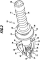
- a pipe cleaning nozzle 10 according to the invention is schematically shown, which has at its front end a nozzle head 12, to which a connecting part 14 connects at the rear.
- the nozzle head 12 and the connecting part 14 are integrally connected to each other, they are in the form of a one-piece plastic molded part.
- the nozzle head 12 has an aligned to the connecting part 14 aligned central part 16, from the three wing-like ribs 18, 19, 20 in the circumferential direction at a uniform distance from each other protrude radially outward.
- the provision of three ribs, as used in the preferred embodiment is, however, not mandatory, alternatively, only two ribs could be provided or even more than three ribs.
- the ribs 18, 19 and 20 form a common tip 22 of the nozzle head 12, from which the ribs 18, 19 and 20 extend with an arcuate outer edge 24 to the rear in the direction of the connecting part 14. Facing the connection part 14, the three ribs 18, 19 and 20 each have a nozzle outlet surface 26, 27 and 28, respectively.
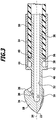
- the Düsenauslass vom 26, 27 and 28 are aligned obliquely to a radial plane, wherein they are the connection part 14 facing away, ie they are inclined in the direction of the tip 22. This is especially true FIG. 3 clear.
- the three ribs 18, 19 and 20 are respectively penetrated by an outlet channel 30, which opens into the respective nozzle outlet surface 26, 27 and 28 and which emanates from a central supply channel 32.
- the supply channel 32 extends in the longitudinal direction through the complete connection part 14 and ends in the manner of a blind bore in the region of the central part 16. From the supply channel 32 branches off obliquely to the rear, ie at an acute angle to the longitudinal axis 34 of the pipe cleaning nozzle 10 aligned outlet channels 30 from. Again, this will be particular FIG. 3 clear.
- the connecting part 14 has a connecting piece 36, which carries on its outer periphery in the manner of barbs formed projections.
- a first annular collar 38 connects, which has a first stop surface 40.
- the first stop surface 40 faces away from the nozzle head 12 and in a radial plane aligned, ie in a direction perpendicular to the longitudinal axis 34 aligned plane.
- a second annular collar 32 is arranged at a distance from the first annular collar 38, which has a second stop surface 44 and extends in the radial direction beyond the first annular collar 38 addition.
- the second annular collar 42 is arranged at a distance from the nozzle head 12, between the second annular collar 42 and the nozzle head 12, the connecting part 14 forms a aligned to the connecting piece 36 connecting line 46 which is designed as a hollow cylinder and as well as the connecting piece 36 is penetrated by the supply channel 32.
- the pipe cleaning nozzle 10 may be fixed to a hose 50.
- the connecting piece 36 can in this case be inserted into the tube 50, and then the end piece of the tube 50 receiving the connecting piece 36 can be pressed by means of a compression sleeve 54 with the connecting piece 36.
- the connecting piece 36 can be inserted so far into the tube 50 until the end face 56 of the tube 50 comes to rest on the first stop surface 40.
- the previously pushed over the tube 50 pressing sleeve 54 can then be moved so far in the direction of the nozzle head 12 until it abuts against the second stop surface 44.
- the compression sleeve 54 can be pressed with the connecting piece 36 receiving end piece 52 of the hose 50. This is especially true FIG. 3 clear.
- the pipe cleaning nozzle 10 To clean a clogged pipe, the pipe cleaning nozzle 10, after being fixed to the hose 50, can be inserted into the pipe to be cleaned. Subsequently, then the pipe cleaning nozzle 10 via the hose 50 under pressure cleaning liquid, preferably pressurized water, are supplied.
- the cleaning liquid can flow through the feed channel 32 and then be discharged obliquely outwards via the outlet channels 30.
- the pressurized liquid is formed into a stream by the outlet channels 30, respectively. which is oriented at an acute angle to the longitudinal axis 34 and in the direction away from the tip 22 is discharged obliquely backwards. By means of the liquid jets the pipe can be cleaned.
- the outlet channels 30 can have a considerable length and at the same time the material thickness of the nozzle head 12 in the region between the ribs 18, 19 and 20 can be kept relatively low. This makes it possible to reduce the weight of the pipe cleaning nozzle 10 while at the same time increasing its stability while providing it with considerable propulsion from the pressurized liquid.
Landscapes
- Engineering & Computer Science (AREA)
- Mechanical Engineering (AREA)
- Nozzles (AREA)
- Cleaning In General (AREA)
Description
- Die Erfindung betrifft eine Rohrreinigungsdüse mit den Merkmalen des Oberbegriffes von Patentanspruch 1.
Eine derartige Rohrreinigungsdüse kann an einen Schlauch angeschlossen werden, über den der Rohrreinigungsdüse eine unter Druck stehende Reinigungsflüssigkeit, insbesondere Wasser, zugeführt werden kann. Die am Schlauch festgelegte Rohrreinigungsdüse kann beispielsweise in ein verstopftes Rohr eingeführt werden um dieses zu reinigen. Der Düsenkopf weist mehrere Auslasskanäle für die unter Druck stehende Reinigungsflüssigkeit auf.
Dies Auslasskanäle sind schräg nach hinten ausgerichtet, d. h. sie sind in einem spitzen Winkel zur Längsachse des Anschlussteiles ausgerichtet, so dass die über die Auslasskanäle aus dem Düsenkopf austretenden Flüssigkeitsstrahlen eine radiale und eine rückwärts gerichtete axiale Strömungskomponente aufweisen. Die axial nach hinten gerichtete Komponente bewirkt einen Vortrieb der Rohrreinigungsdüse, so dass sich diese zusammen mit dem angeschlossenen Schlauch durch das zu reinigende Rohr hindurchbewegt. - Aus der
DE 299 03 540 U1 ist eine Rohrreinigungsdüse bekannt, bei der der Düsenkopf in Form einer Halbkugel ausgestaltet ist, die mit einem Anschlussteil verschweißt ist. Das Anschlussteil kann mit einem Schlauchnippel verschraubt werden, der am Schlauch festgelegt werden kann.
In derUS-A-3,080,265 ist eine Rohrreinigungsdüse beschrieben, bei der der Schlauch unmittelbar auf das einstückig mit dem Düsenkopf verbundene Anschlussteil aufgesteckt werden kann. - Aus dem Dokument
EP 0 936 319 ist eine Rohrreinigungsdüse bekannt, deren Düsenkopf einen Druckwasseranschluss mit einem Innengewinde aufweist. In den Druckwasseranschluss kann ein Anschlussteil eingeschraubt werden. An den Druckwasseranschluss schließen sich in einem hinteren Endbereich des Düsenkopfs mehrere Druckwasserkanäle an, die bogenförmig gekrümmt sind und in eine rückwärtige Endfläche des Düsenkopfes münden. Im Abstand zu den Druckwasserkanälen bildet der Düsenkopf in einem vorderen Endbereich vier flügelartige Rippen, die in Umfangsrichtung des Düsenkopfs gleichmäßig verteilt angeordnet sind. Der Düsenkopf ist als kompakter Gusskörper ausgestaltet, der aus einer hochverschleißfesten Gusslegierung, aus einem Sintermetall oder aus einem Keramikmaterial gefertigt ist. - Das Dokument
US 3,814,330 A offenbart eine Rohrreinigungsdüse gemäß dem Oberbegriff des Patentanspruchs 1, mit einem Düsenkopf, der mehrere, in gleichmäßigem Abstand zueinander angeordnete Rippen aufweist, durch die sich jeweils zwei nach hinten gerichtete Auslasskanäle hindurch erstrecken. An einer rückwärtigen Endfläche weist der Düsenkopf einen Druckwasseranschluss auf, in den ein Anschlussteil für einen Schlauch eingeschraubt werden kann.
Aufgabe der vorliegenden Erfindung ist es, eine Rohrreinigungsdüse der gattungsgemäßen Art derart weiterzubilden, dass sie kostengünstiger herstellbar ist, eine einfache Montage an einem Schlauch ermöglicht und eine hohe mechanische Belastbarkeit aufweist.
Diese Aufgabe wird durch eine Rohrreinigungsdüse mit den Merkmalen von Patentanspruch 1 gelöst.
Die erfindungsgemäße Rohrreinigungsdüse weist mehrere flügelartige Rippen auf, die von einem Zentralteil des Düsenkopfs vorzugsweise radial abstehen. Durch die Rippen erstreckt sich jeweils ein Auslasskanal, über den die über den Schlauch zugeführte, unter Druck stehende Reinigungsflüssigkeit abgegeben werden kann. Die Ausgestaltung des Düsenkopfes mit flügelartigen Rippen führt zu einer verbesserten Vorwärtsbewegung der Rohrreinigungsdüse mit dem daran festgelegten Schlauch, wenn über die Auslasskanäle unter Druck stehende Reinigungsflüssigkeit abgegeben wird. Die flügelartigen Rippen führen auch zu einer Stabilisierung der Rohrreinigungsdüse bei der Abgabe von unter Druck stehender Reinigungsflüssigkeit. Darüber hinaus kann im Bereich zwischen benachbarten Rippen die Materialstärke des Düsenkopfes reduziert werden. Dies führt zu einer Gewichtsverminderung des Düsenkopfes, so dass der über den Rückstoß der austretenden Flüssigkeit bereitgestellte Vortrieb zu einer erhöhten Beschleunigung des Düsenkopfes in Vorwärtsrichtung führt. Die verminderte Materialstärke des Düsenkopfes im Bereich zwischen benachbarten Rippen hat darüber hinaus den Vorteil, dass der Düsenkopf auf einfache und kostengünstige Weise aus einem Kunststoffmaterial geformt werden kann. - Die jeweils in einer flügelartigen Rippe verlaufenden Auslasskanäle können eine verhältnismäßig große Länge aufweisen, so dass die über die Auslasskanäle aus dem Düsenkopf austretende, unter Druck stehende Reinigungsflüssigkeit einen Strahl ausbilden kann, insbesondere einen Punktstrahl. Dadurch wird das Ablösen von Verschmutzungen in dem zu reinigenden Rohr erleichtert.
- Erfindungsgemäß sind der Düsenkopf und das Anschlussteil einteilig miteinander verbunden, wobei sie als einteiliges Kunststoffformteil ausgestaltet sind und wobei das Anschlussteil einen Anschlussstutzen umfasst, der in den Schlauch einführbar ist. Ein separater Schlauchnippel, der einerseits mit dem Schlauch und andererseits mit der Rohrreinigungsdüse zu verbinden ist, kann dadurch entfallen. Die Montage der Rohrreinigungsdüse am Schlauch wird dadurch vereinfacht.
- Das Anschlussteil umfasst eine erste Anschlagfläche für die Stirnseite des Schlauches. Die erste Anschlagfläche begrenzt die Länge des Anschlussstutzens. Der Anschlussstutzen kann somit so weit in den Schlauch eingeführt werden, bis die Stirnseite des Schlauches an der ersten Anschlagfläche zur Anlage gelangt.
- Die erste Anschlagfläche ist an einem ersten Ringbund des Anschlussteiles angeordnet, der sich in Richtung auf den Düsenkopf an den Anschlussstutzen anschließt. Der Ringbund kann sich in Umfangsrichtung des Anschlussteiles über 360° erstrecken.
- Günstigerweise ist die erste Anschlagfläche in einer Radialebene bezogen auf die Längsachse der Rohrreinigungsdüse ausgerichtet.
- Günstig ist es, wenn der Düsenkopf drei Rippen aufweist, durch die sich jeweils eine Auslasskammer hindurch erstreckt. Die Bereitstellung von drei Rippen, die jeweils in einem Winkelabstand von 120° zueinander angeordnet sind, führt zu einer stabileren Ausrichtung der Rohrreinigungsdüse bei der Abgabe von unter Druck stehender Reinigungsflüssigkeit, Die Gefahr, dass die Rohrreinigungsdüse um ihre Längsachse verdreht wird und dadurch der an der Rohrreinigungsdüse festgelegte Schlauch einer Torsionsbelastung unterliegt, kann dadurch gering gehalten werden.
- Bevorzugt weist der Düsenkopf eine Spitze auf, von der aus die flügelartigen Rippen schräg nach hinten verlaufen. Bei einer derartigen Ausgestaltung weist die Rohrreinigungsdüse im Wesentlichen die Form einer Harpune auf. Dies erleichtert das Hindurchführen der Rohrreinigungsdüse mit dem daran festgelegten Schlauch durch ein verstopftes Rohr hindurch.
- Besonders günstig ist es, wenn die Rippen eine bogenförmige Außenkante aufweisen. Der Strömungswiderstand der Rohrreinigungsdüse kann dadurch gering gehalten werden.
- Bei einer vorteilhaften Ausführungsform der Erfindung weisen die Rippen eine schräg nach hinten gerichtete Düsenauslassfläche aus, in die jeweils ein Auslasskanal einmündet. Die Düsenauslassflächen sind somit nicht radial ausgerichtet sondern verlaufen schräg zur Radialrichtung. Dies erleichtert die Herstellung der Auslasskanäle.
- Von Vorteil ist es, wenn das Anschlussteil eine zweite Anschlagfläche aufweist für eine Presshülse zum Verpressen des Schlauches mit dem Anschlussstutzen. Die Festlegung der Rohrreinigungsdüse am Schlauch kann dergestalt erfolgen, dass der Anschlussstutzen in den Schlauch eingeführt und anschließend der Schlauch mittels einer den Schlauch umgebenden Presshülse mit dem Anschlussstutzen verpresst wird. Durch die Bereitstellung der zweiten Anschlagfläche, an der die Presshülse stirnseitig zur Anlage gelangen kann, wird die Positionierung der Presshülse auf dem den Anschlussstutzen umgebenden Endstück des Schlauches erleichtert.
- Die zweite Anschlagfläche ist günstigerweise an einem zweiten Ringbund angeordnet, der zwischen dem Anschlussstutzen und dem Düsenkopf positioniert ist.
- Insbesondere kann vorgesehen sein, dass der zweite Ringbund einen Abstand zum ersten Ringbund einnimmt.
- Von besonderem Vorteil ist es, wenn der zweite Ringbund im Abstand zum Düsenkopf angeordnet ist. Bei einer derartigen Ausgestaltung weist die Rohrreinigungsdüse zwischen dem zweiten Ringbund und dem Düsenkopf einen Leitungsabschnitt auf, der beispielsweise zylinderförmig ausgebildet sein kann.
- Die nachfolgende Beschreibung einer besonders bevorzugten Ausführungsform der Erfindung dient im Zusammenhang mit der Zeichnung der näheren Erläuterung. Es zeigen:
- Figur 1:
- eine perspektivische Darstellung einer erfindungsgemäßen Rohrreinigungsdüse schräg von vorne;
- Figur 2:
- eine perspektivische Darstellung der Rohrreinigungsdüse aus
Figur 1 schräg von hinten und - Figur 3:
- eine Längsschnittansicht der Rohrreinigungsdüse aus
Figur 1 , wobei an die Rohrreinigungsdüse ein Schlauch angeschlossen ist. - In der Zeichnung ist schematisch eine erfindungsgemäße Rohrreinigungsdüse 10 dargestellt, die an ihrem vorderen Ende einen Düsenkopf 12 aufweist, an den sich rückseitig ein Anschlussteil 14 anschließt. Der Düsenkopf 12 und das Anschlussteil 14 sind einstückig miteinander verbunden, sie sind in Form eines einteiligen Kunststoffformteiles ausgebildet.
- Der Düsenkopf 12 weist ein fluchtend zum Anschlussteil 14 ausgerichtetes Zentralteil 16 auf, von dem drei flügelartige Rippen 18, 19, 20 in Umfangsrichtung in gleichmäßigem Abstand zueinander radial nach außen abstehen. Die Bereitstellung von drei Rippen, wie sie in der bevorzugten Ausführungsform zum Einsatz kommen, ist jedoch nicht zwingend erforderlich, alternativ könnten auch nur zwei Rippen vorgesehen sein oder auch mehr als drei Rippen.
- Die Rippen 18, 19 und 20 bilden eine gemeinsame Spitze 22 des Düsenkopfes 12, von der aus die Rippen 18, 19 und 20 mit einer bogenförmigen Außenkante 24 nach hinten in Richtung des Anschlussteiles 14 verlaufen. Dem Anschlussteil 14 zugewandt weisen die drei Rippen 18, 19 und 20 jeweils eine Düsenauslassfläche 26, 27 bzw. 28 auf. Die Düsenauslassflächen 26, 27 und 28 sind schräg zu einer Radialebene ausgerichtet, wobei sie dem Anschlussteil 14 abgewandt sind, d. h. sie sind in Richtung der Spitze 22 geneigt. Dies wird insbesondere aus
Figur 3 deutlich. - Die drei Rippen 18, 19 und 20 werden jeweils von einem Auslasskanal 30 durchgriffen, der in die jeweilige Düsenauslassfläche 26, 27 bzw. 28 einmündet und der von einem zentralen Zuführungskanal 32 ausgeht. Der Zuführungskanal 32 erstreckt sich in Längsrichtung durch das komplette Anschlussteil 14 hindurch und endet nach Art einer Sackbohrung im Bereich des Zentralteiles 16. Vom Zuführungskanal 32 zweigen die schräg nach hinten, also in einem spitzen Winkel zur Längsachse 34 der Rohrreinigungsdüse 10 ausgerichteten Auslasskanäle 30 ab. Auch dies wird insbesondere aus
Figur 3 deutlich. - Das Anschlussteil 14 weist einen Anschlussstutzen 36 auf, der an seinem Außenumfang nach Art von Widerhaken ausgebildete Vorsprünge trägt. An den Anschlussstutzen 36 schließt sich in Richtung auf den Düsenkopf 12 ein erster Ringbund 38 an, der eine erste Anschlagfläche 40 aufweist. Die erste Anschlagfläche 40 ist dem Düsenkopf 12 abgewandt und in einer Radialebene ausgerichtet, d. h. in einer senkrecht zur Längsachse 34 ausgerichteten Ebene.
- In Richtung auf den Düsenkopf 12 ist im Abstand zum ersten Ringbund 38 ein zweiter Ringbund 32 angeordnet, der eine zweite Anschlagfläche 44 aufweist und sich in Radialrichtung über den ersten Ringbund 38 hinaus erstreckt. Der zweite Ringbund 42 ist im Abstand zum Düsenkopf 12 angeordnet, zwischen dem zweiten Ringbund 42 und dem Düsenkopf 12 bildet das Anschlussteil 14 eine fluchtend zum Anschlussstutzen 36 ausgerichtete Verbindungsleitung 46, die hohlzylindrisch ausgestaltet ist und ebenso wie der Anschlussstutzen 36 vom Zuführungskanal 32 durchgriffen ist.
- Die Rohrreinigungsdüse 10 kann an einem Schlauch 50 festgelegt werden. Der Anschlussstutzen 36 kann hierbei in den Schlauch 50 eingeführt werden, und anschließend kann das den Anschlussstutzen 36 aufnehmende Endstück des Schlauches 50 mittels einer Presshülse 54 mit dem Anschlussstutzen 36 verpresst werden. Der Anschlussstutzen 36 kann so weit in den Schlauch 50 eingeführt werden, bis die Stirnseite 56 des Schlauches 50 an der ersten Anschlagfläche 40 zur Anlage gelangt. Die zuvor über den Schlauch 50 geschobene Presshülse 54 kann dann so weit in Richtung auf den Düsenkopf 12 verschoben werden, bis sie an der zweiten Anschlagfläche 44 anschlägt. Anschließend kann dann die Presshülse 54 mit dem den Anschlussstutzen 36 aufnehmenden Endstück 52 des Schlauches 50 verpresst werden. Dies wird insbesondere aus
Figur 3 deutlich. - Zur Reinigung eines verstopften Rohres kann die Rohrreinigungsdüse 10, nachdem sie am Schlauch 50 festgelegt wurde, in das zu reinigende Rohr eingeführt werden. Anschließend kann dann der Rohrreinigungsdüse 10 über den Schlauch 50 unter Druck stehende Reinigungsflüssigkeit, vorzugsweise unter Druck stehendes Wasser, zugeführt werden. Die Reinigungsflüssigkeit kann den Zuführungskanal 32 durchströmen und anschließend über die Auslasskanäle 30 schräg nach außen abgegeben werden. Die unter Druck stehende Flüssigkeit wird von den Auslasskanälen 30 jeweils zu einem Strahl geformt, der in einem spitzen Winkel zur Längsachse 34 ausgerichtet ist und in die der Spitze 22 abgewandte Richtung schräg nach hinten abgegeben wird. Mittels der Flüssigkeitsstrahlen kann das Rohr gereinigt werden.
- Durch die Bereitstellung der flügelartig vom Zentralteil 16 nach außen abstehenden Rippen 18, 19 und 20 können die Auslasskanäle 30 eine beachtliche Länge aufweisen und gleichzeitig kann die Materialstärke des Düsenkopfes 12 im Bereich zwischen den Rippen 18, 19 und 20 verhältnismäßig gering gehalten werden. Dies ermöglicht es, das Gewicht der Rohrreinigungsdüse 10 zu verringern und gleichzeitig deren Stabilität zu erhöhen, wobei ihr von der unter Druck stehenden Flüssigkeit ein beachtlicher Vortrieb bereitgestellt wird.
Claims (8)
- Rohrreinigungsdüse mit einem Düsenkopf (12) zum Abgeben einer unter Druck stehenden Reinigungsflüssigkeit und mit einem Anschlussteil (14) zum Anschließen eines Schlauches, wobei der Düsenkopf (12) ein Zentralteil (16) aufweist, von dem mehrere in Umfangsrichtung des Zentralteils (16) in gleichmäßigem Abstand zueinander angeordnete flügelartige Rippen (18, 19, 20) nach außen abstehen, durch die sich jeweils ein schräg nach hinten ausgerichteter Auslasskanal (30) hindurch erstreckt, dadurch gekennzeichnet, dass der Düsenkopf (12) und das Anschlussteil (14) einteilig miteinander verbunden sind, wobei sie als einteiliges Kunststoffformteil ausgestaltet sind, und wobei das Anschlussteil (14) einen Anschlussstutzen (36) aufweist, der in den Schlauch (50) einführbar ist, wobei das Anschlussteil (14) eine erste Anschlagfläche (40) für die Stirnseite des Schlauches (50) aufweist und die erste Anschlagfläche (40) an einem ersten Ringbund (38) angeordnet ist, der sich in Richtung auf den Düsenkopf (12) an den Anschlussstutzen (36) anschließt.
- Rohrreinigungsdüse nach Anspruch 1, dadurch gekennzeichnet, dass der Düsenkopf (12) drei Rippen (18, 19, 20) aufweist, durch die sich jeweils ein Auslasskanal (30) hindurch erstreckt.
- Rohrreinigungsdüse nach Anspruch 1 oder 2, dadurch gekennzeichnet, dass der Düsenkopf (12) eine Spitze (22) aufweist, von der aus die Rippen (18, 19, 20) schräg nach hinten verlaufen.
- Rohrreinigungsdüse nach einem der voranstehenden Ansprüche, dadurch gekennzeichnet, dass die Rippen (18, 19, 20) eine bogenförmige Außenkante (24) aufweisen.
- Rohrreinigungsdüse nach einem der voranstehenden Ansprüche, dadurch gekennzeichnet, dass die Rippen (18, 19, 20) eine schräg nach hinten gerichtete Düsenauslassfläche (26, 27, 28) aufweisen, in die jeweils ein Auslasskanal (30) einmündet.
- Rohrreinigungsdüse nach einem der voranstehenden Ansprüche, dadurch gekennzeichnet, dass das Anschlussteil (14) eine zweite Anschlagfläche (44) aufweist für eine Presshülse (54) zum Verpressen des Schlauches (50) mit dem Anschlussstutzen (36).
- Rohrreinigungsdüse nach Anspruch 6, dadurch gekennzeichnet, dass die zweite Anschlagfläche (44) an einem zweiten Ringbund (42) angeordnet ist, der zwischen dem Anschlussstutzen (36) und dem Düsenkopf (12) positioniert ist.
- Rohrreinigungsdüse nach Anspruch 7, dadurch gekennzeichnet, dass der zweite Ringbund (42) im Abstand zum Düsenkopf (12) angeordnet ist.
Applications Claiming Priority (2)
| Application Number | Priority Date | Filing Date | Title |
|---|---|---|---|
| DE102010038565A DE102010038565A1 (de) | 2010-07-28 | 2010-07-28 | Rohrreinigungsdüse |
| PCT/EP2011/061050 WO2012013441A2 (de) | 2010-07-28 | 2011-06-30 | Rohrreinigungsdüse |
Publications (2)
| Publication Number | Publication Date |
|---|---|
| EP2598258A2 EP2598258A2 (de) | 2013-06-05 |
| EP2598258B1 true EP2598258B1 (de) | 2019-03-06 |
Family
ID=44627851
Family Applications (1)
| Application Number | Title | Priority Date | Filing Date |
|---|---|---|---|
| EP11729301.9A Active EP2598258B1 (de) | 2010-07-28 | 2011-06-30 | Rohrreinigungsdüse |
Country Status (4)
| Country | Link |
|---|---|
| EP (1) | EP2598258B1 (de) |
| CN (1) | CN103037990B (de) |
| DE (1) | DE102010038565A1 (de) |
| WO (1) | WO2012013441A2 (de) |
Families Citing this family (2)
| Publication number | Priority date | Publication date | Assignee | Title |
|---|---|---|---|---|
| US12459014B2 (en) | 2019-10-09 | 2025-11-04 | Aquateq Sweden Ab | Nozzle for cleaning the interior of a pipe, a system including such a nozzle and a method for cleaning the interior of a pipe |
| CN116651836B (zh) * | 2023-05-31 | 2025-10-28 | 中国南玻集团股份有限公司 | 下进酸式酸洗罐 |
Family Cites Families (6)
| Publication number | Priority date | Publication date | Assignee | Title |
|---|---|---|---|---|
| GB355316A (en) * | 1930-05-09 | 1931-08-10 | Sidney Charles Sladden | Improvements in nozzles |
| US3080265A (en) | 1959-10-28 | 1963-03-05 | Oskar Maasberg Fa | Process and apparatus for cleaning waste-disposal systems |
| US3814330A (en) * | 1973-03-01 | 1974-06-04 | Mcneil Corp | Nozzle |
| JPH11100891A (ja) * | 1997-09-29 | 1999-04-13 | Hiroshi Morita | 管内異物除去用ノズル |
| DE19805374C2 (de) * | 1998-02-11 | 2000-03-23 | Richard Siedler | Reinigungskörper für Rohrleitungen und Kanalisationssysteme |
| CN201375979Y (zh) * | 2009-01-24 | 2010-01-06 | 番禺珠江钢管有限公司 | 清洗钢管内壁的喷水头 |
-
2010
- 2010-07-28 DE DE102010038565A patent/DE102010038565A1/de not_active Withdrawn
-
2011
- 2011-06-30 WO PCT/EP2011/061050 patent/WO2012013441A2/de not_active Ceased
- 2011-06-30 CN CN201180037018.3A patent/CN103037990B/zh active Active
- 2011-06-30 EP EP11729301.9A patent/EP2598258B1/de active Active
Non-Patent Citations (1)
| Title |
|---|
| None * |
Also Published As
| Publication number | Publication date |
|---|---|
| CN103037990A (zh) | 2013-04-10 |
| EP2598258A2 (de) | 2013-06-05 |
| WO2012013441A2 (de) | 2012-02-02 |
| CN103037990B (zh) | 2015-09-02 |
| DE102010038565A1 (de) | 2012-02-02 |
| WO2012013441A3 (de) | 2013-01-31 |
Similar Documents
| Publication | Publication Date | Title |
|---|---|---|
| DE102015105047A1 (de) | Reduziermuffe mit Kühlmitteldurchfluss und eine Schneidevorrichtung, die eine solche Reduziermuffe verwendet | |
| EP2775187B1 (de) | Vorrichtung für eine schlaucharmatur | |
| DE202012101623U1 (de) | Spritzdüsenbaugruppe für pressluftbetriebene Reinigungsgeräte | |
| DE102015204664A1 (de) | Flachstrahldüse und Verwendung einer Flachstrahldüse | |
| DE69830527T2 (de) | Hochdruckreinigungsdüse | |
| DE102014200582A1 (de) | Werkzeugaufnahme mit einem Düsenring | |
| DE102015119813A1 (de) | Reinigungskolben mit unpolarem Werkstoff sowie Mischkopf mit Reinigungskolben und Auslaufkanal | |
| EP0742053A1 (de) | Hydrodynamische Düse für die Reinigung von Rohren und Kanälen | |
| DE4002742C2 (de) | Wasserbedüsung für Schräm- oder Schneidkörper im Bergbau | |
| WO2015132235A1 (de) | Verlängerungsvorrichtung für spritzapparate und spritzapparat | |
| EP3326727A2 (de) | Vorrichtung zur inspektion und reinigung eines leitungs- oder rohrabschnitts | |
| DE102011053012A1 (de) | Schneidring-Vormontagegerät für Rohrverschraubungen | |
| DE69919250T2 (de) | Schnellkupplungssystem | |
| EP2598258A2 (de) | Rohrreinigungsdüse | |
| EP2393603B1 (de) | Lanze | |
| EP2238313B1 (de) | Ankerrohr und verfahren zu dessen herstellung | |
| WO2009092632A1 (de) | Injektionsstutzen | |
| DE4312994C2 (de) | Vorrichtung zur Verspritzung von Suspensionen, insbesondere Mörteln | |
| DE10161144A1 (de) | Zugfeste Rohrverbindung | |
| DE102019107292A1 (de) | Hochdruckwerkzeug und Verfahren zum Herstellen eines Hochdruckwerkzeugs | |
| DE202017005877U1 (de) | Düse zum Einbau in eine Reinigungsdüse | |
| EP3561358B1 (de) | Verstärkungshülse, schneidringverschraubung und verfahren | |
| DE202017104354U1 (de) | Vorrichtung zur hydrodynamischen Beseitigung von Störstellen im Inneren von Rohrleitungen, insbesondere zur Sanierung und Reinigung von wasserführenden Rohrleitungen im häuslichen, kommunalen und industriellen Bereich | |
| WO2010139303A1 (de) | Düsenhalterung | |
| DE10153224B4 (de) | Verfahren und Vorrichtung zum Formen und/oder Beschneiden eines Hohlkörpers aus einem Hohlprofil od.dgl. Werkstück |
Legal Events
| Date | Code | Title | Description |
|---|---|---|---|
| PUAI | Public reference made under article 153(3) epc to a published international application that has entered the european phase |
Free format text: ORIGINAL CODE: 0009012 |
|
| 17P | Request for examination filed |
Effective date: 20130125 |
|
| AK | Designated contracting states |
Kind code of ref document: A2 Designated state(s): AL AT BE BG CH CY CZ DE DK EE ES FI FR GB GR HR HU IE IS IT LI LT LU LV MC MK MT NL NO PL PT RO RS SE SI SK SM TR |
|
| DAX | Request for extension of the european patent (deleted) | ||
| STAA | Information on the status of an ep patent application or granted ep patent |
Free format text: STATUS: EXAMINATION IS IN PROGRESS |
|
| 17Q | First examination report despatched |
Effective date: 20180103 |
|
| RAP1 | Party data changed (applicant data changed or rights of an application transferred) |
Owner name: ALFRED KAERCHER SE & CO. KG |
|
| GRAP | Despatch of communication of intention to grant a patent |
Free format text: ORIGINAL CODE: EPIDOSNIGR1 |
|
| STAA | Information on the status of an ep patent application or granted ep patent |
Free format text: STATUS: GRANT OF PATENT IS INTENDED |
|
| INTG | Intention to grant announced |
Effective date: 20181011 |
|
| GRAS | Grant fee paid |
Free format text: ORIGINAL CODE: EPIDOSNIGR3 |
|
| GRAA | (expected) grant |
Free format text: ORIGINAL CODE: 0009210 |
|
| STAA | Information on the status of an ep patent application or granted ep patent |
Free format text: STATUS: THE PATENT HAS BEEN GRANTED |
|
| AK | Designated contracting states |
Kind code of ref document: B1 Designated state(s): AL AT BE BG CH CY CZ DE DK EE ES FI FR GB GR HR HU IE IS IT LI LT LU LV MC MK MT NL NO PL PT RO RS SE SI SK SM TR |
|
| REG | Reference to a national code |
Ref country code: GB Ref legal event code: FG4D Free format text: NOT ENGLISH |
|
| REG | Reference to a national code |
Ref country code: CH Ref legal event code: EP Ref country code: AT Ref legal event code: REF Ref document number: 1103846 Country of ref document: AT Kind code of ref document: T Effective date: 20190315 |
|
| REG | Reference to a national code |
Ref country code: DE Ref legal event code: R096 Ref document number: 502011015453 Country of ref document: DE |
|
| REG | Reference to a national code |
Ref country code: IE Ref legal event code: FG4D Free format text: LANGUAGE OF EP DOCUMENT: GERMAN |
|
| REG | Reference to a national code |
Ref country code: NL Ref legal event code: MP Effective date: 20190306 |
|
| REG | Reference to a national code |
Ref country code: LT Ref legal event code: MG4D |
|
| PG25 | Lapsed in a contracting state [announced via postgrant information from national office to epo] |
Ref country code: LT Free format text: LAPSE BECAUSE OF FAILURE TO SUBMIT A TRANSLATION OF THE DESCRIPTION OR TO PAY THE FEE WITHIN THE PRESCRIBED TIME-LIMIT Effective date: 20190306 Ref country code: NO Free format text: LAPSE BECAUSE OF FAILURE TO SUBMIT A TRANSLATION OF THE DESCRIPTION OR TO PAY THE FEE WITHIN THE PRESCRIBED TIME-LIMIT Effective date: 20190606 Ref country code: SE Free format text: LAPSE BECAUSE OF FAILURE TO SUBMIT A TRANSLATION OF THE DESCRIPTION OR TO PAY THE FEE WITHIN THE PRESCRIBED TIME-LIMIT Effective date: 20190306 Ref country code: FI Free format text: LAPSE BECAUSE OF FAILURE TO SUBMIT A TRANSLATION OF THE DESCRIPTION OR TO PAY THE FEE WITHIN THE PRESCRIBED TIME-LIMIT Effective date: 20190306 |
|
| PG25 | Lapsed in a contracting state [announced via postgrant information from national office to epo] |
Ref country code: GR Free format text: LAPSE BECAUSE OF FAILURE TO SUBMIT A TRANSLATION OF THE DESCRIPTION OR TO PAY THE FEE WITHIN THE PRESCRIBED TIME-LIMIT Effective date: 20190607 Ref country code: NL Free format text: LAPSE BECAUSE OF FAILURE TO SUBMIT A TRANSLATION OF THE DESCRIPTION OR TO PAY THE FEE WITHIN THE PRESCRIBED TIME-LIMIT Effective date: 20190306 Ref country code: RS Free format text: LAPSE BECAUSE OF FAILURE TO SUBMIT A TRANSLATION OF THE DESCRIPTION OR TO PAY THE FEE WITHIN THE PRESCRIBED TIME-LIMIT Effective date: 20190306 Ref country code: BG Free format text: LAPSE BECAUSE OF FAILURE TO SUBMIT A TRANSLATION OF THE DESCRIPTION OR TO PAY THE FEE WITHIN THE PRESCRIBED TIME-LIMIT Effective date: 20190606 Ref country code: LV Free format text: LAPSE BECAUSE OF FAILURE TO SUBMIT A TRANSLATION OF THE DESCRIPTION OR TO PAY THE FEE WITHIN THE PRESCRIBED TIME-LIMIT Effective date: 20190306 Ref country code: HR Free format text: LAPSE BECAUSE OF FAILURE TO SUBMIT A TRANSLATION OF THE DESCRIPTION OR TO PAY THE FEE WITHIN THE PRESCRIBED TIME-LIMIT Effective date: 20190306 |
|
| PG25 | Lapsed in a contracting state [announced via postgrant information from national office to epo] |
Ref country code: EE Free format text: LAPSE BECAUSE OF FAILURE TO SUBMIT A TRANSLATION OF THE DESCRIPTION OR TO PAY THE FEE WITHIN THE PRESCRIBED TIME-LIMIT Effective date: 20190306 Ref country code: IT Free format text: LAPSE BECAUSE OF FAILURE TO SUBMIT A TRANSLATION OF THE DESCRIPTION OR TO PAY THE FEE WITHIN THE PRESCRIBED TIME-LIMIT Effective date: 20190306 Ref country code: AL Free format text: LAPSE BECAUSE OF FAILURE TO SUBMIT A TRANSLATION OF THE DESCRIPTION OR TO PAY THE FEE WITHIN THE PRESCRIBED TIME-LIMIT Effective date: 20190306 Ref country code: SK Free format text: LAPSE BECAUSE OF FAILURE TO SUBMIT A TRANSLATION OF THE DESCRIPTION OR TO PAY THE FEE WITHIN THE PRESCRIBED TIME-LIMIT Effective date: 20190306 Ref country code: PT Free format text: LAPSE BECAUSE OF FAILURE TO SUBMIT A TRANSLATION OF THE DESCRIPTION OR TO PAY THE FEE WITHIN THE PRESCRIBED TIME-LIMIT Effective date: 20190706 Ref country code: ES Free format text: LAPSE BECAUSE OF FAILURE TO SUBMIT A TRANSLATION OF THE DESCRIPTION OR TO PAY THE FEE WITHIN THE PRESCRIBED TIME-LIMIT Effective date: 20190306 Ref country code: CZ Free format text: LAPSE BECAUSE OF FAILURE TO SUBMIT A TRANSLATION OF THE DESCRIPTION OR TO PAY THE FEE WITHIN THE PRESCRIBED TIME-LIMIT Effective date: 20190306 Ref country code: RO Free format text: LAPSE BECAUSE OF FAILURE TO SUBMIT A TRANSLATION OF THE DESCRIPTION OR TO PAY THE FEE WITHIN THE PRESCRIBED TIME-LIMIT Effective date: 20190306 |
|
| PG25 | Lapsed in a contracting state [announced via postgrant information from national office to epo] |
Ref country code: SM Free format text: LAPSE BECAUSE OF FAILURE TO SUBMIT A TRANSLATION OF THE DESCRIPTION OR TO PAY THE FEE WITHIN THE PRESCRIBED TIME-LIMIT Effective date: 20190306 Ref country code: PL Free format text: LAPSE BECAUSE OF FAILURE TO SUBMIT A TRANSLATION OF THE DESCRIPTION OR TO PAY THE FEE WITHIN THE PRESCRIBED TIME-LIMIT Effective date: 20190306 |
|
| REG | Reference to a national code |
Ref country code: DE Ref legal event code: R097 Ref document number: 502011015453 Country of ref document: DE |
|
| PG25 | Lapsed in a contracting state [announced via postgrant information from national office to epo] |
Ref country code: IS Free format text: LAPSE BECAUSE OF FAILURE TO SUBMIT A TRANSLATION OF THE DESCRIPTION OR TO PAY THE FEE WITHIN THE PRESCRIBED TIME-LIMIT Effective date: 20190706 |
|
| PLBE | No opposition filed within time limit |
Free format text: ORIGINAL CODE: 0009261 |
|
| STAA | Information on the status of an ep patent application or granted ep patent |
Free format text: STATUS: NO OPPOSITION FILED WITHIN TIME LIMIT |
|
| PG25 | Lapsed in a contracting state [announced via postgrant information from national office to epo] |
Ref country code: DK Free format text: LAPSE BECAUSE OF FAILURE TO SUBMIT A TRANSLATION OF THE DESCRIPTION OR TO PAY THE FEE WITHIN THE PRESCRIBED TIME-LIMIT Effective date: 20190306 Ref country code: MC Free format text: LAPSE BECAUSE OF FAILURE TO SUBMIT A TRANSLATION OF THE DESCRIPTION OR TO PAY THE FEE WITHIN THE PRESCRIBED TIME-LIMIT Effective date: 20190306 |
|
| REG | Reference to a national code |
Ref country code: CH Ref legal event code: PL |
|
| 26N | No opposition filed |
Effective date: 20191209 |
|
| GBPC | Gb: european patent ceased through non-payment of renewal fee |
Effective date: 20190630 |
|
| PG25 | Lapsed in a contracting state [announced via postgrant information from national office to epo] |
Ref country code: SI Free format text: LAPSE BECAUSE OF FAILURE TO SUBMIT A TRANSLATION OF THE DESCRIPTION OR TO PAY THE FEE WITHIN THE PRESCRIBED TIME-LIMIT Effective date: 20190306 |
|
| REG | Reference to a national code |
Ref country code: BE Ref legal event code: MM Effective date: 20190630 |
|
| PG25 | Lapsed in a contracting state [announced via postgrant information from national office to epo] |
Ref country code: TR Free format text: LAPSE BECAUSE OF FAILURE TO SUBMIT A TRANSLATION OF THE DESCRIPTION OR TO PAY THE FEE WITHIN THE PRESCRIBED TIME-LIMIT Effective date: 20190306 |
|
| PG25 | Lapsed in a contracting state [announced via postgrant information from national office to epo] |
Ref country code: GB Free format text: LAPSE BECAUSE OF NON-PAYMENT OF DUE FEES Effective date: 20190630 Ref country code: IE Free format text: LAPSE BECAUSE OF NON-PAYMENT OF DUE FEES Effective date: 20190630 |
|
| PG25 | Lapsed in a contracting state [announced via postgrant information from national office to epo] |
Ref country code: BE Free format text: LAPSE BECAUSE OF NON-PAYMENT OF DUE FEES Effective date: 20190630 Ref country code: LU Free format text: LAPSE BECAUSE OF NON-PAYMENT OF DUE FEES Effective date: 20190630 Ref country code: CH Free format text: LAPSE BECAUSE OF NON-PAYMENT OF DUE FEES Effective date: 20190630 Ref country code: LI Free format text: LAPSE BECAUSE OF NON-PAYMENT OF DUE FEES Effective date: 20190630 |
|
| PG25 | Lapsed in a contracting state [announced via postgrant information from national office to epo] |
Ref country code: FR Free format text: LAPSE BECAUSE OF NON-PAYMENT OF DUE FEES Effective date: 20190630 |
|
| REG | Reference to a national code |
Ref country code: AT Ref legal event code: MM01 Ref document number: 1103846 Country of ref document: AT Kind code of ref document: T Effective date: 20190630 |
|
| PG25 | Lapsed in a contracting state [announced via postgrant information from national office to epo] |
Ref country code: AT Free format text: LAPSE BECAUSE OF NON-PAYMENT OF DUE FEES Effective date: 20190630 |
|
| PG25 | Lapsed in a contracting state [announced via postgrant information from national office to epo] |
Ref country code: CY Free format text: LAPSE BECAUSE OF FAILURE TO SUBMIT A TRANSLATION OF THE DESCRIPTION OR TO PAY THE FEE WITHIN THE PRESCRIBED TIME-LIMIT Effective date: 20190306 |
|
| PG25 | Lapsed in a contracting state [announced via postgrant information from national office to epo] |
Ref country code: HU Free format text: LAPSE BECAUSE OF FAILURE TO SUBMIT A TRANSLATION OF THE DESCRIPTION OR TO PAY THE FEE WITHIN THE PRESCRIBED TIME-LIMIT; INVALID AB INITIO Effective date: 20110630 Ref country code: MT Free format text: LAPSE BECAUSE OF FAILURE TO SUBMIT A TRANSLATION OF THE DESCRIPTION OR TO PAY THE FEE WITHIN THE PRESCRIBED TIME-LIMIT Effective date: 20190306 |
|
| PG25 | Lapsed in a contracting state [announced via postgrant information from national office to epo] |
Ref country code: MK Free format text: LAPSE BECAUSE OF FAILURE TO SUBMIT A TRANSLATION OF THE DESCRIPTION OR TO PAY THE FEE WITHIN THE PRESCRIBED TIME-LIMIT Effective date: 20190306 |
|
| P01 | Opt-out of the competence of the unified patent court (upc) registered |
Effective date: 20230521 |
|
| PGFP | Annual fee paid to national office [announced via postgrant information from national office to epo] |
Ref country code: DE Payment date: 20250624 Year of fee payment: 15 |