EP2597768A2 - Steuersystem für einen Neutralpunktklemmenumrichter sowie Steuerverfahren und Ausgleichseinheit - Google Patents
Steuersystem für einen Neutralpunktklemmenumrichter sowie Steuerverfahren und Ausgleichseinheit Download PDFInfo
- Publication number
- EP2597768A2 EP2597768A2 EP12193465.7A EP12193465A EP2597768A2 EP 2597768 A2 EP2597768 A2 EP 2597768A2 EP 12193465 A EP12193465 A EP 12193465A EP 2597768 A2 EP2597768 A2 EP 2597768A2
- Authority
- EP
- European Patent Office
- Prior art keywords
- fundamental
- state
- control unit
- compensation
- command
- Prior art date
- Legal status (The legal status is an assumption and is not a legal conclusion. Google has not performed a legal analysis and makes no representation as to the accuracy of the status listed.)
- Granted
Links
Images




Classifications
-
- H—ELECTRICITY
- H02—GENERATION; CONVERSION OR DISTRIBUTION OF ELECTRIC POWER
- H02M—APPARATUS FOR CONVERSION BETWEEN AC AND AC, BETWEEN AC AND DC, OR BETWEEN DC AND DC, AND FOR USE WITH MAINS OR SIMILAR POWER SUPPLY SYSTEMS; CONVERSION OF DC OR AC INPUT POWER INTO SURGE OUTPUT POWER; CONTROL OR REGULATION THEREOF
- H02M5/00—Conversion of AC power input into AC power output, e.g. for change of voltage, for change of frequency, for change of number of phases
- H02M5/40—Conversion of AC power input into AC power output, e.g. for change of voltage, for change of frequency, for change of number of phases with intermediate conversion into DC
- H02M5/42—Conversion of AC power input into AC power output, e.g. for change of voltage, for change of frequency, for change of number of phases with intermediate conversion into DC by static converters
- H02M5/44—Conversion of AC power input into AC power output, e.g. for change of voltage, for change of frequency, for change of number of phases with intermediate conversion into DC by static converters using discharge tubes or semiconductor devices to convert the intermediate DC into AC
- H02M5/453—Conversion of AC power input into AC power output, e.g. for change of voltage, for change of frequency, for change of number of phases with intermediate conversion into DC by static converters using discharge tubes or semiconductor devices to convert the intermediate DC into AC using devices of a triode or transistor type requiring continuous application of a control signal
- H02M5/458—Conversion of AC power input into AC power output, e.g. for change of voltage, for change of frequency, for change of number of phases with intermediate conversion into DC by static converters using discharge tubes or semiconductor devices to convert the intermediate DC into AC using devices of a triode or transistor type requiring continuous application of a control signal using semiconductor devices only
-
- H—ELECTRICITY
- H02—GENERATION; CONVERSION OR DISTRIBUTION OF ELECTRIC POWER
- H02M—APPARATUS FOR CONVERSION BETWEEN AC AND AC, BETWEEN AC AND DC, OR BETWEEN DC AND DC, AND FOR USE WITH MAINS OR SIMILAR POWER SUPPLY SYSTEMS; CONVERSION OF DC OR AC INPUT POWER INTO SURGE OUTPUT POWER; CONTROL OR REGULATION THEREOF
- H02M7/00—Conversion of AC power input into DC power output; Conversion of DC power input into AC power output
- H02M7/42—Conversion of DC power input into AC power output without possibility of reversal
- H02M7/44—Conversion of DC power input into AC power output without possibility of reversal by static converters
- H02M7/48—Conversion of DC power input into AC power output without possibility of reversal by static converters using discharge tubes with control electrode or semiconductor devices with control electrode
- H02M7/483—Converters with outputs that each can have more than two voltages levels
- H02M7/487—Neutral point clamped inverters
Definitions
- the described embodiments relate generally to neutral point clamped (NPC) converter control systems and methods for balancing neutral point (mid-point) voltage.
- NPC neutral point clamped
- This type of voltage balancing is especially useful in renewable power generation systems such as wind and photovoltaic power generation systems for example.
- Neutral point clamped (NPC) converters are widely applied in power conversion systems.
- One challenge for a NPC converter topology is neutral point voltage imbalance.
- the neutral point voltage imbalance should be maintained at about zero volts.
- PWM pulse width modulation
- the basic principle is to inject an additional compensation control signal during PWM modulation.
- the neutral point current is regulated to charge or discharge a capacitor bank to compensate for any capacitor voltage imbalance (neutral point voltage imbalance).
- neutral point voltage imbalance any capacitor voltage imbalance
- only one additional compensation control signal is used for neutral point voltage balancing during PWM modulation, it may be not effective for all conditions of the power conversion system.
- a control system for providing commands to a multi-level converter for balancing neutral point voltage of the multi-level converter.
- the control system includes a fundamental control unit, first and second compensation control units, a switch control unit, and a switch implementation unit.
- the fundamental control unit generates fundamental commands to implement fundamental power conversion operation for the multi-level converter.
- the first compensation control unit generates a first compensation signal for injection into the fundamental command to balance the neutral point voltage when the multi-level converter is in operation in a first state.
- the second compensation control unit generates a second compensation signal for injection into the fundamental command to balance the neutral point voltage when the multi-level converter is in operation in a second state. The first state is different from the second state.
- the switch control unit detects the state of the multi-level converter and provides a first switch signal and a second switch signal respectively corresponding to the first state and the second state.
- the switch implementation unit switches the fundamental control unit to communicate with the first compensation control unit according to the first switch signal and switches the fundamental control unit to communicate with the second compensation control unit according to the second switch signal.
- a control method for balancing neutral point voltage of a multi-level converter includes obtaining a reference parameter related to the state of the multi-lever converter; determining the state of the multi-lever converter according to the reference parameter; generating a fundamental command from a fundamental control unit to implement fundamental power conversion of the multi-level converter; when the state of the multi-level converter is in a first state, switching the fundamental control unit to communicate with a first compensation control unit, generating a first compensation signal with the first compensation control unit, and injecting the first compensation signal into the fundamental command to balance the neutral point voltage of the multi-level converter; and when the state of the multi-level converter is in a second state, switching the fundamental control unit to communicate with a second compensation control unit, generating a second compensation signal with the second compensation control unit, and injecting the second compensation signal into the fundamental command to balance the neutral point voltage of the multi-level converter, wherein the first state is different from the second state.
- a compensation control unit for providing a compensation command for balancing neutral point voltage of a multi-level converter.
- the compensation control unit includes a difference element, a neutral point voltage regulator, and an odd harmonics signal generator.
- the difference element obtains a voltage error signal representative of neutral point voltage imbalance.
- the neutral point voltage regulator receives the voltage error signal and produces a fundamental compensation command for driving the voltage error signal towards zero.
- the odd harmonics signal generator transforms the fundamental compensation command to odd harmonics signals in the dq coordinates.
- Embodiments disclosed herein relate generally to power conversion systems with improved neutral point voltage balance capabilities.
- "normal operation state” refers to a power conversion system working in a state when the active power is not equal to zero (namely the power factor is not equal to zero or has wind state)
- a “wind free state” refers to a power conversion system working in a state when the active power is equal to zero (namely the power factor is equal to zero or no wind state)
- high power factor state refers to a power conversion system working in a state when the active power is relatively high (namely the absolute value of power factor is relatively high, such as greater than 0.2)
- “low power factor state” refers to a power conversion system working in a state when the active power is relatively low (namely the absolute value of power factor is relatively low, such as less than 0.2).
- the normal operation state and the wind free state are respectively referenced as a first state and a second state of the power conversion system.
- the high power factor state and the low power factor state are also respectively referenced as a first state and a second state of the power conversion system.
- the embodiments of the improved neutral point voltage balance capability described herein are based on neutral point clamped (NPC) converter control systems and methods which can produce two different additional compensation control signals used to balance neutral point voltage respectively in the first state and the second state.
- the two different compensation control signals are respectively suitable for the first and second states of the power conversion system, and thus, the power conversion system using the NPC converter control system and method can achieve a better performance when balancing the neutral point voltage of the power conversion system.
- circuit and circuitry and controller may include either a single component or a plurality of components, which are either active and/or reactive and are connected or otherwise coupled together (e.g., as one or more integrated circuit chips) to provide the described function.
- FIG. 1 shows a diagram of a power conversion system 10 in accordance with one embodiment.
- the power conversion system 10 illustrates a wind turbine 18 embodiment for purposes of example.
- blades 11 are coupled to a shaft 12 which drives a generator 13, either directly or through a gearbox (not shown).
- the voltage resulting from the generator 13 has a variable frequency that is converted to a fixed frequency by a converter assembly 19 before being supplied to a power grid 16.
- the converter assembly 19 may include a source-side converter 14 and a line-side converter 15.
- the source-side converter 14 is electrically coupled to the generator 13 and used to convert alternating current (AC) signals from the generator 13 to direct current (DC) signals.
- AC alternating current
- DC direct current
- the line-side converter 15 is electrically coupled to the power grid 16 and used to convert DC signals to AC signals for the power grid 16.
- a DC link 17 is provided for electrically coupling the source-side converter 14 to the line-side converter 15.
- the DC link 17 may include an upper capacitor C1 and a lower capacitor C2.
- FIG. 1 For simplicity of illustration, conventional transformer and filter elements between the converter assembly 19 and the power grid 16 are not shown in FIG. 1 .
- a wind turbine generator 13 is shown for purposes of example, any type of generator may be included with these embodiments being particularly useful for renewable energy sources such as wind, solar, and hydrokinetic energy powered energy sources.
- a generator 13 is shown in FIG. 1 , the embodiments disclosed herein are applicable to other types of loads such as motors in motor drives and load banks in uninterruptible power supplies (UPSs), for example.
- UPSs uninterruptible power supplies
- FIG. 2 illustrates a circuit diagram of the converter assembly 19 which is a three-level topological configuration embodiment for purposes of example.
- the node between the upper capacitor C1 and the lower capacitor C2 acts as a neutral point O.
- neutral point O For optimal operation, the same magnitude of voltage should be present on each side of the neutral point O of the DC link 17 (that is, the neutral point voltage should be balanced).
- neutral point voltage balancing is achieved by pulse width modulation (PWM) signals on switches 149 of the source-side converter 14 or switches 159 of the line-side converter 15, or both.
- the PWM signals are generated by a duty cycle modulator 300 in response to commands from a control system 100.
- the arrangement of the switches 149 and 159 of FIG. 2 is for purposes of example. In other embodiments, the arrangement of the switches 149 and 159 may be in other topological configurations, such as five-level or seven-level topological configurations, for example.
- FIG. 3 illustrates a single leg of the line-side converter 15 of the converter assembly 19 of FIG. 2 .
- VdcUpr is the voltage on the capacitor C1
- VdcLwr is the voltage on the capacitor C2
- IdcM is a neutral point current passing through the neutral point O
- V0 is an initial neutral point voltage imbalance which is a constant
- C is the capacitance of the capacitor C1 (which in one embodiment is identical to the capacitance of the capacitor C2). That is, the neutral point voltage imbalance ⁇ can be determined by the neutral point current IdcM.
- the neutral point current IdcM can be adjusted to balance the neutral point voltage according to the abovementioned formula (1), which is a neutral point voltage balancing principle.
- the control system 100 includes a first compensation control unit 110, a second compensation control unit 120, a fundamental control unit 130, a switch control unit 140, and a switch implementation unit 150.
- the switch control unit 140 is used to output a switch signal to the switch implementation unit 150 to selectively communicate commands from one of the first compensation control unit 110 and the second compensation control unit 120 to the fundamental control unit 130.
- the switch implementation unit 150 directs the first compensation control unit 110 to communicate with the fundamental control unit 130 according to the switch signal.
- the switch implementation unit 150 directs the second compensation control unit 120 to communicate with the fundamental control unit 130 according to the switch signal.
- the first compensation control unit 110, the second compensation control unit 120, the fundamental control unit 130, the switch control unit 140, and the switch implementation unit 150 may be situated in discrete control units and/or algorithms. In other embodiments, two or more of these units may be integrated together in a common control unit and/or algorithm.
- the first compensation control unit 110 generates a first compensation command for the fundamental control unit 130 to adjust the command sent to the modulator 300 to balance the neutral point voltage when the power conversion system 10 is in operation in the first state.
- the second compensation control unit 120 generates a second compensation command for the fundamental control unit 130 to adjust the command to the modulator 300 to balance the neutral point voltage when the power conversion system 10 is in operation in the second state.
- the first compensation command is suitable for balancing the neutral point voltage when the power conversion system 10 is in operation in the first state
- the second compensation command is suitable for balancing the neutral point voltage when the power conversion system 10 is in operation in the second state.
- the switch control unit 140 includes a comparator element 141.
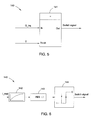
- the input terminal In of the comparator element 141 is used to receive a detected torque command G_trq.
- the detected torque command G_trq is related to the torque of the generator 13. It is understood that a value of the torque of the generator 13 can be obtained by torque sensors (not shown), for example.
- “1” refers to a high voltage control signal such as a 5 volts voltage signal
- 0 refers to a low voltage control signal such as a 0 volts voltage signal.
- the threshold terminal Thrsh of the comparator element 141 is used to receive a reference threshold value. In the embodiment of FIG. 5 , "0" is shown as an example.
- the output terminal Out of the comparator element 141 is used to output the switch signal according to the comparison of the detected torque command G_trq and the reference threshold value "0".
- the comparator element 141 will output a switch signal "0" to the switch implementation unit 150 so that any commands from the first compensation control unit 110 will be sent to the fundamental control unit 130.
- the comparator element 141 When the power conversion system 10 is in operation in the wind free state (second state) the detected torque command G_trq will be equal to zero (namely the power factor is equal to zero), thus the comparator element 141 will output a switch signal "1" to the switch implementation unit 150 so that any commands from the second compensation control unit 120 will be sent to the fundamental control unit 130.
- the comparator element 141 can be substituted by other kinds of algorithm elements with similar functions.
- the switch control unit 140 includes a filter element 142, an absolute value calculating element 143, and a hysteresis comparator element 144.
- the filter element 142 is used to receive and filter a detected current command I_real.
- the detected current command I_real is related to the root-mean-square value of the active current of the power conversion system 10.
- the active current of the power conversion system 10 can be obtained by use of current sensors (not shown), for example.
- the absolute value calculating element 143 is used to obtain the absolute value of the filtered detected current command I_real and output the absolute value to the hysteresis comparator element 144.
- the hysteresis comparator element 144 is used to output the switch signal according to the output value of the absolute value calculating element 143.
- the filter element 142, the absolute value calculating element 143, and the hysteresis comparator element 144 can be substituted with other kinds of algorithm elements with similar functions.
- the control method 200 may be programmed with software instructions stored in a non-transitory computer-readable medium, which, when executed by a processor, perform various steps of the control method 200.
- the computer-readable medium may include volatile and nonvolatile, removable and non-removable media implemented in any method or technology.
- the computer-readable medium includes, but is not limited to, RAM, ROM, EEPROM, flash memory, digital signal processor (DSP) or other memory technology, CD-ROM, digital versatile disks (DVD) or other optical storage, magnetic cassettes, magnetic tape, magnetic disk storage or other magnetic storage devices, or any other non-transitory medium which can be used to store the desired information and which can be accessed by an instruction execution system.
- DSP digital signal processor
- CD-ROM compact discs
- DVD digital versatile disks
- magnetic cassettes magnetic tape
- magnetic disk storage magnetic disk storage devices
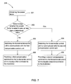
- the control method 200 may begin at block 201.
- a power factor of the control system 100 is obtained.
- the power factor is calculated using a detected torque command G_trq and a detected current command I_real, for example.
- the power factor may be obtained by other methods.
- the obtained power factor is used as a reference parameter related to the state of the power conversion system 10.
- the reference parameter may comprise a different parameter.
- the reference parameter comprises active power.
- the obtained power factor (here means absolute value) is compared with zero (such as described with respect to the embodiment of FIG. 5 ) or a determined value (such as described with respect to the embodiment of FIG. 6 ), such as 0.2. If the obtained power factor is not equal to zero or is greater than the determined value, the power conversion system 10 is operating in the first state, and then the process goes to the block 203. If the obtained power factor is equal to zero or is less than the determined value, the power conversion system 10 is operating in the second state, and then the process goes to the block 204.
- Blocks 203 and 204 may be accomplished by either of the methods shown in FIGs. 5 and 6 or by any appropriate other technique.
- the fundamental control unit 130 is switched to communicate with the first compensation control unit 110.
- the fundamental control unit 130 is switched to communicate with the second compensation control unit 120.
- the first compensation control unit 110 provides a first compensation command to the fundamental control unit 130 which then supplies a first command to the modulator 300 to balance the neutral point voltage.
- the second compensation control unit 120 provides a second compensation command to the fundamental control unit 130 which then supplies a second command to the modulator 300 to balance the neutral point voltage.
- This control method 200 involves slightly more computation than embodiments using one compensation calculation and command but offers more flexibility and better performance as the type of compensation that is most useful under the first state is typically not the same as the type of compensation that is most useful under the second state applications.
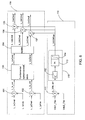
- FIGs. 8 and 9 illustrate exemplary, non-limiting embodiments of the first compensation control unit 110 and the second compensation control unit 120.
- the switch implementation unit 150 between the two compensation control units 110, 120 and the fundamental control unit 130 is not shown in FIGs. 8 and 9 .
- the fundamental control unit 130 is used to generate fundamental commands to be sent to the modulator 300 to control the converter assembly 19 to implement fundamental power conversion without necessarily balancing the neutral point voltage.
- the fundamental control unit 130 includes a first difference element 131, a second difference element 132, a fundamental current control block 133, and a dq/abc transformation block 134.
- the first difference element 131 is used to obtain an active current error signal L_Ix_err representative of the difference between a real active current command L_IxCmd and a feedback active current command L_IxFbk in dq coordinates.
- the second difference element 132 is used to obtain a reactive current error signal L_Iy_err representative of the difference between a real reactive current command L_IyCmd and a feedback reactive current command L_IyFbk in dq coordinates. It is understood that the real active current command L_IxCmd, the feedback active current command L_IxFbk, the real reactive current command L_IyCmd, and the feedback reactive current command L_IyFbk can be obtained by obtaining current values from current sensors at the output of the power conversion system and performing calculations on those current values.
- the fundamental current control block 133 is used to convert the active current error signal L_Ix_err and the reactive current error signal L_Iy_err to a corresponding active modulating command L_Uxcmd and a corresponding reactive modulating command L_Uxcmd. These modulating commands are used to modulate the duty cycle of the PWM signal of the modulator 300 to control the converter assembly 19. It is understood that the fundamental current control block 133 can use any appropriate method to implement the above function, such as a proportional integral (PI) regulator or a proportional integral differential (PID) regulator, for example.
- PI proportional integral
- PID proportional integral differential
- the dq/abc transformation block 134 is used to transform the active modulating command L_Uxcmd and reactive modulating command L_Uxcmd in dq coordinates to corresponding fundamental modulating commands L_UaCmd, L_UbCmd, and L_UcCmd in abc coordinates.
- the dq/abc transformation block 134 implements Park's transformation algorithm to transform signals from dq coordinates to abc coordinates.
- the commands L_UaCmd, L_UbCmd, L_UcCmd can directly modulate the duty cycle of the PWM signal of the modulator 300 to control the converter assembly 19 to implement fundamental power conversion.
- the first compensation control unit 110 includes a third difference element 111 and a neutral point voltage regulator 115.
- the third difference element 111 is used to obtain a voltage error signal L_Vdc_err representative of the neutral point voltage imbalance ⁇ which is calculated from the difference between a feedback voltage command Vdc1_Fbk on the capacitor C1 and a feedback voltage command Vdc2_Fbk on the capacitor C2.
- the neutral point voltage regulator 115 receives the voltage error signal L_Vdc_err and produces a fundamental compensation command L_DCOffSet (injected DC offset) for driving the voltage error signal L_Vdc_err towards zero.
- the neutral point voltage regulator 115 may include a filter element 112 and a PI regulator 113 combined with a limiter 114. In other embodiments, the neutral point voltage regulator 115 may use other elements and/or algorithms to obtain the fundamental compensation command L_DCOffSet.
- the fundamental compensation command L_DCOffSet as the first compensation command (also DC injection signal) is injected to the three summation elements 135, 136, and 137.
- three phase commands L_UaCmd', L_UbCmd', and L_UcCmd' are respectively produced from the three summation elements 135, 136, and 137 to modulate the duty cycle of the PWM signal of the modulator 300 to control the converter assembly 19 to implement fundamental power conversion while balancing the neutral point voltage.
- the neutral point current I dcM can be determined according to the following formula: I dcM ⁇ 4 ⁇ 3 ⁇ ⁇ 1 - ⁇ 2 ⁇ ⁇ ⁇ P active V dc ⁇ 1 MI G - 1 MI L + 4 ⁇ 3 ⁇ ⁇ 1 - ⁇ 2 ⁇ ⁇ ⁇ P active V dc ⁇ 1 MI G
- P active is the active power of the power conversion system 10
- MI G is the modulation index of the source-side converter 14
- MI L is the modulation index of the line-side converter
- Vdc is the voltage of the DC link 17
- ⁇ is the injected DC offset generated from the first compensation control unit 110
- I out is output
- the first compensation control unit 110 works for balancing the neutral point voltage when the power conversion system 10 is in operation in a normal operation state but does not work well for balancing the neutral point voltage when the power conversion system 10 is in operation in the wind free state.
- the first compensation control unit 110 cannot work well for balancing the neutral point voltage when the power conversion system 10 is in operation in the low power factor state, but can work well for balancing the neutral point voltage when the power conversion system 10 is in operation in the high power factor state.
- the first compensation control unit 110 may be suitable for balancing the neutral point voltage when the power conversion system 10 is in operation in the first state.
- the second compensation control unit 120 includes a fourth difference element 121 and a neutral point voltage regulator 125 having a filter element 122 and a PI regulator 123 combined with a limiter 124.
- the fourth difference element 121 and the neutral point voltage regulator 125 have the same function as the third difference element 112 and the neutral point voltage regulator 115 and are thus not described here again.
- the difference between the second compensation control unit 120 and the first compensation control unit 110 is that the second compensation control unit 120 further includes an odd harmonics signal generator 128 used to transform the DC injection signal L_DCOffSet to odd harmonics signals L_Ux and L_Uy in dq coordinates as the second compensation command.
- an odd harmonics signal generator 128 used to transform the DC injection signal L_DCOffSet to odd harmonics signals L_Ux and L_Uy in dq coordinates as the second compensation command.
- the odd harmonics signal generator 128 includes a first multiplying element 126 and a second multiplying element 127.
- the first multiplying element 126 is used to obtain the odd harmonics signal L_Ux by multiplying the DC injection signal L_DCOffSet and a first angular signal cos(-3( ⁇ t+ ⁇ n )).
- the second multiplying element 127 is used to obtain the odd harmonics signal L_Uy by multiplying the DC injection signal L_DCOffSet and a second angular signal sin(-3( ⁇ t+ ⁇ n )).
- ⁇ 2 ⁇ f
- ⁇ n (n-1)( ⁇ + ⁇ /2(n-1))/n
- ⁇ atan(L_ Uycmd/L_ Uxcmd)
- ⁇ n injected harmonic angle
- n order of harmonic injected in dq coordinate
- f represents frequency
- t time.
- n can be other odd numbers, such as 5, 7, 9, etc.
- two summation elements 138 and 139 are further used through the transmitting path of the active modulating command L_Uxcmd and the reactive modulating command L_Uycmd respectively in the fundamental control unit 110.
- the summation elements 138 and 139 respectively generate two sum commands L'_Uxcmd and L'_Uycmd by summing the command L_Uxcmd and the command L_Ux, and summing the command L_Uycmd and the command L_Uy.
- the dq/abc transformation block 134 is used to transform the commands L'_Uxcmd and L'_Uycmd in dq coordinates to corresponding three phase commands L_UaCmd', L_UbCmd', and L_UcCmd', in abc coordinates.
- the three phase commands L_UaCmd', L_UbCmd', and L_UcCmd' can be used to modulate the duty cycle of the PWM signal of the modulator 300 to control the converter assembly 19 to implement fundamental power conversion operation from the generator 13 to the grid 16 together with balancing the neutral point voltage.
- FIG. 10 a diagram of the neutral point (Mid-point) current I dcM , as a function of a neutral point voltage imbalance ⁇ using the second compensation unit 120 and working in the normal operation state is shown.
- a wave 301 is related to the state that the power factor (PF) is equal to 1.0
- a wave 302 is related to the state that the power factor (PF) is equal to 0.9
- a wave 303 is related to the state that the power factor (PF) is equal to 0.5.
- FIG. 11 a diagram of the neutral point current I dcM , as a function of a neutral point voltage imbalance ⁇ using the second compensation unit 120 and working in the wind free state is shown.
- a wave 401 is related to the state that the fundamental voltage magnitude (A1) is equal to 0.9
- a wave 402 is related to the state that the fundamental voltage magnitude (A1) is equal to 0.8
- a wave 403 is related to the state that the fundamental voltage magnitude (A1) is equal to 0.6.
- FIG. 10 illustrates that when the power conversion system 10 is in operation in the wind free state, the second compensation unit 120 can work well for balancing the neutral point voltage. According to FIGs.
- the second compensation control unit 120 is thus suitable for balancing the neutral point voltage when the power conversion system 10 is in operation in the second state.
- selection of the proper state is beneficial to obtaining the best control response among the first and second compensation signals.
Landscapes
- Engineering & Computer Science (AREA)
- Power Engineering (AREA)
- Inverter Devices (AREA)
- Control Of Eletrric Generators (AREA)
Applications Claiming Priority (1)
| Application Number | Priority Date | Filing Date | Title |
|---|---|---|---|
| CN201110373940.1A CN103138594B (zh) | 2011-11-22 | 2011-11-22 | 中点箝位式变流器的控制系统及控制方法及补偿控制单元 |
Publications (3)
| Publication Number | Publication Date |
|---|---|
| EP2597768A2 true EP2597768A2 (de) | 2013-05-29 |
| EP2597768A3 EP2597768A3 (de) | 2017-08-09 |
| EP2597768B1 EP2597768B1 (de) | 2019-08-07 |
Family
ID=47215438
Family Applications (1)
| Application Number | Title | Priority Date | Filing Date |
|---|---|---|---|
| EP12193465.7A Active EP2597768B1 (de) | 2011-11-22 | 2012-11-20 | Steuersystem für einen Neutralpunktklemmenumrichter sowie Steuerverfahren und Ausgleichseinheit |
Country Status (4)
| Country | Link |
|---|---|
| US (1) | US9083261B2 (de) |
| EP (1) | EP2597768B1 (de) |
| CN (1) | CN103138594B (de) |
| DK (1) | DK2597768T3 (de) |
Cited By (2)
| Publication number | Priority date | Publication date | Assignee | Title |
|---|---|---|---|---|
| EP2827490A1 (de) * | 2013-07-03 | 2015-01-21 | General Electric Company | System und Verfahren zur Gleichtaktspannungsinjektion |
| EP2849331A1 (de) * | 2013-09-11 | 2015-03-18 | ABB Oy | Verfahren und Vorrichtung zum Ausgleich von Spannungen des Gleichstromzwischenkreises eines mehrstufigen Umrichters |
Families Citing this family (18)
| Publication number | Priority date | Publication date | Assignee | Title |
|---|---|---|---|---|
| CN103138595B (zh) * | 2011-11-22 | 2016-05-25 | 通用电气公司 | 中点箝位式变流器的控制系统及控制方法 |
| CN104348342B (zh) * | 2013-08-02 | 2019-05-31 | 通用电气公司 | 电能变换系统和方法 |
| EP2881811B1 (de) | 2013-12-06 | 2018-08-01 | General Electric Technology GmbH | Steuerungsvorrichtung für einen spannungsgespeisten Umrichter mit einem redundanten System bestehend aus zwei Steuervorrichtungen |
| EP3128636B1 (de) * | 2014-03-31 | 2019-04-24 | Mitsubishi Electric Corporation | Oberschwingungsstromkompensationsvorrichtung und klimaanlagensystem |
| CN105337299B (zh) * | 2014-05-30 | 2019-05-28 | 通用电气公司 | 用于控制连接到弱电网上的功率发生系统的系统和方法 |
| US9590521B2 (en) * | 2014-07-28 | 2017-03-07 | Hamilton Sundstrand Corporation | Power converters for aircraft starter/generators |
| JP6342293B2 (ja) * | 2014-10-20 | 2018-06-13 | 株式会社東芝 | 中性点クランプ形電力変換装置およびその制御方法 |
| CN104333252A (zh) * | 2014-10-27 | 2015-02-04 | 合康变频科技(武汉)有限公司 | 一种基于六次谐波注入的逆变器中点电压控制方法及系统 |
| US9755545B2 (en) | 2014-11-21 | 2017-09-05 | General Electric Company | System and method for unified common mode voltage injection |
| JP6426462B2 (ja) * | 2014-12-24 | 2018-11-21 | 株式会社東芝 | 電力変換装置およびその制御方法 |
| US9634579B2 (en) * | 2015-04-03 | 2017-04-25 | Hamilton Sundstrand Corporation | Systems and methods for controlling inverters |
| CN107317494B (zh) * | 2017-08-09 | 2019-11-29 | 科华恒盛股份有限公司 | 一种三电平变换器及其母线中点的平衡控制方法及装置 |
| US10826381B2 (en) | 2018-04-17 | 2020-11-03 | Abb Schweiz Ag | Method and control system for zero-sequence current compensation for ground current reduction |
| CN112005482B (zh) * | 2018-04-27 | 2023-12-12 | 东芝三菱电机产业系统株式会社 | 三电平电力变换装置、三电平电力变换装置的控制方法及存储介质 |
| US10536003B1 (en) * | 2018-07-20 | 2020-01-14 | University Of South Florida | Power system stabilizer for voltage source converters |
| CN108880308B (zh) * | 2018-07-27 | 2020-10-09 | 深圳市盛弘电气股份有限公司 | 一种三电平逆变器的直流母线平衡方法及系统 |
| US11258387B1 (en) * | 2020-10-30 | 2022-02-22 | General Electric Renovables Espana, S.L. | System and method for neutral point balancing for back-to-back voltage source converters |
| CN118264107A (zh) * | 2024-03-13 | 2024-06-28 | 深圳供电局有限公司 | 储能主动能量支撑系统及其控制方法和计算机设备 |
Family Cites Families (15)
| Publication number | Priority date | Publication date | Assignee | Title |
|---|---|---|---|---|
| JP2888104B2 (ja) * | 1993-09-01 | 1999-05-10 | 株式会社日立製作所 | 電力変換装置 |
| JP3186369B2 (ja) | 1993-09-09 | 2001-07-11 | 富士電機株式会社 | 3レベルインバータの制御回路 |
| JP3248321B2 (ja) | 1993-11-10 | 2002-01-21 | 富士電機株式会社 | 3レベルインバータの制御回路 |
| JPH08331857A (ja) * | 1995-05-30 | 1996-12-13 | Meidensha Corp | 中性点クランプ形インバータ |
| US5790396A (en) * | 1995-12-19 | 1998-08-04 | Kabushiki Kaisha Toshiba | Neutral point clamped (NPC) inverter control system |
| US6058031A (en) | 1997-10-23 | 2000-05-02 | General Electric Company | Five level high power motor drive converter and control system |
| US6031738A (en) | 1998-06-16 | 2000-02-29 | Wisconsin Alumni Research Foundation | DC bus voltage balancing and control in multilevel inverters |
| US6534949B2 (en) | 2001-03-29 | 2003-03-18 | General Electric Company | Motor drive converter and method with neutral point drift compensation |
| US7050311B2 (en) * | 2003-11-25 | 2006-05-23 | Electric Power Research Institute, Inc. | Multilevel converter based intelligent universal transformer |
| CN100468938C (zh) * | 2005-03-01 | 2009-03-11 | 广东明阳龙源电力电子有限公司 | 一种三电平逆变器的控制系统及方法 |
| US7495938B2 (en) | 2005-04-15 | 2009-02-24 | Rockwell Automation Technologies, Inc. | DC voltage balance control for three-level NPC power converters with even-order harmonic elimination scheme |
| US7573732B2 (en) | 2007-05-25 | 2009-08-11 | General Electric Company | Protective circuit and method for multi-level converter |
| EP2160828B1 (de) | 2007-06-01 | 2016-05-04 | DRS Power & Control Technologies, Inc. | Vierpolneutralpunktgeklemmter dreiphasenumrichter mit nullgleichtaktspannungsausgang |
| CN101707388B (zh) * | 2009-11-30 | 2011-12-21 | 浙江大学 | 一种燃料电池不间断电源装置 |
| CN102013824A (zh) * | 2010-09-21 | 2011-04-13 | 深圳市大族激光科技股份有限公司 | 用于抑制三电平逆变器中点电位飘移的控制器 |
-
2011
- 2011-11-22 CN CN201110373940.1A patent/CN103138594B/zh active Active
-
2012
- 2012-11-20 DK DK12193465T patent/DK2597768T3/da active
- 2012-11-20 EP EP12193465.7A patent/EP2597768B1/de active Active
- 2012-11-21 US US13/682,996 patent/US9083261B2/en active Active
Non-Patent Citations (1)
| Title |
|---|
| None |
Cited By (4)
| Publication number | Priority date | Publication date | Assignee | Title |
|---|---|---|---|---|
| EP2827490A1 (de) * | 2013-07-03 | 2015-01-21 | General Electric Company | System und Verfahren zur Gleichtaktspannungsinjektion |
| US9634576B2 (en) | 2013-07-03 | 2017-04-25 | General Electric Company | System and method for unified common mode voltage injection |
| EP2849331A1 (de) * | 2013-09-11 | 2015-03-18 | ABB Oy | Verfahren und Vorrichtung zum Ausgleich von Spannungen des Gleichstromzwischenkreises eines mehrstufigen Umrichters |
| US9595864B2 (en) | 2013-09-11 | 2017-03-14 | Abb Technology Oy | Method and apparatus for balancing voltages of multi-level inverter DC link |
Also Published As
| Publication number | Publication date |
|---|---|
| EP2597768A3 (de) | 2017-08-09 |
| CN103138594A (zh) | 2013-06-05 |
| US20130128632A1 (en) | 2013-05-23 |
| DK2597768T3 (da) | 2019-11-04 |
| CN103138594B (zh) | 2016-03-02 |
| US9083261B2 (en) | 2015-07-14 |
| EP2597768B1 (de) | 2019-08-07 |
Similar Documents
| Publication | Publication Date | Title |
|---|---|---|
| EP2597768B1 (de) | Steuersystem für einen Neutralpunktklemmenumrichter sowie Steuerverfahren und Ausgleichseinheit | |
| JP6218961B2 (ja) | 多重巻線電動機駆動制御装置 | |
| US9071084B2 (en) | Neutral point clamped converter control systems and methods | |
| EP2491644B1 (de) | System und verfahren für den ausgleich des eingangsspannungsungleichgewichts bei mehrstufigen wechselrichtern oder dergleichen | |
| US9634576B2 (en) | System and method for unified common mode voltage injection | |
| Nagarajan et al. | Staircase multicarrier SPWM technique for nine level cascaded inverter | |
| CN117955167B (zh) | 构网型电压源变流器系统及多目标控制方法 | |
| CN119675485B (zh) | 基于二极管箝位型三电平并网逆变器的中点电位控制方法及相关装置 | |
| Ajami et al. | Design and control of a grid tied 6-switch converter for two independent low power wind energy resources based on PMSGs with MPPT capability | |
| Yuan et al. | Direct-switch duty-cycle control of grid-connected n-level neutral-point-clamped converter | |
| US11146181B2 (en) | Control method and apparatus for common-mode modulated wave of single-phase five-level inverter | |
| Jeong et al. | An interleaving scheme for DC-link current ripple reduction in parallel-connected generator systems | |
| KR20190060966A (ko) | 전력변환회로를 제어하는 제어회로, 이 제어회로를 구비한 인버터 장치 및 이 인버터 장치를 구비한 계통연계 인버터 시스템 | |
| Mansour et al. | Application of backstepping to the virtual flux direct power control of five-level three-phase shunt active power filter | |
| Pulikanti et al. | Control of five-level flying capacitor based active-neutral-point-clamped converter for grid connected wind energy applications | |
| Jayasingha et al. | Cascade multilevel static synchronous compensator configuration for wind farms | |
| Mademlis et al. | Combined voltage balancing techniques of the DC link in five-level medium voltage NPC back-to-back converters for offshore renewable generation | |
| Yousefpour et al. | Using a Z-source inverter as rotor side converter in doubly-fed induction generator wind energy conversion system | |
| Onizuka et al. | Control of a 7-levels PUC based three phase inverter through vector current control and hybrid modulation | |
| Pushparani et al. | Simulation and Analysis of SVHM Technique for DCMLI under Transient Conditions with Non-Linear Loads | |
| Mirazimi et al. | Space vector PWM method for two-phase three-leg inverters | |
| Hassanabad et al. | Design and simulation of space vector pulse width modulation inverter based transformer-less in small wind turbines | |
| Bayhan et al. | Sliding-mode-control strategy for single-phase grid-connected three-level NPC quasi-z-source inverters with constant switching frequency | |
| Jayasinghe et al. | A dual inverter with integrated energy storage for wind power systems | |
| Fadaeian et al. | A Fast Processing Discontinuous Control Strategy for Vienna Rectifier |
Legal Events
| Date | Code | Title | Description |
|---|---|---|---|
| PUAI | Public reference made under article 153(3) epc to a published international application that has entered the european phase |
Free format text: ORIGINAL CODE: 0009012 |
|
| AK | Designated contracting states |
Kind code of ref document: A2 Designated state(s): AL AT BE BG CH CY CZ DE DK EE ES FI FR GB GR HR HU IE IS IT LI LT LU LV MC MK MT NL NO PL PT RO RS SE SI SK SM TR |
|
| AX | Request for extension of the european patent |
Extension state: BA ME |
|
| PUAL | Search report despatched |
Free format text: ORIGINAL CODE: 0009013 |
|
| AK | Designated contracting states |
Kind code of ref document: A3 Designated state(s): AL AT BE BG CH CY CZ DE DK EE ES FI FR GB GR HR HU IE IS IT LI LT LU LV MC MK MT NL NO PL PT RO RS SE SI SK SM TR |
|
| AX | Request for extension of the european patent |
Extension state: BA ME |
|
| RIC1 | Information provided on ipc code assigned before grant |
Ipc: H02M 7/487 20070101ALI20170706BHEP Ipc: H02M 7/483 20070101AFI20170706BHEP |
|
| STAA | Information on the status of an ep patent application or granted ep patent |
Free format text: STATUS: REQUEST FOR EXAMINATION WAS MADE |
|
| 17P | Request for examination filed |
Effective date: 20180209 |
|
| RBV | Designated contracting states (corrected) |
Designated state(s): AL AT BE BG CH CY CZ DE DK EE ES FI FR GB GR HR HU IE IS IT LI LT LU LV MC MK MT NL NO PL PT RO RS SE SI SK SM TR |
|
| GRAP | Despatch of communication of intention to grant a patent |
Free format text: ORIGINAL CODE: EPIDOSNIGR1 |
|
| STAA | Information on the status of an ep patent application or granted ep patent |
Free format text: STATUS: GRANT OF PATENT IS INTENDED |
|
| INTG | Intention to grant announced |
Effective date: 20190301 |
|
| GRAS | Grant fee paid |
Free format text: ORIGINAL CODE: EPIDOSNIGR3 |
|
| GRAA | (expected) grant |
Free format text: ORIGINAL CODE: 0009210 |
|
| STAA | Information on the status of an ep patent application or granted ep patent |
Free format text: STATUS: THE PATENT HAS BEEN GRANTED |
|
| AK | Designated contracting states |
Kind code of ref document: B1 Designated state(s): AL AT BE BG CH CY CZ DE DK EE ES FI FR GB GR HR HU IE IS IT LI LT LU LV MC MK MT NL NO PL PT RO RS SE SI SK SM TR |
|
| REG | Reference to a national code |
Ref country code: GB Ref legal event code: FG4D |
|
| REG | Reference to a national code |
Ref country code: CH Ref legal event code: EP Ref country code: AT Ref legal event code: REF Ref document number: 1165346 Country of ref document: AT Kind code of ref document: T Effective date: 20190815 |
|
| REG | Reference to a national code |
Ref country code: IE Ref legal event code: FG4D |
|
| REG | Reference to a national code |
Ref country code: DE Ref legal event code: R096 Ref document number: 602012062638 Country of ref document: DE |
|
| REG | Reference to a national code |
Ref country code: DK Ref legal event code: T3 Effective date: 20191029 |
|
| REG | Reference to a national code |
Ref country code: NL Ref legal event code: MP Effective date: 20190807 |
|
| REG | Reference to a national code |
Ref country code: LT Ref legal event code: MG4D |
|
| PG25 | Lapsed in a contracting state [announced via postgrant information from national office to epo] |
Ref country code: FI Free format text: LAPSE BECAUSE OF FAILURE TO SUBMIT A TRANSLATION OF THE DESCRIPTION OR TO PAY THE FEE WITHIN THE PRESCRIBED TIME-LIMIT Effective date: 20190807 Ref country code: PT Free format text: LAPSE BECAUSE OF FAILURE TO SUBMIT A TRANSLATION OF THE DESCRIPTION OR TO PAY THE FEE WITHIN THE PRESCRIBED TIME-LIMIT Effective date: 20191209 Ref country code: HR Free format text: LAPSE BECAUSE OF FAILURE TO SUBMIT A TRANSLATION OF THE DESCRIPTION OR TO PAY THE FEE WITHIN THE PRESCRIBED TIME-LIMIT Effective date: 20190807 Ref country code: SE Free format text: LAPSE BECAUSE OF FAILURE TO SUBMIT A TRANSLATION OF THE DESCRIPTION OR TO PAY THE FEE WITHIN THE PRESCRIBED TIME-LIMIT Effective date: 20190807 Ref country code: NO Free format text: LAPSE BECAUSE OF FAILURE TO SUBMIT A TRANSLATION OF THE DESCRIPTION OR TO PAY THE FEE WITHIN THE PRESCRIBED TIME-LIMIT Effective date: 20191107 Ref country code: BG Free format text: LAPSE BECAUSE OF FAILURE TO SUBMIT A TRANSLATION OF THE DESCRIPTION OR TO PAY THE FEE WITHIN THE PRESCRIBED TIME-LIMIT Effective date: 20191107 Ref country code: NL Free format text: LAPSE BECAUSE OF FAILURE TO SUBMIT A TRANSLATION OF THE DESCRIPTION OR TO PAY THE FEE WITHIN THE PRESCRIBED TIME-LIMIT Effective date: 20190807 Ref country code: LT Free format text: LAPSE BECAUSE OF FAILURE TO SUBMIT A TRANSLATION OF THE DESCRIPTION OR TO PAY THE FEE WITHIN THE PRESCRIBED TIME-LIMIT Effective date: 20190807 |
|
| REG | Reference to a national code |
Ref country code: AT Ref legal event code: MK05 Ref document number: 1165346 Country of ref document: AT Kind code of ref document: T Effective date: 20190807 |
|
| PG25 | Lapsed in a contracting state [announced via postgrant information from national office to epo] |
Ref country code: GR Free format text: LAPSE BECAUSE OF FAILURE TO SUBMIT A TRANSLATION OF THE DESCRIPTION OR TO PAY THE FEE WITHIN THE PRESCRIBED TIME-LIMIT Effective date: 20191108 Ref country code: ES Free format text: LAPSE BECAUSE OF FAILURE TO SUBMIT A TRANSLATION OF THE DESCRIPTION OR TO PAY THE FEE WITHIN THE PRESCRIBED TIME-LIMIT Effective date: 20190807 Ref country code: AL Free format text: LAPSE BECAUSE OF FAILURE TO SUBMIT A TRANSLATION OF THE DESCRIPTION OR TO PAY THE FEE WITHIN THE PRESCRIBED TIME-LIMIT Effective date: 20190807 Ref country code: LV Free format text: LAPSE BECAUSE OF FAILURE TO SUBMIT A TRANSLATION OF THE DESCRIPTION OR TO PAY THE FEE WITHIN THE PRESCRIBED TIME-LIMIT Effective date: 20190807 Ref country code: IS Free format text: LAPSE BECAUSE OF FAILURE TO SUBMIT A TRANSLATION OF THE DESCRIPTION OR TO PAY THE FEE WITHIN THE PRESCRIBED TIME-LIMIT Effective date: 20191207 Ref country code: RS Free format text: LAPSE BECAUSE OF FAILURE TO SUBMIT A TRANSLATION OF THE DESCRIPTION OR TO PAY THE FEE WITHIN THE PRESCRIBED TIME-LIMIT Effective date: 20190807 |
|
| PG25 | Lapsed in a contracting state [announced via postgrant information from national office to epo] |
Ref country code: TR Free format text: LAPSE BECAUSE OF FAILURE TO SUBMIT A TRANSLATION OF THE DESCRIPTION OR TO PAY THE FEE WITHIN THE PRESCRIBED TIME-LIMIT Effective date: 20190807 |
|
| PG25 | Lapsed in a contracting state [announced via postgrant information from national office to epo] |
Ref country code: PL Free format text: LAPSE BECAUSE OF FAILURE TO SUBMIT A TRANSLATION OF THE DESCRIPTION OR TO PAY THE FEE WITHIN THE PRESCRIBED TIME-LIMIT Effective date: 20190807 Ref country code: EE Free format text: LAPSE BECAUSE OF FAILURE TO SUBMIT A TRANSLATION OF THE DESCRIPTION OR TO PAY THE FEE WITHIN THE PRESCRIBED TIME-LIMIT Effective date: 20190807 Ref country code: AT Free format text: LAPSE BECAUSE OF FAILURE TO SUBMIT A TRANSLATION OF THE DESCRIPTION OR TO PAY THE FEE WITHIN THE PRESCRIBED TIME-LIMIT Effective date: 20190807 Ref country code: RO Free format text: LAPSE BECAUSE OF FAILURE TO SUBMIT A TRANSLATION OF THE DESCRIPTION OR TO PAY THE FEE WITHIN THE PRESCRIBED TIME-LIMIT Effective date: 20190807 Ref country code: IT Free format text: LAPSE BECAUSE OF FAILURE TO SUBMIT A TRANSLATION OF THE DESCRIPTION OR TO PAY THE FEE WITHIN THE PRESCRIBED TIME-LIMIT Effective date: 20190807 |
|
| PG25 | Lapsed in a contracting state [announced via postgrant information from national office to epo] |
Ref country code: CZ Free format text: LAPSE BECAUSE OF FAILURE TO SUBMIT A TRANSLATION OF THE DESCRIPTION OR TO PAY THE FEE WITHIN THE PRESCRIBED TIME-LIMIT Effective date: 20190807 Ref country code: SK Free format text: LAPSE BECAUSE OF FAILURE TO SUBMIT A TRANSLATION OF THE DESCRIPTION OR TO PAY THE FEE WITHIN THE PRESCRIBED TIME-LIMIT Effective date: 20190807 Ref country code: IS Free format text: LAPSE BECAUSE OF FAILURE TO SUBMIT A TRANSLATION OF THE DESCRIPTION OR TO PAY THE FEE WITHIN THE PRESCRIBED TIME-LIMIT Effective date: 20200224 Ref country code: SM Free format text: LAPSE BECAUSE OF FAILURE TO SUBMIT A TRANSLATION OF THE DESCRIPTION OR TO PAY THE FEE WITHIN THE PRESCRIBED TIME-LIMIT Effective date: 20190807 |
|
| REG | Reference to a national code |
Ref country code: DE Ref legal event code: R097 Ref document number: 602012062638 Country of ref document: DE |
|
| REG | Reference to a national code |
Ref country code: CH Ref legal event code: PL |
|
| PLBE | No opposition filed within time limit |
Free format text: ORIGINAL CODE: 0009261 |
|
| STAA | Information on the status of an ep patent application or granted ep patent |
Free format text: STATUS: NO OPPOSITION FILED WITHIN TIME LIMIT |
|
| PG2D | Information on lapse in contracting state deleted |
Ref country code: IS |
|
| PG25 | Lapsed in a contracting state [announced via postgrant information from national office to epo] |
Ref country code: LU Free format text: LAPSE BECAUSE OF NON-PAYMENT OF DUE FEES Effective date: 20191120 Ref country code: MC Free format text: LAPSE BECAUSE OF FAILURE TO SUBMIT A TRANSLATION OF THE DESCRIPTION OR TO PAY THE FEE WITHIN THE PRESCRIBED TIME-LIMIT Effective date: 20190807 Ref country code: LI Free format text: LAPSE BECAUSE OF NON-PAYMENT OF DUE FEES Effective date: 20191130 Ref country code: CH Free format text: LAPSE BECAUSE OF NON-PAYMENT OF DUE FEES Effective date: 20191130 |
|
| 26N | No opposition filed |
Effective date: 20200603 |
|
| REG | Reference to a national code |
Ref country code: BE Ref legal event code: MM Effective date: 20191130 |
|
| PG25 | Lapsed in a contracting state [announced via postgrant information from national office to epo] |
Ref country code: SI Free format text: LAPSE BECAUSE OF FAILURE TO SUBMIT A TRANSLATION OF THE DESCRIPTION OR TO PAY THE FEE WITHIN THE PRESCRIBED TIME-LIMIT Effective date: 20190807 |
|
| GBPC | Gb: european patent ceased through non-payment of renewal fee |
Effective date: 20191120 |
|
| PG25 | Lapsed in a contracting state [announced via postgrant information from national office to epo] |
Ref country code: GB Free format text: LAPSE BECAUSE OF NON-PAYMENT OF DUE FEES Effective date: 20191120 Ref country code: IE Free format text: LAPSE BECAUSE OF NON-PAYMENT OF DUE FEES Effective date: 20191120 Ref country code: FR Free format text: LAPSE BECAUSE OF NON-PAYMENT OF DUE FEES Effective date: 20191130 |
|
| PG25 | Lapsed in a contracting state [announced via postgrant information from national office to epo] |
Ref country code: BE Free format text: LAPSE BECAUSE OF NON-PAYMENT OF DUE FEES Effective date: 20191130 |
|
| PG25 | Lapsed in a contracting state [announced via postgrant information from national office to epo] |
Ref country code: CY Free format text: LAPSE BECAUSE OF FAILURE TO SUBMIT A TRANSLATION OF THE DESCRIPTION OR TO PAY THE FEE WITHIN THE PRESCRIBED TIME-LIMIT Effective date: 20190807 |
|
| PG25 | Lapsed in a contracting state [announced via postgrant information from national office to epo] |
Ref country code: MT Free format text: LAPSE BECAUSE OF FAILURE TO SUBMIT A TRANSLATION OF THE DESCRIPTION OR TO PAY THE FEE WITHIN THE PRESCRIBED TIME-LIMIT Effective date: 20190807 Ref country code: HU Free format text: LAPSE BECAUSE OF FAILURE TO SUBMIT A TRANSLATION OF THE DESCRIPTION OR TO PAY THE FEE WITHIN THE PRESCRIBED TIME-LIMIT; INVALID AB INITIO Effective date: 20121120 |
|
| PG25 | Lapsed in a contracting state [announced via postgrant information from national office to epo] |
Ref country code: MK Free format text: LAPSE BECAUSE OF FAILURE TO SUBMIT A TRANSLATION OF THE DESCRIPTION OR TO PAY THE FEE WITHIN THE PRESCRIBED TIME-LIMIT Effective date: 20190807 |
|
| P01 | Opt-out of the competence of the unified patent court (upc) registered |
Effective date: 20230530 |
|
| REG | Reference to a national code |
Ref country code: DE Ref legal event code: R082 Ref document number: 602012062638 Country of ref document: DE Representative=s name: ZIMMERMANN & PARTNER PATENTANWAELTE MBB, DE Ref country code: DE Ref legal event code: R082 Ref document number: 602012062638 Country of ref document: DE Ref country code: DE Ref legal event code: R081 Ref document number: 602012062638 Country of ref document: DE Owner name: GENERAL ELECTRIC RENOVABLES ESPANA, S.L., ES Free format text: FORMER OWNER: GENERAL ELECTRIC COMPANY, SCHENECTADY, NY, US |
|
| REG | Reference to a national code |
Ref country code: DE Ref legal event code: R082 Ref document number: 602012062638 Country of ref document: DE Representative=s name: ZIMMERMANN & PARTNER PATENTANWAELTE MBB, DE |
|
| PGFP | Annual fee paid to national office [announced via postgrant information from national office to epo] |
Ref country code: DE Payment date: 20251022 Year of fee payment: 14 |
|
| PGFP | Annual fee paid to national office [announced via postgrant information from national office to epo] |
Ref country code: DK Payment date: 20251022 Year of fee payment: 14 |