EP2597744B1 - Cable closure - Google Patents
Cable closure Download PDFInfo
- Publication number
- EP2597744B1 EP2597744B1 EP11190438.9A EP11190438A EP2597744B1 EP 2597744 B1 EP2597744 B1 EP 2597744B1 EP 11190438 A EP11190438 A EP 11190438A EP 2597744 B1 EP2597744 B1 EP 2597744B1
- Authority
- EP
- European Patent Office
- Prior art keywords
- cable closure
- cable
- interior
- shells
- closure
- Prior art date
- Legal status (The legal status is an assumption and is not a legal conclusion. Google has not performed a legal analysis and makes no representation as to the accuracy of the status listed.)
- Active
Links
- 230000004888 barrier function Effects 0.000 claims description 77
- 238000007789 sealing Methods 0.000 claims description 75
- 238000003780 insertion Methods 0.000 claims description 38
- 230000037431 insertion Effects 0.000 claims description 38
- 210000005252 bulbus oculi Anatomy 0.000 description 6
- 230000000694 effects Effects 0.000 description 6
- 239000000463 material Substances 0.000 description 5
- 239000000835 fiber Substances 0.000 description 2
- 239000000499 gel Substances 0.000 description 2
- 239000003566 sealing material Substances 0.000 description 2
- RYGMFSIKBFXOCR-UHFFFAOYSA-N Copper Chemical compound [Cu] RYGMFSIKBFXOCR-UHFFFAOYSA-N 0.000 description 1
- 230000000712 assembly Effects 0.000 description 1
- 238000000429 assembly Methods 0.000 description 1
- 239000004020 conductor Substances 0.000 description 1
- 229910052802 copper Inorganic materials 0.000 description 1
- 239000010949 copper Substances 0.000 description 1
- 229920001296 polysiloxane Polymers 0.000 description 1
- 229920002635 polyurethane Polymers 0.000 description 1
- 239000004814 polyurethane Substances 0.000 description 1
Images


Classifications
-
- H—ELECTRICITY
- H02—GENERATION; CONVERSION OR DISTRIBUTION OF ELECTRIC POWER
- H02G—INSTALLATION OF ELECTRIC CABLES OR LINES, OR OF COMBINED OPTICAL AND ELECTRIC CABLES OR LINES
- H02G15/00—Cable fittings
- H02G15/013—Sealing means for cable inlets
-
- H—ELECTRICITY
- H02—GENERATION; CONVERSION OR DISTRIBUTION OF ELECTRIC POWER
- H02G—INSTALLATION OF ELECTRIC CABLES OR LINES, OR OF COMBINED OPTICAL AND ELECTRIC CABLES OR LINES
- H02G15/00—Cable fittings
- H02G15/08—Cable junctions
- H02G15/10—Cable junctions protected by boxes, e.g. by distribution, connection or junction boxes
- H02G15/113—Boxes split longitudinally in main cable direction
Definitions
- the present patent application relates to a cable closure in accordance with the preamble of claim 1.
- Cable closures are used in telecommunications cable networks for protecting spliced joints at connection points between telecommunications cables and for protecting branch points or splitting points of telecommunications cables.
- the cable closures are intended to ensure the continuity of the telecommunications cables as though the telecommunications cables had not been interrupted.
- the product catalog "Accessories for Fiber Optic Networks", Edition 1, page 75, Corning Cable Systems, year 2001” discloses cable closures firstly in the form of inline cable closures and secondly in the form of dome cable closures, which all have a housing that defines an interior of the cable closure and seals off the interior thereof from the outside.
- assemblies for connecting, namely for splicing, telecommunications conductors guided in telecommunications cables are arranged in the interior defined by the housing of the cable closure.
- the housing is formed by a dome-like covering body and by a sealing body, the sealing body defining cable insertion regions, which are sealed off on one side of the dome-like covering body and via which all of the cables can be inserted into the interior of the cable closure.
- cable insertion regions which are sealed off on two opposite sides of the covering body are formed for inserting cables into the interior of the cable closure, with the result that inline cable closures can be installed in one line with the cables.
- DE 20 2010 006 582 U1 discloses an inline cable closure, having a housing, which delimits an interior of the cable closure and seals off the cable closure toward the outside, the housing comprising a covering body, the covering body comprises shells and provides on mutually opposite sides of the same cable insertion regions for inserting cables into the interior of the cable closure and/or for passing cables out of the interior of the cable closure.
- U1 compressible and/or deformable sealing elements are positioned at the mutually opposite sides of the covering body in the region of the cable insertion regions of the shells, wherein each of the sealing elements is positioned between barrier walls of the respective shell, namely between a barrier wall facing the interior of the cable closure and a barrier wall remote from the interior of the cable closure.
- WO 99/56370 A1 discloses an inline cable closure with the features of the preamble of claim 1.
- the present patent application provides a novel cable closure having improved sealing properties.
- the embedded resilient fingers or flaps of the spring elements in combination with the embedded protrusions keep the compressible and/or deformable sealing element in place during operation or during testing of the cable closure over a wide temperature range.
- the embedded resilient fingers or flaps of the spring elements combination with the embedded protrusions decrease an axial sliding of the sealing element in longitudinal direction of the respective cable which may be caused by thermal expansion of the compressible and/or deformable sealing element. This minimizes the risk that the sealing elements become damaged during operation or testing and improves the sealing properties of the cable closure.
- the sealing elements in which the resilient fingers or flaps of the spring elements are embedded comprise adjacent to the embedded resilient fingers or flaps of each spring element recesses having a generally narrowing cross section. This improves further the sealing properties of the cable closure.
- the resilient fingers or flaps of the spring elements provide resilient fans, whereby the fans have a generally narrowing cross section. This improves further the sealing properties of the cable closure.
- the present invention relates to a cable closure 10 preferably for copper cables or fiber optic cables or hybrid cables, which in the preferred exemplary embodiment shown is an inline cable closure.
- the cable closure 10 comprises a housing which is formed by a covering body 13 composed of two shells 11 and 12.
- the shells 11 and 12 are half-shells and the half-shell 11 is a so-called lower half-shell and the half-shell 12 is a so-called upper half-shell of the covering body 13, which together define an interior 14 of the inline cable closure 10.
- Cable insertion regions 17 are formed on mutually opposite sides 15 and 16 of the inline cable closure 10 or the covering body 13, with it being possible for cables to be inserted into the interior 14 of the inline cable closure 10 or passed out of the interior 14.
- each case two cable insertion regions 17 for inserting in each case one cable into the interior 14 of the inline cable closure 10 are formed on both mutually opposite sides 15 and 16 of the covering body 13.
- the two half-shells 11 and 12 are hinged together at first longitudinal sides 18, 19 of the same.
- the half-shells 11 and 12 can be pivoted with respect to each other around a hinge 20 by which the two half-shells 11 and 12 are fixed to each other at the first longitudinal sides 18, 19 of the same.
- a closing mechanism such as a latch, a hook, a pin or the like (not shown).
- compressible and/or deformable sealing elements 23 and 24, which are each arranged between barrier walls 25 and 26, are positioned in the region of both mutually opposite sides 15 and 16 of the covering body 13 of the inline cable closure 10 on which the cable insertion regions 17 are formed.
- the sealing elements 23 are associated with the lower half-shell 11 and the sealing elements 24 are associated with the upper half-shell 12.
- a first barrier wall 25 is in each case, namely on both mutually opposite sides 15 and 16 in the region of the lower half-shell 11 and in the region of the upper half-shell 12, remote from the interior 14 of the inline cable closure 10 while a second barrier wall 26 is in each case facing the interior 14 of the cable closure 10.
- the compressible and/or deformable sealing elements 24 of the upper half-shell 12, which are associated with the cable insertion regions 17, are coupled via compressible and/or deformable sealing elements 27, which run parallel to longitudinal sides 18, 21 of the upper half-shell 12.
- a closed, preferably rectangular-framed, sealing region is formed by the sealing elements 24 and 27 in the region of the upper half-shell 12.
- an analogous sealing region can also be formed in the region of the lower half-shell 11.
- the compressible and/or deformable sealing elements 24 and possibly 27 are preferably gel-like sealing elements, for example polyurethane gels or silicone gels. Such gel-like sealing elements are deformable and can be compressible. It is also possible to use sealing elements 24 which are partially composed of different materials, for example from a deformable, gel-like sealing material and from a foam-like compressible sealing material.
- Each of the barrier walls 25 and 26 of said half-shells 11 and 12 comprises a first segment 28 being fixedly attached to the respective half-shell 11, 12 and at least one second segment 29 being a separate component from the first segment 28 of the respective barrier wall 25, 26.
- the or each second segment 29 is separately formed from the respective first segment 28. In other words, the or each second segment 29 is disjoined from the respective first segment 28.
- the first segment 28 of each barrier wall 25, 26 provides pocket-like openings 30 for receiving the respective second segment 29.
- the first segments 28 and the second segments 29 of the barrier walls 25 and 26 extend almost transversely or in general perpendicular with respect to the insertion direction of the cable insertion regions 17.
- the barrier walls 25, 26 and the insertion direction of the cable insertion regions 17 confine an angle between 85° and 95°, preferably an angle between 87° and 93°. These ranges are merely provided as examples.
- a middle section 31 of the first segment 28 of each barrier wall 25, 26 being positioned between two adjacent second segments 29 is T-shaped having a protrusion 32 running almost in parallel with respect to the insertion direction of the cable insertion regions 17.
- the distance x between the respective barrier wall 26 facing the interior 14 of the cable closure and the respective barrier wall 25 remote from the interior 14 of the cable closure 10 is smaller than the respective distance y between the barrier walls 25, 26 in the region of each of the mutually opposite sides 15, 16 of a second one of the half-shells 11, 12 of the covering body 13, namely in the region of the upper half-shell 12.
- the distances x and y are preferably dimensioned according to the following relationship: 1,2 ⁇ y/x ⁇ 1,7, more preferably 1,3 ⁇ y/x ⁇ 1,6. These ranges are merely provided as examples.
- edges 34 of the barrier walls 25 and 26 of the first, lower half-shell 11 extending almost in parallel or in general in longitudinal direction to the insertion direction of the cable insertion regions 17 contact, namely compress and/or deform, the respective compressible and/or deformable sealing element 24 positioned between of the barrier walls 25, 26 of the second, upper half-shell 12.
- the edges 34 extending almost in parallel or in longitudinal direction to the insertion direction of the cable insertion regions 17 are provided by the protrusion 32 of the T-shaped middle sections 31 of the first segments 28 of the barrier walls 25, 26.
- the compressible and/or deformable sealing element 24 becomes compressed and/or deformed so that the respective cable insertion region 17 is sealed even in the case that no cable is to be handled in the respective cable insertion region 17.
- At least the barrier walls 26 of the half-shells 11, 12 facing the interior 14 of the cable closure 10 comprise in the region of each cable insertion region 17 spring elements 35, 36, 36' with resilient fingers 37, 38 or flaps, whereby the resilient fingers 37, 38 or flaps of the spring elements 35, 36 are embedded in the respective compressible and/or deformable sealing element 23, 24 positioned between the respective barrier wall 26 facing the interior 14 of the cable closure and the respective barrier wall 25 remote from the interior 14 of the cable closure.
- Figures 5a, 5b show a preferred embodiment of spring element 35 used in the region of the lower half-shell 11 and figures 6a, 6b as well as figures 7a, 7b show preferred embodiments of spring elements 36, 36' used in the region of the upper half-shell 12.
- Figures 3b and 4b show the spring element 35, 36 having the resilient fingers 37, 38 or flaps being embedded in the respective compressible and/or deformable sealing element 23, 24 in dotted lines.
- the spring elements 35, 36, 36' having the resilient fingers 37, 38 or flaps being embedded in the respective compressible and/or deformable sealing element 23, 24 are an integral part of the or each respective second segment 29 of the respective barrier wall 26.
- the resilient fingers 37, 38 or flaps provide fans 49, 50.
- the fans 49, 50 have generally narrowing cross section.
- the fans 49, 50 are preferably conically shaped.
- First ends 39 of the resilient fingers 37, 38 or flaps of the spring elements 35, 36 are attached to the respective second segment 29 of the respective barrier wall 26 and opposing free second ends 40 of the resilient fingers 37, 38 or flaps of the spring elements 35, 36 can be moved relative to each other.
- the resilient fingers 37, 38 or flaps of the spring elements are embedded in and thereby completely surrounded by the respective compressible and/or deformable sealing element 23, 24.
- the embedded resilient fingers 37, 38 or flaps of the spring elements 35, 36 keep the respective compressible and/or deformable sealing element 23, 24 in place during operation or during testing of the cable closure 10.
- the embedded resilient fingers 37, 38 or flaps of the spring elements 35, 36 decrease an axial sliding of the respective sealing element 23, 24 which may be caused by thermal expansion of the respective sealing element 23, 24. This minimizes the risk that the sealing elements 23, 24 become damaged during operation or testing and improves the sealing properties of the cable closure 10.
- the embedded resilient fingers 37, 38 or flaps of the spring elements 35, 36 and the cable insertion direction of the respective cable insertion region 17 confine an angle between 20° and 70°, preferably between 30° and 60°, thereby proving the narrowing cross section of the fans 49, 50 provided by the resilient fingers 37, 38 or flaps.
- the sealing elements 23, 24 in which the resilient fingers 37, 38 or flaps of the spring elements 35, 36 are embedded comprise adjacent to the embedded resilient fingers 37, 28 or flaps of each spring element 35, 36 recesses 41 having a generally narrowing cross section.
- the recesses 41 are like the fans 49, 50 preferably conically shaped.
- each of the additional recesses 42 has at least three subsections, namely a first subsection 43 and a second subsection 44 both having a generally narrowing cross section, preferably both being conically shaped, in such a way that a tapered end of the first subsection 43 is facing a tapered end of the second subsection 44, and a third subsection 45 preferably being almost cylindrically shaped extending between the tapered end of the first subsection 43 and the tapered end of the second subsection 44.
- the additional recesses 42 further improve the handling and sealing of cables with different cable diameters.
- the third subsection 45 of the additional recesses 42 holds a defined sealing pressure on the cable.
- the resilient fingers 37 or flaps of the spring elements 35 being embedded in the compressible and/or deformable sealing elements 23 of the lower half-shell 11 have a shorter length than the resilient fingers 38 or flaps of the spring elements 36 being embedded in the compressible and/or deformable sealing elements 24 of the upper half-shell 12.
- the lengths of the resilient fingers 37, 38 or flaps are adapted to the distances x and y between the barrier walls 25, 26.
- the length I of the shorter fingers 37 is preferably in the flowing range: 0,1 ⁇ I/x ⁇ 0,3.
- the length I of the longer fingers 38 is preferably in the flowing range: 0,1 ⁇ I/y ⁇ 0,3.
- each barrier wall 26 of the upper half-shell 12 facing the interior 14 of the cable closure 10, namely the respective second segment 29 of the respective barrier wall 26, comprises between two adjacent spring elements 36 of the same a protrusion 46 being embedded in the compressible and/or deformable sealing element 24 positioned between the respective barrier wall 26 facing the interior 14 of the cable closure and the respective barrier wall 25 remote from the interior 14 of the cable closure 10.
- the protrusion 46 is formed plate-like or generally flat having a pattern of openings 47 extending through the same.
- the embedded protrusions 46 also keep the compressible and/or deformable sealing element 24 in place during operation or during testing of the cable closure 10.
- the embedded protrusions 46 decrease a radial sliding of the respective sealing element 24 which may be caused by thermal expansion of the compressible and/or deformable sealing element 24. This further minimizes the risk that the sealing elements 24 become damaged during operation or testing and improves further the sealing properties of the cable closure 10.
- each barrier wall 26 of the upper half-shell 12 facing the interior 14 of the cable closure comprises on each side of each spring element 36' a protrusion 46, 48 being embedded in the respective sealing element 24 positioned between the respective barrier wall 26 facing the interior 14 of the cable closure and the respective barrier wall 25 remote from the interior 14 of the cable closure.
- the protrusions 46, 48 are plate-like or generally flat having a pattern of openings 47 extending through the same.
- the protrusions 48 and the protrusion 46 are preferably positioned in a common plane.
- the only the lateral protrusions 48 are positioned in a common plane but in a different plane than the middle protrusion 46.
- Figure 8 shows a detail similar to figure 3b , whereby the in figure 3b the spring element 36 of figures 6a, 6b and in figure 8 the spring element 36' of figures 7a, 7b are used in the region of the barrier walls 26 of the upper half-shell 12 facing the interior 14 of the cable closure.
- Figure 9 shows an embodiment in which also the barrier walls 25 of the upper half-shell 12 remote the interior 14 of the cable closure comprise in the region of each cable insertion region 17 spring elements 35 with resilient fingers 37 or flaps, whereby the resilient fingers 37 or flaps of the spring elements 35 are embedded in the respective sealing element 24 positioned between the respective barrier wall 26 facing the interior 14 of the cable closure and the respective barrier wall 25 remote from the interior 14 of the cable closure.
- each barrier wall, namely the barrier walls 26 facing the interior 14 of the cable closure and the barrier walls 25 remote from the interior 14 of the cable closure, of the upper-half shell 12 comprises in the region of each cable insertion region 17 spring elements 35, 36' with resilient fingers 37, 38 or flaps being embedded in the respective sealing element 23, 24 positioned between the respective barrier walls 25, 26.
- the resilient fingers 38 or flaps associated with the barrier walls 26 of the upper half-shell 12 facing the interior 14 of the cable closure have a larger length than the resilient fingers 37 or flaps associated with the barrier walls 25 of the upper half-shell 12 remote from the interior 14 of the cable closure.
- the resilient fingers 37 or flaps associated with the barrier walls 25 of the upper half-shell 12 remote from the interior 14 of the cable closure have the same length like the resilient fingers 37 or flaps associated with the barrier walls 26 of the lower half-shell 11 facing the interior 14 of the cable closure.
- the spring elements 35 associated with the barrier walls 25 of the upper half-shell 12 remote the interior 14 of the cable closure correspond to the spring elements 35 shown in figures 5a, 5b used in the region of the lower half-shell 11.
Landscapes
- Cable Accessories (AREA)
- Installation Of Indoor Wiring (AREA)
Description
- The present patent application relates to a cable closure in accordance with the preamble of claim 1.
- Cable closures are used in telecommunications cable networks for protecting spliced joints at connection points between telecommunications cables and for protecting branch points or splitting points of telecommunications cables. In this case, the cable closures are intended to ensure the continuity of the telecommunications cables as though the telecommunications cables had not been interrupted. The product catalog "Accessories for Fiber Optic Networks", Edition 1, page 75, Corning Cable Systems, year 2001" discloses cable closures firstly in the form of inline cable closures and secondly in the form of dome cable closures, which all have a housing that defines an interior of the cable closure and seals off the interior thereof from the outside. Conventionally, assemblies for connecting, namely for splicing, telecommunications conductors guided in telecommunications cables are arranged in the interior defined by the housing of the cable closure.
- In the case of cable closures in the form of dome cable closures, the housing is formed by a dome-like covering body and by a sealing body, the sealing body defining cable insertion regions, which are sealed off on one side of the dome-like covering body and via which all of the cables can be inserted into the interior of the cable closure. In the case of cable closures in the form of inline cable closures, cable insertion regions which are sealed off on two opposite sides of the covering body are formed for inserting cables into the interior of the cable closure, with the result that inline cable closures can be installed in one line with the cables.
-
DE 20 2010 006 582 U1 discloses an inline cable closure, having a housing, which delimits an interior of the cable closure and seals off the cable closure toward the outside, the housing comprising a covering body, the covering body comprises shells and provides on mutually opposite sides of the same cable insertion regions for inserting cables into the interior of the cable closure and/or for passing cables out of the interior of the cable closure. According toDE 20 2010 006 582 U1 compressible and/or deformable sealing elements are positioned at the mutually opposite sides of the covering body in the region of the cable insertion regions of the shells, wherein each of the sealing elements is positioned between barrier walls of the respective shell, namely between a barrier wall facing the interior of the cable closure and a barrier wall remote from the interior of the cable closure. -
WO 99/56370 A1 - Other prior art is disclosed by
US 2005/0167431 A1 and byEP 0 942 303 A1 - Against this background, the present patent application provides a novel cable closure having improved sealing properties.
- This is accomplished by the features of the characterizing portion of claim 1.
- The embedded resilient fingers or flaps of the spring elements in combination with the embedded protrusions keep the compressible and/or deformable sealing element in place during operation or during testing of the cable closure over a wide temperature range. The embedded resilient fingers or flaps of the spring elements combination with the embedded protrusions decrease an axial sliding of the sealing element in longitudinal direction of the respective cable which may be caused by thermal expansion of the compressible and/or deformable sealing element. This minimizes the risk that the sealing elements become damaged during operation or testing and improves the sealing properties of the cable closure.
- Preferably, the sealing elements in which the resilient fingers or flaps of the spring elements are embedded comprise adjacent to the embedded resilient fingers or flaps of each spring element recesses having a generally narrowing cross section. This improves further the sealing properties of the cable closure.
- Preferably, the resilient fingers or flaps of the spring elements provide resilient fans, whereby the fans have a generally narrowing cross section. This improves further the sealing properties of the cable closure.
- Exemplary embodiments of the invention will be explained in more detail, without any restriction being imposed, with reference to the drawing, in which:
- Figure 1
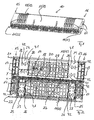
- shows a perspective view of a preferred exemplary embodiment of a cable closure in form of an inline cable closure in a closed status of the same;
- Figure 2
- shows a perspective view of the inline cable closure shown in
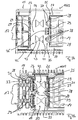
figure 1 in an opened status of the same; - Figure 3a
- shows a detail of a first, upper shell of the inline cable closure;
- Figure 3b
- shows a second view of the detail of
figure 3a ; - Figure 4a
- shows a detail of a second, lower shell of the inline cable closure;
- Figure 4b
- shows a second view of the detail of
figure 4a ; - Figure 5a
- shows a first perspective view of a second segment of a barrier wall used in the first, lower shell of the inline cable closure;
- Figure 5b
- shows a second perspective view of the second segment of the barrier wall of
figure 5a ; - Figure 6a
- shows a first perspective view of a second segment of a barrier wall used in the second, upper shell of the inline cable closure;
- Figure 6b
- shows a second perspective view of the second segment of the barrier wall of
figure 6a ; - Figure 7a
- shows a first perspective view of an alternative second segment of a barrier wall used in the second, upper shell of the inline cable closure;
- Figure 7b
- shows a second perspective view of the second segment of the barrier wall of
figure 7a ; - Figure 8
- shows an alternative of the detail of
figure 3b ; and - Figure 9
- shows another alternative of the detail of
figure 3b . - The present invention relates to a
cable closure 10 preferably for copper cables or fiber optic cables or hybrid cables, which in the preferred exemplary embodiment shown is an inline cable closure. Thecable closure 10 comprises a housing which is formed by a coveringbody 13 composed of twoshells 11 and 12. - In the exemplary embodiment shown, the
shells 11 and 12 are half-shells and the half-shell 11 is a so-called lower half-shell and the half-shell 12 is a so-called upper half-shell of the coveringbody 13, which together define aninterior 14 of theinline cable closure 10.Cable insertion regions 17 are formed on mutuallyopposite sides inline cable closure 10 or the coveringbody 13, with it being possible for cables to be inserted into theinterior 14 of theinline cable closure 10 or passed out of theinterior 14. - In the exemplary embodiment shown, in each case two
cable insertion regions 17 for inserting in each case one cable into theinterior 14 of theinline cable closure 10 are formed on both mutuallyopposite sides body 13. - In the shown embodiment, the two half-
shells 11 and 12 are hinged together at firstlongitudinal sides 18, 19 of the same. The half-shells 11 and 12 can be pivoted with respect to each other around a hinge 20 by which the two half-shells 11 and 12 are fixed to each other at the firstlongitudinal sides 18, 19 of the same. When theinline cable closure 10 is closed, the other secondlongitudinal sides 21, 22 of the two half-shells 11 and 12 can be secured to each other by a closing mechanism such as a latch, a hook, a pin or the like (not shown). - In order to ensure that the cables to be inserted into the
interior 14 of theinline cable closure 10 via thecable insertion regions 17 are sealed off, compressible and/ordeformable sealing elements barrier walls opposite sides body 13 of theinline cable closure 10 on which thecable insertion regions 17 are formed. Thesealing elements 23 are associated with the lower half-shell 11 and thesealing elements 24 are associated with the upper half-shell 12. Afirst barrier wall 25 is in each case, namely on both mutuallyopposite sides shell 11 and in the region of the upper half-shell 12, remote from theinterior 14 of theinline cable closure 10 while asecond barrier wall 26 is in each case facing theinterior 14 of thecable closure 10. - As shown in
Figure 2 , the compressible and/ordeformable sealing elements 24 of the upper half-shell 12, which are associated with thecable insertion regions 17, are coupled via compressible and/ordeformable sealing elements 27, which run parallel to longitudinal sides 18, 21 of the upper half-shell 12. As a result, a closed, preferably rectangular-framed, sealing region is formed by thesealing elements shell 11. - The compressible and/or
deformable sealing elements 24 and possibly 27 are preferably gel-like sealing elements, for example polyurethane gels or silicone gels. Such gel-like sealing elements are deformable and can be compressible. It is also possible to use sealingelements 24 which are partially composed of different materials, for example from a deformable, gel-like sealing material and from a foam-like compressible sealing material. - Each of the
barrier walls shells 11 and 12 comprises afirst segment 28 being fixedly attached to the respective half-shell 11, 12 and at least onesecond segment 29 being a separate component from thefirst segment 28 of therespective barrier wall second segment 29 is separately formed from the respectivefirst segment 28. In other words, the or eachsecond segment 29 is disjoined from the respectivefirst segment 28. Thefirst segment 28 of eachbarrier wall like openings 30 for receiving the respectivesecond segment 29. - The
first segments 28 and thesecond segments 29 of thebarrier walls cable insertion regions 17. Thebarrier walls cable insertion regions 17 confine an angle between 85° and 95°, preferably an angle between 87° and 93°. These ranges are merely provided as examples. - In the region of the lower half-shell 11 a
middle section 31 of thefirst segment 28 of eachbarrier wall second segments 29 is T-shaped having aprotrusion 32 running almost in parallel with respect to the insertion direction of thecable insertion regions 17. - As can be best seen in
Figures 2 ,3a and 4a , in the region of each of the mutuallyopposite sides shells 11, 12 of the coveringbody 13, namely in the region of the lower half-shell 11, the distance x between therespective barrier wall 26 facing the interior 14 of the cable closure and therespective barrier wall 25 remote from theinterior 14 of thecable closure 10 is smaller than the respective distance y between thebarrier walls opposite sides shells 11, 12 of the coveringbody 13, namely in the region of the upper half-shell 12. The distances x and y are preferably dimensioned according to the following relationship: 1,2 ≤ y/x ≤ 1,7, more preferably 1,3 ≤ y/x ≤ 1,6. These ranges are merely provided as examples. - When the covering
body 13 of the housing is closed by bringing the half-shells 11 and 12 in the position shown inFigure 1 , edges 33 of thebarrier walls shell 11 extending almost or in general transversely with respect to the insertion direction of thecable insertion regions 17 contact, namely compress and/or deform, the respective compressible and/ordeformable sealing element 24 positioned between of thebarrier walls barrier walls shell 11 extending almost in parallel or in general in longitudinal direction to the insertion direction of thecable insertion regions 17 contact, namely compress and/or deform, the respective compressible and/ordeformable sealing element 24 positioned between of thebarrier walls edges 34 extending almost in parallel or in longitudinal direction to the insertion direction of thecable insertion regions 17 are provided by theprotrusion 32 of the T-shapedmiddle sections 31 of thefirst segments 28 of thebarrier walls - Thereby the compressible and/or
deformable sealing element 24 becomes compressed and/or deformed so that the respectivecable insertion region 17 is sealed even in the case that no cable is to be handled in the respectivecable insertion region 17. - At least the
barrier walls 26 of the half-shells 11, 12 facing the interior 14 of thecable closure 10 comprise in the region of eachcable insertion region 17spring elements resilient fingers resilient fingers spring elements deformable sealing element respective barrier wall 26 facing the interior 14 of the cable closure and therespective barrier wall 25 remote from theinterior 14 of the cable closure.Figures 5a, 5b show a preferred embodiment ofspring element 35 used in the region of the lower half-shell 11 andfigures 6a, 6b as well asfigures 7a, 7b show preferred embodiments ofspring elements 36, 36' used in the region of the upper half-shell 12.Figures 3b and 4b show thespring element resilient fingers deformable sealing element - The
spring elements resilient fingers deformable sealing element second segment 29 of therespective barrier wall 26. Theresilient fingers fans fans fans - First ends 39 of the
resilient fingers spring elements second segment 29 of therespective barrier wall 26 and opposing free second ends 40 of theresilient fingers spring elements resilient fingers deformable sealing element - The embedded
resilient fingers spring elements deformable sealing element cable closure 10. The embeddedresilient fingers spring elements respective sealing element respective sealing element elements cable closure 10. - The embedded
resilient fingers spring elements cable insertion region 17 confine an angle between 20° and 70°, preferably between 30° and 60°, thereby proving the narrowing cross section of thefans resilient fingers - As shown in
figures 3a and3b , the sealingelements resilient fingers spring elements resilient fingers spring element recesses 41 having a generally narrowing cross section. Therecesses 41 are like thefans - At least in the region of the
barrier walls 26 facing the interior 14 of the cable closure there is such arecess 41 in the region of eachcable insertion region 17 adjacent to the embeddedresilient fingers respective spring element cable closure 10. When sealing a cable, the material of therespective sealing element recesses 41 thereby avoiding a so called "Eye-ball effect". The so called "Eye-ball effect" affects negatively the sealing properties by a bulge of the material of therespective sealing element respective sealing element recesses 41 allow the handling and sealing of cables with different cable diameters. - In addition to the
recesses 41 of the sealingelements resilient fingers spring elements elements cable insertion regions 17additional recesses 42. Each of theadditional recesses 42 has at least three subsections, namely afirst subsection 43 and asecond subsection 44 both having a generally narrowing cross section, preferably both being conically shaped, in such a way that a tapered end of thefirst subsection 43 is facing a tapered end of thesecond subsection 44, and athird subsection 45 preferably being almost cylindrically shaped extending between the tapered end of thefirst subsection 43 and the tapered end of thesecond subsection 44. When sealing a cable, the material of the sealingelements additional recesses 42 thereby further avoiding the so called "Eye-ball effect". - As mentioned above, the so called "Eye-ball effect" affects negatively the sealing properties by a material bulge of the
respective sealing element respective sealing element - The
additional recesses 42 further improve the handling and sealing of cables with different cable diameters. Thethird subsection 45 of theadditional recesses 42 holds a defined sealing pressure on the cable. - By comparing e.g.
figures 5a and6a it can be determined that theresilient fingers 37 or flaps of thespring elements 35 being embedded in the compressible and/ordeformable sealing elements 23 of the lower half-shell 11 have a shorter length than theresilient fingers 38 or flaps of thespring elements 36 being embedded in the compressible and/ordeformable sealing elements 24 of the upper half-shell 12. The lengths of theresilient fingers barrier walls shorter fingers 37 is preferably in the flowing range: 0,1≤I/x≤0,3. The length I of thelonger fingers 38 is preferably in the flowing range: 0,1≤I/y≤0,3. - As shown in
figures 6a, 6b andfigures 7a, 7b , eachbarrier wall 26 of the upper half-shell 12 facing the interior 14 of thecable closure 10, namely the respectivesecond segment 29 of therespective barrier wall 26, comprises between twoadjacent spring elements 36 of the same aprotrusion 46 being embedded in the compressible and/ordeformable sealing element 24 positioned between therespective barrier wall 26 facing the interior 14 of the cable closure and therespective barrier wall 25 remote from theinterior 14 of thecable closure 10. Theprotrusion 46 is formed plate-like or generally flat having a pattern ofopenings 47 extending through the same. - The embedded
protrusions 46 also keep the compressible and/ordeformable sealing element 24 in place during operation or during testing of thecable closure 10. The embeddedprotrusions 46 decrease a radial sliding of therespective sealing element 24 which may be caused by thermal expansion of the compressible and/ordeformable sealing element 24. This further minimizes the risk that the sealingelements 24 become damaged during operation or testing and improves further the sealing properties of thecable closure 10. - In the embodiment shown in
figures 7a, 7b , eachbarrier wall 26 of the upper half-shell 12 facing the interior 14 of the cable closure comprises on each side of each spring element 36' aprotrusion respective sealing element 24 positioned between therespective barrier wall 26 facing the interior 14 of the cable closure and therespective barrier wall 25 remote from theinterior 14 of the cable closure. Theprotrusions openings 47 extending through the same. - The
protrusions 48 and theprotrusion 46 are preferably positioned in a common plane. - Alternatively, the only the
lateral protrusions 48 are positioned in a common plane but in a different plane than themiddle protrusion 46. -
Figure 8 shows a detail similar tofigure 3b , whereby the infigure 3b thespring element 36 offigures 6a, 6b and infigure 8 the spring element 36' offigures 7a, 7b are used in the region of thebarrier walls 26 of the upper half-shell 12 facing the interior 14 of the cable closure. -
Figure 9 shows an embodiment in which also thebarrier walls 25 of the upper half-shell 12 remote the interior 14 of the cable closure comprise in the region of eachcable insertion region 17spring elements 35 withresilient fingers 37 or flaps, whereby theresilient fingers 37 or flaps of thespring elements 35 are embedded in therespective sealing element 24 positioned between therespective barrier wall 26 facing the interior 14 of the cable closure and therespective barrier wall 25 remote from theinterior 14 of the cable closure. In other words, infigure 9 each barrier wall, namely thebarrier walls 26 facing the interior 14 of the cable closure and thebarrier walls 25 remote from theinterior 14 of the cable closure, of the upper-half shell 12 comprises in the region of eachcable insertion region 17spring elements 35, 36' withresilient fingers respective sealing element respective barrier walls - The
resilient fingers 38 or flaps associated with thebarrier walls 26 of the upper half-shell 12 facing the interior 14 of the cable closure have a larger length than theresilient fingers 37 or flaps associated with thebarrier walls 25 of the upper half-shell 12 remote from theinterior 14 of the cable closure. Theresilient fingers 37 or flaps associated with thebarrier walls 25 of the upper half-shell 12 remote from theinterior 14 of the cable closure have the same length like theresilient fingers 37 or flaps associated with thebarrier walls 26 of the lower half-shell 11 facing the interior 14 of the cable closure. - In other words, the
spring elements 35 associated with thebarrier walls 25 of the upper half-shell 12 remote the interior 14 of the cable closure correspond to thespring elements 35 shown infigures 5a, 5b used in the region of the lower half-shell 11. -
- 10
- inline cable closure
- 11
- shell/lower half-shell
- 12
- shell/upper half-shell
- 13
- covering body
- 14
- interior
- 15
- side
- 16
- side
- 17
- cable insertion region
- 18
- longitudinal side
- 19
- longitudinal side
- 20
- hinge
- 21
- longitudinal side
- 22
- longitudinal side
- 23
- sealing element
- 24
- sealing element
- 25
- barrier wall
- 26
- barrier wall
- 27
- sealing element
- 28
- first segment
- 29
- second segment
- 30
- pocket-like opening
- 31
- middle section
- 32
- protrusion
- 33
- edge
- 34
- edge
- 35
- spring element
- 36
- spring element
- 36'
- spring element
- 37
- resilient finger
- 38
- resilient finger
- 39
- first end
- 40
- second end
- 41
- recess
- 42
- additional recess
- 43
- first subsection
- 44
- second subsection
- 45
- third subsection
- 46
- protrusion
- 47
- opening
- 48
- protrusion
- 49
- fan
- 50
- fan
Claims (13)
- A cable closure, having a housing, which delimits an interior of the cable closure and seals off the cable closure toward the outside, the housing comprising a covering body (13), the covering body (13) comprises shells (11, 12) and provides on mutually opposite sides (15, 16) of the same cable insertion regions (17) for inserting cables into the interior of the cable closure and/or for passing cables out of the interior of the cable closure, wherein compressible and/or deformable sealing elements (23, 24) are positioned at the mutually opposite sides (15, 16) of the covering body (13) in the region of the cable insertion regions (17) of the shells (11, 12), wherein each of the sealing elements (23, 24) is positioned between barrier walls (25, 26) of the respective shell (11, 12), namely between a barrier wall (26) facing the interior (14) of the cable closure and a barrier wall (25) remote from the interior (14) of the cable closure, and wherein at least the barrier walls (26) of the shells (11, 12) facing the interior (14) of the cable closure comprise in the region of each cable insertion region (17) spring elements (35, 36, 36') with resilient fingers (37, 38) or flaps, whereby the resilient fingers (37, 38) or flaps of the spring elements (35, 36) are embedded in the respective sealing element (23, 24) positioned between the respective barrier wall (26) facing the interior (14) of the cable closure and the respective barrier wall (25) remote from the interior of the cable closure, characterized in that
in the region of each of the mutually opposite sides (15, 16) of a first one of the shells (11) of the covering body (13) the distance (x) between the respective barrier wall (26) facing the interior (14) of the cable closure and the respective barrier wall (25) remote from the interior (14) of the cable closure is smaller than the respective distance (y) between the barrier walls (25, 26) in the region of each of the mutually opposite sides (15, 16) of a second one of the shells (12) of the covering body (13), and
each barrier wall (26), namely a second segment (29) of the same, of the second one of the shells (12) facing the interior (14) of the cable closure comprises between two adjacent spring elements (36, 36') a protrusion (46) being embedded in the respective sealing element (24) positioned between the respective barrier wall (26) facing the interior (14) of the cable closure and the respective barrier wall (25) remote from the interior (14) of the cable closure. - The cable closure as claimed in claim 1, characterized in that each barrier wall (25, 26) of said shells (11, 12) comprises a first segment (28) being fixedly attached to the respective shell and at least one second segment (29) being a separate component from the respective first segment (28), whereby the spring elements (35, 36, 36') are an integral part of the or each respective second segment (29).
- The cable closure as claimed in claim 1 or 2, characterized in that the sealing elements (23, 24), in which the resilient fingers (37, 38) or flaps of the spring elements (35, 36, 36') are embedded, comprise, at least in the region of the barrier walls (26) facing the interior (14) of the cable closure adjacent to the embedded resilient fingers (37, 38), recesses (41) having a generally narrowing cross section.
- The cable closure as claimed in one of claims 1 to 3, characterized in that each barrier wall (25, 26) of each of the shells (11, 12) extends almost transversely with respect to a cable insertion direction of the respective cable insertion region (17).
- The cable closure as claimed in one of claims 1 to 4, characterized in that the resilient fingers (37, 38) or flaps of the spring elements (35, 36, 36') provide resilient fans (49, 50), whereby the fans (49, 50) have a generally narrowing cross section. spring elements (35, 36, 36') with resilient fingers (37, 38) or flaps being embedded in the respective sealing element (23, 24) positioned between the respective barrier walls (25, 26).
- The cable closure as claimed in claim 10, characterized in that the resilient fingers (38) or flaps associated with the barrier walls (26) of the second one of the shells (12) facing the interior (14) of the cable closure have a larger length than the resilient fingers (37) or flaps associated with the barrier walls (25) of the second one of the shells (12) remote from the interior (14) of the cable closure.
- The cable closure as claimed in claim 10, characterized in that the resilient fingers (37) or flaps associated with the barrier walls (25) of the second one of the shells (12) remote from the interior (14) of the cable closure have the same length like the resilient fingers (37) or flaps associated with the barrier walls (26) of the first one of the shells (11) facing the interior (14) of the cable closure.
- The cable closure as claimed in one of claims 1 to 12, characterized in that edges (33) of the barrier walls (25, 26) of the first one of the shells (11) extending transversely with respect to the insertion direction of the cable insertion regions (17) contact, namely compress and/or deform, the respective sealing element (24) positioned between of the barrier walls (25, 26) of the second one of the shells (12) when the covering body (13) of the housing is closed.
Priority Applications (4)
| Application Number | Priority Date | Filing Date | Title |
|---|---|---|---|
| EP11190438.9A EP2597744B1 (en) | 2011-11-24 | 2011-11-24 | Cable closure |
| BR212014012529-0U BR212014012529Y1 (en) | 2011-11-24 | 2012-11-20 | CABLE CLOSURE |
| PCT/US2012/066024 WO2013078183A2 (en) | 2011-11-24 | 2012-11-20 | Cable closure |
| TW101143725A TW201334338A (en) | 2011-11-24 | 2012-11-22 | Cable closure |
Applications Claiming Priority (1)
| Application Number | Priority Date | Filing Date | Title |
|---|---|---|---|
| EP11190438.9A EP2597744B1 (en) | 2011-11-24 | 2011-11-24 | Cable closure |
Publications (2)
| Publication Number | Publication Date |
|---|---|
| EP2597744A1 EP2597744A1 (en) | 2013-05-29 |
| EP2597744B1 true EP2597744B1 (en) | 2015-01-07 |
Family
ID=47258130
Family Applications (1)
| Application Number | Title | Priority Date | Filing Date |
|---|---|---|---|
| EP11190438.9A Active EP2597744B1 (en) | 2011-11-24 | 2011-11-24 | Cable closure |
Country Status (4)
| Country | Link |
|---|---|
| EP (1) | EP2597744B1 (en) |
| BR (1) | BR212014012529Y1 (en) |
| TW (1) | TW201334338A (en) |
| WO (1) | WO2013078183A2 (en) |
Cited By (4)
| Publication number | Priority date | Publication date | Assignee | Title |
|---|---|---|---|---|
| US10996414B1 (en) | 2020-03-23 | 2021-05-04 | Afl Telecommunications Llc | Butt closures and bases therefor |
| USD960116S1 (en) | 2016-04-07 | 2022-08-09 | Corning Optical Communications LLC | Telecommunications closure with surface ornamentation |
| US11561354B2 (en) | 2018-05-09 | 2023-01-24 | Afl Telecommunications Llc | Butt closures and bases therefor |
| US12078846B2 (en) | 2020-11-30 | 2024-09-03 | Afl Telecommunications Llc | Butt closures and bases therefor |
Families Citing this family (1)
| Publication number | Priority date | Publication date | Assignee | Title |
|---|---|---|---|---|
| WO2015115367A1 (en) | 2014-01-30 | 2015-08-06 | 日立オートモティブシステムズ株式会社 | Mechanical quantity measuring device and sensor unit |
Family Cites Families (4)
| Publication number | Priority date | Publication date | Assignee | Title |
|---|---|---|---|---|
| JP4044668B2 (en) * | 1998-03-09 | 2008-02-06 | 株式会社ジャパンリーコム | End face seal member in cable wiring closure |
| BR9910571A (en) * | 1998-04-28 | 2001-01-16 | Tyco Electronics Raychem Nv | Wrap |
| US7214735B2 (en) * | 2004-02-02 | 2007-05-08 | 3M Innovative Properties Company | Microsphere-filled sealant materials |
| DE202010006582U1 (en) | 2010-05-07 | 2010-08-05 | CCS Technology, Inc., Wilmington | Inline cable sleeve |
-
2011
- 2011-11-24 EP EP11190438.9A patent/EP2597744B1/en active Active
-
2012
- 2012-11-20 BR BR212014012529-0U patent/BR212014012529Y1/en not_active IP Right Cessation
- 2012-11-20 WO PCT/US2012/066024 patent/WO2013078183A2/en active Application Filing
- 2012-11-22 TW TW101143725A patent/TW201334338A/en unknown
Cited By (5)
| Publication number | Priority date | Publication date | Assignee | Title |
|---|---|---|---|---|
| USD960116S1 (en) | 2016-04-07 | 2022-08-09 | Corning Optical Communications LLC | Telecommunications closure with surface ornamentation |
| US11561354B2 (en) | 2018-05-09 | 2023-01-24 | Afl Telecommunications Llc | Butt closures and bases therefor |
| US10996414B1 (en) | 2020-03-23 | 2021-05-04 | Afl Telecommunications Llc | Butt closures and bases therefor |
| US11500170B2 (en) | 2020-03-23 | 2022-11-15 | Afl Telecommunications Llc | Butt closures and bases therefor |
| US12078846B2 (en) | 2020-11-30 | 2024-09-03 | Afl Telecommunications Llc | Butt closures and bases therefor |
Also Published As
| Publication number | Publication date |
|---|---|
| BR212014012529U2 (en) | 2015-11-10 |
| EP2597744A1 (en) | 2013-05-29 |
| WO2013078183A3 (en) | 2014-04-17 |
| WO2013078183A2 (en) | 2013-05-30 |
| BR212014012529Y1 (en) | 2019-10-08 |
| TW201334338A (en) | 2013-08-16 |
Similar Documents
| Publication | Publication Date | Title |
|---|---|---|
| EP2597744B1 (en) | Cable closure | |
| EP2520959B1 (en) | Cable strain relief device for cable closures and cable closure having at least one such cable strain relief device | |
| US9012774B2 (en) | Sealing member for an enclosure | |
| KR100684024B1 (en) | Cable closure and method of enclosing a cable | |
| KR20010074636A (en) | A seal | |
| AU7502294A (en) | Sealing member | |
| EP2520960B1 (en) | Cable closure | |
| EP2557443B1 (en) | Cable enclosure | |
| EP2521230B1 (en) | Cable closure | |
| EP2557442B1 (en) | Cable closure | |
| US9337561B2 (en) | Contact element for a plug type connector and arrangement comprising a contact element | |
| EP2808966B1 (en) | Cable closure | |
| EP2665148A1 (en) | Cable closure | |
| JP7178461B2 (en) | Angled housing parts and angled housing assemblies | |
| JPH09502858A (en) | Closure device for cable connection | |
| US20140050452A1 (en) | Cable closure | |
| TW201304336A (en) | Cable strain relief device for cable closures and cable closure having at least one such cable strain relief device |
Legal Events
| Date | Code | Title | Description |
|---|---|---|---|
| PUAI | Public reference made under article 153(3) epc to a published international application that has entered the european phase |
Free format text: ORIGINAL CODE: 0009012 |
|
| AK | Designated contracting states |
Kind code of ref document: A1 Designated state(s): AL AT BE BG CH CY CZ DE DK EE ES FI FR GB GR HR HU IE IS IT LI LT LU LV MC MK MT NL NO PL PT RO RS SE SI SK SM TR |
|
| AX | Request for extension of the european patent |
Extension state: BA ME |
|
| 17P | Request for examination filed |
Effective date: 20131127 |
|
| RBV | Designated contracting states (corrected) |
Designated state(s): AL AT BE BG CH CY CZ DE DK EE ES FI FR GB GR HR HU IE IS IT LI LT LU LV MC MK MT NL NO PL PT RO RS SE SI SK SM TR |
|
| GRAJ | Information related to disapproval of communication of intention to grant by the applicant or resumption of examination proceedings by the epo deleted |
Free format text: ORIGINAL CODE: EPIDOSDIGR1 |
|
| GRAP | Despatch of communication of intention to grant a patent |
Free format text: ORIGINAL CODE: EPIDOSNIGR1 |
|
| INTG | Intention to grant announced |
Effective date: 20140623 |
|
| GRAS | Grant fee paid |
Free format text: ORIGINAL CODE: EPIDOSNIGR3 |
|
| GRAP | Despatch of communication of intention to grant a patent |
Free format text: ORIGINAL CODE: EPIDOSNIGR1 |
|
| GRAA | (expected) grant |
Free format text: ORIGINAL CODE: 0009210 |
|
| INTG | Intention to grant announced |
Effective date: 20141120 |
|
| AK | Designated contracting states |
Kind code of ref document: B1 Designated state(s): AL AT BE BG CH CY CZ DE DK EE ES FI FR GB GR HR HU IE IS IT LI LT LU LV MC MK MT NL NO PL PT RO RS SE SI SK SM TR |
|
| REG | Reference to a national code |
Ref country code: GB Ref legal event code: FG4D |
|
| REG | Reference to a national code |
Ref country code: CH Ref legal event code: EP |
|
| REG | Reference to a national code |
Ref country code: IE Ref legal event code: FG4D |
|
| REG | Reference to a national code |
Ref country code: AT Ref legal event code: REF Ref document number: 706315 Country of ref document: AT Kind code of ref document: T Effective date: 20150215 |
|
| REG | Reference to a national code |
Ref country code: DE Ref legal event code: R096 Ref document number: 602011012849 Country of ref document: DE Effective date: 20150226 |
|
| REG | Reference to a national code |
Ref country code: NL Ref legal event code: VDEP Effective date: 20150107 |
|
| REG | Reference to a national code |
Ref country code: AT Ref legal event code: MK05 Ref document number: 706315 Country of ref document: AT Kind code of ref document: T Effective date: 20150107 |
|
| REG | Reference to a national code |
Ref country code: LT Ref legal event code: MG4D |
|
| PG25 | Lapsed in a contracting state [announced via postgrant information from national office to epo] |
Ref country code: FI Free format text: LAPSE BECAUSE OF FAILURE TO SUBMIT A TRANSLATION OF THE DESCRIPTION OR TO PAY THE FEE WITHIN THE PRESCRIBED TIME-LIMIT Effective date: 20150107 Ref country code: SE Free format text: LAPSE BECAUSE OF FAILURE TO SUBMIT A TRANSLATION OF THE DESCRIPTION OR TO PAY THE FEE WITHIN THE PRESCRIBED TIME-LIMIT Effective date: 20150107 Ref country code: NO Free format text: LAPSE BECAUSE OF FAILURE TO SUBMIT A TRANSLATION OF THE DESCRIPTION OR TO PAY THE FEE WITHIN THE PRESCRIBED TIME-LIMIT Effective date: 20150407 Ref country code: LT Free format text: LAPSE BECAUSE OF FAILURE TO SUBMIT A TRANSLATION OF THE DESCRIPTION OR TO PAY THE FEE WITHIN THE PRESCRIBED TIME-LIMIT Effective date: 20150107 Ref country code: HR Free format text: LAPSE BECAUSE OF FAILURE TO SUBMIT A TRANSLATION OF THE DESCRIPTION OR TO PAY THE FEE WITHIN THE PRESCRIBED TIME-LIMIT Effective date: 20150107 Ref country code: BG Free format text: LAPSE BECAUSE OF FAILURE TO SUBMIT A TRANSLATION OF THE DESCRIPTION OR TO PAY THE FEE WITHIN THE PRESCRIBED TIME-LIMIT Effective date: 20150407 Ref country code: ES Free format text: LAPSE BECAUSE OF FAILURE TO SUBMIT A TRANSLATION OF THE DESCRIPTION OR TO PAY THE FEE WITHIN THE PRESCRIBED TIME-LIMIT Effective date: 20150107 |
|
| PG25 | Lapsed in a contracting state [announced via postgrant information from national office to epo] |
Ref country code: RS Free format text: LAPSE BECAUSE OF FAILURE TO SUBMIT A TRANSLATION OF THE DESCRIPTION OR TO PAY THE FEE WITHIN THE PRESCRIBED TIME-LIMIT Effective date: 20150107 Ref country code: PL Free format text: LAPSE BECAUSE OF FAILURE TO SUBMIT A TRANSLATION OF THE DESCRIPTION OR TO PAY THE FEE WITHIN THE PRESCRIBED TIME-LIMIT Effective date: 20150107 Ref country code: AT Free format text: LAPSE BECAUSE OF FAILURE TO SUBMIT A TRANSLATION OF THE DESCRIPTION OR TO PAY THE FEE WITHIN THE PRESCRIBED TIME-LIMIT Effective date: 20150107 Ref country code: GR Free format text: LAPSE BECAUSE OF FAILURE TO SUBMIT A TRANSLATION OF THE DESCRIPTION OR TO PAY THE FEE WITHIN THE PRESCRIBED TIME-LIMIT Effective date: 20150408 Ref country code: NL Free format text: LAPSE BECAUSE OF FAILURE TO SUBMIT A TRANSLATION OF THE DESCRIPTION OR TO PAY THE FEE WITHIN THE PRESCRIBED TIME-LIMIT Effective date: 20150107 Ref country code: IS Free format text: LAPSE BECAUSE OF FAILURE TO SUBMIT A TRANSLATION OF THE DESCRIPTION OR TO PAY THE FEE WITHIN THE PRESCRIBED TIME-LIMIT Effective date: 20150507 Ref country code: LV Free format text: LAPSE BECAUSE OF FAILURE TO SUBMIT A TRANSLATION OF THE DESCRIPTION OR TO PAY THE FEE WITHIN THE PRESCRIBED TIME-LIMIT Effective date: 20150107 |
|
| REG | Reference to a national code |
Ref country code: DE Ref legal event code: R097 Ref document number: 602011012849 Country of ref document: DE |
|
| PG25 | Lapsed in a contracting state [announced via postgrant information from national office to epo] |
Ref country code: SK Free format text: LAPSE BECAUSE OF FAILURE TO SUBMIT A TRANSLATION OF THE DESCRIPTION OR TO PAY THE FEE WITHIN THE PRESCRIBED TIME-LIMIT Effective date: 20150107 Ref country code: EE Free format text: LAPSE BECAUSE OF FAILURE TO SUBMIT A TRANSLATION OF THE DESCRIPTION OR TO PAY THE FEE WITHIN THE PRESCRIBED TIME-LIMIT Effective date: 20150107 Ref country code: DK Free format text: LAPSE BECAUSE OF FAILURE TO SUBMIT A TRANSLATION OF THE DESCRIPTION OR TO PAY THE FEE WITHIN THE PRESCRIBED TIME-LIMIT Effective date: 20150107 Ref country code: CZ Free format text: LAPSE BECAUSE OF FAILURE TO SUBMIT A TRANSLATION OF THE DESCRIPTION OR TO PAY THE FEE WITHIN THE PRESCRIBED TIME-LIMIT Effective date: 20150107 Ref country code: RO Free format text: LAPSE BECAUSE OF FAILURE TO SUBMIT A TRANSLATION OF THE DESCRIPTION OR TO PAY THE FEE WITHIN THE PRESCRIBED TIME-LIMIT Effective date: 20150107 |
|
| PLBE | No opposition filed within time limit |
Free format text: ORIGINAL CODE: 0009261 |
|
| STAA | Information on the status of an ep patent application or granted ep patent |
Free format text: STATUS: NO OPPOSITION FILED WITHIN TIME LIMIT |
|
| REG | Reference to a national code |
Ref country code: FR Ref legal event code: PLFP Year of fee payment: 5 |
|
| 26N | No opposition filed |
Effective date: 20151008 |
|
| PG25 | Lapsed in a contracting state [announced via postgrant information from national office to epo] |
Ref country code: IT Free format text: LAPSE BECAUSE OF FAILURE TO SUBMIT A TRANSLATION OF THE DESCRIPTION OR TO PAY THE FEE WITHIN THE PRESCRIBED TIME-LIMIT Effective date: 20150107 |
|
| PG25 | Lapsed in a contracting state [announced via postgrant information from national office to epo] |
Ref country code: SI Free format text: LAPSE BECAUSE OF FAILURE TO SUBMIT A TRANSLATION OF THE DESCRIPTION OR TO PAY THE FEE WITHIN THE PRESCRIBED TIME-LIMIT Effective date: 20150107 |
|
| PG25 | Lapsed in a contracting state [announced via postgrant information from national office to epo] |
Ref country code: BE Free format text: LAPSE BECAUSE OF FAILURE TO SUBMIT A TRANSLATION OF THE DESCRIPTION OR TO PAY THE FEE WITHIN THE PRESCRIBED TIME-LIMIT Effective date: 20150107 |
|
| PG25 | Lapsed in a contracting state [announced via postgrant information from national office to epo] |
Ref country code: MC Free format text: LAPSE BECAUSE OF FAILURE TO SUBMIT A TRANSLATION OF THE DESCRIPTION OR TO PAY THE FEE WITHIN THE PRESCRIBED TIME-LIMIT Effective date: 20150107 Ref country code: LU Free format text: LAPSE BECAUSE OF FAILURE TO SUBMIT A TRANSLATION OF THE DESCRIPTION OR TO PAY THE FEE WITHIN THE PRESCRIBED TIME-LIMIT Effective date: 20151124 |
|
| REG | Reference to a national code |
Ref country code: CH Ref legal event code: PL |
|
| PG25 | Lapsed in a contracting state [announced via postgrant information from national office to epo] |
Ref country code: LI Free format text: LAPSE BECAUSE OF NON-PAYMENT OF DUE FEES Effective date: 20151130 Ref country code: CH Free format text: LAPSE BECAUSE OF NON-PAYMENT OF DUE FEES Effective date: 20151130 |
|
| REG | Reference to a national code |
Ref country code: IE Ref legal event code: MM4A |
|
| PG25 | Lapsed in a contracting state [announced via postgrant information from national office to epo] |
Ref country code: IE Free format text: LAPSE BECAUSE OF NON-PAYMENT OF DUE FEES Effective date: 20151124 |
|
| REG | Reference to a national code |
Ref country code: FR Ref legal event code: PLFP Year of fee payment: 6 |
|
| PG25 | Lapsed in a contracting state [announced via postgrant information from national office to epo] |
Ref country code: SM Free format text: LAPSE BECAUSE OF FAILURE TO SUBMIT A TRANSLATION OF THE DESCRIPTION OR TO PAY THE FEE WITHIN THE PRESCRIBED TIME-LIMIT Effective date: 20150107 Ref country code: HU Free format text: LAPSE BECAUSE OF FAILURE TO SUBMIT A TRANSLATION OF THE DESCRIPTION OR TO PAY THE FEE WITHIN THE PRESCRIBED TIME-LIMIT; INVALID AB INITIO Effective date: 20111124 |
|
| PG25 | Lapsed in a contracting state [announced via postgrant information from national office to epo] |
Ref country code: CY Free format text: LAPSE BECAUSE OF FAILURE TO SUBMIT A TRANSLATION OF THE DESCRIPTION OR TO PAY THE FEE WITHIN THE PRESCRIBED TIME-LIMIT Effective date: 20150107 |
|
| PG25 | Lapsed in a contracting state [announced via postgrant information from national office to epo] |
Ref country code: MT Free format text: LAPSE BECAUSE OF FAILURE TO SUBMIT A TRANSLATION OF THE DESCRIPTION OR TO PAY THE FEE WITHIN THE PRESCRIBED TIME-LIMIT Effective date: 20150107 |
|
| REG | Reference to a national code |
Ref country code: FR Ref legal event code: PLFP Year of fee payment: 7 |
|
| PG25 | Lapsed in a contracting state [announced via postgrant information from national office to epo] |
Ref country code: TR Free format text: LAPSE BECAUSE OF FAILURE TO SUBMIT A TRANSLATION OF THE DESCRIPTION OR TO PAY THE FEE WITHIN THE PRESCRIBED TIME-LIMIT Effective date: 20150107 Ref country code: PT Free format text: LAPSE BECAUSE OF FAILURE TO SUBMIT A TRANSLATION OF THE DESCRIPTION OR TO PAY THE FEE WITHIN THE PRESCRIBED TIME-LIMIT Effective date: 20150107 Ref country code: MK Free format text: LAPSE BECAUSE OF FAILURE TO SUBMIT A TRANSLATION OF THE DESCRIPTION OR TO PAY THE FEE WITHIN THE PRESCRIBED TIME-LIMIT Effective date: 20150107 |
|
| REG | Reference to a national code |
Ref country code: FR Ref legal event code: PLFP Year of fee payment: 8 |
|
| PG25 | Lapsed in a contracting state [announced via postgrant information from national office to epo] |
Ref country code: AL Free format text: LAPSE BECAUSE OF FAILURE TO SUBMIT A TRANSLATION OF THE DESCRIPTION OR TO PAY THE FEE WITHIN THE PRESCRIBED TIME-LIMIT Effective date: 20150107 |
|
| PGFP | Annual fee paid to national office [announced via postgrant information from national office to epo] |
Ref country code: GB Payment date: 20231013 Year of fee payment: 13 |
|
| PGFP | Annual fee paid to national office [announced via postgrant information from national office to epo] |
Ref country code: FR Payment date: 20231010 Year of fee payment: 13 Ref country code: DE Payment date: 20231010 Year of fee payment: 13 |