EP2597724B1 - Tragbare Kommunikationsvorrichtung - Google Patents
Tragbare Kommunikationsvorrichtung Download PDFInfo
- Publication number
- EP2597724B1 EP2597724B1 EP20120161951 EP12161951A EP2597724B1 EP 2597724 B1 EP2597724 B1 EP 2597724B1 EP 20120161951 EP20120161951 EP 20120161951 EP 12161951 A EP12161951 A EP 12161951A EP 2597724 B1 EP2597724 B1 EP 2597724B1
- Authority
- EP
- European Patent Office
- Prior art keywords
- metal element
- communication device
- portable communication
- antenna
- resonant
- Prior art date
- Legal status (The legal status is an assumption and is not a legal conclusion. Google has not performed a legal analysis and makes no representation as to the accuracy of the status listed.)
- Active
Links
Images



Classifications
-
- H—ELECTRICITY
- H01—ELECTRIC ELEMENTS
- H01Q—ANTENNAS, i.e. RADIO AERIALS
- H01Q1/00—Details of, or arrangements associated with, antennas
- H01Q1/12—Supports; Mounting means
- H01Q1/22—Supports; Mounting means by structural association with other equipment or articles
- H01Q1/24—Supports; Mounting means by structural association with other equipment or articles with receiving set
- H01Q1/241—Supports; Mounting means by structural association with other equipment or articles with receiving set used in mobile communications, e.g. GSM
- H01Q1/242—Supports; Mounting means by structural association with other equipment or articles with receiving set used in mobile communications, e.g. GSM specially adapted for hand-held use
- H01Q1/243—Supports; Mounting means by structural association with other equipment or articles with receiving set used in mobile communications, e.g. GSM specially adapted for hand-held use with built-in antennas
-
- H—ELECTRICITY
- H01—ELECTRIC ELEMENTS
- H01Q—ANTENNAS, i.e. RADIO AERIALS
- H01Q1/00—Details of, or arrangements associated with, antennas
- H01Q1/12—Supports; Mounting means
- H01Q1/22—Supports; Mounting means by structural association with other equipment or articles
- H01Q1/2258—Supports; Mounting means by structural association with other equipment or articles used with computer equipment
- H01Q1/2266—Supports; Mounting means by structural association with other equipment or articles used with computer equipment disposed inside the computer
-
- H—ELECTRICITY
- H01—ELECTRIC ELEMENTS
- H01Q—ANTENNAS, i.e. RADIO AERIALS
- H01Q1/00—Details of, or arrangements associated with, antennas
- H01Q1/48—Earthing means; Earth screens; Counterpoises
-
- H—ELECTRICITY
- H01—ELECTRIC ELEMENTS
- H01Q—ANTENNAS, i.e. RADIO AERIALS
- H01Q1/00—Details of, or arrangements associated with, antennas
- H01Q1/52—Means for reducing coupling between antennas; Means for reducing coupling between an antenna and another structure
-
- H—ELECTRICITY
- H01—ELECTRIC ELEMENTS
- H01Q—ANTENNAS, i.e. RADIO AERIALS
- H01Q3/00—Arrangements for changing or varying the orientation or the shape of the directional pattern of the waves radiated from an antenna or antenna system
- H01Q3/24—Arrangements for changing or varying the orientation or the shape of the directional pattern of the waves radiated from an antenna or antenna system varying the orientation by switching energy from one active radiating element to another, e.g. for beam switching
-
- H—ELECTRICITY
- H01—ELECTRIC ELEMENTS
- H01Q—ANTENNAS, i.e. RADIO AERIALS
- H01Q9/00—Electrically-short antennas having dimensions not more than twice the operating wavelength and consisting of conductive active radiating elements
- H01Q9/04—Resonant antennas
- H01Q9/0407—Substantially flat resonant element parallel to ground plane, e.g. patch antenna
- H01Q9/0421—Substantially flat resonant element parallel to ground plane, e.g. patch antenna with a shorting wall or a shorting pin at one end of the element
-
- H—ELECTRICITY
- H01—ELECTRIC ELEMENTS
- H01Q—ANTENNAS, i.e. RADIO AERIALS
- H01Q9/00—Electrically-short antennas having dimensions not more than twice the operating wavelength and consisting of conductive active radiating elements
- H01Q9/04—Resonant antennas
- H01Q9/06—Details
- H01Q9/14—Length of element or elements adjustable
- H01Q9/145—Length of element or elements adjustable by varying the electrical length
-
- H—ELECTRICITY
- H01—ELECTRIC ELEMENTS
- H01Q—ANTENNAS, i.e. RADIO AERIALS
- H01Q9/00—Electrically-short antennas having dimensions not more than twice the operating wavelength and consisting of conductive active radiating elements
- H01Q9/04—Resonant antennas
- H01Q9/30—Resonant antennas with feed to end of elongated active element, e.g. unipole
- H01Q9/42—Resonant antennas with feed to end of elongated active element, e.g. unipole with folded element, the folded parts being spaced apart a small fraction of the operating wavelength
-
- H—ELECTRICITY
- H04—ELECTRIC COMMUNICATION TECHNIQUE
- H04M—TELEPHONIC COMMUNICATION
- H04M1/00—Substation equipment, e.g. for use by subscribers
- H04M1/02—Constructional features of telephone sets
- H04M1/0202—Portable telephone sets, e.g. cordless phones, mobile phones or bar type handsets
- H04M1/026—Details of the structure or mounting of specific components
Definitions
- the subject application relates to a communication device. More particularly, the subject application relates to a portable communication device.
- portable communication devices such as mobile phones, personal digital assistants (PDAs) and tablets, have become very popular and are considered indispensable for many people.
- Antennas configured to radiate and receive electromagnetic waves so as to transmit and exchange wireless information signals are undoubtedly one of the most important components of portable communication devices.
- the antenna must be designed to work with multiple frequency bands, so as to encompass a plurality of operating frequency bands used by such systems.
- portable communication devices are becoming increasingly thinner, lighter and miniaturized, physical limits are placed on the antennas used in portable communication devices. As a result, the design of such multi-band antennas is made ever more difficult.
- a bezel of the portable communication device is cut into a plurality of metal segments, and through implementation of various structural designs, these segments serve as portions of the antenna of the portable communication device.
- the parasitic capacitance effect on the cut-out portions of the bezel cause resonant frequency shift and an increase in the return loss of an antenna resonant mode when a user's hand is close to or touches these cut-out portions of the bezel. This may cause communication interruption or poor reception in the portable communication device.
- the subject application is directed to a portable communication device as defined in claim 1.
- the portable communication device includes an appearance, a substrate and a switchable resonant antenna.
- the substrate is disposed in the appearance, and the substrate has a ground plane.
- the switchable resonant antenna comprises a first connection portion, a switching unit, a first metal element and a second metal element, where the first connection portion is electrically coupled between the ground plane and the switching unit, the switching unit is configured to electrically couple the first connection portion to the first metal element or the second metal element according to a control signal generated corresponding to a detected result, in order to generate a first resonant mode.
- the first metal element and the second metal element are portions of the appearance.
- a first resonant cavity is formed between the first metal element and the ground plane when the first connection portion is electronically coupled to the first metal element
- a second resonant cavity is formed between the second metal element and the ground plane when the first connection portion is electronically coupled to the second metal element
- the appearance can include a bezel.
- a first gap is formed between one end of the bezel and the first metal element, and a second gap is formed between another end of the bezel and the second metal element.
- the bezel comprises metal or non-metal.
- the first gap and an electronic length of the first metal element are adjustable for controlling the first resonant mode generated by the first resonant cavity
- the second gap and an electronic length of the second metal element are adjustable for controlling the first resonant mode generated by the second resonant cavity.
- an effective electronic length of the first metal element is equal to an effective electronic length of the second metal element.
- the foregoing portable communication device further includes a first sensing unit and a second sensing unit.
- the first sensing unit is disposed adjacent to the first gap for sensing whether an object is close to or touches the first metal element and accordingly generating a first sensing signal.
- the second sensing unit disposed adjacent to the second gap for sensing whether the object is close to or touches the second metal element and accordingly generating a second sensing signal.
- the foregoing portable communication device further includes a control unit.
- the control unit is electronically coupled to the first sensing unit, the second sensing unit and the switching unit for generating the control signal based on the sensing signals to control a switching state of the switching unit.
- the foregoing portable communication device further includes a planar inverted-F antenna (PIFA).
- the PIFA includes a feeding portion, a ground end, a second connection portion, a first radiating portion and a second radiating portion.
- the feeding portion and the ground end are electronically coupled to the substrate, the ground end is electronically coupled to the ground plane of the substrate, and the second connection portion is electronically coupled to the feeding portion, the ground end, the first radiating portion and the second radiating portion.
- the appearance includes a housing.
- the first radiating portion is disposed on or inside the housing to generate a second resonant mode
- the second radiation portion is also disposed on or inside the housing to generate a third resonant mode.
- the foregoing portable communication device further includes at least one of a monopole antenna, a loop antenna, a slot antenna and an inverted-F antenna to generate resonant modes of required operating frequency bands.
- the parasitic capacitance effect on the resonant frequency and the return loss of the antenna resonant mode can be reduced when a user is close to or touches the portable communication device. Therefore, the communication quality of the portable communication device can be maintained at a high level.
- Fig. 1A is a schematic rear view of a portable communication device 100 according to one embodiment of the present invention. This drawing is used to explain the deployment of the related components of the portable communication device 100 in a rear view, in which the rear view refers to the view opposite to a touch display module (not shown).
- the portable communication device 100 can include an appearance or structure (group of elements and/or components) comprising housing 110, a substrate 120 and a switchable resonant antenna 130.
- the substrate 120 is disposed inside the housing 110 and has a ground plane 122.
- the switchable resonant antenna 130 can include a first connection portion 132, a switching unit 134, a first metal element 136 and a second metal element 138.
- the first connection portion 132 is electrically coupled between the ground plane 122 and the switching unit 134, and the switching unit 134 is configured to electrically couple the first connection portion 132 to the first metal element 136 or the second metal 138 according to a control signal generated corresponding to a detected result, so as to generate a first resonant mode (or a first high frequency mode).
- the resonant frequency (or the operating frequency band) of the first resonant mode can be within the operating frequency band of UMTS-2100, namely 1920 MHz ⁇ 2170 MHz.
- the first metal element 136 and the second metal element 138 are arranged on the housing 110.
- the housing 110 is a structure for accommodating the related components of the portable communication device 100 and the housing 110 includes a frame or a bezel of the portable communication device 100. It is noted that the first metal element 136 and the second metal element 138 can be disposed outside or inside the housing 110, depending on the exterior design requirements of the portable communication device 100, and the present invention is not limited to the embodiment disclosed above.
- the housing 110 can include a bezel 112.
- a first gap G1 is formed between one end of the bezel 112 and the first metal element 136
- a second gap G2 is formed between another end of the bezel 112 and the second metal element 138.
- the bezel 112 can be formed of or comprise metal or non-metal, and both of the structure and the installation of the bezel 112 are determined based on the exterior design requirements of the portable communication device 100, and the present invention is not limited to the foregoing embodiment.
- each of the housing 110, bezel 112, the first metal element 136 and the second metal element 138 can be regarded as a portion of the appearance of the portable communication device 100.
- a first resonant cavity is formed between the first metal element 136 and the ground plane 122 when the first connection portion 132 is electrically coupled to the first metal element 136.
- a second resonant cavity is formed between the second metal element 138 and the ground plane 122 when the first connection portion 132 is electrically coupled to the second metal element 138.
- both the first resonant cavity and the second resonant cavity can be used to generate the first resonant mode, so as to radiate and receive related radio frequency (RF) signals and provide better return loss within the operating frequency band (or the resonant frequency) of the first resonant mode.
- RF radio frequency
- the electrical length (i.e., the resonant path) of the first metal element 136 and the length of the first gap G1 are adjustable for controlling the first resonant mode generated by the first resonant cavity.
- the resonant frequency of the first resonant mode can be controlled within the operating frequency band of UMTS-2100, namely 1920 MHz - 2170 MHz, and provide a better return loss in this frequency band, such as a return loss less than -10dB.
- the electrical length of the second metal element 138 and the length of the second gap G2 are adjustable for controlling the first resonant mode generated by the second resonant chamber.
- the effective electronic length of the first metal element 136 is substantially equal to the effective electronic length of the second metal element 138.
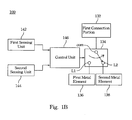
- Fig. 1B is a block diagram of the portable communication device 100 according to one embodiment of the present invention.
- the portable communication device 100 can further include a first sensing unit 142 and a second sensing unit 144.
- the first sensing unit 142 is disposed adjacent to the first gap G1 for sensing whether an object is close to or touches the first metal element 136 and accordingly outputs a first sensing signal.
- the second sensing unit 144 is disposed adjacent to the second gap G2 for sensing whether an object is close to or touches the second metal element 138 and accordingly outputs a second sensing signal.
- the first sensing unit 142 and the second sensing unit 144 can be sensors, such as optic sensors, proximity sensors, pressure sensors, touch sensors, etc.
- the portable communication device 100 can further include a processor (not shown) and a control unit 146.
- the processor can receive the sensing signals of the first sensing unit 142 and the second sensing unit 144, and transmit the processed sensing signals to the control unit 146.
- the processor is not included in the configuration of the portable communication device 100, in which case the control unit 146 is electronically coupled directly to the first sensing unit 142 and the second sensing unit 144, as well as to the switching unit 134.
- the control unit 146 generates signals based on the received sensing signals to control switching states of the switching unit 134.
- the second sensing unit 144 which may be a proximity sensor, senses the object and outputs the second sensing signal to the control unit 146.
- the control unit 146 generates a corresponding control signal based on the second sensing signal, and transmits the control signal to the switching unit 134.
- the switching unit 134 operates in a first switching mode, such that a common end (COM) of the switching unit 134 is connected to a first switching end L1.
- COM common end
- the first connection portion 132 can be electrically coupled to the first metal element 136, and the first resonant cavity is formed between the first metal element 136 and the ground plane 122.
- the first sensing unit 142 senses the object and outputs the first sensing signal to the control unit 146.
- the control unit 146 generates a corresponding control signal based on the first sensing signal and transmits the control signal to the switching unit 134.
- the switching unit 134 operates in a second switching mode, such that the common end (COM) of the switching unit 134 is connected to a second switching end L2.
- the first connection portion 132 can be electrically coupled to the second metal element 138, and the second resonant cavity is formed between the second metal element 138 and the ground plane 122.
- the control unit 146 when the radiation efficiency of the first metal element 136 or of the second metal element 138 is reduced as a result of the user's hand touching or being close to the first metal element 136 or the second metal element 138, the control unit 146 generates a corresponding control signal based on the sensing result.
- the common end (COM) of the switching unit 134 is electrically coupled to the first switch end L1 or the second switching end L2, such that the quality of radiating and receiving electromagnetic waves of the antenna can be maintained at a high level.
- the portable communication device 100 can further include a planar inverted-F antenna (PIFA) 150, in which the PIFA 150 is disposed on an antenna carrier (not shown) or the housing 110.
- the PIFA 150 can include a feeding portion 151, a ground end 152, a second connection portion 154, a first radiating portion 156 and a second radiating portion 158.
- the feeding portion 151 and the ground end 152 can be electrically coupled to the substrate 120 through springs or pogo pins.
- the ground end 152 can be electrically coupled to the ground plane 122 of the substrate 120.
- the springs and the pogo pins can be disposed on the substrate 120.
- the second connection portion 154 is electrically coupled to the feeding portion 151, the ground end 152, the first radiating portion 156 and the second radiating portion 158.
- the appearance can include a housing 110, in which the first radiating portion 156 and the second radiating 158 can be disposed on or inside the housing. It is noted that the plane on which the PIFA 150 is disposed is different from the plane on which the substrate 120 disposed, and the electrical length (or the resonant path) of the first radiating portion 156 and the second radiating portion 158 are different to respectively generate a second resonant mode and a third resonant mode, so as to radiate and receive related RF signals.
- the resonant frequency of the second resonant mode (or the second high frequency mode) generated by the first radiating portion 156 is higher than the resonant frequency of the third resonant mode (or the first low frequency mode) generated by the second radiating portion 158, in which the resonant frequency of the second resonant mode, also called as the second high frequency mode, can be within the operating frequency bands of DCS-1800 and PCS-1900, namely 1710 MHz - 1990 MHz and 1850MHz - 1990MHz, and the resonant frequency of the third resonant mode, also called as the first low frequency mode, can be within the operating frequency band of GSM-900, namely 824 MHz ⁇ 960 MHz.
- the RF signals of the portable communication device 100 can be fed into the second connection portion 154 via the feeding portion 151 of the PIFA 150, and further fed into the first metal element 136 or the second metal element 138 by the coupling effect between the second connection portion 154 and the first connection portion 132, so as to generate the first resonant mode.
- the portable communication device 100 can further include at least one of a monopole antenna, a ring antenna, a slot antenna and an inverted-F antenna for generating resonant modes of required operating frequency bands, so that the portable communication device 100 has a multi-band communication function. It is noted that the type and disposition of the antenna deployed on the portable communication device 100 are not limited to the foregoing embodiment.
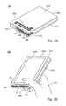
- Fig. 2A is a perspective view of a portable communication device 200 according to one embodiment of the present invention.
- This figure illustrates the arrangement of related components of the portable communication device 200 in a rear view, where the rear view refers to a view opposite to a touch display module (not shown).
- the structure and the operations of the portable communication device 200 are the same as or similar to those of the portable communication device 100, so these aspects will not be repeated herein.
- a PIFA 250 can be disposed on a first surface 2101 of a housing 210, for example, on the backside of the portable communication device 200.
- a bezel 212, a first metal element 236 and a second metal element 238 can be disposed on the sides of the housing 210.
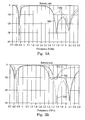
- Fig. 3A is a graph illustrating antenna return loss of the portable communication device 200.
- a network analyzer can be connected to the feeding port of the PIFA 250 by a coaxial cable to measure return loss in different resonant modes, in which the resonant modes are generated by the first metal element 236 and the PIFA 250 or the second metal element 238 and the PIFA 250.
- the return loss within the resonant modes generated by the first metal element 236 and the second metal element 238 are respectively represented by a return loss curve 310 and a return loss curve 320 in Fig. 3A .
- Fig. 2B shows the portable communication device 200 of Fig. 2A in a condition held in a first use position.
- a user's hand 10 may be close to or touch to a touch display module 2103 and the first metal element 236, in which the touch display module 2103 is disposed on a second surface 2102 of the housing 210 (e.g., a front side of the portable communication device 200), and the first metal element 236 is disposed on sides of the housing 210.
- a plurality of resonant modes generated by the PIFA 250 and the first metal element 236 may be interfered with by a parasitic capacitance effect, thereby causing resonant frequency shifts and increasing return loss to, in turn, reduce the communication quality of the portable communication device 200.
- Fig. 3B is a graph illustrating antenna return loss of the portable communication device 200 when held in the first use position shown in Fig. 2B .
- a return loss curve 312 is the return loss measurement result in the first operating mode of the PIFA 250 and the first metal element 236 of the portable communication device 200
- a return loss curve 322 is the return loss measurement result in the first operating mode of the PIFA 250 and the second metal element 238 of the portable communication device 200.
- the portable communication device 200 also has better return loss within the foregoing operating frequency bands, as shown by a return loss curve 322.
- Fig. 2C shows the portable communication device 200 of Fig. 2A in a condition held in a second use position.
- the portable communication device 200 when the portable communication device 200 is held in the second use position, such as when making a call using the portable communication device 200 (a Voice mode), the user's hand 10 may be close to or touch to the second metal element 238 disposed on sides of the housing 210.
- the user's hand 10 is close to or touches the second metal element 238, a plurality of resonant modes generated by the PIFA 250 and the second metal element 238 may be interfered with by a parasitic capacitance effect, thereby causing resonant frequency shifts and increasing return loss to, in turn, reduce the communication quality of the portable communication device 200.
- Fig. 3C is a graph illustrating antenna return loss of the portable communication device 200 when held in the second use position as shown in Fig. 2C .
- a return loss curve 314 is the return loss measurement result in the second operating mode of the PIFA 250 and the first metal element 236 of the portable communication device 200
- a return loss curve 324 is the return loss measurement result in the second operating mode of the PIFA 250 and the second metal element 238 of the portable communication device 200.
- the portable communication device 200 also has better return loss within the foregoing operating frequency bands, as shown by the return loss curve 314.
- the electrical length of the first radiating portion 156 in Fig. 1A is adjustable, so that the resonant frequency of the second resonant mode of the PIFA 150 can be adjusted within either 1710 MHz ⁇ 1990 MHz or 1990 MHz - 2170 MHz depending on the desired application.
- the electrical lengths of the first metal element 136 and the second metal element 138 are also adjustable, so that the resonant frequency of the first resonant mode of the switchable resonant antenna 130 can be adjusted within the operating frequency band of GPS, i.e., 1575 MHz, or the operating frequency band of Bluetooth and/or WiFi, i.e., 2.4 GHz.
- the portable communication device 100 of this disclosure can operate in aforesaid communication frequency bands and thereby conform to the requirements of current wireless communication regulations.
- the sensing unit can detect if a user is close to or touching certain portions of the appearance and accordingly the switching unit can select a suitable resonant metal element, so that the interference caused by users to the resonant frequency and the return loss of antenna resonant mode can be reduced. Therefore, the communication quality of the portable communication device is guaranteed.
Landscapes
- Engineering & Computer Science (AREA)
- Computer Hardware Design (AREA)
- Computer Networks & Wireless Communication (AREA)
- General Engineering & Computer Science (AREA)
- Signal Processing (AREA)
- Support Of Aerials (AREA)
- Transceivers (AREA)
- Telephone Set Structure (AREA)
Claims (14)
- Tragbare Kommunikationsvorrichtung (100, 200), umfassend:ein Gehäuse (110; 210);ein Substrat (120), das in dem Gehäuse angeordnet ist, wobei das Substrat eine Erdungsebene (122) aufweist;eine Antenne (150; 250), die ein Erdungsende (152), das elektrisch mit der Erdungsebene (122) verbunden ist, einen Binspeisungsabschnitt (151) und einen zweiten Verbindungsabschnitt (154) aufweist, der elektrisch mit dem Einspeisungsabschnitt (151) verbunden ist; undeine schaltbare Resonanzantenne (130), die einen ersten Verbindungsabschnitt (132), eine Schalteinheit (134), ein erstes Metallelement (136; 236) und ein zweites Metallelement (138; 238) aufweist, wobeider erste Verbindungsabschnitt (132) elektrisch zwischen die Erdungsebene (122) und die Schalteinheit (134) geschaltet ist,die Schalteinheit (134) ausgelegt ist, um den ersten Verbindungsabschnitt (132) mit dem ersten Metallelement (136; 236) oder dem zweiten Metallelement (138; 238) gemäß einem Steuersignal zu verbinden, undFunkfrequenz-Signale von der tragbaren Kommunikationseinrichtung (100; 200) dem Einspeisungsabschnitt (151) der Antenne (150; 250) zugeführt werden und weiter in das erste oder zweite Metallelement (136, 138; 236, 238) durch die Verbindungswirkung zwischen dem zweiten Verbindungsabschnitt (154) und dem ersten Verbindungsabschnitt (132) eingespeist werden, um einen ersten Resonanzmodus zu erzeugen,wobei das erste Metallelement (136; 236) und das zweite Metallelement (138; 238) als Abschnitte des Gehäuses (110; 210) ausgelegt sind, um die Funkfrequenz-Signale abzustrahlen und zu empfangen, undwobei der erste Verbindungsabschnitt (132) ausgelegt ist, um die Funkfrequenz-Signale gemeinsam mit dem ersten Metallelement (136; 236) oder dem zweiten Metallelement (138; 238) abzustrahlen.
- Tragbare Kommunikationsvorrichtung nach Anspruch 1, wobei ein erster Resonanzhohlraum zwischen dem ersten Metalletement (136; 236) und der Erdungsebene (122) ausgebildet ist, wenn der erste Verbindungsabschnitt (132) elektronisch mit dem ersten Metallelement (136; 236) gekoppelt ist, und wobei ein zweiter Resonanzhohlraum zwischen dem zweiten Metallelement (138; 238) und der Erdungsebene (122) ausgebildet ist, wenn der erste Verbindungsabschnitt (132) elektronisch mit dem zweiten Metallelement (138; 238) gekoppelt ist.
- Tragbare Kommunikationsvorrichtung nach Anspruch 2, wobei das Gehäuse eine Einfassung (112; 212) aufweist, wobei ein erster Spalt (G1) zwischen einem Ende der Einfassung und dem ersten Metallelement (136; 236) ausgebildet ist und wobei ein zweiter Spalt (G2) zwischen dem anderen Ende der Einfassung (112; 212) und dem zweiten Metallelement (138; 238) ausgebildet ist.
- Tragbare Kommunikationsvorrichtung nach Anspruch 3, wobei die Einfassung ein Metall oder Nichtmetall aufweist.
- Tragbare Kommunikationsvorrichtung nach Anspruch 3 oder 4, wobei der erste Spalt (G1) und eine elektronische Länge des ersten Metallelements (136; 236) zum Steuern des ersten Resonanzmodus, der durch den ersten Resonanzhohlraum erzeugt wird, einstellbar sind, und wobei der zweite Spalt (G2) und eine elektronische Länge des zweiten Metallelements (138; 238) zum Steuern des ersten Resonanzmodus, der durch den zweiten Resonanzhohlraum erzeugt wird, einstellbar sind.
- Tragbare Kommunikationsvorrichtung nach einem vorhergehenden Ansprüche, wobei eine effektive elektronische Länge des ersten Metallelements gleich einer effektiven elektronischen Länge des zweiten Metallelements ist.
- Tragbare Kommunikationsvorrichtung nach einem der Ansprüche 4 bis 6, wobei
eine erste Erfassungseinheit (142) benachbart zu dem ersten Spalt (G1) angeordnet ist um zu erfassen, ob ein Objekt sich in der Nähe des ersten Metallelements befindet oder dieses berührt, und um entsprechend ein erstes Erfassungssignal zu erzeugen; und
eine zweite Erfassungseinheit (144) benachbart zu dem zweiten Spalt (G2) angeordnet ist um zu erfassen, ob ein Objekt sich in der Nähe des zweiten Metallelements befindet oder dieses berührt, und um entsprechend ein zweites Erfassungssignal zu erzeugen. - Tragbare Kommunikationsvorrichtung nach Anspruch 7, weiterhin umfassend:eine Steuereinheit, die elektronisch mit der ersten Erfassungseinheit, der zweiten Erfassungseinheit und der Schalteirzheit verbunden ist, um das Steuersignal auf Grundlage der Erfassungssignale zu erzeugen, um einen Schaltungszustand der Schalteinheit zu steuern.
- Tragbare Kommunikationsvorrichtung nach einem der vorhergehenden Ansprüche, weiterhin umfassen:eine planare invertierte F-Antenne (PIFA) (150), die einen Einspeisungsabschnitt (151), das Erdungsende (152), einen zweiten Verbindungsabschnitt (154), einen ersten Abstrahlungsabschnitt (156) und einen zweiten Abstrahlungsabschnitt (158) aufweist, wobeider Einspeisungsabschnitt und das Erdungsende elektronisch mit dem Substrat (120) gekoppelt sind,das Erdungsende elelctronisch mit der Erdungsebene (122) des Substrats (120) gekoppelt ist, undder zweite Verbindungsabschnitt elektronisch mit dem Einspeisungsabschnitt (151), dem Erdungsende (152), dem ersten Abstrahlungsabschnitt (156) und dem zweiten Abstrahlungsabschnitt (158) gekoppelt ist.
- Tragbare Kommunikationsvorrichtung nach Anspruch 9, wobei der erste Abstrahlungsabschnitt (156) auf oder in dem Gehäuse angeordnet ist, um einen zweiten Resonanzmodus zu erzeugen, und wobei der zweite Abstrahlungsabschnitt (158) auf oder in dem Gehäuse angeordnet ist, um einen dritten Resonanzmodus zu erzeugen.
- Tragbare Kommunikationsvorrichtung nach einem der Ansprüche 1 bis 8, wobei die Antenne eine Monopol-Antenne, eine Schleifenantenne, eine Schlitzantenne oder eine invertierte F-Antenne ist, um Resonanzmoden von gewünschten Betriebsfrequenzbändern zu erzeugen.
- Tragbare Kommunikationsvorrichtung nach Anspruch 8, weiterhin umfassend einen Prozessor, der zum Empfangen des ersten und des zweiten Erfassungssignals von der ersten und zweiten Erfassungseinheit (142, 144), zum Verarbeiten des ersten und zweiten Erfassungssignals und zum Senden des verarbeiteten ersten und zweiten Erfassungssignals an die Steuereinheit (146) ausgelegt ist.
- Tragbare Kommunikationsvorrichtung nach einem der vorhergehenden Anspruch, wobei das Gehäuse (210) eine Rückseite und eine Vorderseite mit einem Berührungs-Anzeigemodul aufweist.
- Tragbare Kommunikationsvorrichtung nach Anspruch 13, wobei die Antenne auf der Rückseite angeordnet ist und wobei das erste und zweite Metallelement (236, 238) auf den Seiten des Gehäuses angeordnet sind.
Applications Claiming Priority (1)
| Application Number | Priority Date | Filing Date | Title |
|---|---|---|---|
| US13/304,726 US9160058B2 (en) | 2011-11-28 | 2011-11-28 | Portable communication device |
Publications (2)
| Publication Number | Publication Date |
|---|---|
| EP2597724A1 EP2597724A1 (de) | 2013-05-29 |
| EP2597724B1 true EP2597724B1 (de) | 2014-09-03 |
Family
ID=46085329
Family Applications (1)
| Application Number | Title | Priority Date | Filing Date |
|---|---|---|---|
| EP20120161951 Active EP2597724B1 (de) | 2011-11-28 | 2012-03-29 | Tragbare Kommunikationsvorrichtung |
Country Status (4)
| Country | Link |
|---|---|
| US (2) | US9160058B2 (de) |
| EP (1) | EP2597724B1 (de) |
| CN (1) | CN103138042B (de) |
| TW (1) | TWI505549B (de) |
Families Citing this family (78)
| Publication number | Priority date | Publication date | Assignee | Title |
|---|---|---|---|---|
| KR101801117B1 (ko) | 2011-07-27 | 2017-11-27 | 삼성전자주식회사 | 휴대용 무선 단말기에서 안테나와 센서용 부재로 병행하는 금속체 및 이와 연동하는 장치 |
| KR101666327B1 (ko) * | 2012-08-20 | 2016-10-13 | 노키아 테크놀로지스 오와이 | 안테나 장치 및 그 제조 방법 |
| KR102013588B1 (ko) | 2012-09-19 | 2019-08-23 | 엘지전자 주식회사 | 이동 단말기 |
| CN103534873B (zh) * | 2013-01-16 | 2015-06-17 | 华为终端有限公司 | 多频天线馈电匹配装置、多频天线及无线通信设备 |
| US9502750B2 (en) * | 2013-04-02 | 2016-11-22 | Apple Inc. | Electronic device with reduced emitted radiation during loaded antenna operating conditions |
| TWI539660B (zh) * | 2013-05-03 | 2016-06-21 | 宏碁股份有限公司 | 行動裝置 |
| TWI590525B (zh) * | 2013-06-04 | 2017-07-01 | 群邁通訊股份有限公司 | 天線結構及應用該天線結構的無線通訊裝置 |
| TWI578617B (zh) * | 2013-06-07 | 2017-04-11 | 富智康(香港)有限公司 | 天線組件及應用該天線組件的無線通訊裝置 |
| CN104425880B (zh) * | 2013-08-19 | 2017-12-01 | 宏碁股份有限公司 | 移动装置 |
| US20150070239A1 (en) * | 2013-09-10 | 2015-03-12 | Mediatek Inc. | Antenna |
| TWI557997B (zh) | 2013-10-02 | 2016-11-11 | 宏碁股份有限公司 | 行動通訊裝置 |
| US9203463B2 (en) | 2013-12-13 | 2015-12-01 | Google Technology Holdings LLC | Mobile device with antenna and capacitance sensing system with slotted metal bezel |
| KR101544698B1 (ko) * | 2013-12-23 | 2015-08-17 | 주식회사 이엠따블유 | 내장형 안테나 |
| CN104752825B (zh) * | 2013-12-31 | 2018-07-27 | 深圳富泰宏精密工业有限公司 | 天线结构及应用该天线结构的无线通信装置 |
| US9774073B2 (en) * | 2014-01-16 | 2017-09-26 | Htc Corporation | Mobile device and multi-band antenna structure therein |
| CN104836030B (zh) * | 2014-02-12 | 2019-01-22 | 宏碁股份有限公司 | 移动通信装置 |
| US10122081B2 (en) * | 2014-03-13 | 2018-11-06 | Google Technology Holdings LLC | Hand grip sensor for external chassis antenna |
| WO2015152925A1 (en) * | 2014-04-03 | 2015-10-08 | Hewlett-Packard Development Company, Lp | Sensor pad to capacitively couple to an antenna module |
| US9680223B2 (en) * | 2014-06-26 | 2017-06-13 | Htc Corporation | Mobile device and manufacturing method thereof |
| US9577318B2 (en) * | 2014-08-19 | 2017-02-21 | Apple Inc. | Electronic device with fingerprint sensor and tunable hybrid antenna |
| KR102226173B1 (ko) * | 2014-09-02 | 2021-03-10 | 삼성전자주식회사 | 외부 금속 프레임을 이용한 안테나 및 이를 구비한 전자 장치 |
| CN105490000B (zh) * | 2014-09-19 | 2018-06-19 | 深圳富泰宏精密工业有限公司 | 无线通信装置 |
| WO2016049851A1 (zh) * | 2014-09-30 | 2016-04-07 | 华为技术有限公司 | 一种通信终端 |
| GB2533339A (en) * | 2014-12-17 | 2016-06-22 | Vertu Corp Ltd | Multiband slot antenna system and apparatus |
| US10622702B2 (en) * | 2014-12-26 | 2020-04-14 | Byd Company Limited | Mobile terminal and antenna of mobile terminal |
| CN105811082B (zh) * | 2014-12-31 | 2021-07-20 | 深圳富泰宏精密工业有限公司 | 天线结构及具有该天线结构的无线通信装置 |
| CN104577334B (zh) * | 2015-02-11 | 2017-07-21 | 小米科技有限责任公司 | 天线模块及移动终端 |
| KR102314790B1 (ko) | 2015-02-26 | 2021-10-20 | 삼성전자주식회사 | 안테나 장치를 포함하는 전자 장치 |
| KR102231232B1 (ko) | 2015-02-27 | 2021-03-23 | 삼성전자주식회사 | 안테나 장치 및 그것을 포함하는 전자 장치 |
| CN104811177B (zh) * | 2015-04-17 | 2018-03-13 | 威海市泓淋电子有限公司 | 近接传感装置及具有自适性工作频带调整射频系统 |
| US20160336644A1 (en) * | 2015-05-13 | 2016-11-17 | Chiun Mai Communication Systems, Inc. | Antenna structure and wireless communication device using the same |
| CN106299675B (zh) * | 2015-05-29 | 2020-10-09 | 深圳富泰宏精密工业有限公司 | 天线结构及应用该天线结构的无线通信装置 |
| KR20170011340A (ko) * | 2015-07-22 | 2017-02-02 | 삼성전자주식회사 | 엑스선 디텍터 및 엑스선 촬영장치 |
| KR102396339B1 (ko) * | 2015-08-13 | 2022-05-12 | 삼성전자주식회사 | 안테나 장치 및 그것을 포함하는 전자 장치 |
| KR20170037464A (ko) * | 2015-09-25 | 2017-04-04 | 엘지전자 주식회사 | 이동 단말기 |
| US10908742B2 (en) * | 2015-10-21 | 2021-02-02 | Microsoft Technology Licensing, Llc | Device with grooves in conductive casing |
| WO2017073020A1 (ja) * | 2015-10-30 | 2017-05-04 | パナソニックIpマネジメント株式会社 | 電子機器 |
| TWI577084B (zh) * | 2015-11-25 | 2017-04-01 | 宏碁股份有限公司 | 行動通訊裝置 |
| KR101827275B1 (ko) * | 2015-11-27 | 2018-02-08 | 엘지전자 주식회사 | 이동 단말기 |
| WO2017090997A1 (ko) | 2015-11-27 | 2017-06-01 | 엘지전자 주식회사 | 이동 단말기 |
| KR102552098B1 (ko) * | 2016-02-18 | 2023-07-07 | 삼성전자주식회사 | 안테나 장치 및 이를 포함하는 전자 장치 |
| US10594022B2 (en) | 2016-02-19 | 2020-03-17 | Hewlett-Packard Development Company, L.P. | Triband antenna |
| KR102461035B1 (ko) * | 2016-02-20 | 2022-11-01 | 삼성전자주식회사 | 안테나를 포함하는 전자 장치 |
| WO2017171161A1 (ko) * | 2016-03-28 | 2017-10-05 | 엘지전자 주식회사 | 이동 단말기 |
| CN107275753B (zh) * | 2016-04-08 | 2020-06-19 | 北京小米移动软件有限公司 | 终端的天线 |
| KR102578502B1 (ko) * | 2016-08-01 | 2023-09-15 | 삼성전자주식회사 | 안테나를 포함하는 전자 장치 |
| TWI635656B (zh) * | 2016-08-24 | 2018-09-11 | 耀登科技股份有限公司 | 無線通訊裝置 |
| US10749247B2 (en) | 2016-10-21 | 2020-08-18 | Cavendish Kinetics, Inc. | Multi-resonant antenna structure |
| TWI626789B (zh) * | 2016-11-04 | 2018-06-11 | 群邁通訊股份有限公司 | 天線結構及應用該天線結構之無線通訊裝置 |
| TWI642232B (zh) * | 2016-11-11 | 2018-11-21 | 宏碁股份有限公司 | 行動裝置 |
| KR102573516B1 (ko) | 2016-11-28 | 2023-09-01 | 삼성전자 주식회사 | 안테나를 포함하는 전자 장치 |
| CN108206322B (zh) * | 2016-12-16 | 2020-02-07 | 北京小米移动软件有限公司 | 终端壳体及终端 |
| CN106654558B (zh) * | 2016-12-19 | 2019-11-29 | 北京小米移动软件有限公司 | 移动终端天线及其控制方法和装置 |
| CN113690611B (zh) * | 2016-12-27 | 2024-10-15 | 宏达国际电子股份有限公司 | 移动装置 |
| CN108281791B (zh) * | 2017-01-05 | 2020-12-08 | 深圳富泰宏精密工业有限公司 | 电子装置 |
| KR101884603B1 (ko) * | 2017-01-18 | 2018-08-02 | 조인셋 주식회사 | 모바일 폰에서 안테나의 방사 효율의 저하를 방지하는 자성체 장치 |
| US10951260B2 (en) * | 2017-01-26 | 2021-03-16 | Lg Electronics Inc. | Mobile terminal |
| US10879596B2 (en) * | 2017-01-31 | 2020-12-29 | Intel Corporation | Antenna for wearable devices methods, apparatuses, and systems |
| TWI655804B (zh) * | 2017-08-03 | 2019-04-01 | 廣達電腦股份有限公司 | 通訊裝置 |
| US10700416B2 (en) | 2017-08-30 | 2020-06-30 | Lg Electronics Inc. | Mobile terminal |
| TWI648907B (zh) * | 2017-09-04 | 2019-01-21 | 廣達電腦股份有限公司 | 行動裝置 |
| CN111201672A (zh) * | 2017-10-11 | 2020-05-26 | 维斯普瑞公司 | 使端射天线和低频天线并置的系统、设备和方法 |
| GB201718424D0 (en) * | 2017-11-07 | 2017-12-20 | Taoglas Group Holdings | Acircuit board including a trace antenna |
| CN109980333A (zh) * | 2017-12-27 | 2019-07-05 | 深圳富泰宏精密工业有限公司 | 天线结构及具有该天线结构的无线通信装置 |
| CN110034402B (zh) * | 2018-01-11 | 2021-11-23 | 深圳富泰宏精密工业有限公司 | 天线结构及具有该天线结构的无线通信装置 |
| CN108428993A (zh) * | 2018-03-21 | 2018-08-21 | 上海安费诺永亿通讯电子有限公司 | 一种天线 |
| KR102562550B1 (ko) * | 2018-07-02 | 2023-08-03 | 삼성전자주식회사 | 디스플레이 장치 |
| US10404308B1 (en) * | 2018-08-24 | 2019-09-03 | Motorola Mobility Llc | Millimeter wave antenna management |
| KR102570509B1 (ko) | 2018-10-19 | 2023-08-25 | 삼성전자 주식회사 | 통신 주파수 대역에 기반하여 안테나 장치에 포함된 광도전성 물질의 전기적 상태를 변경하는 전자 장치 및 안테나 제어 방법 |
| CN109659672B (zh) * | 2018-12-12 | 2020-09-11 | 维沃移动通信有限公司 | 一种终端设备 |
| CN110165373B (zh) * | 2019-05-14 | 2021-09-24 | 荣耀终端有限公司 | 天线装置及电子设备 |
| CN111029725B (zh) | 2019-12-31 | 2021-09-24 | 维沃移动通信有限公司 | 一种电子设备 |
| TWI723744B (zh) * | 2020-01-16 | 2021-04-01 | 啟碁科技股份有限公司 | 行動裝置與天線結構 |
| CN113948863B (zh) * | 2020-07-16 | 2025-12-30 | 深圳富泰宏精密工业有限公司 | 信号馈入组件,天线模块及电子设备 |
| CN112310643B (zh) * | 2020-09-03 | 2021-10-29 | 瑞声新能源发展(常州)有限公司科教城分公司 | 天线模组及应用该天线模组的终端设备 |
| CN112072314B (zh) * | 2020-09-07 | 2023-06-06 | 抖音视界有限公司 | 多频天线及电子设备 |
| CN114583454B (zh) * | 2020-11-30 | 2024-11-22 | 华为技术有限公司 | 天线装置及电子设备 |
| TWI827123B (zh) * | 2022-07-06 | 2023-12-21 | 啓碁科技股份有限公司 | 天線結構和通訊裝置 |
Family Cites Families (13)
| Publication number | Priority date | Publication date | Assignee | Title |
|---|---|---|---|---|
| JP2000114856A (ja) | 1998-09-30 | 2000-04-21 | Nec Saitama Ltd | 逆fアンテナおよびそれを用いた無線装置 |
| JP2002217803A (ja) | 2001-01-15 | 2002-08-02 | Nec Access Technica Ltd | 携帯無線端末装置 |
| US6774850B2 (en) | 2002-09-18 | 2004-08-10 | High Tech Computer, Corp. | Broadband couple-fed planar antennas with coupled metal strips on the ground plane |
| KR100617861B1 (ko) * | 2004-06-29 | 2006-08-28 | 주식회사 팬택앤큐리텔 | 듀얼 인테나를 구비한 이동통신 단말기 |
| US7627296B2 (en) * | 2004-10-18 | 2009-12-01 | Research In Motion Limited | Method of controlling a plurality of internal antennas in a mobile communication device |
| FI119009B (fi) * | 2005-10-03 | 2008-06-13 | Pulse Finland Oy | Monikaistainen antennijärjestelmä |
| KR100735319B1 (ko) | 2006-06-20 | 2007-07-04 | 삼성전자주식회사 | 휴대단말기의 안테나 잡음률 보정 방법 및 장치 |
| US7778678B2 (en) | 2006-10-10 | 2010-08-17 | Panasonic Corporation | Radio control device |
| US7612725B2 (en) | 2007-06-21 | 2009-11-03 | Apple Inc. | Antennas for handheld electronic devices with conductive bezels |
| US7705795B2 (en) * | 2007-12-18 | 2010-04-27 | Apple Inc. | Antennas with periodic shunt inductors |
| TWM349049U (en) | 2008-07-18 | 2009-01-11 | Cheng Uei Prec Ind Co Ltd | Multi-band antenna |
| US8406806B2 (en) * | 2010-09-20 | 2013-03-26 | Smartech Worldwide Limited | Mobile telephone capable of automatically switching antenna according to user's hand position |
| TW201328206A (zh) * | 2011-12-30 | 2013-07-01 | Fih Hong Kong Ltd | 無線通訊裝置 |
-
2011
- 2011-11-28 US US13/304,726 patent/US9160058B2/en active Active
-
2012
- 2012-03-01 TW TW101106761A patent/TWI505549B/zh active
- 2012-03-08 CN CN201210063184.7A patent/CN103138042B/zh active Active
- 2012-03-29 EP EP20120161951 patent/EP2597724B1/de active Active
-
2015
- 2015-08-11 US US14/823,112 patent/US10069192B2/en active Active
Also Published As
| Publication number | Publication date |
|---|---|
| CN103138042A (zh) | 2013-06-05 |
| US9160058B2 (en) | 2015-10-13 |
| US20130135157A1 (en) | 2013-05-30 |
| CN103138042B (zh) | 2016-02-03 |
| TWI505549B (zh) | 2015-10-21 |
| EP2597724A1 (de) | 2013-05-29 |
| TW201322543A (zh) | 2013-06-01 |
| US10069192B2 (en) | 2018-09-04 |
| US20150349408A1 (en) | 2015-12-03 |
Similar Documents
| Publication | Publication Date | Title |
|---|---|---|
| EP2597724B1 (de) | Tragbare Kommunikationsvorrichtung | |
| CN110190397B (zh) | 电子设备和手表 | |
| US10965008B2 (en) | Electronic device with housing slots for antennas | |
| EP3373392B1 (de) | Antennenmodul und elektronische vorrichtung damit | |
| US11088470B2 (en) | Antenna device and mobile terminal having the same | |
| US20220094043A1 (en) | Tunable Antenna System for Smart Watch | |
| US10211512B2 (en) | Multi-band antenna on the surface of wireless communication devices | |
| KR101916241B1 (ko) | 휴대용 단말기의 안테나 장치 | |
| US11817916B2 (en) | Systems and methods for establishing reliable wireless links | |
| US9240627B2 (en) | Handheld device and planar antenna thereof | |
| US10950932B1 (en) | Electronic device wide band antennas | |
| CN110336118B (zh) | 可穿戴设备以及智能手表 | |
| US20210096515A1 (en) | Electronic Device Wide Band Antennas | |
| US8823592B2 (en) | Antenna array with capacitive coupled upper and lower antenna elements and a peak radiation pattern directed toward the lower antenna element | |
| CN112350057B (zh) | 具有多频带天线的电子设备 | |
| US20110128190A1 (en) | Wireless communication terminal with a split multi-band antenna having a single rf feed node | |
| US20140134958A1 (en) | Dual Feed Antenna System | |
| US9496603B2 (en) | Electronic apparatus | |
| US20110206097A1 (en) | Terminals and antenna systems with a primary radiator line capacitively excited by a secondary radiator line | |
| US8378899B2 (en) | Wireless communication terminal with a multi-band antenna that extends between side surfaces thereof | |
| WO2006013843A1 (ja) | 携帯電話機 | |
| EP2775562B1 (de) | Kommunikationsvorrichtung und Antennenelement darin | |
| CN120566055A (zh) | 一种可穿戴设备及其控制方法 |
Legal Events
| Date | Code | Title | Description |
|---|---|---|---|
| PUAI | Public reference made under article 153(3) epc to a published international application that has entered the european phase |
Free format text: ORIGINAL CODE: 0009012 |
|
| 17P | Request for examination filed |
Effective date: 20120329 |
|
| AK | Designated contracting states |
Kind code of ref document: A1 Designated state(s): AL AT BE BG CH CY CZ DE DK EE ES FI FR GB GR HR HU IE IS IT LI LT LU LV MC MK MT NL NO PL PT RO RS SE SI SK SM TR |
|
| AX | Request for extension of the european patent |
Extension state: BA ME |
|
| 17Q | First examination report despatched |
Effective date: 20140124 |
|
| GRAP | Despatch of communication of intention to grant a patent |
Free format text: ORIGINAL CODE: EPIDOSNIGR1 |
|
| INTG | Intention to grant announced |
Effective date: 20140703 |
|
| GRAS | Grant fee paid |
Free format text: ORIGINAL CODE: EPIDOSNIGR3 |
|
| GRAA | (expected) grant |
Free format text: ORIGINAL CODE: 0009210 |
|
| AK | Designated contracting states |
Kind code of ref document: B1 Designated state(s): AL AT BE BG CH CY CZ DE DK EE ES FI FR GB GR HR HU IE IS IT LI LT LU LV MC MK MT NL NO PL PT RO RS SE SI SK SM TR |
|
| REG | Reference to a national code |
Ref country code: GB Ref legal event code: FG4D |
|
| REG | Reference to a national code |
Ref country code: CH Ref legal event code: EP Ref country code: AT Ref legal event code: REF Ref document number: 686005 Country of ref document: AT Kind code of ref document: T Effective date: 20140915 |
|
| REG | Reference to a national code |
Ref country code: IE Ref legal event code: FG4D |
|
| REG | Reference to a national code |
Ref country code: DE Ref legal event code: R096 Ref document number: 602012002931 Country of ref document: DE Effective date: 20141016 |
|
| REG | Reference to a national code |
Ref country code: NL Ref legal event code: T3 |
|
| REG | Reference to a national code |
Ref country code: AT Ref legal event code: MK05 Ref document number: 686005 Country of ref document: AT Kind code of ref document: T Effective date: 20140903 |
|
| PG25 | Lapsed in a contracting state [announced via postgrant information from national office to epo] |
Ref country code: LT Free format text: LAPSE BECAUSE OF FAILURE TO SUBMIT A TRANSLATION OF THE DESCRIPTION OR TO PAY THE FEE WITHIN THE PRESCRIBED TIME-LIMIT Effective date: 20140903 Ref country code: FI Free format text: LAPSE BECAUSE OF FAILURE TO SUBMIT A TRANSLATION OF THE DESCRIPTION OR TO PAY THE FEE WITHIN THE PRESCRIBED TIME-LIMIT Effective date: 20140903 Ref country code: SE Free format text: LAPSE BECAUSE OF FAILURE TO SUBMIT A TRANSLATION OF THE DESCRIPTION OR TO PAY THE FEE WITHIN THE PRESCRIBED TIME-LIMIT Effective date: 20140903 Ref country code: ES Free format text: LAPSE BECAUSE OF FAILURE TO SUBMIT A TRANSLATION OF THE DESCRIPTION OR TO PAY THE FEE WITHIN THE PRESCRIBED TIME-LIMIT Effective date: 20140903 Ref country code: NO Free format text: LAPSE BECAUSE OF FAILURE TO SUBMIT A TRANSLATION OF THE DESCRIPTION OR TO PAY THE FEE WITHIN THE PRESCRIBED TIME-LIMIT Effective date: 20141203 Ref country code: GR Free format text: LAPSE BECAUSE OF FAILURE TO SUBMIT A TRANSLATION OF THE DESCRIPTION OR TO PAY THE FEE WITHIN THE PRESCRIBED TIME-LIMIT Effective date: 20141204 |
|
| REG | Reference to a national code |
Ref country code: LT Ref legal event code: MG4D |
|
| PG25 | Lapsed in a contracting state [announced via postgrant information from national office to epo] |
Ref country code: AT Free format text: LAPSE BECAUSE OF FAILURE TO SUBMIT A TRANSLATION OF THE DESCRIPTION OR TO PAY THE FEE WITHIN THE PRESCRIBED TIME-LIMIT Effective date: 20140903 Ref country code: RS Free format text: LAPSE BECAUSE OF FAILURE TO SUBMIT A TRANSLATION OF THE DESCRIPTION OR TO PAY THE FEE WITHIN THE PRESCRIBED TIME-LIMIT Effective date: 20140903 Ref country code: LV Free format text: LAPSE BECAUSE OF FAILURE TO SUBMIT A TRANSLATION OF THE DESCRIPTION OR TO PAY THE FEE WITHIN THE PRESCRIBED TIME-LIMIT Effective date: 20140903 Ref country code: CY Free format text: LAPSE BECAUSE OF FAILURE TO SUBMIT A TRANSLATION OF THE DESCRIPTION OR TO PAY THE FEE WITHIN THE PRESCRIBED TIME-LIMIT Effective date: 20140903 Ref country code: HR Free format text: LAPSE BECAUSE OF FAILURE TO SUBMIT A TRANSLATION OF THE DESCRIPTION OR TO PAY THE FEE WITHIN THE PRESCRIBED TIME-LIMIT Effective date: 20140903 |
|
| REG | Reference to a national code |
Ref country code: CH Ref legal event code: PCOW Free format text: NEW ADDRESS: NO. 23, XINGHUA ROAD TAOYUAN DISTRICT, TAOYUAN CITY 330 (TW) |
|
| REG | Reference to a national code |
Ref country code: FR Ref legal event code: PLFP Year of fee payment: 4 |
|
| RAP2 | Party data changed (patent owner data changed or rights of a patent transferred) |
Owner name: HTC CORPORATION |
|
| PG25 | Lapsed in a contracting state [announced via postgrant information from national office to epo] |
Ref country code: PT Free format text: LAPSE BECAUSE OF FAILURE TO SUBMIT A TRANSLATION OF THE DESCRIPTION OR TO PAY THE FEE WITHIN THE PRESCRIBED TIME-LIMIT Effective date: 20150105 Ref country code: EE Free format text: LAPSE BECAUSE OF FAILURE TO SUBMIT A TRANSLATION OF THE DESCRIPTION OR TO PAY THE FEE WITHIN THE PRESCRIBED TIME-LIMIT Effective date: 20140903 Ref country code: SK Free format text: LAPSE BECAUSE OF FAILURE TO SUBMIT A TRANSLATION OF THE DESCRIPTION OR TO PAY THE FEE WITHIN THE PRESCRIBED TIME-LIMIT Effective date: 20140903 Ref country code: IS Free format text: LAPSE BECAUSE OF FAILURE TO SUBMIT A TRANSLATION OF THE DESCRIPTION OR TO PAY THE FEE WITHIN THE PRESCRIBED TIME-LIMIT Effective date: 20150103 Ref country code: RO Free format text: LAPSE BECAUSE OF FAILURE TO SUBMIT A TRANSLATION OF THE DESCRIPTION OR TO PAY THE FEE WITHIN THE PRESCRIBED TIME-LIMIT Effective date: 20140903 Ref country code: CZ Free format text: LAPSE BECAUSE OF FAILURE TO SUBMIT A TRANSLATION OF THE DESCRIPTION OR TO PAY THE FEE WITHIN THE PRESCRIBED TIME-LIMIT Effective date: 20140903 |
|
| PG25 | Lapsed in a contracting state [announced via postgrant information from national office to epo] |
Ref country code: PL Free format text: LAPSE BECAUSE OF FAILURE TO SUBMIT A TRANSLATION OF THE DESCRIPTION OR TO PAY THE FEE WITHIN THE PRESCRIBED TIME-LIMIT Effective date: 20140903 |
|
| REG | Reference to a national code |
Ref country code: DE Ref legal event code: R097 Ref document number: 602012002931 Country of ref document: DE |
|
| PLBE | No opposition filed within time limit |
Free format text: ORIGINAL CODE: 0009261 |
|
| STAA | Information on the status of an ep patent application or granted ep patent |
Free format text: STATUS: NO OPPOSITION FILED WITHIN TIME LIMIT |
|
| PG25 | Lapsed in a contracting state [announced via postgrant information from national office to epo] |
Ref country code: DK Free format text: LAPSE BECAUSE OF FAILURE TO SUBMIT A TRANSLATION OF THE DESCRIPTION OR TO PAY THE FEE WITHIN THE PRESCRIBED TIME-LIMIT Effective date: 20140903 |
|
| 26N | No opposition filed |
Effective date: 20150604 |
|
| PG25 | Lapsed in a contracting state [announced via postgrant information from national office to epo] |
Ref country code: IT Free format text: LAPSE BECAUSE OF FAILURE TO SUBMIT A TRANSLATION OF THE DESCRIPTION OR TO PAY THE FEE WITHIN THE PRESCRIBED TIME-LIMIT Effective date: 20140903 |
|
| PG25 | Lapsed in a contracting state [announced via postgrant information from national office to epo] |
Ref country code: LU Free format text: LAPSE BECAUSE OF FAILURE TO SUBMIT A TRANSLATION OF THE DESCRIPTION OR TO PAY THE FEE WITHIN THE PRESCRIBED TIME-LIMIT Effective date: 20150329 Ref country code: MC Free format text: LAPSE BECAUSE OF FAILURE TO SUBMIT A TRANSLATION OF THE DESCRIPTION OR TO PAY THE FEE WITHIN THE PRESCRIBED TIME-LIMIT Effective date: 20140903 |
|
| REG | Reference to a national code |
Ref country code: CH Ref legal event code: PL |
|
| PG25 | Lapsed in a contracting state [announced via postgrant information from national office to epo] |
Ref country code: SI Free format text: LAPSE BECAUSE OF FAILURE TO SUBMIT A TRANSLATION OF THE DESCRIPTION OR TO PAY THE FEE WITHIN THE PRESCRIBED TIME-LIMIT Effective date: 20140903 |
|
| REG | Reference to a national code |
Ref country code: IE Ref legal event code: MM4A |
|
| PG25 | Lapsed in a contracting state [announced via postgrant information from national office to epo] |
Ref country code: LI Free format text: LAPSE BECAUSE OF NON-PAYMENT OF DUE FEES Effective date: 20150331 Ref country code: CH Free format text: LAPSE BECAUSE OF NON-PAYMENT OF DUE FEES Effective date: 20150331 Ref country code: IE Free format text: LAPSE BECAUSE OF NON-PAYMENT OF DUE FEES Effective date: 20150329 |
|
| REG | Reference to a national code |
Ref country code: FR Ref legal event code: PLFP Year of fee payment: 5 |
|
| PG25 | Lapsed in a contracting state [announced via postgrant information from national office to epo] |
Ref country code: BE Free format text: LAPSE BECAUSE OF FAILURE TO SUBMIT A TRANSLATION OF THE DESCRIPTION OR TO PAY THE FEE WITHIN THE PRESCRIBED TIME-LIMIT Effective date: 20140903 |
|
| PG25 | Lapsed in a contracting state [announced via postgrant information from national office to epo] |
Ref country code: MT Free format text: LAPSE BECAUSE OF FAILURE TO SUBMIT A TRANSLATION OF THE DESCRIPTION OR TO PAY THE FEE WITHIN THE PRESCRIBED TIME-LIMIT Effective date: 20140903 |
|
| REG | Reference to a national code |
Ref country code: FR Ref legal event code: PLFP Year of fee payment: 6 |
|
| PG25 | Lapsed in a contracting state [announced via postgrant information from national office to epo] |
Ref country code: SM Free format text: LAPSE BECAUSE OF FAILURE TO SUBMIT A TRANSLATION OF THE DESCRIPTION OR TO PAY THE FEE WITHIN THE PRESCRIBED TIME-LIMIT Effective date: 20140903 Ref country code: BG Free format text: LAPSE BECAUSE OF FAILURE TO SUBMIT A TRANSLATION OF THE DESCRIPTION OR TO PAY THE FEE WITHIN THE PRESCRIBED TIME-LIMIT Effective date: 20140903 Ref country code: HU Free format text: LAPSE BECAUSE OF FAILURE TO SUBMIT A TRANSLATION OF THE DESCRIPTION OR TO PAY THE FEE WITHIN THE PRESCRIBED TIME-LIMIT; INVALID AB INITIO Effective date: 20120329 |
|
| PG25 | Lapsed in a contracting state [announced via postgrant information from national office to epo] |
Ref country code: TR Free format text: LAPSE BECAUSE OF FAILURE TO SUBMIT A TRANSLATION OF THE DESCRIPTION OR TO PAY THE FEE WITHIN THE PRESCRIBED TIME-LIMIT Effective date: 20140903 |
|
| REG | Reference to a national code |
Ref country code: FR Ref legal event code: PLFP Year of fee payment: 7 |
|
| PG25 | Lapsed in a contracting state [announced via postgrant information from national office to epo] |
Ref country code: MK Free format text: LAPSE BECAUSE OF FAILURE TO SUBMIT A TRANSLATION OF THE DESCRIPTION OR TO PAY THE FEE WITHIN THE PRESCRIBED TIME-LIMIT Effective date: 20140903 |
|
| PG25 | Lapsed in a contracting state [announced via postgrant information from national office to epo] |
Ref country code: AL Free format text: LAPSE BECAUSE OF FAILURE TO SUBMIT A TRANSLATION OF THE DESCRIPTION OR TO PAY THE FEE WITHIN THE PRESCRIBED TIME-LIMIT Effective date: 20140903 |
|
| P01 | Opt-out of the competence of the unified patent court (upc) registered |
Effective date: 20230602 |
|
| PGFP | Annual fee paid to national office [announced via postgrant information from national office to epo] |
Ref country code: FR Payment date: 20251231 Year of fee payment: 15 |
|
| PGFP | Annual fee paid to national office [announced via postgrant information from national office to epo] |
Ref country code: NL Payment date: 20260106 Year of fee payment: 15 |
|
| PGFP | Annual fee paid to national office [announced via postgrant information from national office to epo] |
Ref country code: GB Payment date: 20260106 Year of fee payment: 15 |
|
| PGFP | Annual fee paid to national office [announced via postgrant information from national office to epo] |
Ref country code: DE Payment date: 20260102 Year of fee payment: 15 |