EP2597392A2 - Klimaanlage - Google Patents
Klimaanlage Download PDFInfo
- Publication number
- EP2597392A2 EP2597392A2 EP12188085.0A EP12188085A EP2597392A2 EP 2597392 A2 EP2597392 A2 EP 2597392A2 EP 12188085 A EP12188085 A EP 12188085A EP 2597392 A2 EP2597392 A2 EP 2597392A2
- Authority
- EP
- European Patent Office
- Prior art keywords
- channel
- air
- perforated channel
- perforated
- channelling
- Prior art date
- Legal status (The legal status is an assumption and is not a legal conclusion. Google has not performed a legal analysis and makes no representation as to the accuracy of the status listed.)
- Granted
Links
Images

Classifications
-
- F—MECHANICAL ENGINEERING; LIGHTING; HEATING; WEAPONS; BLASTING
- F24—HEATING; RANGES; VENTILATING
- F24F—AIR-CONDITIONING; AIR-HUMIDIFICATION; VENTILATION; USE OF AIR CURRENTS FOR SCREENING
- F24F13/00—Details common to, or for air-conditioning, air-humidification, ventilation or use of air currents for screening
- F24F13/02—Ducting arrangements
- F24F13/06—Outlets for directing or distributing air into rooms or spaces, e.g. ceiling air diffuser
- F24F13/065—Outlets for directing or distributing air into rooms or spaces, e.g. ceiling air diffuser formed as cylindrical or spherical bodies which are rotatable
-
- F—MECHANICAL ENGINEERING; LIGHTING; HEATING; WEAPONS; BLASTING
- F24—HEATING; RANGES; VENTILATING
- F24F—AIR-CONDITIONING; AIR-HUMIDIFICATION; VENTILATION; USE OF AIR CURRENTS FOR SCREENING
- F24F13/00—Details common to, or for air-conditioning, air-humidification, ventilation or use of air currents for screening
- F24F13/02—Ducting arrangements
- F24F13/06—Outlets for directing or distributing air into rooms or spaces, e.g. ceiling air diffuser
- F24F2013/0608—Perforated ducts
Definitions
- the present invention relates to an apparatus for air treatment and diffusion of air.
- the present invention is applicable in the conditioning of environments such as swimming pools, offices, large workshops, etc., by means of air treatment plants which exploit perforated channels for diffusing air into environments by an inductive effect, i.e. in order to obtain a pulsion of the environmental air.
- present apparatus for air conditioning use special metal channellings which have the task of transporting the air into the zones of interest and diffusing the air such as to condition the air external of the channel.
- one or more devices for generating a flow of delivery air internally of the channels are connected such as to increase the pressure internally thereof.
- High-velocity air flows are generated in specially-perforated metal conduits, or diffusers, which diffusers recall, by inductive effect, the air surrounding the channel, thus creating a mixture of the ambient air with the treated air and extremely efficiently conditioning the room.
- the spatial configuration and arrangement internally of the room of the metal channellings and in particular the positioning and orientation of the diffusers can in general be of any type, such as to optimise the volumes of treated air, as well as the homogenisation of the temperatures.
- the air treatment unit injects a flow at a central zone of the header such that the flow divides on the two branches, left and right, of the header and then arrives at the distribution channels, where it is appropriately shared out.
- the basic principle of this type of perforated channel consists in using the delivery air for moving the totality of the ambient air volume in the desired direction and at the desired velocity.
- the perforated channels create a pressure field along the axis thereof such as to be able to impart a thrust on the totality of the ambient air mass. Since the fluid air layers in delivery have necessarily to exit from the holes with a micro-turbulent flow destined to create a strong depression about the base of the hole such as to recall by induction a quantity of ambient air that is much greater than the delivery air, the dimensioning of the holes and their distribution thereof along the pulsion channel is an extremely delicate matter, especially with the aim of avoiding the generation of annoying draughts at ground level.
- channellings designed mainly for injecting rather large volumes of air into environments, which do not however destined create substantial inductive effects, but only transfer energy into the environment.
- induction diffuser channels in general exhibit predetermined development directions along which different-diameter perforations are made.
- an optimal launch angle of the air is established, which can enable effective mixing of the air injected into the environment with the air of the actual ambient, as well as enabling destratification, thus obtaining an air conditioning that is effective and homogeneous internally of the environment.
- solutions according to the state of the art include turning off part of the plant during the winter season so that it can guarantee correct heating of the ambient; conversely, in the summer season the plant is generally used at its maximum power.
- the compensated ring technology of EP no. 2244022 can be used, which, however, once more can lead to the need to isolate a part of the plant and/or turn of some diffuser units.
- ground draughts for limited times such as, for example, to enable one or more rapid adjustments of the plant.
- This operation can today be done by closing some air diffuser tracts of the plant, i.e. reducing the active parts of the plants with a same total volume of delivery air such as to increase the launch velocity. In plants where this cannot be done, it is not possible to increase the performance during the adjustment period to normal functioning.
- An aim of the present invention is therefore substantially to obviate the above-cited drawbacks.
- a first aim of the invention is to notably increase the operating flexibility of known apparatus without however leading to significant increases in costs and plant structures.
- a further auxiliary aim of the invention is to disclose an apparatus for air treatment that is simply configurable in order to be optimised in both winter and summer seasons, but also to be able to vary the operating conditions in a very simple and effective way, for example at start-up transitory stage where it can be necessary to perform a rapid destratification, even in the presence of ground draughts, and a configuration of normal operation in which optimal mixing of the treated air with the ambient air has to be guaranteed, without however leading to ground draughts.
- a possible further objective according to the description of embodiments presented in the following is to enable a simpler regulating of the functioning of the plant which takes account of the situations connected with the seasonal issue, any design errors and/or modifications of the ambient configuration into which the treated air is to be injected, for example following modifications in the distribution of the spaces in the treated environment.
- reference numeral 1 denotes in its entirety an apparatus for air treatment and in particular for the conditioning of rooms.
- the conveyor channelling 6 is constituted by a number of tubular modules (possibly with different sections) suitably joined together such as to transport the treated air coming from the treatment unit 2 (or from treatment units when there is more than one of them) to the environment where, through suitable speakers, air can be introduced into the environment to be conditioned.
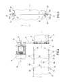
- the example of figure 1 shows a conveyor channelling 6 which comprises a main channel 29 which receives the air directly from the fan 2 and conveys it to a predetermined number of secondary channellings 30 (only one of which is represented in the accompanying figures) by the use of suitable node modules 31 which deviate air from the main channelling 29 and deflect it towards the secondary channellings 30.
- the main channelling exhibits a square or rectangular section, while the secondary channellings 30 have a circular cross-section.
- the node module 31 connects the various portions and sections of the channelling 6.
- FIG. 1 shows, in a schematic view and in longitudinal section, a possible coupling system 25 between the end 6a of the channelling 6 and the corresponding end of the third perforated channelling 3.
- the coupling system is configured in such a way as to enable a relative rotation of the above-mentioned ends 3a, 6a about a longitudinal axis 5, while substantially preventing axial sliding along the same axis.
- one end of the perforated channel 3 is inserted inside the corresponding end 6a of the channel 6.
- the opposite configuration, with the end 3a of the perforated channel external of the channel 6 is alternatively possible.
- the respective ends 3a, 6a can exhibit a circular cross-section with different diameters, in such a way as to define an annular gap 26 interposed between the inner surface of the external channelling and the outer surface of the inner channelling.
- one or more rolling couplings 27 will be inserted in the annular cavity 26, for example at longitudinally-spaced cross-sections, such as to determine a stable rotation coupling between the conduit 6 and the perforated transport channelling 3.
- the embodiment illustrated in figure 2 indicates the presence of annular projections 32, 33 defined both at the end 6a of the channel 6 and at both ends 3a of the perforated channel 3.
- these projections in longitudinal section define the respective semicircular seatings facing one another and destined to receive the above-mentioned rolling couplings 27, for example ball bearings, rotating bushings or other.
- the above-mentioned projections 32, 33 can be facing in the same direction, i.e. both outward-facing or both inward-facing, so as to define substantially complementarily-shaped surfaces intended to couple when the plant is assembled.
- the projections define reciprocally-coupling ribs enabling the above-mentioned relative rotation about the longitudinal axis 5, while preventing a relative translation of the ends 3a, 6a along a same axis.
- coupling and coupling systems 25 are possible as long as they allow the above-mentioned degree of rotational freedom and a substantial longitudinal constraint.
- Small movements along the axis 5 of the respective ends 3a, 6a can be allowed, for example by means of screw couplings or similar.
- the channel 6, constituted by the said modules are made of rigid material, such as a metal material.
- the modules defining the channel 6 can be obtained by suitably bent or curved metal sheeting.
- the sections of the ends 3a and 6a can also not be circular provided that a relative at least partial rotation by a predetermined angle established a priori is allowed.
- the perforated channel 3 is constituted by a predetermined number of tubular modules 20 arranged consecutively to one another and appropriately joined.
- Figure 1 shows in particular three perforated modules 20 consecutive to one another.
- the number of modules 20 can be any according to design requirements and the conditioning needs of the environment.
- perforated modules 20 can be alternated with non-perforated sections of channelling where treated air is simply to be conveyed and not introduced into the environment in certain sections of the channelling 3.
- the perforated channelling 3 exhibits the above-mentioned through-holes 4 which can exhibit different passage areas suitably arranged to ensure the inductive effects described below.
- the special perforations applied include two types of holes: induction holes that are smaller and decide the amount of ambient air to be mixed with the air flow; and guide holes that are larger and decide what direction, speed and distance to convey the mass of pre-mixed ambient air from the induction holes.
- the fluid draughts of the delivery air exit the holes with a micro-turbulent flow that creates a deep depression around the base of the hole by recalling, via induction, a quantity of ambient air which in general terms might reach thirty times higher than the delivery air.
- both the induction holes and the guide holes, and in general the holes 4 are such as to define a significant pressure increase localised at the holes themselves.
- the air coming from the holes causes a micro-turbulent induction flow.
- a high-induction diffusion of air is obtained, causing a large-scale mixing of the supply air and the ambient air.
- the higher the induction the shorter the launch greatly limiting installation heights, particularly in the winter season when the temperature of introduction is higher than ambient temperature.
- the flow direction exiting from the above-mentioned holes define an angle with respect to a reference plane, for example a horizontal plane referred to as the launch angle.
- the launch angle ⁇ is substantially defined by the geometry and positioning of the perforated holes on the module 20 of the perforated channel 3.
- the plurality of consecutive tubular modules 20 exhibit, at respective ends 20a and 20b, a terminal edge 22 emerging radially from the longitudinal lateral surface 23 of the module 21 distancingly from the respective development axis.
- the emerging end edges 22 of opposite ends of adjacent modules 21 are facing and substantially in contact with one another.
- the coupling of successive modules 21 takes place through the adoption of a rigid constraint device 21 configured such as to join the facing ends of consecutive modules.
- the rigid constraining device 21 guarantees solidarity in movement to two consecutive modules 20, both in the axial direction along the axis of development 5 and in rotation with respect to the axis thereof.
- the rigid constraint device 21 is constituted by a suitable strap, such as a metal clamp, having a sectional shape which is such as to be complementary with and embrace the two emerging end edges 23 of successive modules and to tighten them to one another so as to define a solid coupling thereof.
- the strap is wrapped externally around the end edges 21 a, 21 b and straddles the projections 22 before being tightened with an appropriate key or adjusting system.
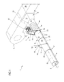
- the system also includes a movement device 7 directly or indirectly active on the perforated channel 3 such as to vary a relative angular position with respect to the conveyor channelling 6.
- the handling device 7 is provided with at least an actuator 8, such as for example a suitable motor, which via a transmission system 9 imparts rotary motion to the perforated channelling 3.
- the transmission system 9 comprises a suitable revolution-reducing device for the engine and transmits motion to a rotary drive pulley 15 mobile in rotation about a respective axis 28 that will be in general terms parallel to the longitudinal axis 5 of the channel 3.
- the drive pulley 15 transfers motion by means of a belt 10.
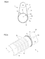
- the belt 10 has a respective coupling portion that is at least partially engaged to a corresponding coupling portion 12 present on the external surface 13 of the perforated channel 3 ( figure 4 ).
- the movement device 7 can transfer the motion of the actuator 8 to the perforated channel 3 such as to determine at least an angular rotation varying the launch angle ⁇ of the air into the ambient.
- the movement device 7 is able to configure the channelling 3 in a plurality of different operational configurations with different launch angles ⁇ of the air into the environment.
- figures 8A and 8B illustrate two different operating conditions achieved by the channel 3 as a result of a movement via the device 7.
- the coupling portion 12 of the perforated channel 3 is defined by a profiled element 14, separate and rigidly connected externally to the channelling, in such a way as to be solid in motion therewith.
- the profiled element 14 could be defined by a rubber or metal strap wound on the external surface 13 of the respective module 20.
- the shaped element 14 may completely surround the external circumference of the channel 3 as shown in figure 4 for example and be constrained by a suitable clamping 34 constituted, for example, by a screw or a rivet that couples one and/or another end of the shaped element 14 to the section of channelling 3.
- the surface of the profiled element 14 is complementarily shaped 12a, at least at the coupling portion 12 of the channel 3.
- the profiled represented as trapezoidal in section, is entirely exemplary. The profiling is illustrated over the whole development of the profiled element 14, i.e. by 360°, but might alternatively only be present at one or more portions of the circular surface of the profiled element 14. The important thing is to ensure a proper coupling with the belt 10 in order to reach the desired angular positions for which the device is intended. Additionally, it can be seen that the profiled element 14 extends, in figure 4 , over an angle of approximately 360°. The profiled element might extend only over an arc of a circle with an opening of 15°, or at least 45° or at least 90°.
- the belt 10 is defined by a closed loop which externally embraces the perforated channel 3 to which motion is to be imparted.
- the belt 10 can be constituted solely by a portion of the loop that goes from the rotating pulley 15 up to the coupling portion 12 of the perforated channel 3. In this situation an end of the belt 10 will be constrained to the rotary pulley 15, while the other end will be constrained to the surface 13 of the channelling 3.
- Two belts 10 may of course be included, defined by portions that extend between the rotary pulley 15 and a left end of the channel 3 between the pulley 15 and a right end of the channel.
- Two or more movement devices 7 may also be present, according to design requirements, in particular in relation to the dimensions and the length of the channelling 3 to be moved. Obviously, the movement devices 7 can be synchronized such as to move the perforated channel 3 with the same launch angle ⁇ variation along the entire longitudinal development 5, or can be independent such as to be able to vary the launch angle ⁇ in a different way at different modules of the channel 3.
- the belt 10 has been represented in figure 4 as having respective complementarily-shaped surfaces 12a over the entire development of the ring. Obviously the profiled elements 12a will be present only at certain portions of the belt itself.
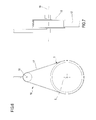
- the suspension system 16 comprises at least an auxiliary belt 17 and at least an idle pulley 18 to which the auxiliary belt 17 is engaged.
- the pulley 18 is located superiorly of the perforated channel 3, and has a rotation axis of 19 substantially parallel to the longitudinal axis 5 of the perforated channel 3.
- the belt 17 generally has a flat surface with a rectangular section, for example, and is destined simply to enable support of the channel and rotation thereof.
- the auxiliary belt 17 of the suspension system 16 is also defined by a closed loop and externally embraces the perforated channel 3 so as to support it and enable the degree of rotational freedom.
- the described embodiment of the treatment apparatus attains important advantages.
- the system is arranged so as to be able to vary at will the launch angle of perforated channels 3 of respective modules 20 according to requirements.
- the launch angle can be increased when setting the system, for example at start-up thereof in the winter when the air needs to be mixed rapidly and where ground draughts can only be tolerated for short times. In fact in this way the cold air present at the floor level of the ambient is more rapidly mixed and homogenized, thus improving the initial performance of the system.
- the adjustment of the launch angle can be carried out to correct any design errors which may have generated ground draughts, i.e. it can also be used to take account of any variations in the environment to be conditioned, for example related to the realisation of new spaces or the positioning of furniture or the like.
Landscapes
- Engineering & Computer Science (AREA)
- Chemical & Material Sciences (AREA)
- Combustion & Propulsion (AREA)
- Mechanical Engineering (AREA)
- General Engineering & Computer Science (AREA)
- Duct Arrangements (AREA)
- Air Conditioning Control Device (AREA)
- Ventilation (AREA)
Applications Claiming Priority (1)
| Application Number | Priority Date | Filing Date | Title |
|---|---|---|---|
| ITMI20110319 ITMI20110319U1 (it) | 2011-10-11 | 2011-10-11 | Impianto per il trattamento di aria, in particolare per il condizionamento di ambienti |
Publications (3)
| Publication Number | Publication Date |
|---|---|
| EP2597392A2 true EP2597392A2 (de) | 2013-05-29 |
| EP2597392A3 EP2597392A3 (de) | 2014-06-18 |
| EP2597392B1 EP2597392B1 (de) | 2018-12-12 |
Family
ID=45956218
Family Applications (1)
| Application Number | Title | Priority Date | Filing Date |
|---|---|---|---|
| EP12188085.0A Active EP2597392B1 (de) | 2011-10-11 | 2012-10-11 | klimaanlage |
Country Status (2)
| Country | Link |
|---|---|
| EP (1) | EP2597392B1 (de) |
| IT (1) | ITMI20110319U1 (de) |
Cited By (2)
| Publication number | Priority date | Publication date | Assignee | Title |
|---|---|---|---|---|
| JP2020003150A (ja) * | 2018-06-28 | 2020-01-09 | 大和ハウス工業株式会社 | 吹出し機構および送風装置 |
| EP4283209A1 (de) | 2022-05-24 | 2023-11-29 | Zeffiro S.r.l. | Luftkanal mit löchern variabler geometrie und zugehörige rohrleitung |
Citations (1)
| Publication number | Priority date | Publication date | Assignee | Title |
|---|---|---|---|---|
| EP2244022A1 (de) | 2009-04-14 | 2010-10-27 | Marco Zambolin | Vorrichtung zur Luftbehandlung |
Family Cites Families (4)
| Publication number | Priority date | Publication date | Assignee | Title |
|---|---|---|---|---|
| US4357860A (en) * | 1980-10-27 | 1982-11-09 | Mccormick-Morgan, Inc. | Telescoping conduit for pressurized air |
| US5111739A (en) * | 1989-11-13 | 1992-05-12 | Hall James F | Air flow control system |
| CA2261538A1 (en) * | 1999-02-15 | 2000-08-15 | Bernt I. Ivarsson | Ventilation duct tubing |
| US6960130B2 (en) * | 2003-05-12 | 2005-11-01 | Rite-Hite Holding Corporation | Fabric air duct with directional vent |
-
2011
- 2011-10-11 IT ITMI20110319 patent/ITMI20110319U1/it unknown
-
2012
- 2012-10-11 EP EP12188085.0A patent/EP2597392B1/de active Active
Patent Citations (1)
| Publication number | Priority date | Publication date | Assignee | Title |
|---|---|---|---|---|
| EP2244022A1 (de) | 2009-04-14 | 2010-10-27 | Marco Zambolin | Vorrichtung zur Luftbehandlung |
Cited By (2)
| Publication number | Priority date | Publication date | Assignee | Title |
|---|---|---|---|---|
| JP2020003150A (ja) * | 2018-06-28 | 2020-01-09 | 大和ハウス工業株式会社 | 吹出し機構および送風装置 |
| EP4283209A1 (de) | 2022-05-24 | 2023-11-29 | Zeffiro S.r.l. | Luftkanal mit löchern variabler geometrie und zugehörige rohrleitung |
Also Published As
| Publication number | Publication date |
|---|---|
| ITMI20110319U1 (it) | 2013-04-12 |
| EP2597392B1 (de) | 2018-12-12 |
| EP2597392A3 (de) | 2014-06-18 |
Similar Documents
| Publication | Publication Date | Title |
|---|---|---|
| JP5028511B2 (ja) | 変風量吹出装置 | |
| EP2597392B1 (de) | klimaanlage | |
| CA2719318A1 (en) | Furnace vent termination | |
| EP3293462A1 (de) | Verfahren zur regelung eines luftstromes in einer klimaanlage und zugehörige anlage | |
| KR200493755Y1 (ko) | 천장형 공기 조화기용 확산팬 조립체 및 이를 구비한 공기 조화기 | |
| AU2010327312B2 (en) | Ducted heating, ventilation, and air conditioning (HVAC) component and system improvements | |
| CN107407495A (zh) | 具有调节膜的空气管道 | |
| KR102032532B1 (ko) | 공기 토출관 설치용 디퓨저 | |
| CN101952574A (zh) | 用于结构构件的隔热结构和涡形管结构 | |
| US8678778B2 (en) | Flow-ducting unit with pump and fitting | |
| EP3375510B1 (de) | Rührvorrichtung für synthetische teilchen und erwärmungsverfahren dafür | |
| CN220248463U (zh) | 风扇的风道和风扇 | |
| KR20180003298U (ko) | 디퓨져의 확산팬 날개 고정장치 | |
| JP5080626B2 (ja) | 変風量吹出装置 | |
| CN206803440U (zh) | 风管和空气处理系统 | |
| KR102260546B1 (ko) | 분배식 냉온풍 다단 덕트 | |
| KR102532008B1 (ko) | 회전체를 갖는 공기조화용 혼합 덕트 | |
| KR100959705B1 (ko) | 공기조화기용 댐퍼 | |
| KR20040023155A (ko) | 공기조화기용 댐퍼장치 | |
| KR101149016B1 (ko) | 급기류 풍향 자동조절 장치 | |
| KR102529605B1 (ko) | 자동 조절식 디퓨저 | |
| JP2008232510A (ja) | 空調設備 | |
| WO2007017918A1 (ja) | ダクト等の排風を利用した風力発電装置 | |
| CN210014443U (zh) | 用于空调设备的导流装置及空调设备 | |
| KR101881642B1 (ko) | 가변 날개부를 구비한 디퓨져 |
Legal Events
| Date | Code | Title | Description |
|---|---|---|---|
| PUAI | Public reference made under article 153(3) epc to a published international application that has entered the european phase |
Free format text: ORIGINAL CODE: 0009012 |
|
| AK | Designated contracting states |
Kind code of ref document: A2 Designated state(s): AL AT BE BG CH CY CZ DE DK EE ES FI FR GB GR HR HU IE IS IT LI LT LU LV MC MK MT NL NO PL PT RO RS SE SI SK SM TR |
|
| AX | Request for extension of the european patent |
Extension state: BA ME |
|
| PUAL | Search report despatched |
Free format text: ORIGINAL CODE: 0009013 |
|
| AK | Designated contracting states |
Kind code of ref document: A3 Designated state(s): AL AT BE BG CH CY CZ DE DK EE ES FI FR GB GR HR HU IE IS IT LI LT LU LV MC MK MT NL NO PL PT RO RS SE SI SK SM TR |
|
| AX | Request for extension of the european patent |
Extension state: BA ME |
|
| RIC1 | Information provided on ipc code assigned before grant |
Ipc: F24F 13/065 20060101AFI20140513BHEP |
|
| 17P | Request for examination filed |
Effective date: 20141217 |
|
| RBV | Designated contracting states (corrected) |
Designated state(s): AL AT BE BG CH CY CZ DE DK EE ES FI FR GB GR HR HU IE IS IT LI LT LU LV MC MK MT NL NO PL PT RO RS SE SI SK SM TR |
|
| STAA | Information on the status of an ep patent application or granted ep patent |
Free format text: STATUS: EXAMINATION IS IN PROGRESS |
|
| 17Q | First examination report despatched |
Effective date: 20180124 |
|
| GRAP | Despatch of communication of intention to grant a patent |
Free format text: ORIGINAL CODE: EPIDOSNIGR1 |
|
| STAA | Information on the status of an ep patent application or granted ep patent |
Free format text: STATUS: GRANT OF PATENT IS INTENDED |
|
| INTG | Intention to grant announced |
Effective date: 20180710 |
|
| GRAS | Grant fee paid |
Free format text: ORIGINAL CODE: EPIDOSNIGR3 |
|
| GRAA | (expected) grant |
Free format text: ORIGINAL CODE: 0009210 |
|
| STAA | Information on the status of an ep patent application or granted ep patent |
Free format text: STATUS: THE PATENT HAS BEEN GRANTED |
|
| AK | Designated contracting states |
Kind code of ref document: B1 Designated state(s): AL AT BE BG CH CY CZ DE DK EE ES FI FR GB GR HR HU IE IS IT LI LT LU LV MC MK MT NL NO PL PT RO RS SE SI SK SM TR |
|
| REG | Reference to a national code |
Ref country code: GB Ref legal event code: FG4D |
|
| REG | Reference to a national code |
Ref country code: CH Ref legal event code: EP |
|
| REG | Reference to a national code |
Ref country code: AT Ref legal event code: REF Ref document number: 1076547 Country of ref document: AT Kind code of ref document: T Effective date: 20181215 |
|
| REG | Reference to a national code |
Ref country code: DE Ref legal event code: R096 Ref document number: 602012054576 Country of ref document: DE |
|
| REG | Reference to a national code |
Ref country code: IE Ref legal event code: FG4D |
|
| REG | Reference to a national code |
Ref country code: CH Ref legal event code: NV Representative=s name: ING. ALESSANDRO GALASSI C/O PGA S.P.A., MILANO, CH |
|
| REG | Reference to a national code |
Ref country code: NL Ref legal event code: MP Effective date: 20181212 |
|
| REG | Reference to a national code |
Ref country code: LT Ref legal event code: MG4D |
|
| PG25 | Lapsed in a contracting state [announced via postgrant information from national office to epo] |
Ref country code: ES Free format text: LAPSE BECAUSE OF FAILURE TO SUBMIT A TRANSLATION OF THE DESCRIPTION OR TO PAY THE FEE WITHIN THE PRESCRIBED TIME-LIMIT Effective date: 20181212 Ref country code: LV Free format text: LAPSE BECAUSE OF FAILURE TO SUBMIT A TRANSLATION OF THE DESCRIPTION OR TO PAY THE FEE WITHIN THE PRESCRIBED TIME-LIMIT Effective date: 20181212 Ref country code: HR Free format text: LAPSE BECAUSE OF FAILURE TO SUBMIT A TRANSLATION OF THE DESCRIPTION OR TO PAY THE FEE WITHIN THE PRESCRIBED TIME-LIMIT Effective date: 20181212 Ref country code: BG Free format text: LAPSE BECAUSE OF FAILURE TO SUBMIT A TRANSLATION OF THE DESCRIPTION OR TO PAY THE FEE WITHIN THE PRESCRIBED TIME-LIMIT Effective date: 20190312 Ref country code: LT Free format text: LAPSE BECAUSE OF FAILURE TO SUBMIT A TRANSLATION OF THE DESCRIPTION OR TO PAY THE FEE WITHIN THE PRESCRIBED TIME-LIMIT Effective date: 20181212 Ref country code: FI Free format text: LAPSE BECAUSE OF FAILURE TO SUBMIT A TRANSLATION OF THE DESCRIPTION OR TO PAY THE FEE WITHIN THE PRESCRIBED TIME-LIMIT Effective date: 20181212 Ref country code: NO Free format text: LAPSE BECAUSE OF FAILURE TO SUBMIT A TRANSLATION OF THE DESCRIPTION OR TO PAY THE FEE WITHIN THE PRESCRIBED TIME-LIMIT Effective date: 20190312 |
|
| REG | Reference to a national code |
Ref country code: AT Ref legal event code: MK05 Ref document number: 1076547 Country of ref document: AT Kind code of ref document: T Effective date: 20181212 |
|
| PG25 | Lapsed in a contracting state [announced via postgrant information from national office to epo] |
Ref country code: SE Free format text: LAPSE BECAUSE OF FAILURE TO SUBMIT A TRANSLATION OF THE DESCRIPTION OR TO PAY THE FEE WITHIN THE PRESCRIBED TIME-LIMIT Effective date: 20181212 Ref country code: AL Free format text: LAPSE BECAUSE OF FAILURE TO SUBMIT A TRANSLATION OF THE DESCRIPTION OR TO PAY THE FEE WITHIN THE PRESCRIBED TIME-LIMIT Effective date: 20181212 Ref country code: GR Free format text: LAPSE BECAUSE OF FAILURE TO SUBMIT A TRANSLATION OF THE DESCRIPTION OR TO PAY THE FEE WITHIN THE PRESCRIBED TIME-LIMIT Effective date: 20190313 Ref country code: RS Free format text: LAPSE BECAUSE OF FAILURE TO SUBMIT A TRANSLATION OF THE DESCRIPTION OR TO PAY THE FEE WITHIN THE PRESCRIBED TIME-LIMIT Effective date: 20181212 |
|
| PG25 | Lapsed in a contracting state [announced via postgrant information from national office to epo] |
Ref country code: NL Free format text: LAPSE BECAUSE OF FAILURE TO SUBMIT A TRANSLATION OF THE DESCRIPTION OR TO PAY THE FEE WITHIN THE PRESCRIBED TIME-LIMIT Effective date: 20181212 |
|
| PG25 | Lapsed in a contracting state [announced via postgrant information from national office to epo] |
Ref country code: PT Free format text: LAPSE BECAUSE OF FAILURE TO SUBMIT A TRANSLATION OF THE DESCRIPTION OR TO PAY THE FEE WITHIN THE PRESCRIBED TIME-LIMIT Effective date: 20190412 Ref country code: IT Free format text: LAPSE BECAUSE OF FAILURE TO SUBMIT A TRANSLATION OF THE DESCRIPTION OR TO PAY THE FEE WITHIN THE PRESCRIBED TIME-LIMIT Effective date: 20181212 Ref country code: CZ Free format text: LAPSE BECAUSE OF FAILURE TO SUBMIT A TRANSLATION OF THE DESCRIPTION OR TO PAY THE FEE WITHIN THE PRESCRIBED TIME-LIMIT Effective date: 20181212 Ref country code: PL Free format text: LAPSE BECAUSE OF FAILURE TO SUBMIT A TRANSLATION OF THE DESCRIPTION OR TO PAY THE FEE WITHIN THE PRESCRIBED TIME-LIMIT Effective date: 20181212 |
|
| PG25 | Lapsed in a contracting state [announced via postgrant information from national office to epo] |
Ref country code: IS Free format text: LAPSE BECAUSE OF FAILURE TO SUBMIT A TRANSLATION OF THE DESCRIPTION OR TO PAY THE FEE WITHIN THE PRESCRIBED TIME-LIMIT Effective date: 20190412 Ref country code: SK Free format text: LAPSE BECAUSE OF FAILURE TO SUBMIT A TRANSLATION OF THE DESCRIPTION OR TO PAY THE FEE WITHIN THE PRESCRIBED TIME-LIMIT Effective date: 20181212 Ref country code: RO Free format text: LAPSE BECAUSE OF FAILURE TO SUBMIT A TRANSLATION OF THE DESCRIPTION OR TO PAY THE FEE WITHIN THE PRESCRIBED TIME-LIMIT Effective date: 20181212 Ref country code: SM Free format text: LAPSE BECAUSE OF FAILURE TO SUBMIT A TRANSLATION OF THE DESCRIPTION OR TO PAY THE FEE WITHIN THE PRESCRIBED TIME-LIMIT Effective date: 20181212 Ref country code: EE Free format text: LAPSE BECAUSE OF FAILURE TO SUBMIT A TRANSLATION OF THE DESCRIPTION OR TO PAY THE FEE WITHIN THE PRESCRIBED TIME-LIMIT Effective date: 20181212 |
|
| REG | Reference to a national code |
Ref country code: DE Ref legal event code: R097 Ref document number: 602012054576 Country of ref document: DE |
|
| PLBE | No opposition filed within time limit |
Free format text: ORIGINAL CODE: 0009261 |
|
| STAA | Information on the status of an ep patent application or granted ep patent |
Free format text: STATUS: NO OPPOSITION FILED WITHIN TIME LIMIT |
|
| PG25 | Lapsed in a contracting state [announced via postgrant information from national office to epo] |
Ref country code: SI Free format text: LAPSE BECAUSE OF FAILURE TO SUBMIT A TRANSLATION OF THE DESCRIPTION OR TO PAY THE FEE WITHIN THE PRESCRIBED TIME-LIMIT Effective date: 20181212 Ref country code: AT Free format text: LAPSE BECAUSE OF FAILURE TO SUBMIT A TRANSLATION OF THE DESCRIPTION OR TO PAY THE FEE WITHIN THE PRESCRIBED TIME-LIMIT Effective date: 20181212 Ref country code: DK Free format text: LAPSE BECAUSE OF FAILURE TO SUBMIT A TRANSLATION OF THE DESCRIPTION OR TO PAY THE FEE WITHIN THE PRESCRIBED TIME-LIMIT Effective date: 20181212 |
|
| 26N | No opposition filed |
Effective date: 20190913 |
|
| PG25 | Lapsed in a contracting state [announced via postgrant information from national office to epo] |
Ref country code: TR Free format text: LAPSE BECAUSE OF FAILURE TO SUBMIT A TRANSLATION OF THE DESCRIPTION OR TO PAY THE FEE WITHIN THE PRESCRIBED TIME-LIMIT Effective date: 20181212 |
|
| PG25 | Lapsed in a contracting state [announced via postgrant information from national office to epo] |
Ref country code: MC Free format text: LAPSE BECAUSE OF FAILURE TO SUBMIT A TRANSLATION OF THE DESCRIPTION OR TO PAY THE FEE WITHIN THE PRESCRIBED TIME-LIMIT Effective date: 20181212 |
|
| PG25 | Lapsed in a contracting state [announced via postgrant information from national office to epo] |
Ref country code: LU Free format text: LAPSE BECAUSE OF NON-PAYMENT OF DUE FEES Effective date: 20191011 |
|
| PG25 | Lapsed in a contracting state [announced via postgrant information from national office to epo] |
Ref country code: CY Free format text: LAPSE BECAUSE OF FAILURE TO SUBMIT A TRANSLATION OF THE DESCRIPTION OR TO PAY THE FEE WITHIN THE PRESCRIBED TIME-LIMIT Effective date: 20181212 |
|
| PG25 | Lapsed in a contracting state [announced via postgrant information from national office to epo] |
Ref country code: MT Free format text: LAPSE BECAUSE OF FAILURE TO SUBMIT A TRANSLATION OF THE DESCRIPTION OR TO PAY THE FEE WITHIN THE PRESCRIBED TIME-LIMIT Effective date: 20181212 Ref country code: HU Free format text: LAPSE BECAUSE OF FAILURE TO SUBMIT A TRANSLATION OF THE DESCRIPTION OR TO PAY THE FEE WITHIN THE PRESCRIBED TIME-LIMIT; INVALID AB INITIO Effective date: 20121011 |
|
| PG25 | Lapsed in a contracting state [announced via postgrant information from national office to epo] |
Ref country code: MK Free format text: LAPSE BECAUSE OF FAILURE TO SUBMIT A TRANSLATION OF THE DESCRIPTION OR TO PAY THE FEE WITHIN THE PRESCRIBED TIME-LIMIT Effective date: 20181212 |
|
| PGFP | Annual fee paid to national office [announced via postgrant information from national office to epo] |
Ref country code: DE Payment date: 20221028 Year of fee payment: 11 |
|
| PGFP | Annual fee paid to national office [announced via postgrant information from national office to epo] |
Ref country code: CH Payment date: 20221027 Year of fee payment: 11 Ref country code: BE Payment date: 20221025 Year of fee payment: 11 |
|
| REG | Reference to a national code |
Ref country code: DE Ref legal event code: R119 Ref document number: 602012054576 Country of ref document: DE |
|
| REG | Reference to a national code |
Ref country code: CH Ref legal event code: PL |
|
| REG | Reference to a national code |
Ref country code: BE Ref legal event code: MM Effective date: 20231031 |
|
| PG25 | Lapsed in a contracting state [announced via postgrant information from national office to epo] |
Ref country code: CH Free format text: LAPSE BECAUSE OF NON-PAYMENT OF DUE FEES Effective date: 20231031 |
|
| PG25 | Lapsed in a contracting state [announced via postgrant information from national office to epo] |
Ref country code: DE Free format text: LAPSE BECAUSE OF NON-PAYMENT OF DUE FEES Effective date: 20240501 Ref country code: CH Free format text: LAPSE BECAUSE OF NON-PAYMENT OF DUE FEES Effective date: 20231031 |
|
| PG25 | Lapsed in a contracting state [announced via postgrant information from national office to epo] |
Ref country code: BE Free format text: LAPSE BECAUSE OF NON-PAYMENT OF DUE FEES Effective date: 20231031 |
|
| PGFP | Annual fee paid to national office [announced via postgrant information from national office to epo] |
Ref country code: GB Payment date: 20251023 Year of fee payment: 14 |
|
| PGFP | Annual fee paid to national office [announced via postgrant information from national office to epo] |
Ref country code: FR Payment date: 20251027 Year of fee payment: 14 |
|
| PGFP | Annual fee paid to national office [announced via postgrant information from national office to epo] |
Ref country code: IE Payment date: 20251020 Year of fee payment: 14 |