EP2597367A1 - Brûleur à charbon pulvérisé à tourbillon à phase dense - Google Patents
Brûleur à charbon pulvérisé à tourbillon à phase dense Download PDFInfo
- Publication number
- EP2597367A1 EP2597367A1 EP12792844.8A EP12792844A EP2597367A1 EP 2597367 A1 EP2597367 A1 EP 2597367A1 EP 12792844 A EP12792844 A EP 12792844A EP 2597367 A1 EP2597367 A1 EP 2597367A1
- Authority
- EP
- European Patent Office
- Prior art keywords
- pulverized coal
- air channel
- primary air
- flow
- swirl
- Prior art date
- Legal status (The legal status is an assumption and is not a legal conclusion. Google has not performed a legal analysis and makes no representation as to the accuracy of the status listed.)
- Withdrawn
Links
Images

Classifications
-
- F—MECHANICAL ENGINEERING; LIGHTING; HEATING; WEAPONS; BLASTING
- F23—COMBUSTION APPARATUS; COMBUSTION PROCESSES
- F23D—BURNERS
- F23D1/00—Burners for combustion of pulverulent fuel
- F23D1/02—Vortex burners, e.g. for cyclone-type combustion apparatus
-
- F—MECHANICAL ENGINEERING; LIGHTING; HEATING; WEAPONS; BLASTING
- F23—COMBUSTION APPARATUS; COMBUSTION PROCESSES
- F23D—BURNERS
- F23D1/00—Burners for combustion of pulverulent fuel
- F23D1/005—Burners for combustion of pulverulent fuel burning a mixture of pulverulent fuel delivered as a slurry, i.e. comprising a carrying liquid
-
- F—MECHANICAL ENGINEERING; LIGHTING; HEATING; WEAPONS; BLASTING
- F23—COMBUSTION APPARATUS; COMBUSTION PROCESSES
- F23D—BURNERS
- F23D2201/00—Burners adapted for particulate solid or pulverulent fuels
- F23D2201/20—Fuel flow guiding devices
Definitions
- the invention relates to the technical field of coal fired boilers in power plants, in particular to a dense phase swirl pulverized coal burner used for a coal-fired boiler.
- part of oxygen that is delivered from a main combustion zone to realize burning-cut in early technologies i.e. pulverized coal is sent to a burner zone of the furnace, hereinafter referred to as the main combustion zone
- the main combustion zone a burner zone of the furnace
- a special air port at the upper part of the furnace in a delayed manner, thus forming oxygen-deficient combustion atmosphere when chemical equivalent ratio of air in the main combustion zone is less than 1 and forming a reducing atmosphere area between the main combustion zone and the upper air port (burning-out zone), which allows sufficient reduction of early nitric oxides.
- swirl burners are subject to rich-lean combustion and multichannel grading air supply mode so as to control mixing time of air and pulverized coal, form the reducing atmosphere in the burner zone and achieve the purpose of reducing nitric oxides in the burner zone.
- the purpose of the invention is to provide a dense phase swirl pulverized coal burner used for a coal-tired boiler of a power plant.
- the dense phase swirl pulverized coal burner can enhance mixing of dense phase pulverized coal air flow and outlet high temperature backflow with the help of dense phase pulverized coal disturbed flow at a nozzle to realize rapid ignition and stable combustion of pulverized coal, and control appropriate mixing of secondary air and primary air so as to enhance subsequent mixing and burning-out of the pulverized coal air flow.
- a pulverized coal concentration ring inside a primary air channel has simple structure and small resistance, effectively slowing wear rate and extending use and maintenance period of equipment.
- the technical solution of the invention is to provide a dense phase swirl pulverized coal burner which comprises:
- the elbow section of the primary air channel is provided with a pulverized coal flow equalizing plate arranged around the central axis of the elbow section and divided into two-layer air channels in the elbow section; one end of the pulverized coal flow equalizing plate is arranged at an inlet of the elbow section and the other end thereof extends to an outlet of the elbow section, i.e. the position where the elbow section communicates with the straight tube section, so that the pulverized coal air flow passes through the elbow section to be distributed uniformly and circumferentially, and enters the straight tube section.
- each level of pulverized coal concentration ring is a cone flaring structure arranged around outer edge of the oil gun casing, and a cone flaring opening thereof faces the primary air nozzle so as to allow the pulverized coal air flow to be distributed thickly outside and thinly inside the primary air nozzle after being subject to multiple levels of cone flaring.
- the oil gun casing of the straight tube section is provided with 2 to 3 levels of pulverized coal concentration rings, and size of the pulverized coal concentration rings is enlarged by levels.
- Cone flaring angle of each level of pulverized coal concentration rings is within the range of 10° to 25°.
- the nozzle of the primary air channel is provided with multiple guide vanes arranged uniformly and circumferentially around inner wall thereof; the guide vanes have positions matched with path field of dense phase pulverized coal air flow outside the nozzle, and disturb peripheral dense phase pulverized coal only, thus allowing the dense phase pulverized coal air flow to eject at a certain swirl angle; and dilute phase pulverized coal air flow at center of the nozzle will be ejected into an external furnace directly.
- the nozzle of the primary air channel is provided with 10 to 20 guide vanes around inner wall thereof.
- An included angle between each of the guide vanes and axial direction of the primary air channel is 10° to 30°, and radial height of the guide vanes along the primary air channel is 0.05 to 0.1 time diameter of the primary air channel.
- Outer walls of the nozzles of the primary air channel, the direct flow secondary air channel and the swirl secondary air channel are respectively provided with the flow expanding cone structures, and cone flaring openings thereof are respectively arranged toward the external furnace to delay mixing time of secondary air and primary air.
- the cone flaring angles of the multiple flow expanding cone structures are not more than 45°.
- the dense phase swirl pulverized coal burner of the invention has advantages that the primary air passes through the pulverized coal flow equalizing plate and forms relatively uniform two layers around the air channel; due to effect of the multiple levels of pulverized coal concentration rings in the horizontal straight tube section, the primary air can distribute thickly outside and thinly inside the primary air nozzle under the action of cone flaring.
- a high temperature flue gas backflow area is formed around the nozzle; and multiple guide vanes are arranged on the inner wall of the nozzle of the primary air channel to disturb the dense phase pulverized coal before being ejected into the furnace and eject the dense phase pulverized coal into the high temperature flue gas backflow area at a certain swirl angle for strong mixed combustion, thereby achieving the purpose of rapid ignition and enhancing stable combustion.
- dilute phase pulverized coal at the center of the primary air nozzle is ejected into the furnace by direct flow, which keeps rigidity of the primary air and allows thorough mixing and burning-out of the subsequent primary air and secondary air.
- the invention can be strongly adaptable to various types of coal.
- the cone flaring angles and grading arrangement of the pulverized coal concentration rings can be designed to control dense and dilute separation degree of pulverized coal; radial height of the guide vanes and size of the included angles between the guide vanes and the axial direction can be designed to control disturbed flow of dense phase pulverized coal; and the flow expanding cone structure of the primary air nozzle can be used to control size of the high temperature backflow area.
- swirl intensity of the secondary air can be regulated by the regulating device to adapt to ignition and stable combustion requirements of different types of coal.
- the invention is characterized by simple primary air channel structure, good wear resistance, strong overall ignition and stable combustion, good coal adaptability, high efficiency and low nitric oxide emission.
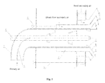
- the dense phase swirl pulverized coal burner of the invention (hereinafter referred to as the burner) comprises a primary air channel 1, a direct flow secondary air channel 2 arranged around outer wall of a nozzle of the primary air channel 1, and a swirl secondary air channel 3 arranged around outer wall of a nozzle of the direct flow secondary air channel 2.
- the direct flow secondary air channel 2 and the swirl secondary air channel 3 distribute air in a same big wind box.
- the primary air channel I is provided with the following parts communicating successively: an elbow section as a pulverized coal inlet, a straight tube section arranged horizontally and a primary air nozzle.
- An oil gun casing 4 is arranged on a central axis of the straight tube section of the primary air channel 1, and a torch oil gun of the burner is arranged inside the oil gun casing 4.
- the elbow section of the primary air channel 1 is provided with a pulverized coal flow equalizing plate 5 arranged around the central axis of the elbow section and divided into interior and exterior two-layer air channels near and far from a turning center in the elbow section; one end of the pulverized coal flow equalizing plate 5 is arranged on an inlet of the elbow section, and the other end thereof extends to an outlet of the elbow section, i.e. the position where the elbow section communicates with the straight tube section.
- each level of pulverized coal concentration rings 6 is a cone flaring structure arranged around outer edge of the oil gun casing 4, a cone flaring opening thereof faces the nozzle, and cone flaring angles ⁇ of the pulverized coal concentration rings is within the range of 10° to 25°; and size of the pulverized coal concentration rings 6 is enlarged by levels.
- the nozzle of the primary air channel 1 is provided with multiple guide vanes 7 arranged uniformly and circumferentially around inner wall thereof (10 to 20 vanes); an included angle between each of the guide vanes 7 and axial direction of the primary air channel 1 is 10° to 30°, and radial height of the guide vanes along the primary air channel I is 0.05 to 0.1 time diameter of the primary air channel 1.
- the multiple guide vanes 7 are arranged on an area at the periphery of the channel where the dense phase pulverized coal flows; dense phase flow is disturbed to eject at a certain swirl angle before being ejected into the furnace, and the dilute phase pulverized coal air flow at the center is still ejected into the furnace along the axis of the channel by direct flow.
- Flow expanding cone structures facing one end of the furnace and corresponding to serial number 8, 9 and 10 in Figure 1 are arranged on outer walls of the nozzles of the primary air channel 1, the direct flow secondary air channel 2 and the swirl secondary air channel 3 respectively, thus delaying mixing time of the secondary air and the primary air under the action of cone flaring. Based on reasonable control of the cone flaring angles, an oxygen-deficient atmosphere can be formed in the primary air during initial ignition, which allows sufficient reduction of early nitric oxides.
- the preferred cone flaring angles ⁇ 1, ⁇ 2 and ⁇ 3 corresponding to the flow expanding cone structures 8, 9 and 10 are not more than 45° respectively.
- the direct flow secondary air channel 2 and the swirl secondary air channel 3 are provided with regulating devices 11 and 12 respectively for controlling air flow and swirl air strength to control mixing time of the secondary air and the primary air.
- regulating devices 11 and 12 respectively for controlling air flow and swirl air strength to control mixing time of the secondary air and the primary air.
- Appropriate mixing of the primary air and the secondary air can allow water cooled walls of the nozzles to be in an oxidizing atmosphere for a long time, effectively preventing clogging and high temperature corrosion of the water cooled wall of the burner zone.
- the dilute phase pulverized coal air flow at the center of the primary air nozzle is directly ejected into the furnace along the axis of the channel without disturbed flow, which can keep rigidity of the primary air and ensure that the primary air is ejected into a certainly deep position in the furnace.
- the pulverized coal air flow is strongly mixed to ensure subsequent mixing and combustion of the pulverized coal air flow, reduce nitric oxides in the burner during initial oxygen-deficient combustion and achieve the purpose of efficient burning-out of the pulverized coal.
- the invention can be strongly adaptable to various types of coal.
- the cone flaring angle and grading arrangement of the pulverized coal concentration rings 6 can be designed to control dense and dilute separation degree of the pulverized coal; radial height of the guide vanes 7, and size of the included angle between the guide vanes 7 and the axial direction can be designed to control disturbed flow of the dense phase pulverized coal; and the flow expanding cone structure 8 of the primary air nozzle can be used to control the size of the high temperature backflow area.
- swirl intensity of the secondary air can be regulated by the regulating devices 11, 12 to adapt to ignition and stable combustion requirements of different types of coal.
- the invention is characterized by simple structure, good wear resistance, strong ignition and stable combustion, good coal adaptability, high efficiency and low nitric oxide emission.
Applications Claiming Priority (2)
| Application Number | Priority Date | Filing Date | Title |
|---|---|---|---|
| CN201180139317 | 2011-05-27 | ||
| PCT/CN2012/071214 WO2012163107A1 (fr) | 2011-05-27 | 2012-02-16 | Brûleur à charbon pulvérisé à tourbillon à phase dense |
Publications (2)
| Publication Number | Publication Date |
|---|---|
| EP2597367A1 true EP2597367A1 (fr) | 2013-05-29 |
| EP2597367A4 EP2597367A4 (fr) | 2014-10-29 |
Family
ID=48141702
Family Applications (1)
| Application Number | Title | Priority Date | Filing Date |
|---|---|---|---|
| EP12792844.8A Withdrawn EP2597367A4 (fr) | 2011-05-27 | 2012-02-16 | Brûleur à charbon pulvérisé à tourbillon à phase dense |
Country Status (2)
| Country | Link |
|---|---|
| US (1) | US20130112120A1 (fr) |
| EP (1) | EP2597367A4 (fr) |
Cited By (5)
| Publication number | Priority date | Publication date | Assignee | Title |
|---|---|---|---|---|
| CN103672885A (zh) * | 2013-12-31 | 2014-03-26 | 北京国电龙高科环境工程技术有限公司 | 一种一次风喷嘴内部偏转的垂直浓淡直流煤粉燃烧装置 |
| CN103759259A (zh) * | 2014-01-13 | 2014-04-30 | 徐州燃控科技股份有限公司 | 强化分级低NOx煤粉燃烧器 |
| CN106051758A (zh) * | 2016-07-14 | 2016-10-26 | 无锡华光锅炉股份有限公司 | 一种周界风布置结构 |
| CN106642096A (zh) * | 2016-12-08 | 2017-05-10 | 哈尔滨工业大学 | 一种燃料分级局部富氧旋流煤粉燃烧器 |
| CN110848672A (zh) * | 2018-08-20 | 2020-02-28 | 三菱日立电力系统株式会社 | 固体燃料喷烧器 |
Families Citing this family (27)
| Publication number | Priority date | Publication date | Assignee | Title |
|---|---|---|---|---|
| CN104197326A (zh) * | 2014-07-15 | 2014-12-10 | 北京神雾环境能源科技集团股份有限公司 | 一种新型旋流煤粉燃烧器 |
| JP6188658B2 (ja) * | 2014-09-24 | 2017-08-30 | 三菱重工業株式会社 | 燃焼バーナ及びボイラ |
| CN105485675B (zh) * | 2015-12-28 | 2018-08-31 | 西安热工研究院有限公司 | 一种带有防磨风的旋流燃烧器 |
| CN105953225B (zh) * | 2016-06-23 | 2023-12-22 | 王鹏钊 | 一种煤粉燃烧器 |
| CN106224949B (zh) * | 2016-08-24 | 2018-04-24 | 东南大学 | 一种非同轴水平浓淡低NOx直流煤粉燃烧器 |
| CN106765076B (zh) * | 2017-01-17 | 2023-06-16 | 郑州轻工业大学 | 一种可调控的旋流煤粉燃烧器 |
| CN107339689A (zh) * | 2017-07-01 | 2017-11-10 | 重庆富燃科技股份有限公司 | 一种调节内燃烧燃烧器空气余量系数降低氮氧化物的装置及方法 |
| CN107606613A (zh) * | 2017-09-27 | 2018-01-19 | 西安交通大学 | 燃气空气精确分级内置烟气再循环的低氮旋流燃气燃烧器 |
| CN108180468A (zh) * | 2018-02-10 | 2018-06-19 | 西安交通大学 | 一种跨负荷调节的多级配风适时给氧解耦燃烧器 |
| CN108339655B (zh) * | 2018-02-23 | 2023-06-30 | 北京蓝爱迪电力技术有限公司 | 一种中速磨煤机旋转喷嘴结构 |
| CN108302525B (zh) * | 2018-03-09 | 2023-09-22 | 山西大学 | 一种通流面积可调直流煤粉燃烧器 |
| CN108361692A (zh) * | 2018-04-24 | 2018-08-03 | 徐州科能燃烧控制科技有限公司 | 一种工业锅炉煤粉燃烧器 |
| CN108826285B (zh) * | 2018-06-01 | 2023-11-03 | 山西瓦特网联环能科技有限公司 | 大调节比煤粉燃烧器 |
| CN108592014A (zh) * | 2018-06-22 | 2018-09-28 | 江西中船航海仪器有限公司 | 一种多级燃气与多级空气混合系统 |
| CN109099425B (zh) * | 2018-10-22 | 2022-06-28 | 北京泷涛环境科技有限公司 | 一种烟气内循环超低氮燃烧器 |
| CN109708106B (zh) * | 2018-12-19 | 2023-10-24 | 东方电气集团东方锅炉股份有限公司 | 一种直流煤粉燃烧器 |
| CN109737393B (zh) * | 2019-02-19 | 2024-02-27 | 沈阳环境科学研究院 | 大煤粉浓缩比推迟混合式旋流煤粉燃烧器 |
| CN112833391A (zh) * | 2019-11-25 | 2021-05-25 | 中国科学院工程热物理研究所 | 燃料喷口、预热燃烧器,固体燃料燃烧系统及其燃烧控制方法 |
| CN110887037A (zh) * | 2019-12-19 | 2020-03-17 | 沈阳环境科学研究院 | 一种加强煤粉气化的低氮燃烧装置 |
| CN111023148A (zh) * | 2020-01-14 | 2020-04-17 | 薛芳 | 可调螺旋式多级无油煤粉点火器 |
| CN111237796A (zh) * | 2020-02-28 | 2020-06-05 | 沈阳环境科学研究院 | 一种低能耗高效煤粉浓缩器 |
| CN111425850B (zh) * | 2020-04-14 | 2022-02-08 | 哈尔滨锅炉厂有限责任公司 | 一种可整体上下左右摆动旋流燃尽风燃烧器 |
| CN112228868B (zh) * | 2020-08-20 | 2023-04-28 | 陕西商洛发电有限公司 | 一种同时调节一次风和侧边风流速的水平浓淡煤粉燃烧器 |
| CN112628728B (zh) * | 2020-12-22 | 2023-05-12 | 江苏羚羊机械有限公司 | 一种新型回转窑燃烧器可调旋流装置 |
| CN112902173B (zh) * | 2021-02-07 | 2022-03-04 | 哈尔滨工业大学 | 一种采用高温一二次风燃尽固废的装置 |
| CN113308258A (zh) * | 2021-06-21 | 2021-08-27 | 河南省科学院 | 一种生物质烘焙热解系统 |
| CN113654045A (zh) * | 2021-08-12 | 2021-11-16 | 福建华夏蓝天科技有限公司 | 内外双旋流分级低氮气体燃烧器 |
Citations (6)
| Publication number | Priority date | Publication date | Assignee | Title |
|---|---|---|---|---|
| US2380463A (en) * | 1942-06-23 | 1945-07-31 | Babcock & Wilcox Co | Fluent fuel burner |
| US3256842A (en) * | 1963-04-02 | 1966-06-21 | Babcock & Wilcox Ltd | Multiple fuel burner |
| US4951581A (en) * | 1989-06-21 | 1990-08-28 | Aptec, Inc. | Combined oil gun and coal guide for power plant boilers |
| CN1439842A (zh) * | 2003-02-28 | 2003-09-03 | 哈尔滨工业大学 | 一种中心给粉旋流煤粉燃烧器 |
| CN101832550A (zh) * | 2010-06-18 | 2010-09-15 | 上海交通大学 | 基于多级煤粉浓缩的旋流煤粉燃烧器 |
| CN102062396A (zh) * | 2010-10-13 | 2011-05-18 | 西安交通大学 | 一种复合浓淡三调风低NOx旋流煤粉燃烧器 |
Family Cites Families (4)
| Publication number | Priority date | Publication date | Assignee | Title |
|---|---|---|---|---|
| GB9402553D0 (en) * | 1994-02-10 | 1994-04-13 | Rolls Royce Power Eng | Burner for the combustion of fuel |
| CA2151308C (fr) * | 1994-06-17 | 1999-06-08 | Hideaki Ohta | Bruleur a combustible pulverise |
| US5697306A (en) * | 1997-01-28 | 1997-12-16 | The Babcock & Wilcox Company | Low NOx short flame burner with control of primary air/fuel ratio for NOx reduction |
| WO2009009945A1 (fr) * | 2007-07-18 | 2009-01-22 | Harbin Institute Of Technology | Brûleur de charbon pulvérisé à turbulence à faible nox |
-
2012
- 2012-02-16 US US13/808,119 patent/US20130112120A1/en not_active Abandoned
- 2012-02-16 EP EP12792844.8A patent/EP2597367A4/fr not_active Withdrawn
Patent Citations (6)
| Publication number | Priority date | Publication date | Assignee | Title |
|---|---|---|---|---|
| US2380463A (en) * | 1942-06-23 | 1945-07-31 | Babcock & Wilcox Co | Fluent fuel burner |
| US3256842A (en) * | 1963-04-02 | 1966-06-21 | Babcock & Wilcox Ltd | Multiple fuel burner |
| US4951581A (en) * | 1989-06-21 | 1990-08-28 | Aptec, Inc. | Combined oil gun and coal guide for power plant boilers |
| CN1439842A (zh) * | 2003-02-28 | 2003-09-03 | 哈尔滨工业大学 | 一种中心给粉旋流煤粉燃烧器 |
| CN101832550A (zh) * | 2010-06-18 | 2010-09-15 | 上海交通大学 | 基于多级煤粉浓缩的旋流煤粉燃烧器 |
| CN102062396A (zh) * | 2010-10-13 | 2011-05-18 | 西安交通大学 | 一种复合浓淡三调风低NOx旋流煤粉燃烧器 |
Non-Patent Citations (1)
| Title |
|---|
| See also references of WO2012163107A1 * |
Cited By (6)
| Publication number | Priority date | Publication date | Assignee | Title |
|---|---|---|---|---|
| CN103672885A (zh) * | 2013-12-31 | 2014-03-26 | 北京国电龙高科环境工程技术有限公司 | 一种一次风喷嘴内部偏转的垂直浓淡直流煤粉燃烧装置 |
| CN103759259A (zh) * | 2014-01-13 | 2014-04-30 | 徐州燃控科技股份有限公司 | 强化分级低NOx煤粉燃烧器 |
| CN103759259B (zh) * | 2014-01-13 | 2016-06-15 | 徐州科融环境资源股份有限公司 | 强化分级低NOx煤粉燃烧器 |
| CN106051758A (zh) * | 2016-07-14 | 2016-10-26 | 无锡华光锅炉股份有限公司 | 一种周界风布置结构 |
| CN106642096A (zh) * | 2016-12-08 | 2017-05-10 | 哈尔滨工业大学 | 一种燃料分级局部富氧旋流煤粉燃烧器 |
| CN110848672A (zh) * | 2018-08-20 | 2020-02-28 | 三菱日立电力系统株式会社 | 固体燃料喷烧器 |
Also Published As
| Publication number | Publication date |
|---|---|
| US20130112120A1 (en) | 2013-05-09 |
| EP2597367A4 (fr) | 2014-10-29 |
Similar Documents
| Publication | Publication Date | Title |
|---|---|---|
| EP2597367A1 (fr) | Brûleur à charbon pulvérisé à tourbillon à phase dense | |
| CN107559827B (zh) | 一种超低氮燃气燃烧器 | |
| WO2012163107A1 (fr) | Brûleur à charbon pulvérisé à tourbillon à phase dense | |
| CN102235666B (zh) | 一种煤粉燃烧器及包括该煤粉燃烧器的煤粉锅炉 | |
| US20200224872A1 (en) | Burners and methods for use thereof | |
| CN104791775A (zh) | 燃烧器底置的立式煤粉锅炉 | |
| CN107062226B (zh) | 一种高温烟气大回流低氮燃烧器 | |
| CN102537951B (zh) | 中心扩散式微油点火燃烧器 | |
| US9841189B2 (en) | Lean premix burner having center gas nozzle | |
| CN104421933A (zh) | 适用于燃烧器的一次风管、燃烧器和固体燃料锅炉 | |
| CN101718432B (zh) | 旋流喷射式煤粉燃烧器 | |
| CN104296142B (zh) | 燃气无焰纯氧燃烧器 | |
| AU2011332718B2 (en) | Pulverized fuel fired boiler equipment | |
| CN109099425B (zh) | 一种烟气内循环超低氮燃烧器 | |
| CN109959005B (zh) | 一种用于燃气灶的燃烧器 | |
| CN202024323U (zh) | 粉体燃料燃烧器 | |
| CN104566460A (zh) | 一种具有突扩通道的燃料空气混合器 | |
| JP2010054142A (ja) | 燃焼器 | |
| CN203731402U (zh) | 一种用于煤粉工业锅炉的双调风煤粉燃烧器 | |
| CN203703972U (zh) | 一种燃烧器以及燃烧炉 | |
| CN207196495U (zh) | 太极旋流扩散式低氮氧化物排放燃烧头及其并联结构 | |
| JP7075287B2 (ja) | 油焚きバーナおよび多管式貫流ボイラ | |
| CN108758629B (zh) | 低氮氧化合物燃气燃烧器 | |
| CN102620295B (zh) | 一种工业用径向浓缩双调风旋流煤粉与燃气混合燃烧器 | |
| JP6732960B2 (ja) | 燃料を燃焼させる方法及びボイラー |
Legal Events
| Date | Code | Title | Description |
|---|---|---|---|
| PUAI | Public reference made under article 153(3) epc to a published international application that has entered the european phase |
Free format text: ORIGINAL CODE: 0009012 |
|
| 17P | Request for examination filed |
Effective date: 20130225 |
|
| AK | Designated contracting states |
Kind code of ref document: A1 Designated state(s): AL AT BE BG CH CY CZ DE DK EE ES FI FR GB GR HR HU IE IS IT LI LT LU LV MC MK MT NL NO PL PT RO RS SE SI SK SM TR |
|
| DAX | Request for extension of the european patent (deleted) | ||
| A4 | Supplementary search report drawn up and despatched |
Effective date: 20140925 |
|
| RIC1 | Information provided on ipc code assigned before grant |
Ipc: F23D 1/02 20060101AFI20140919BHEP |
|
| STAA | Information on the status of an ep patent application or granted ep patent |
Free format text: STATUS: THE APPLICATION IS DEEMED TO BE WITHDRAWN |
|
| 18D | Application deemed to be withdrawn |
Effective date: 20180901 |