EP2597359B1 - Projection light module for a motor vehicle headlamp - Google Patents
Projection light module for a motor vehicle headlamp Download PDFInfo
- Publication number
- EP2597359B1 EP2597359B1 EP12192572.1A EP12192572A EP2597359B1 EP 2597359 B1 EP2597359 B1 EP 2597359B1 EP 12192572 A EP12192572 A EP 12192572A EP 2597359 B1 EP2597359 B1 EP 2597359B1
- Authority
- EP
- European Patent Office
- Prior art keywords
- guide
- elements
- light module
- projection light
- guide elements
- Prior art date
- Legal status (The legal status is an assumption and is not a legal conclusion. Google has not performed a legal analysis and makes no representation as to the accuracy of the status listed.)
- Active
Links
Images


Classifications
-
- G—PHYSICS
- G02—OPTICS
- G02B—OPTICAL ELEMENTS, SYSTEMS OR APPARATUS
- G02B7/00—Mountings, adjusting means, or light-tight connections, for optical elements
- G02B7/02—Mountings, adjusting means, or light-tight connections, for optical elements for lenses
- G02B7/023—Mountings, adjusting means, or light-tight connections, for optical elements for lenses permitting adjustment
-
- F—MECHANICAL ENGINEERING; LIGHTING; HEATING; WEAPONS; BLASTING
- F21—LIGHTING
- F21S—NON-PORTABLE LIGHTING DEVICES; SYSTEMS THEREOF; VEHICLE LIGHTING DEVICES SPECIALLY ADAPTED FOR VEHICLE EXTERIORS
- F21S41/00—Illuminating devices specially adapted for vehicle exteriors, e.g. headlamps
- F21S41/10—Illuminating devices specially adapted for vehicle exteriors, e.g. headlamps characterised by the light source
- F21S41/14—Illuminating devices specially adapted for vehicle exteriors, e.g. headlamps characterised by the light source characterised by the type of light source
- F21S41/141—Light emitting diodes [LED]
- F21S41/147—Light emitting diodes [LED] the main emission direction of the LED being angled to the optical axis of the illuminating device
- F21S41/148—Light emitting diodes [LED] the main emission direction of the LED being angled to the optical axis of the illuminating device the main emission direction of the LED being perpendicular to the optical axis
-
- F—MECHANICAL ENGINEERING; LIGHTING; HEATING; WEAPONS; BLASTING
- F21—LIGHTING
- F21S—NON-PORTABLE LIGHTING DEVICES; SYSTEMS THEREOF; VEHICLE LIGHTING DEVICES SPECIALLY ADAPTED FOR VEHICLE EXTERIORS
- F21S41/00—Illuminating devices specially adapted for vehicle exteriors, e.g. headlamps
- F21S41/20—Illuminating devices specially adapted for vehicle exteriors, e.g. headlamps characterised by refractors, transparent cover plates, light guides or filters
- F21S41/25—Projection lenses
- F21S41/255—Lenses with a front view of circular or truncated circular outline
-
- F—MECHANICAL ENGINEERING; LIGHTING; HEATING; WEAPONS; BLASTING
- F21—LIGHTING
- F21S—NON-PORTABLE LIGHTING DEVICES; SYSTEMS THEREOF; VEHICLE LIGHTING DEVICES SPECIALLY ADAPTED FOR VEHICLE EXTERIORS
- F21S41/00—Illuminating devices specially adapted for vehicle exteriors, e.g. headlamps
- F21S41/20—Illuminating devices specially adapted for vehicle exteriors, e.g. headlamps characterised by refractors, transparent cover plates, light guides or filters
- F21S41/29—Attachment thereof
- F21S41/295—Attachment thereof specially adapted to projection lenses
-
- F—MECHANICAL ENGINEERING; LIGHTING; HEATING; WEAPONS; BLASTING
- F21—LIGHTING
- F21S—NON-PORTABLE LIGHTING DEVICES; SYSTEMS THEREOF; VEHICLE LIGHTING DEVICES SPECIALLY ADAPTED FOR VEHICLE EXTERIORS
- F21S41/00—Illuminating devices specially adapted for vehicle exteriors, e.g. headlamps
- F21S41/60—Illuminating devices specially adapted for vehicle exteriors, e.g. headlamps characterised by a variable light distribution
- F21S41/68—Illuminating devices specially adapted for vehicle exteriors, e.g. headlamps characterised by a variable light distribution by acting on screens
- F21S41/683—Illuminating devices specially adapted for vehicle exteriors, e.g. headlamps characterised by a variable light distribution by acting on screens by moving screens
- F21S41/698—Shaft-shaped screens rotating along its longitudinal axis
-
- G—PHYSICS
- G02—OPTICS
- G02B—OPTICAL ELEMENTS, SYSTEMS OR APPARATUS
- G02B19/00—Condensers, e.g. light collectors or similar non-imaging optics
- G02B19/0004—Condensers, e.g. light collectors or similar non-imaging optics characterised by the optical means employed
- G02B19/0028—Condensers, e.g. light collectors or similar non-imaging optics characterised by the optical means employed refractive and reflective surfaces, e.g. non-imaging catadioptric systems
-
- G—PHYSICS
- G02—OPTICS
- G02B—OPTICAL ELEMENTS, SYSTEMS OR APPARATUS
- G02B19/00—Condensers, e.g. light collectors or similar non-imaging optics
- G02B19/0033—Condensers, e.g. light collectors or similar non-imaging optics characterised by the use
- G02B19/0047—Condensers, e.g. light collectors or similar non-imaging optics characterised by the use for use with a light source
- G02B19/0061—Condensers, e.g. light collectors or similar non-imaging optics characterised by the use for use with a light source the light source comprising a LED
Definitions
- the present invention relates to a projection light module for a motor vehicle headlight according to the preamble of claim 1.
- a projection light module has a complex light source with a carrier element and a lens holder, with which a secondary optics of the projection light module is attached to the carrier element
- Such a projection Light module is for example from the DE 10 2009 032 456 A1 or EP 0 985 871 A2 known.
- a complex light source here means the structural unit comprising a light source, a primary optic, a diaphragm and the support element which holds these elements together relative to one another.
- the primary optics focuses light from the light source into a first light distribution that is located inside the light source Projection light module is located.
- the first light distribution is limited by an edge of an aperture projecting into the first light distribution.
- the projection light module on a secondary optics, which is focused on the first light distribution and which images the first light distribution as a second light distribution in the apron in front of the vehicle headlight.
- the carrier element serves as the structural basis of the complex light source and the entire projection light module.
- a carrier element can either be a separate component or it can be realized for example by a correspondingly stable, serving as a primary reflector. This is in the aforementioned DE 10 2009 032 456 A1 the case.
- a projection lens serving as secondary optics is generally connected to the carrier element via a lens holder.
- the lens holder also serves to produce a predetermined distance of the secondary optics from the diaphragm edge. This distance usually corresponds to the focal length of the projection lens.
- the aperture edge is projected as a cut-off in height and reversed in the apron in front of the projection light module.
- the light-dark border thus separates a bright area from a dark area of the light distribution of the projection light module.
- the distance of the lens from the diaphragm edge and the angular position of the lens relative to the optical axis influence the quality of the imaging of the diaphragm edge as a light-dark boundary of the light distribution.
- a fringe of color may result in the second light distribution at the cut-off line.
- a color fringe is understood to mean the effect that a narrow, rather reddish, or rather bluish transition region is visible at the light-dark boundary.
- a projection lens having a focal length. Strictly speaking, one has to speak of a medium focal length, since the focal length is wavelength-dependent and in particular smaller for blue light than for red Light is. Blue light is therefore more strongly refracted than red light.
- An optical system for example the primary optics of the projection light module, focuses white light into the first light distribution, which is located at a distance of the average focal length of the secondary optics before the secondary optics. Divergent white light then emanates from the first light distribution and falls onto a light entry surface of the lens. A diaphragm is pushed into the beam path transversely to an optical axis of the lens so far that the optical axis touches the diaphragm edge in a grazing manner.
- a reddish-colored transition region results, that is, a color fringe dominated by a red color impression. If, on the other hand, the aperture lies in the light propagation direction before the first light distribution, ie outside the medium focal length, a bluish transition region results, that is to say a bluish fringe of color.
- the coloration and the intensity of the disturbing color fringes thus depend in particular on the position of the aperture in relation to the focal length of the projection lens. In the case of an incorrect position, unwanted color-intensive color fringes in particular can occur at the cut-off line.
- the lens holder is made of sheet metal and has a receiving ring for receiving the Lens and at least three projecting from the receiving ring struts, which serve to produce the required for the imaging of the diaphragm edge distance between the diaphragm edge and the lens.
- Each strut has a tab which serves for fastening the strut to the support element of the complex light source, there in particular to the reflector.
- the receiving ring is adapted to be connected to a lens holding ring which holds the lens in the axial direction in the receiving ring.
- the lens is inserted into the receiving ring.
- the exact position of the lens in the pickup ring is adjusted for the purpose of color fringe correction, and the lens is fixed in the set position.
- the lens holding ring is slid over the edge of the lens. In the end position of the lens holding ring this is pressed radially inward in the region of the underlying recesses in the receiving ring and thus positively and positively connected to the receiving ring. As a result, the lens is held at a fixed distance from the diaphragm between the receiving ring and the lens holder ring pressed therewith.
- the projection light modules have to meet more and more demands on their appearance beyond their lighting function.
- the aim is to be able to use lens holder made of plastic, as resulting from the use of plastic design degrees of freedom, at least at the same Costs with metallic lens holders can not be realized.
- the object of the invention in the specification of a projection light module of the type mentioned, which allows the use of plastic as a material for the lens holder.
- the projection light module must allow a color fringe correction by adjusting the distance between the lens and the diaphragm edge and, for design reasons, it should also permit the use of lenses which do not have a circular circumference.
- the present invention differs from the aforementioned prior art in that the lens holder has first guide elements and the carrier element second guide elements, and in that the projection light module has locking elements which are arranged and arranged both in the first guide elements and in to engage the second guide elements and a mutual displacement block the guide elements, wherein the first guide elements and the second guide elements interlock and adapted to each other are adapted to allow a release against each other with released locking elements, which is parallel to an optical axis of the projection light module.
- the interval between the lens and the carrier element and thus ultimately between the lens and the diaphragm edge is adjusted by the interlocking first guide elements and second guide elements, which allow a displacement parallel to the optical axis with dissolved or not detected locking elements to a color fringe correction to enable.
- the locking elements By means of the locking elements, the displacement can then be blocked so that a color correction carried out once is maintained.
- the locking elements are screws.
- the locking elements are pins which have at least one cutting edge which extends parallel to the longitudinal axis of such a pin and protrudes laterally from the core diameter of such a pin.
- the locking elements are guided in holes in the second guide elements, which are aligned transversely to the optical axis and arranged so that the first guide elements and the second guide elements are braced against each other during insertion or insertion of the locking elements.
- the bore is arranged relative to a recess in the second guide member so that thread flanks or cutting edges of a guided by the bore locking element protrude into the recess in the second guide element, so that thread flanks or cutting edges of the locking element when screwing or pushing into the hole , which is located in the second guide element, cut into a first guide element, which is located in the recess of the second guide element.
- the diameter of the bore corresponds to a core diameter or an outer diameter of the locking element.
- the bore is located relative to the recess so that a boundary surface of the recess touches or breaks through the cylinder jacket surface of the bore.
- the cross section of the recess in the second guide element and the complementary cross section of the first guide element in the plane perpendicular to the displacement direction has a shape in which the respective diameter of the cross section in the direction of the longitudinal axis of the screw with increasing radial distance the screw is reduced.
- a further preferred embodiment is characterized in that the second guide elements are arranged on the support element and aligned so that the diameter of a cross section having a second guide element, in one direction reduced, which is opposite to the direction in which the diameter of the cross section of an adjacent second guide member decreases.
- At least the first guide elements are made of plastic.
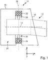
- FIG. 1 In contrast to a luminaire, a motor vehicle headlamp is a lighting device which is set up to illuminate the travel path of a motor vehicle in such a way that a driver of the motor vehicle can recognize obstacles lying in the roadway in good time.
- the headlamp emits a directed light beam 12, which generates a predetermined, legally required light distribution in the run-up to the pork launcher 10
- FIG. 1 shows in particular a highly schematic cross section of a headlamp 10, wherein the cutting plane is parallel to an optical axis 14 of the headlamp 10.
- a coordinate system is shown with which the different directions of view used in the figures can be related to each other. It is a firmly connected to the headlight 10 Coordinate system.
- the x-direction is parallel to the longitudinal axis of the vehicle and points forwards, while the y-direction is parallel to a transverse axis and the z-direction is parallel to a vertical axis of the vehicle.
- the headlight 10 has a housing 16 with a light exit opening.
- the light exit opening is covered by a transparent cover 18.
- a projection light module 20 is arranged inside the housing 16.
- the projection light module 20 has an outer frame 22, which is mounted pivotably about a first axis 24 in the housing 16.
- the first axis 24 is transverse to the optical axis 14, which otherwise corresponds to a Hauptlichtabstrahlraum.
- the first axis 24 is at a proper use transverse to a vertical axis of the motor vehicle and thus in a vehicle on a flat surface, generally parallel to the horizon.
- the pivoting about the first axis 24 allows a headlight range control, which is effected by detecting an inclination of the motor vehicle and the pivoting position of the projection light module 20 about the first axis 24 is automatically adjusted in response to the detected inclination that the emission direction of the light beam 12 is constant regardless of the inclination of the motor vehicle.
- a controlled change in the range as it increases in an upward panning. This is used in one embodiment for raising the light beam for a motorway light distribution.
- an assembly of the projection light module is pivotally suspended about a second axis 26.
- the second axis 26 is in a proper use in a motor vehicle substantially parallel to a vertical axis of the motor vehicle.
- the first axis 24 and the second axis 26 are preferably aligned at right angles to each other.
- the pivoting about the second axis 26 allows during operation of the motor vehicle, a pivoting of the light beam 12 to the right and left to better illuminate the road when cornering.
- the light beam 12 is pivoted to the inside of the curve, e.g. depending on a steering angle detected for this purpose.
- Fig. 1 shows each of the two bearings schematically as a pairing of a bearing pin and a bearing sleeve, wherein the bearing pin is in each case a part of the outer frame 22 mounted assembly.
- This arrangement may also be the other way round in one of the bearings or even in both bearings. You can also use different bearings.
- the basic mode of operation of the cornering light function and the drive used for a cornering light function are familiar to the person skilled in the art and need no further explanation here.
- Fig. 2 shows an embodiment of a tiltable projection light module 20 having features of the invention.
- a projection light module 20 according to the invention need not all of the in the Fig. 2 or even the in the Fig. 1 have shown features. In particular, it does not have to be pivotable about a first axis 24 for a headlight range control or about a second axis 26 for a cornering light function. However, it is essential that it is a projection light module, regardless of whether a cornering light function and / or a headlight range control is realized.
- a projection light module 20 has a secondary optics 32 which is adapted to an internal light distribution, which is in the interior of the projection light module 20 at a distance of a focal length of the secondary optics 32 in the light path in front of the secondary optics 32 from the light 12 of a light source 40 of the Projection light module 20 forms or is formed to project as an external light distribution in the apron of the headlamp 10.
- the secondary optics 32 is usually a projection lens 34.
- a lens is understood here to mean a transparent solid whose light-directing optical effect is limited to the refraction of light upon entry into the solid and upon exit from the solid.
- a lens can also serve a transparent solid, in which the light directing effect results, at least in part, by internal total reflection of the light at interfaces of the solid.
- secondary optics instead of the term “secondary optics", the more illustrative notion of a lens or projection lens 34 is generally used, but it should always be understood that the lens 34 could also be replaced by said alternative solid having the property of an internal lens Total reflection uses.
- the internal light distribution may be a light distribution as provided directly by a light source. It may be, for example, the light exit surface of a semiconductor light source, which in turn is composed of the light exit surfaces of one or more light-emitting diodes or laser diodes. For headlamps of motor vehicles white light-emitting LEDs are used, each having a single square or rectangular light exit surface with edge lengths between about 0.5 mm and 2 mm.
- the inner light distribution is generated from light that is focused by a primary optics on a point or a small area within the projection light module, which is at a distance of a focal length of the projection lens 34 in the light path in front of the projection lens 34.
- Such a focusing takes place in the subject matter of Fig. 2 by a primary optics 36 in the form of a reflector 38, which is adapted to focus from a first focus of the reflector 38 outgoing light into a second focus of the reflector 38.
- a primary optics 36 in the form of a reflector 38, which is adapted to focus from a first focus of the reflector 38 outgoing light into a second focus of the reflector 38.
- this is the case with an ellipsoid reflector in which the light source 40 is seated in the one focal point.
- the projection lens will then focused on the other, second focus of the reflector 38 arranged.
- Deviating from the purely elliptical shape but other forms are common, in which the reflector 38 is shaped so that it generates an internal light distribution with a desired shape. In one embodiment, this is achieved by so-called free-form reflectors, the shape of which is calculated and produced in accordance with the calculations so that predetermined surface elements of the reflector 38 reflect incident light just in such a way that the desired light distribution results.
- a light-refracting optic such as a lens or a light-refractive optic made of transparent material that directs internal total reflections to generate the internal light distribution.
- An optic which generates the inner light distribution is also referred to here as the primary optic 36.
- An aperture 42 is disposed in the focal area of the primary optics 36 and the secondary optics 32 and serves to create a desired shape of the internal light distribution by shading. For example, a bright-dark boundary of the inner light distribution created by the stop 42 is projected into the outer light distribution to achieve, for example, a low-beam distribution.
- the diaphragm 42 is in a preferred embodiment, a diaphragm roller with a surface which deviates from a pure cylindrical shape and depending on the angular position of the diaphragm roller differently shaped diaphragm edges and aperture radii R, r provides. By changing the Angular position can thus vary the shape and position of a light-dark boundary and / or produce a light distribution without pronounced cut-off.
- the quality of the external light distribution depends in particular on the distance 58 of the secondary optics 32 from the internal light distribution, as has already been explained in the introduction.
- the distance 58 corresponds approximately to a mean focal length of the secondary optics.
- the FIG. 2 shows in particular a projection light module 20 for a motor vehicle headlight 10 with a complex light source 44.
- the complex light source 44 has a support member 46 to which a lens holder 48 can be attached.
- the carrier element 46 is preferably a composite part of a first carrier structure 50 made of metal and a second carrier structure 52 made of plastic.
- the composite part is produced, for example, by placing a part of the first carrier structure 50 in an injection mold, with which the second carrier structure 52 is produced.
- the second carrier structure 52 is produced, the inserted part of the first carrier structure 50 is then embedded in the material of the second carrier structure 52 so that the composite part results when the material of the second carrier structure 52 hardens.
- the metallic first support structure 50 has a high heat capacity and thermal conductivity, which is favorable for effective cooling of a semiconductor light source used as a light source 40.
- the semiconductor light source is preferably mounted in good thermal contact on the first support structure 50.
- the preferred second plastic support structure 52 has the advantage that complex shapes, the attachment of the aperture 42, required for an adjustable aperture 42 aperture drive, the connection of the drive an optional curve light function, the associated storage and in particular the attachment structures for the secondary optics 32 by a plastic injection molded part as a lens holder 48 can be realized comparatively simple and inexpensive.
- the lens holder 48 has first guide elements 54, and the carrier element 46 has second guide elements 56.
- the first guide elements 54 and the second guide elements 56 engage with each other.
- the first guide elements 54 and the second guide elements 56 are adapted to each other to allow a mutual displacement, which is parallel to the optical axis 14 of the projection light module 20. In the other two Spatial directions, on the other hand, do not allow any relative movement between the lens holder 48 and the carrier element 46.
- the displaceability allows adjustment of the distance 58 between the projection lens 34 and the internal light distribution.
- the displaceability in particular allows the setting of a distance 58, are minimized in the disturbing color effects that occur at the light-dark boundary in the second light distribution.
- the projection light module 20 has locking elements 60 (cf. Fig. 3 ) on.
- the locking elements are preferably screws 62 (cf. Fig. 3 ).
- the screws 62 are preferably guided in holes 64 in the second guide elements 56, which are aligned transversely to the optical axis 14 and arranged so that the first guide elements 54 and the second guide elements 56 are braced against each other during insertion of the locking elements.
- the first guide elements 54 and the second guide elements 56 are therefore not braced against each other and are therefore parallel to the optical axis 14 against each other.
- the color fringe correction is performed.
- the distance 58 between the projection lens 34 and the inner light distribution is changed by moving the first guide elements 54 against the second guide elements 56 until the disturbing color fringes are minimal. Subsequently, this distance 58 is fixed by fixing the locking elements 60.
- At least the first guide elements 54 but preferably the first guide elements 54 and the second guide elements 56 made of plastic.
- the first guide elements 54 are preferably a cohesive part of the lens holder 48 and are generated together with this in an injection molding process.
- the locking members 60 are configured and arranged to engage both the first guide members 54 and the second guide members 56 and to block mutual displacement of the guide members 54 and 56.
- first guide elements 54 and the second guide elements 56 engage with each other, wherein they are adapted to each other to allow a release against each other with released locking elements 60, which takes place parallel to an optical axis of the projection light module.
- FIG. 3a shows a front view of a single first guide member 54
- the FIG. 3b shows a front view of a single second guide element.
- the viewing direction lies in the case of Fig. 3a in the main propagation direction of the light and in the case of the Fig. 3b opposite to the main propagation direction of the light.
- the directions of the FIGS. 1 and 2 corresponds to the line of sight at Fig. 3a the x direction and at Fig. 3b the negative x-direction.
- the second guide element 56 has a recess 66, the cross section of which represents a negative of the cross section 68 of the first guide element 54.
- the dimensions of the first guide element 54 in the drawing plane are just as much smaller than the clear width of the recess 66 in the second guide element 56, that the first guide element 54 in the recess 66 of the second guide member 56 perpendicular to the plane and thus parallel to the optical axis displaceable is and at the same time held by the walls 70 of the recess 66 in the second guide member 56 so that in the complementary to the optical axis spatial directions y, z no relative movement between the first guide member 54 and the second guide member 56 is possible.
- the possibilities of movement of the first guide element 54 relative to the second guide element 56 are identical to the possibilities of movement of the lens holder 48 relative to the carrier element 46.
- FIG. 3b also shows an embodiment of a locking member 60 which is adapted and arranged to engage as far in the first guide member 54 and in the second guide member 56 and to block a mutual displacement of the two guide elements 54, 56.
- the locking element 60 is a screw 62 which is arranged transversely to the direction of the possible displacement of the first guide element 54 relative to the second guide element 56.
- the screw 62 is held in a bore 64 in the second guide member 56.
- the bore 64 is arranged relative to the recess 66 in the second guide element 54 such that thread flanks 63 of the guided through the bore 64 and screwed into the bore 64 screw 62 project into the recess 66 in the second guide member 56.
- the diameter of the bore 64 preferably corresponds to the core diameter of the screw 62 or its outer diameter.
- the bore 64 is particularly arranged so that the thread flanks of the screw 62 when screwing into the bore 64, which is located in the second guide member 56, cut into a first guide member 54 which is located in the recess 66 of the second guide member 56.
- the first guide element 54 consists of plastic. It is also preferable that the screws are screws with a self-tapping thread.
- the first guide element 54 By screwing in the screw 62, the first guide element 54 is thus pressed against the inner longitudinal wall of the second guide element 56 opposite the screw longitudinal axis. By this pressure, a static friction force between the first guide member 54 and the second guide member 56 is generated. Due to the static friction force, the otherwise possible displacement between the first guide element 54 and the second guide element 56 when the locking element 60 is released is blocked by a frictional connection.
- a positive connection between the first guide member 54 and the screw 62 and thus a positive connection of the first guide member 54 with the second guide member 56 is generated.
- FIG. 4 shows a section through such a connection between the first guide member 54 and the second guide member 56 along the line IV-IV in FIG. 3, FIG. 4 thus clarifies in particular the situation in connection with the FIG. 3 described hole 64 which serves to receive and guide the screw 62 as a locking element 60.
- FIG. 4 shows, in particular, that the bore 64 is arranged in the second guide element 56 such that the screw 62 to be screwed in is guided through the bore 64.
- the hatched area of the screw 62 corresponds to the core of the screw 62, while the dashed and running around the core line marks the height of the thread flanks with which the screw 62 engages the first guide member 54 and the second guide member 64, wherein the Intervene here is a cutting.
- FIG. 5 shows a section through the subject of FIG. 4 along the line VI-VI.
- FIG. 5 illustrates in particular the position of the bore 64 relative to the recess 66.
- the bore 64 is preferably relative to the recess 66 so that a boundary surface of the recess touches the cylinder surface of the bore 64 or breaks.
- the bore 64 lies in particular relative to the recess 66 such that the screw 62 screwed into the bore exerts a force on the first guide element 54.
- the cross section of the recess 66 in the second guide element 56 and the complementary cross section of the first guide element 54 in the plane perpendicular to the displacement direction is preferably such that the respective diameter d of the cross section in the direction of the longitudinal axis of the screw with increasing radial distance from the screw 62 decreased.
- the first guide element 54 is centered in the second guide element 56.
- the cross section of the first guide element 54 and the second guide element 56 has a curved shape, in particular a semicircle, or a triangular shape. These cross-sectional shapes cause the desired centering.
- the screw is arranged so that its longitudinal axis in the FIG. 4 lies in the sectional plane shown in dashed lines. Screwing in the guided in the second guide member, for example by a screw screw then causes the screw tip presses the first guide member against the screw tip opposite the inner wall of the second guide member. Also by this configuration, a frictional connection is generated, which would block a further displacement of the first and second guide elements relative to each other. This solution is also considered inventive.
- the first guide element 54 that is to say the lens holder 48 associated guide element is preferably made of plastic and a cohesive component of the lens holder 48, as it is produced for example by an injection molding process.
- the plastic material has the advantage of greater freedom of design compared to a realization of the lens holder as a metallic part.
- plastic has the disadvantageous property of plastically deforming under the constant action of a force, which is also called a creeping process. This can relax a positive connection. In the described environment occur in driving large acceleration forces, especially when driving over a bad distance. In connection with the described creeping process, this could possibly give rise to a risk that the connection fixed between the first guide element 54 and the second guide element 56 after the color fringe correction loosens and thus leads to the occurrence of undesired fringing.
- connection results in particular by the combination of a frictional connection and a positive connection, ie by connecting the force exerted by the screw 62 transversely to its longitudinal axis pressing force with a cutting of thread flanks of the screw 62 in the plastic material of the first guide member 54.
- the by cutting caused positive connection is not affected by the described creep process, so that this solution ensures greater reliability of the connection and thus greater long-term stability of the color fringe correction once made.
- FIG. 6 shows a front view of the support member 46 with four second guide elements 56.
- the second guide elements 56 are arranged at four corners of the support member 46 and aligned so that the curvature (respectively the reduction of the cross section 66, each cross-section 66 of a second guide member 56th has, in adjacent second guide elements 56 each in opposite directions in space.
- the curvature is directed downwards and thus in the negative z direction
- the curvature of the second guide elements 56 adjacent to this second guide element 56 is in the upper right and lower left respectively in the positive z direction points upwards.
- this embodiment is a positional coding that allows a position-correct installation of an asymmetric secondary lens and excludes a non-position-correct installation.
- pins which, instead of a thread, have at least one cutting edge which runs parallel to the longitudinal axis of such a pin and protrudes laterally from the core diameter of such a pin.
- first guide elements realized as pins and the second guide elements realized as hollow guides can also be reversed, so that the guide elements realized as pins are components of the carrier element and the second guide elements realized as hollow guides are components of the lens holder.
Description
Die vorliegende Erfindung betrifft ein Projektions-Lichtmodul für einen Kraftfahrzeugscheinwerfer nach dem Oberbegriff des Anspruchs 1. Ein solches Projektions-Lichtmodul weist eine Komplexlichtquelle mit einem Trägerelement und einen Linsenhalter auf, mit dem eine Sekundäroptik des Projektions-Lichtmoduls an dem Trägerelement befestigt ist Ein solches Projektions-Lichtmodul ist zum Beispiel aus der
Dabei wird unter einer Komplexlichtquelle hier die bauliche Einheit aus einer Lichtquelle, einer Primäroptik, einer Blende sowie des diese Elemente relativ zueinander zusammenhaltenden Trägerelements verstanden.In this case, a complex light source here means the structural unit comprising a light source, a primary optic, a diaphragm and the support element which holds these elements together relative to one another.
Die Primäroptik fokussiert Licht der Lichtquelle in eine erste Lichtverteilung, die im Inneren des Projektionslichtmoduls liegt. Die erste Lichtverteilung wird durch eine in die erste Lichtverteilung hineinragende Kante einer Blende begrenzt.The primary optics focuses light from the light source into a first light distribution that is located inside the light source Projection light module is located. The first light distribution is limited by an edge of an aperture projecting into the first light distribution.
Darüber hinaus weist das Projektions-Lichtmodul eine Sekundäroptik auf, die auf die erste Lichtverteilung fokussiert ist und welche die erste Lichtverteilung als zweite Lichtverteilung in das Vorfeld vor dem Kraftfahrzeugscheinwerfer abbildet.In addition, the projection light module on a secondary optics, which is focused on the first light distribution and which images the first light distribution as a second light distribution in the apron in front of the vehicle headlight.
Das Trägerelement dient als strukturelle Basis der Komplexlichtquelle und des gesamten Projektions-Lichtmoduls. Ein solches Trägerelement kann entweder ein gesondertes Bauteil sein oder es kann zum Beispiel durch einen entsprechend stabilen, als Primäroptik dienenden Reflektor verwirklicht sein. Dies ist bei der eingangs genannten
An einem solchen Trägerelement sind die einzelnen genannten Elemente direkt oder indirekt befestigt. So ist zum Beispiel eine als Sekundäroptik dienende Projektionslinse in der Regel über einen Linsenhalter mit dem Trägerelement verbunden. Der Linsenhalter dient insbesondere auch dazu, einen vorgegebenen Abstand der Sekundäroptik von der Blendenkante herzustellen. Dieser Abstand entspricht in der Regel der Brennweite der Projektionslinse.On such a support element, the individual elements mentioned are attached directly or indirectly. Thus, for example, a projection lens serving as secondary optics is generally connected to the carrier element via a lens holder. In particular, the lens holder also serves to produce a predetermined distance of the secondary optics from the diaphragm edge. This distance usually corresponds to the focal length of the projection lens.
Da die Blendenkante in ihrer Abblendlichtstellung in der Nähe der Brennebene der Projektionslinse liegt, wird die Blendenkante als Hell-Dunkel-Grenze höhen- und seitenverkehrt in das Vorfeld vor das Projektions-Lichtmodul projiziert.Since the diaphragm edge in its Abblendlichtstellung located near the focal plane of the projection lens, the aperture edge is projected as a cut-off in height and reversed in the apron in front of the projection light module.
Die Hell-Dunkel-Grenze trennt also einen hellen Bereich von einem dunklen Bereich der Lichtverteilung des Projektions-Lichtmoduls ab. Der Abstand der Linse von der Blendenkante und die Winkellage der Linse relativ zur optischen Achse beeinflussen die Qualität der Abbildung der Blendenkante als Hell-Dunkelgrenze der Lichtverteilung.The light-dark border thus separates a bright area from a dark area of the light distribution of the projection light module. The distance of the lens from the diaphragm edge and the angular position of the lens relative to the optical axis influence the quality of the imaging of the diaphragm edge as a light-dark boundary of the light distribution.
Beim Durchgang von weißem Licht durch eine Linse werden Lichtanteile mit vergleichsweise größerer Wellenlänge (zum Beispiel rotes Licht) schwächer gebrochen als Lichtanteile mit vergleichsweise kürzerer Wellenlänge (zum Beispiel blaues Licht), was auch als chromatische Aberration bekannt ist. Die Ursache dafür ist eine Wellenlängenabhängigkeit der Brechzahl der Linse. Dies führt dazu, dass der Brennpunkt für blaues Licht näher an der Linse liegt als der Brennpunkt für rotes Licht. Letzteres ist auch als Farblängsfehler bekannt.When passing white light through a lens, light components of comparatively larger wavelength (for example, red light) are refracted weaker than lights of comparatively shorter wavelength (for example, blue light), which is also known as chromatic aberration. The reason for this is a wavelength dependence of the refractive index of the lens. As a result, the focus for blue light is closer to the lens than the focus for red light. The latter is also known as color longitudinal error.
Als Folge kann sich in der zweiten Lichtverteilung an der Hell-Dunkel-Grenze ein Farbsaum ergeben. Dabei wird unter einem Farbsaum der Effekt verstanden, dass an der Hell-Dunkel-Grenze ein schmaler eher rötlich oder eher bläulich gefärbter Übergangsbereich sichtbar ist.As a result, a fringe of color may result in the second light distribution at the cut-off line. A color fringe is understood to mean the effect that a narrow, rather reddish, or rather bluish transition region is visible at the light-dark boundary.
Die Färbung und Deutlichkeit dieses unerwünschten Effektes hängt von dem Abstand der Linse von der Blendenkante und von der Winkellage der Linse relativ zur optischen Achse ab. Der Einfluss des Abstandes wird in der
Betrachtet wird eine Projektionslinse, die eine Brennweite aufweist. Genau genommen muss man hier von einer mittleren Brennweite sprechen, da die Brennweite wellenlängenabhängig ist und insbesondere für blaues Licht kleiner als für rotes Licht ist. Blaues Licht wird also stärker gebrochen als rotes Licht. Ein optisches System, zum Beispiel die Primäroptik des Projektions-Lichtmoduls, fokussiert weißes Licht in die erste Lichtverteilung, die sich im Abstand der mittleren Brennweite der Sekundäroptik vor der Sekundäroptik befindet. Von der ersten Lichtverteilung geht dann divergentes weißes Licht aus und fällt auf eine Lichteintrittsfläche der Linse. Eine Blende wird quer zu einer optischen Achse der Linse soweit in den Strahlengang geschoben, dass die optische Achse die Blendenkante streifend berührt.Considered is a projection lens having a focal length. Strictly speaking, one has to speak of a medium focal length, since the focal length is wavelength-dependent and in particular smaller for blue light than for red Light is. Blue light is therefore more strongly refracted than red light. An optical system, for example the primary optics of the projection light module, focuses white light into the first light distribution, which is located at a distance of the average focal length of the secondary optics before the secondary optics. Divergent white light then emanates from the first light distribution and falls onto a light entry surface of the lens. A diaphragm is pushed into the beam path transversely to an optical axis of the lens so far that the optical axis touches the diaphragm edge in a grazing manner.
Je nachdem, ob die Blende in Propagationsrichtung des Lichtes vor oder hinter der ersten Lichtverteilung in den Strahlengang geschoben wird, ergeben sich unterschiedlich gefärbte Farbsäume. Liegt die Blende zwischen der ersten Lichtverteilung und der Linse und damit innerhalb der mittleren Brennweite, ergibt sich ein rötlich gefärbter Übergangsbereich, also ein von einem roten Farbeindruck dominierter Farbsaum. Liegt die Blende dagegen in Lichtausbreitungsrichtung vor der ersten Lichtverteilung, also außerhalb der mittleren Brennweite, ergibt sich ein bläulich gefärbter Übergangsbereich, also ein bläulicher Farbsaum.Depending on whether the aperture is pushed in the propagation direction of the light in front of or behind the first light distribution in the beam path, resulting in different colored color fringes. If the diaphragm lies between the first light distribution and the lens and thus within the medium focal length, a reddish-colored transition region results, that is, a color fringe dominated by a red color impression. If, on the other hand, the aperture lies in the light propagation direction before the first light distribution, ie outside the medium focal length, a bluish transition region results, that is to say a bluish fringe of color.
Die Färbung und die Intensität des störenden Farbsaums hängen also insbesondere von der Position der Blende in Bezug auf die Brennweite der Projektionslinse ab. Bei unkorrekter Lage kann es insbesondere zu unerwünscht farbintensiven Farbsäumen an der Hell-Dunkel-Grenze kommen.The coloration and the intensity of the disturbing color fringes thus depend in particular on the position of the aperture in relation to the focal length of the projection lens. In the case of an incorrect position, unwanted color-intensive color fringes in particular can occur at the cut-off line.
Bei dem Gegenstand, der aus der eingangs genannten
Der Aufnahmering ist dazu eingerichtet mit einem Linsenhaltering verbunden zu werden, der die Linse in axialer Richtung in dem Aufnahmering festhält. Bei der Herstellung des Projektions-Lichtmoduls wird die Linse in den Aufnahmering eingesetzt.The receiving ring is adapted to be connected to a lens holding ring which holds the lens in the axial direction in the receiving ring. When manufacturing the projection light module, the lens is inserted into the receiving ring.
Dann wird die genaue Position der Linse in dem Aufnahmering zum Zweck der Farbsaumkorrektur eingestellt, und die Linse wird in der eingestellten Position fixiert.Then, the exact position of the lens in the pickup ring is adjusted for the purpose of color fringe correction, and the lens is fixed in the set position.
Anschließend wird der Linsenhaltering über den Rand der Linse geschoben. In der Endlage des Linsenhalterings wird dieser im Bereich der darunter liegenden Ausnehmungen im Aufnahmering radial einwärts eingedrückt und damit kraft- und formschlüssig mit dem Aufnahmering verbunden. Die Linse wird im Ergebnis zwischen dem Aufnahmering und dem damit verpressten Linsenhaltering in einem festen Abstand zur Blende festgehalten.Then the lens holding ring is slid over the edge of the lens. In the end position of the lens holding ring this is pressed radially inward in the region of the underlying recesses in the receiving ring and thus positively and positively connected to the receiving ring. As a result, the lens is held at a fixed distance from the diaphragm between the receiving ring and the lens holder ring pressed therewith.
Bei modernen Kraftfahrzeugscheinwerfern haben die Projektions-Lichtmodule über ihre lichttechnische Funktion hinaus immer mehr auch steigenden Anforderungen an ihr Erscheinungsbild zu genügen. Dabei wird angestrebt, Linsenhalter aus Kunststoff verwenden zu können, da sich aus der Verwendung von Kunststoff gestalterische Freiheitsgrade ergeben, die sich zumindest bei gleichen Kosten mit metallischen Linsenhaltern nicht verwirklichen lassen.In modern motor vehicle headlamps, the projection light modules have to meet more and more demands on their appearance beyond their lighting function. The aim is to be able to use lens holder made of plastic, as resulting from the use of plastic design degrees of freedom, at least at the same Costs with metallic lens holders can not be realized.
Vor diesem Hintergrund besteht die Aufgabe der Erfindung in der Angabe eines Projektions-Lichtmoduls der eingangs genannten Art, das eine Verwendung von Kunststoff als Material für den Linsenhalter erlaubt. Das Projektions-Lichtmodul muss dabei insbesondere eine Farbsaumkorrektur durch eine Einstellung des Abstands zwischen Linse und Blendenkante erlauben und es soll aus gestalterischen Gründen auch eine Verwendung von Linsen erlauben, die keinen kreisförmigen Umfang besitzen.Against this background, the object of the invention in the specification of a projection light module of the type mentioned, which allows the use of plastic as a material for the lens holder. In particular, the projection light module must allow a color fringe correction by adjusting the distance between the lens and the diaphragm edge and, for design reasons, it should also permit the use of lenses which do not have a circular circumference.
Durch die Abkehr von der Kreisform des Linsenumfangs und durch den Wechsel von Metall zu Kunststoff als Material für den Linsenhalter ist die aus der
Diese Aufgabe wird mit den Merkmalen des Anspruchs 1 gelöst.This object is achieved with the features of claim 1.
Von dem eingangs genannten Stand der Technik unterscheidet sich die vorliegende Erfindung dadurch, dass der Linsenhalter erste Führungselemente und das Trägerelement zweite Führungselemente aufweist, und dass das Projektions-Lichtmodul Feststellelemente aufweist, die dazu eingerichtet und angeordnet sind, sowohl in die ersten Führungselemente als auch in die zweiten Führungselemente einzugreifen und eine gegeneinander erfolgende Verschiebung der Führungselemente zu blockieren, wobei die ersten Führungselemente und die zweiten Führungselemente ineinander greifen und aufeinander abgestimmt dazu eingerichtet sind, bei gelösten Feststellelementen eine gegeneinander erfolgende Verschiebung zu erlauben, die parallel zu einer optischen Achse des Projektionslichtmoduls erfolgt.The present invention differs from the aforementioned prior art in that the lens holder has first guide elements and the carrier element second guide elements, and in that the projection light module has locking elements which are arranged and arranged both in the first guide elements and in to engage the second guide elements and a mutual displacement block the guide elements, wherein the first guide elements and the second guide elements interlock and adapted to each other are adapted to allow a release against each other with released locking elements, which is parallel to an optical axis of the projection light module.
Erfindungsgemäß wird durch die ineinander greifenden ersten Führungselemente und zweiten Führungselemente, die bei gelösten oder nicht festgestellten Feststellelementen eine parallel zur optischen Achse erfolgende Verschiebung erlauben, der Abstand zwischen der Linse und dem Trägerelement und damit letztlich zwischen der Linse und der Blendenkante eingestellt, um eine Farbsaumkorrektur zu ermöglichen. Durch die Feststellelemente lässt sich die Verschiebung anschließend blockieren, so dass eine einmal durchgeführte Farbsaumkorrektur erhalten bleibt. Eine bevorzugte Ausgestaltungzeichnet sich dadurch aus, dass die Feststellelemente Schrauben sind.According to the invention, the interval between the lens and the carrier element and thus ultimately between the lens and the diaphragm edge is adjusted by the interlocking first guide elements and second guide elements, which allow a displacement parallel to the optical axis with dissolved or not detected locking elements to a color fringe correction to enable. By means of the locking elements, the displacement can then be blocked so that a color correction carried out once is maintained. A preferred embodiment is characterized in that the locking elements are screws.
Im Rahmen einer alternativen Ausgestaltung sind die Feststellelemente Stifte, die wenigstens eine Schneidkante aufweisen, die parallel zur Längsachse eines solchen Stiftes verläuft und aus dem Kerndurchmesser eines solchen Stiftes seitlich herausragt.In the context of an alternative embodiment, the locking elements are pins which have at least one cutting edge which extends parallel to the longitudinal axis of such a pin and protrudes laterally from the core diameter of such a pin.
Bevorzugt ist auch, dass die Feststellelemente in Bohrungen in den zweiten Führungselementen geführt werden, die quer zur optischen Achse ausgerichtet und so angeordnet sind, dass die ersten Führungselemente und die zweiten Führungselemente beim Eindrehen oder Einschieben der Feststellelemente gegeneinander verspannt werden.It is also preferred that the locking elements are guided in holes in the second guide elements, which are aligned transversely to the optical axis and arranged so that the first guide elements and the second guide elements are braced against each other during insertion or insertion of the locking elements.
Ferner ist bevorzugt, dass die Bohrung relativ zu einer Ausnehmung im zweiten Führungselement so angeordnet ist, dass Gewindeflanken oder Schneidkanten eines durch die Bohrung geführten Feststellelements in die Ausnehmung im zweiten Führungselement hineinragen, so dass Gewindeflanken oder Schneidkanten des Feststellelementes beim Eindrehen oder Einschieben in die Bohrung, die sich im zweiten Führungselement befindet, in ein erstes Führungselement einschneiden, das sich in der Ausnehmung des zweiten Führungselementes befindet.Further, it is preferred that the bore is arranged relative to a recess in the second guide member so that thread flanks or cutting edges of a guided by the bore locking element protrude into the recess in the second guide element, so that thread flanks or cutting edges of the locking element when screwing or pushing into the hole , which is located in the second guide element, cut into a first guide element, which is located in the recess of the second guide element.
Bevorzugt ist auch, dass der Durchmesser der Bohrung einem Kerndurchmesser oder einem Außendurchmesser des Feststellelements entspricht.It is also preferred that the diameter of the bore corresponds to a core diameter or an outer diameter of the locking element.
Ferner ist bevorzugt, dass die Bohrung relativ zur Ausnehmung so liegt, dass eine Begrenzungsfläche der Ausnehmung die Zylindermantelfläche der Bohrung berührt oder durchbricht.Furthermore, it is preferred that the bore is located relative to the recess so that a boundary surface of the recess touches or breaks through the cylinder jacket surface of the bore.
Bevorzugt ist auch, dass der Querschnitt der Ausnehmung im zweiten Führungselement und der dazu komplementäre Querschnitt des ersten Führungselementes in der zur Verschieberichtung senkrechten Ebene eine Form besitzt, bei der sich der jeweilige Durchmesser des Querschnitts in der Richtung der Längsachse der Schraube mit zunehmendem radialen Abstand von der Schraube verringert.It is also preferred that the cross section of the recess in the second guide element and the complementary cross section of the first guide element in the plane perpendicular to the displacement direction has a shape in which the respective diameter of the cross section in the direction of the longitudinal axis of the screw with increasing radial distance the screw is reduced.
Ein weitere bevorzugte Ausgestaltung zeichnet sich dadurch aus, dass die zweiten Führungselemente an dem Trägerelement so angeordnet und so ausgerichtet sind, dass sich der Durchmesser eines Querschnitts, den ein zweites Führungselement aufweist, sich in einer Richtung verringert, die zu der Richtung entgegengesetzt ist, in der sich der Durchmesser des Querschnitts eines benachbarten zweiten Führungselementes verringert.A further preferred embodiment is characterized in that the second guide elements are arranged on the support element and aligned so that the diameter of a cross section having a second guide element, in one direction reduced, which is opposite to the direction in which the diameter of the cross section of an adjacent second guide member decreases.
Bevorzugt ist auch, dass wenigstens die ersten Führungselemente aus Kunststoff bestehen.It is also preferred that at least the first guide elements are made of plastic.
Aus den Ausgestaltungen resultierende Vorteile ergeben sich aus der Beschreibung und den beigefügten Figuren.Advantages resulting from the embodiments will become apparent from the description and the accompanying drawings.
Es versteht sich, dass die vorstehend genannten und in nachstehend noch zu erläuternden Merkmale nicht nur in der jeweils angegebenen Kombination, sondern auch in anderen Kombinationen oder in Alleinstellung verwendbar sind, ohne den Rahmen der vorliegenden Erfindung zu verlassen.It goes without saying that the features mentioned above and to be explained below can be used not only in the respectively specified combination but also in other combinations or alone, without departing from the scope of the present invention.
Ausführungsbeispiele der Erfindung sind in den Zeichnungen dargestellt und werden in der nachfolgenden Beschreibung näher erläutert. Es zeigen, jeweils in schematischer Form:
- Fig. 1
- einen Fahrzeugscheinwerfer als technisches Umfeld der Erfindung;
- Fig. 2
- ein Ausführungsbeispiel der Erfindung in Form eines Projektions-Lichtmoduls für einen Kraftfahrzeugscheinwerfer;
- Fig. 3
- Vorderansichten eines einzelnen ersten Führungselementes und eines einzelnen zweiten Führungselementes;
- Fig. 4
- einen Schnitt durch eine Verbindung zwischen dem ersten Führungselement und dem zweiten Führungselement gemäß
Figur 3 ; - Fig. 5
- einen Schnitt durch den Gegenstand der
Figur 4 ; und - Fig. 6
- eine Vorderansicht eines Trägerelements mit vier angeformten zweiten Führungselementen.
- Fig. 1
- a vehicle headlight as a technical environment of the invention;
- Fig. 2
- an embodiment of the invention in the form of a projection light module for a motor vehicle headlight;
- Fig. 3
- Front views of a single first guide member and a single second guide member;
- Fig. 4
- a section through a connection between the first guide element and the second guide element according to
FIG. 3 ; - Fig. 5
- a section through the object of
FIG. 4 ; and - Fig. 6
- a front view of a support member with four molded second guide elements.
Dabei bezeichnen gleiche Bezugszeichen in den verschiedenen Figuren jeweils gleiche oder zumindest ihrer Funktion nach gleiche Elemente.In this case, the same reference numerals in the various figures denote the same or at least functionally identical elements.
Die
In einigen Figuren ist ein Koordinatensystem dargestellt, mit dem sich die verschiedenen, in den Figuren verwendeten Blickrichtungen aufeinander beziehen lassen. Dabei handelt es sich um ein mit dem Scheinwerfer 10 fest verbundenes Koordinatensystem. Bei einer bestimmungsgemäßen Verwendung des Scheinwerfers 10 in einem Kraftfahrzeug ist die x-Richtung parallel zur Längsachse des Fahrzeugs und weist nach vorn, während die y-Richtung parallel zu einer Querachse liegt und die z-Richtung parallel zu einer Hochachse des Fahrzeugs liegt.In some figures, a coordinate system is shown with which the different directions of view used in the figures can be related to each other. It is a firmly connected to the
Der Scheinwerfer 10 weist ein Gehäuse 16 mit einer Lichtaustrittsöffnung auf. Die Lichtaustrittsöffnung wird durch eine transparente Abdeckscheibe 18 abgedeckt. Im Inneren des Gehäuses 16 ist ein Projektions-Lichtmodul 20 angeordnet. Das Projektions-Lichtmodul 20 weist in der dargestellten Ausgestaltung einen äußeren Rahmen 22 auf, der um eine erste Achse 24 schwenkbar im Gehäuse 16 gelagert ist. Die erste Achse 24 liegt quer zur optischen Achse 14, die im Übrigen einer Hauptlichtabstrahlrichtung entspricht. Darüber hinaus liegt die erste Achse 24 bei einer bestimmungsgemäßen Verwendung quer zu einer Hochachse des Kraftfahrzeugs und damit bei einem Fahrzeug auf ebenem Untergrund insgesamt parallel zum Horizont. Die Schwenkbarkeit um die erste Achse 24 herum erlaubt eine Leuchtweitenregelung, die dadurch erfolgt, dass eine Neigung des Kraftfahrzeugs erfasst wird und die Schwenkstellung des Projektions-Lichtmoduls 20 um die erste Achse 24 in Abhängigkeit von der erfassten Neigung automatisch so eingestellt wird, dass die Abstrahlrichtung des Lichtbündels 12 unabhängig von der Neigung des Kraftfahrzeugs konstant ist. Außerdem erlaubt sie eine gesteuerte Veränderung der Reichweite, da diese sich bei einem Aufwärtsschwenken vergrößert. Dies wird in einer Ausgestaltung zum Anheben des Lichtbündels für eine Autobahnlicht-Lichtverteilung genutzt.The
In dem äußeren Rahmen 22 ist eine Baugruppe des Projektionslichtmoduls um eine zweite Achse 26 herum schwenkbar aufgehängt. Die zweite Achse 26 liegt bei einer bestimmungsgemäßen Verwendung in einem Kraftfahrzeug im Wesentlichen parallel zu einer Hochachse des Kraftfahrzeugs. Die exakte Lage in Bezug auf die Hochachse hängt natürlich von der Schwenkstellung des äußeren Rahmens 22 in Bezug auf die erste Achse 24 ab. Die erste Achse 24 und die zweite Achse 26 sind bevorzugt rechtwinklig zueinander ausgerichtet. Die Schwenkbarkeit um die zweite Ache 26 herum erlaubt im Betrieb des Kraftfahrzeugs ein Schwenken des Lichtbündels 12 nach rechts und links, um die Fahrbahn bei einer Kurvenfahrt besser auszuleuchten. Dazu wird das Lichtbündel 12 zum Kurveninnenrand geschwenkt, z.B. in Abhängigkeit von einem zu diesem Zweck erfassten Lenkeinschlagwinkel.In the
Die schwenkbare Halterung erfolgt in einem oberen Lager 28 und einem unteren Lager 30.
Ein Projektions-Lichtmodul 20 weist eine Sekundäroptik 32 auf, die dazu eingerichtet ist, eine innere Lichtverteilung, die sich im Inneren des Projektions-Lichtmoduls 20 im Abstand einer Brennweite der Sekundäroptik 32 im Lichtweg vor der Sekundäroptik 32 aus dem Licht 12 einer Lichtquelle 40 des Projektions-Lichtmoduls 20 bildet oder gebildet wird, als äußere Lichtverteilung in das Vorfeld des Scheinwerfers 10 zu projizieren. Die Sekundäroptik 32 ist in der Regel eine Projektionslinse 34.A
Dabei wird unter einer Linse hier ein transparenter Festkörper verstanden, dessen Licht richtende optische Wirkung auf der Brechung von Licht beim Eintritt in den Festkörper und beim Austritt aus dem Festkörper beschränkt ist. Als Alternative zu einer solchen Linse kann auch ein transparenter Festkörper dienen, bei dem sich die Licht richtende Wirkung zumindest zu einem Teil auch durch interne Totalreflexion des Lichtes an Grenzflächen des Festkörpers ergibt. Im Folgenden wird an Stelle des Begriffs der Sekundäroptik in der Regel der anschaulichere Begriff einer Linse oder Projektionslinse 34 verwendet, wobei dies aber immer so zu verstehen ist, dass die Linse 34 auch durch den genannten alternativen Festkörper ersetzt werden könnte, der die Eigenschaft einer internen Totalreflexion nutzt.Here, a lens is understood here to mean a transparent solid whose light-directing optical effect is limited to the refraction of light upon entry into the solid and upon exit from the solid. As an alternative to such a lens can also serve a transparent solid, in which the light directing effect results, at least in part, by internal total reflection of the light at interfaces of the solid. Hereinafter, instead of the term "secondary optics", the more illustrative notion of a lens or
Bei einem direkt abbildenden System kann die innere Lichtverteilung eine Lichtverteilung sein, wie sie direkt von einer Lichtquelle bereitgestellt wird. Es kann sich zum Beispiel um die Lichtaustrittsfläche einer Halbleiterlichtquelle handeln, die sich ihrerseits aus den Lichtaustrittsflächen einer oder mehrerer Leuchtdioden oder Laserdioden zusammensetzt. Für Scheinwerfer von Kraftfahrzeugen werden weißes Licht abgebende Leuchtdioden verwendet, die jeweils einzeln eine quadratische oder rechteckige Lichtaustrittsfläche mit Kantenlängen zwischen etwa 0,5 mm und 2 mm aufweisen.In a direct imaging system, the internal light distribution may be a light distribution as provided directly by a light source. It may be, for example, the light exit surface of a semiconductor light source, which in turn is composed of the light exit surfaces of one or more light-emitting diodes or laser diodes. For headlamps of motor vehicles white light-emitting LEDs are used, each having a single square or rectangular light exit surface with edge lengths between about 0.5 mm and 2 mm.
Größere Lichtaustrittsflächen werden mosaikartig zusammengesetzt, und zwar entweder aus den Lichtaustrittsflächen der Dioden oder aus den Lichtaustrittsflächen von Licht der Dioden sammelnden und richtenden Primäroptiken, die vom Licht jeweils einer oder mehrerer Dioden gespeist werden.Larger light exit surfaces are assembled like a mosaic, either from the light exit surfaces of the diodes or from the light exit surfaces of light of the diodes collecting and directing primary optics, which are fed by the light of one or more diodes.
In der Regel wird die innere Lichtverteilung aus Licht erzeugt, das durch eine Primäroptik auf einen Punkt oder einen kleinen Bereich innerhalb des Projektions-Lichtmoduls fokussiert wird, der sich im Abstand einer Brennweite der Projektionslinse 34 im Lichtweg vor der Projektionslinse 34 befindet.In general, the inner light distribution is generated from light that is focused by a primary optics on a point or a small area within the projection light module, which is at a distance of a focal length of the
Eine solche Fokussierung erfolgt beim Gegenstand der
Abweichend von der rein elliptischen Form sind aber auch andere Formen üblich, bei denen der Reflektor 38 so geformt ist, dass er eine innere Lichtverteilung mit einer gewünschten Form erzeugt. Dies wird in einer Ausgestaltung zum Beispiel durch sogenannte Freiformreflektoren erzielt, deren Form so berechnet und den Berechnungen folgend hergestellt wird, dass vorbestimmte Flächenelemente des Reflektors 38 auf sie einfallendes Licht gerade so reflektieren, dass sich die gewünschte Lichtverteilung ergibt.Deviating from the purely elliptical shape but other forms are common, in which the
Alternativ oder ergänzend zu einem Reflektor 38 kann auch ein Licht brechende Optik wie eine Linse oder eine Licht brechende und durch interne Totalreflexionen richtende Optik aus transparentem Material zur Erzeugung der inneren Lichtverteilung verwendet werden. Eine die innere Lichtverteilung erzeugende Optik wird hier auch als Primäroptik 36 bezeichnet.As an alternative or in addition to a
Eine Blende 42 ist im Fokalbereich der Primäroptik 36 und der Sekundäroptik 32 angeordnet und dient dazu, durch Abschattung eine erwünschte Form der inneren Lichtverteilung zu erzeugen. Eine durch die Blende 42 erzeugte Hell-Dunkel-Grenze der inneren Lichtverteilung wird zum Beispiel in die äußere Lichtverteilung projiziert, um zum Beispiel eine Abblendlichtverteilung zu erzielen. Die Blende 42 ist in einer bevorzugten Ausgestaltung eine Blendenwalze mit einer Oberfläche, die von einer reinen Zylinderform abweicht und je nach Winkelstellung der Blendenwalze unterschiedlich geformte Blendenkanten und Blendenradien R, r bereitstellt. Durch Verändern der Winkellage lässt sich so die Form und Lage einer Hell-Dunkel-Grenze variieren und/oder eine Lichtverteilung ohne ausgeprägte Hell-Dunkel-Grenze erzeugen.An aperture 42 is disposed in the focal area of the
Die Qualität der äußeren Lichtverteilung hängt insbesondere von dem Abstand 58 der Sekundäroptik 32 von der inneren Lichtverteilung ab, wie bereits eingangs erläutert worden ist. Der Abstand 58 entspricht in etwa einer mittleren Brennweite der Sekundäroptik.The quality of the external light distribution depends in particular on the
Aufgrund der Dispersion, also aufgrund der Wellenlängenabhängigkeit des Licht brechenden Materials der Projektionslinse 34 können sich insbesondere Farbsäume an der Hell-Dunkel-Grenze in der äußeren Lichtverteilung ergeben, wenn der Abstand nicht korrekt ist.Due to the dispersion, that is to say due to the wavelength dependence of the light-refracting material of the
Die
Durch einen solchen Verbund werden die Lagetoleranzen der verschiedenen an dem Trägerelement 46 montierten Bauelemente wie der Lichtquelle 40, der Blende 42 und der Primäroptik 36 minimiert.By means of such a composite, the positional tolerances of the various components mounted on the
Die metallische erste Trägerstruktur 50 besitzt eine hohe Wärmekapazität und Wärmeleitfähigkeit, was für eine effektive Entwärmung einer als Lichtquelle 40 verwendeten Halbleiterlichtquelle günstig ist. Die Halbleiterlichtquelle ist bevorzugt in gutem thermischen Kontakt auf der ersten Trägerstruktur 50 montiert.The metallic
Die bevorzugt aus Kunststoff bestehende zweite Trägerstruktur 52 hat den Vorteil, dass sich komplexe Formen, die zur Befestigung der Blende 42, des bei einer verstellbaren Blende 42 erforderlichen Blendenantriebs, der Anbindung des Antriebs einer gegebenenfalls vorhandenen Kurvenlichtfunktion, der zugehörigen Lagerung und insbesondere der Befestigungsstrukturen für die Sekundäroptik 32 durch ein Kunststoffspritzgussteil als Linsenhalter 48 vergleichsweise einfach und kostengünstig verwirklichen lassen.The preferred second
Der Linsenhalter 48 weist erste Führungselemente 54 auf, und das Trägerelement 46 weist zweite Führungselemente 56 auf. Dabei greifen die ersten Führungselemente 54 und die zweiten Führungselemente 56 ineinander.The
Die ersten Führungselemente 54 und die zweiten Führungselemente 56 sind aufeinander abgestimmt dazu eingerichtet, eine gegeneinander erfolgende Verschiebung zu erlauben, die parallel zu der optischen Achse 14 des Projektions-Lichtmoduls 20 erfolgt. In den beiden anderen Raumrichtungen erlauben sie dagegen keine Relativbewegung zwischen dem Linsenhalter 48 und dem Trägerelement 46.The
Die Verschiebbarkeit erlaubt eine Einstellung des Abstands 58 zwischen der Projektionslinse 34 und der inneren Lichtverteilung. Die Verschiebbarkeit erlaubt insbesondere die Einstellung eines Abstands 58, bei der störende Farbeffekte, die an der Hell-Dunkel-Grenze in der zweiten Lichtverteilung auftreten, minimiert sind.The displaceability allows adjustment of the
Darüber hinaus weist das Projektions-Lichtmodul 20 Feststellelemente 60 (vergleiche
Bei gelösten Feststellelementen 60 werden die ersten Führungselemente 54 und die zweiten Führungselemente 56 daher nicht gegeneinander verspannt und sind daher parallel zur optischen Achse 14 gegeneinander verschiebbar. In diesem Zustand wird die Farbsaumkorrektur durchgeführt. Dazu wird der Abstand 58 zwischen der Projektionslinse 34 und der inneren Lichtverteilung durch Verschieben der ersten Führungselemente 54 gegen die zweiten Führungselemente 56 solange verändert, bis der störende Farbsaum minimal ist. Anschließend wird dieser Abstand 58 durch Feststellen der Feststellelemente 60 fixiert.With released locking
Dazu werden die als Feststellelemente 60 dienenden Schrauben 62 eingedreht. Die daraus resultierende Verspannung sorgt dann für eine Blockierung einer weiteren Verschiebung. Ein einmal eingestellter Abstand 58 bleibt dadurch erhalten.For this purpose, serving as locking
In einer bevorzugten Ausgestaltung bestehen wenigstens die ersten Führungselemente 54, bevorzugt aber die ersten Führungselemente 54 und die zweiten Führungselemente 56 aus Kunststoff. Die ersten Führungselemente 54 sind dabei bevorzugt ein stoffschlüssiger Bestandteil des Linsenhalters 48 und werden zusammen mit diesem in einem Spritzgießvorgang erzeugt.In a preferred embodiment, at least the
Die Feststellelemente 60 sind dazu eingerichtet und angeordnet, sowohl in die ersten Führungselemente 54 als auch in die zweiten Führungselemente 56 einzugreifen und eine gegeneinander erfolgende Verschiebung der Führungselemente 54 und 56 zu blockieren.The locking
Dabei greifen die ersten Führungselemente 54 und die zweiten Führungselemente 56 ineinander, wobei sie aufeinander abgestimmt dazu eingerichtet, bei gelösten Feststellelementen 60 eine gegeneinander erfolgende Verschiebung zu erlauben, die parallel zu einer optischen Achse des Projektionslichtmoduls erfolgt.In this case, the
Die
Das zweite Führungselement 56 weist eine Ausnehmung 66 auf, deren Querschnitt ein Negativ des Querschnitts 68 des ersten Führungselements 54 darstellt. Dabei sind die Abmessungen des ersten Führungselementes 54 in der Zeichenebene gerade so viel kleiner als die lichte Weite der Ausnehmung 66 im zweiten Führungselement 56, dass das erste Führungselement 54 in der Ausnehmung 66 des zweiten Führungselements 56 senkrecht zur Zeichenebene und damit parallel zur optischen Achse verschiebbar ist und gleichzeitig durch die Wände 70 der Ausnehmung 66 im zweiten Führungselement 56 so festgehalten wird, das in den zur optischen Achse komplementären Raumrichtungen y, z keine Relativbewegung zwischen dem ersten Führungselement 54 und dem zweiten Führungselement 56 möglich ist. Die Bewegungsmöglichkeiten des ersten Führungselementes 54 relativ zum zweiten Führungselement 56 sind mit den Bewegungsmöglichkeiten des Linsenhalters 48 relativ zum Trägerelement 46 identisch.The
Die Bohrung 64 ist relativ zur Ausnehmung 66 im zweiten Führungselement 54 so angeordnet, dass Gewindeflanken 63 der durch die Bohrung 64 geführten und in die Bohrung 64 eingedrehten Schraube 62 in die Ausnehmung 66 im zweiten Führungselement 56 hineinragen. Der Durchmesser der Bohrung 64 entspricht bevorzugt dem Kerndurchmesser der Schraube 62 oder ihrem Außendurchmesser. Die Bohrung 64 ist insbesondere so angeordnet, dass die Gewindeflanken der Schraube 62 beim Eindrehen in die Bohrung 64, die sich im zweiten Führungselement 56 befindet, in ein erstes Führungselement 54 einschneiden, das sich in der Ausnehmung 66 des zweiten Führungselementes 56 befindet. Um ein solches Einschneiden zu ermöglichen, ist es vorteilhaft, wenn das erste Führungselement 54 aus Kunststoff besteht. Bevorzugt ist auch, dass es sich bei den Schrauben um Schrauben mit einem selbstschneidenden Gewinde handelt.The
Durch das Eindrehen der Schraube 62 wird das erste Führungselement 54 damit an die der Schraubenlängsachse gegenüberliegende Innenwand des zweiten Führungselements 56 angedrückt. Durch diesen Andruck wird eine Haftreibungskraft zwischen dem ersten Führungselement 54 und dem zweiten Führungselement 56 erzeugt. Durch die Haftreibungskraft wird die bei gelöstem Feststellelement 60 sonst mögliche Verschiebung zwischen erstem Führungselement 54 und zweitem Führungselement 56 durch einen Kraftschluss blockiert. Darüber hinaus wird durch das Einschneiden der Gewindeflanken in das Material, bevorzugt das Kunststoffmaterial des ersten Führungselements 54 ein Formschluss zwischen dem ersten Führungselement 54 und der Schraube 62 und damit auch ein Formschluss des ersten Führungselementes 54 mit dem zweiten Führungselement 56 erzeugt.By screwing in the
Dadurch wird das erste Führungselement 54 im zweiten Führungselement 56 zentriert. Besonders bevorzugt ist, dass der Querschnitt des ersten Führungselements 54 und des zweiten Führungselements 56 eine gewölbte Form, insbesondere einen Halbkreis, oder eine Dreiecksform aufweist. Diese Querschnittsformen bewirken die gewünschte Zentrierung.As a result, the
In einer anderen Ausgestaltung wird die Schraube so angeordnet, dass ihre Längsachse in der
Im direkten Vergleich dieser Lösung mit der Lösung, die im Zusammenhang mit den
Das erste Führungselement 54, also dass zum Linsenhalter 48 zugehörige Führungselement ist bevorzugt aus Kunststoff und ein stoffschlüssiger Bestandteil des Linsenhalters 48, wie er zum Beispiel durch einen Spritzgießvorgang hergestellt wird. Das Kunststoffmaterial hat den Vorteil einer größeren Gestaltungsfreiheit gegenüber einer Verwirklichung des Linsenhalters als metallisches Teil. Kunststoff hat jedoch die nachteilige Eigenschaft, sich unter andauernder Einwirkung einer Kraft plastisch zu verformen, was auch als Kriechprozess bezeichnet wird. Dadurch kann sich eine kraftschlüssige Verbindung lockern. In dem beschriebenen Umfeld treten im Fahrbetrieb große Beschleunigungskräfte auf, insbesondere beim Überfahren einer schlechten Wegstrecke. In Verbindung mit dem beschriebenen Kriechprozess könnte dies unter Umständen ein Risiko begründen, dass sich die einmal nach der Farbsaumkorrektur fixierte Verbindung zwischen dem ersten Führungselement 54 und dem zweiten Führungselement 56 lockert und so zum Auftreten unerwünschter Farbsäume führt.The
Dies wird bei der bevorzugten Ausgestaltung, die in Verbindung mit den
Im Gegensatz zu einer prinzipiell auch möglichen alternativen Ausgestaltung, bei der sämtliche Wölbungen in die gleiche Richtung weisen, ergibt sich dadurch beim Eindrehen der Schrauben, das in der Anordnung, wie sie in der
Alternativ zu Schrauben können auch Stifte verwendet werden, die an Stelle eines Gewindes wenigstens eine Schneidkante aufweisen, die parallel zur Längsachse eines solchen Stiftes verläuft und aus dem Kerndurchmesser eines solchen Stiftes seitlich herausragt. Durch ein Eindrücken eines solchen Stiftes in die beschriebene Bohrung 64, das so erfolgt, dass die Schneidkante in das Material des ersten Führungselementes einschneidet, kann ebenfalls die vorteilhafte Kombination eines Formschlusses und eines Kraftschlusses erzielt werden. Schrauben haben jedoch den Vorteil, ohne größeren Aufwand wieder lösbar zu sein, so dass der Linsenhalter mit der zum Beispiel im Linsenhalter fest verklebten Linse gegen ein anders gestaltetes Ersatzteil ausgetauscht werden kann.As an alternative to screws, it is also possible to use pins which, instead of a thread, have at least one cutting edge which runs parallel to the longitudinal axis of such a pin and protrudes laterally from the core diameter of such a pin. By impressing such a pin in the described bore 64, which takes place so that the cutting edge cuts into the material of the first guide element, can also advantageous combination of a positive connection and a positive connection can be achieved. However, screws have the advantage of being releasable again without much effort, so that the lens holder can be exchanged with the lens, for example, firmly glued in the lens holder for a differently designed spare part.
Die Anordnung der als Stifte realisierten ersten Führungselemente und der als hohle Führungen realisierten zweiten Führungselemente kann auch vertauscht sein, so dass die als Stifte realisierten Führungselemente Bestandteile des Trägerelements und die als hohle Führungen realisierten zweiten Führungselemente Bestandteile des Linsenhalters sind.The arrangement of the first guide elements realized as pins and the second guide elements realized as hollow guides can also be reversed, so that the guide elements realized as pins are components of the carrier element and the second guide elements realized as hollow guides are components of the lens holder.
Claims (10)
- Projection light module (20) for a motor vehicle headlamp (10), comprising a complex light source (44) that has a structural unit consisting of a light source (40), a primary optic (36), an aperture (42) and a carrier element (46) which holds said elements together, said module also comprising a lens holder (48) by means of which a secondary optic (32) of the projection light module is fastened to the carrier element, the lens holder comprising first guide elements (54) and the carrier element comprising second guide elements (56), and the projection light module comprising securing elements (60) that are designed and arranged for engaging in both the first guide elements and the second guide elements and blocking the guide elements (54, 56) from sliding relative to one another, characterized in that the first guide elements and the second guide elements interlock and are coordinated with one another so as to allow them to slide relative to one another in parallel with an optical axis (14) of the projection light module when the securing elements are loosened, it being possible for a spacing between the secondary optic (32) and an aperture edge of the aperture (42) to be adjusted by the guide elements sliding relative to one another and for said spacing to be fixed by securing the securing elements (60).
- Projection light module (20) according to claim 1, characterized in that the securing elements (60) are screws (62).
- Projection light module (20) according to claim 1, characterized in that the securing elements (60) are pins that comprise at least one cutting edge that extends in parallel with the longitudinal axis of such a pin and protrudes laterally from the core diameter of such a pin.
- Projection light module (20) according to any of the preceding claims, characterized in that the securing elements (60) are guided into holes (64) in the second guide elements that are oriented transversely to the optical axis and arranged such that the first guide elements (54) and the second guide elements (56) are tensioned with respect to one another when the securing elements (60) are screwed in or pushed in.
- Projection light module (20) according to claim 4, characterized in that the hole (64) is arranged with respect to a recess (66) in the second guide element (56) such that thread flanks or cutting edges of a securing element (60) that is guided through the hole (64) protrude into the recess (66) in the second guide element (56), such that thread flanks or cutting edges of the securing element (60), when screwed into or pushed into the hole (64) located in the second guide element 56, cut into a first guide element (54) located in the recess (66) of the second guide element (56).
- Projection light module (20) according to claim 5, characterized in that the diameter of the hole (64) corresponds to a core diameter or an outer diameter of the securing element.
- Projection light module (20) according to claim 5 or claim 6, characterized in that the hole 64 is positioned with respect to the recess (66) such that a delimiting face of the recess is in contact with or breaches the cylindrical lateral face of the hole (64).
- Projection light module (20) according to any of claims 5 to 7, characterized in that, in the plane that is perpendicular to the sliding direction, the cross section of the recess (66) in the second guide element (56) and the cross section of the first guide element (54), which cross section is complementary to the cross section of the recess, have a shape in which the diameter (d) of the cross section (66) decreases in the direction of the longitudinal axis of the screw (62) as the radial spacing from the screw (62) increases in each case.
- Projection light module (20) according to claim 8, characterized in that the second guide elements (56) are arranged on the carrier element (46) and oriented such that the diameter of a cross section that includes a second guide element (56) in a plane perpendicular to the optical axis decreases in a direction counter to the direction in which the diameter of the cross section of an adjacent second guide element (56) decreases.
- Projection light module (20) according to any of the preceding claims, characterized in that at least the first guide elements (54) are made of plastics material.
Applications Claiming Priority (1)
| Application Number | Priority Date | Filing Date | Title |
|---|---|---|---|
| DE202011108359U DE202011108359U1 (en) | 2011-11-28 | 2011-11-28 | Projection light module for a motor vehicle headlight |
Publications (5)
| Publication Number | Publication Date |
|---|---|
| EP2597359A2 EP2597359A2 (en) | 2013-05-29 |
| EP2597359A8 EP2597359A8 (en) | 2013-07-31 |
| EP2597359A3 EP2597359A3 (en) | 2015-04-29 |
| EP2597359B1 true EP2597359B1 (en) | 2019-01-02 |
| EP2597359B9 EP2597359B9 (en) | 2019-05-08 |
Family
ID=45595991
Family Applications (1)
| Application Number | Title | Priority Date | Filing Date |
|---|---|---|---|
| EP12192572.1A Active EP2597359B9 (en) | 2011-11-28 | 2012-11-14 | Projection light module for a motor vehicle headlamp |
Country Status (2)
| Country | Link |
|---|---|
| EP (1) | EP2597359B9 (en) |
| DE (1) | DE202011108359U1 (en) |
Families Citing this family (9)
| Publication number | Priority date | Publication date | Assignee | Title |
|---|---|---|---|---|
| DE102011087224A1 (en) * | 2011-11-28 | 2013-05-29 | Automotive Lighting Reutlingen Gmbh | Light module of a headlamp with a hybrid heat sink |
| DE102012213842A1 (en) * | 2012-08-03 | 2014-02-06 | Automotive Lighting Reutlingen Gmbh | light module |
| AT517126B1 (en) * | 2015-05-13 | 2017-02-15 | Zkw Group Gmbh | Lighting device with adjustment of the optical components for motor vehicle headlights |
| CN112400081B (en) | 2018-10-25 | 2023-01-31 | 华域视觉科技(上海)有限公司 | Mounting structure of primary optical element of vehicle headlamp, vehicle lamp and automobile |
| DE102019108478A1 (en) * | 2019-04-01 | 2020-10-01 | Automotive Lighting Reutlingen Gmbh | Motor vehicle headlights with adjustable spacing of a sharply imaged light distribution |
| CN110118333A (en) * | 2019-05-29 | 2019-08-13 | 浙江嘉利(丽水)工业股份有限公司 | A kind of car light and its light regulating mechanism |
| EP3757450A1 (en) * | 2019-06-27 | 2020-12-30 | ZKW Group GmbH | Illumination device of a motor vehicle headlight |
| CZ2021239A3 (en) * | 2021-05-20 | 2022-11-30 | Hella Autotechnik Nova S.R.O. | Assembly and method of mounting a headlight module and a headlight module |
| DE102022102582A1 (en) * | 2022-02-03 | 2023-08-03 | Marelli Automotive Lighting Reutlingen (Germany) GmbH | Light module, motor vehicle lighting device and manufacturing process |
Family Cites Families (11)
| Publication number | Priority date | Publication date | Assignee | Title |
|---|---|---|---|---|
| DE4111524A1 (en) * | 1991-04-09 | 1992-10-15 | Erco Leuchten | SPOTLIGHT LAMP |
| DE4310048C2 (en) * | 1993-03-27 | 1995-07-20 | Hella Kg Hueck & Co | Method for attaching a translucent lens to a support element of a lamp, in particular a vehicle headlight |
| DE19625923A1 (en) * | 1996-06-28 | 1998-01-08 | Hella Kg Hueck & Co | Headlights for vehicles |
| DE19841584A1 (en) * | 1998-09-11 | 2000-03-16 | Hella Kg Hueck & Co | Headlights and method for manufacturing a headlight |
| DE102004011090B4 (en) * | 2004-03-06 | 2007-01-04 | Daimlerchrysler Ag | Headlights for vehicles |
| DE102005044237B4 (en) * | 2005-09-16 | 2012-05-03 | Auer Lighting Gmbh | Modular headlight |
| DE102007053399A1 (en) * | 2007-11-09 | 2009-05-14 | Continental Automotive Gmbh | Headlamp with adaptable light guide |
| DE102008013921B4 (en) * | 2008-03-12 | 2021-08-19 | HELLA GmbH & Co. KGaA | Arrangement for the adjustable fastening of two bodies to one another |
| DE102008021520B4 (en) | 2008-04-30 | 2016-01-28 | Automotive Lighting Reutlingen Gmbh | Projection lens with color fringe correction for a vehicle headlight, projection module and vehicle headlight with such a projection lens |
| DE102009032456A1 (en) | 2009-07-09 | 2011-01-13 | Automotive Lighting Reutlingen Gmbh | Projection module for motor vehicle headlight, has lens carrier connected to round part with closure and deformed to round part, where processing of lens carrier rips one-piece from flat sheet metal |
| DE102010054922A1 (en) * | 2010-12-17 | 2012-06-21 | Volkswagen Ag | Headlight for vehicle, comprises semiconductor light source, which is fastened at light source carrier, and optical element, which is arranged in light emission direction of semiconductor light source |
-
2011
- 2011-11-28 DE DE202011108359U patent/DE202011108359U1/en not_active Expired - Lifetime
-
2012
- 2012-11-14 EP EP12192572.1A patent/EP2597359B9/en active Active
Non-Patent Citations (1)
| Title |
|---|
| None * |
Also Published As
| Publication number | Publication date |
|---|---|
| EP2597359A3 (en) | 2015-04-29 |
| EP2597359A8 (en) | 2013-07-31 |
| EP2597359B9 (en) | 2019-05-08 |
| DE202011108359U1 (en) | 2012-01-17 |
| EP2597359A2 (en) | 2013-05-29 |
Similar Documents
| Publication | Publication Date | Title |
|---|---|---|
| EP2597359B1 (en) | Projection light module for a motor vehicle headlamp | |
| EP2799761B1 (en) | Light module for a motor vehicle headlamp | |
| EP2910847B1 (en) | Light module of a motor vehicle headlight and headlight with such a light module | |
| DE102014205994B4 (en) | Light module with semiconductor light source and attachment optics and motor vehicle headlight with such a light module | |
| WO2014114308A1 (en) | Headlamp lens for a vehicle headlamp | |
| AT516836B1 (en) | Lighting device with beam diaphragm and motor vehicle headlights | |
| WO2014072003A1 (en) | Headlight lens for a vehicle headlight | |
| EP2730836B1 (en) | Light module for a headlight of a motor vehicle | |
| EP3372890B1 (en) | Motor vehicle headlamp light module | |
| EP3096980B1 (en) | Laser unit for a vehicle headlight | |
| EP3310616B1 (en) | Vehicle headlamp with adjustable optical modules | |
| DE102019213502A1 (en) | VEHICLE LIGHT | |
| EP1912018B1 (en) | Projection headlamp for vehicles | |
| WO2015061822A1 (en) | Lighting device for a motor vehicle headlight | |
| DE202014003078U1 (en) | Optical element and illumination device with optical element | |
| DE2333106C3 (en) | Headlights for vehicles | |
| AT516555B1 (en) | Headlights for vehicles | |
| DE102011003910B4 (en) | Headlight of a motor vehicle | |
| DE102015213827B4 (en) | Lens attachment for a signal lamp of a motor vehicle lighting device | |
| EP3385609B1 (en) | Light module for a motor vehicle headlamp | |
| DE102012215124A1 (en) | Illumination device for use as e.g. tail lamp, has paraboloider reflector arranged optical downstream of light module, and light guidance bodies whose light exit surface is arranged in focal spots of reflector | |
| EP3870894B1 (en) | Light unit for a motor vehicle headlamp | |
| EP3719391B1 (en) | Partial high beam module for a motor vehicle headlight | |
| DE102009032455B4 (en) | Projection module for a motor vehicle headlight with a projection lens, the axial position of which can be adjusted, and method for producing the projection module | |
| DE102013003324A1 (en) | Lens for headlamp for use in vehicle e.g. motor vehicle, has light tunnel that includes notch extending transversely towards top and partially orthogonal to optical axis of light-emitting surface |
Legal Events
| Date | Code | Title | Description |
|---|---|---|---|
| PUAI | Public reference made under article 153(3) epc to a published international application that has entered the european phase |
Free format text: ORIGINAL CODE: 0009012 |
|
| AK | Designated contracting states |
Kind code of ref document: A2 Designated state(s): AL AT BE BG CH CY CZ DE DK EE ES FI FR GB GR HR HU IE IS IT LI LT LU LV MC MK MT NL NO PL PT RO RS SE SI SK SM TR |
|
| AX | Request for extension of the european patent |
Extension state: BA ME |
|
| RIN1 | Information on inventor provided before grant (corrected) |
Inventor name: SCHAUWECKER, FRIEDRICH Inventor name: HEUSING, KLAUS Inventor name: BRAUN, STEPHAN |
|
| PUAL | Search report despatched |
Free format text: ORIGINAL CODE: 0009013 |
|
| AK | Designated contracting states |
Kind code of ref document: A3 Designated state(s): AL AT BE BG CH CY CZ DE DK EE ES FI FR GB GR HR HU IE IS IT LI LT LU LV MC MK MT NL NO PL PT RO RS SE SI SK SM TR |
|
| AX | Request for extension of the european patent |
Extension state: BA ME |
|
| RIC1 | Information provided on ipc code assigned before grant |
Ipc: F21S 8/12 20060101AFI20150323BHEP Ipc: F21S 8/10 20060101ALI20150323BHEP Ipc: F21V 5/00 20150101ALI20150323BHEP Ipc: F21V 17/00 20060101ALI20150323BHEP Ipc: G02B 19/00 20060101ALI20150323BHEP Ipc: F21V 14/08 20060101ALI20150323BHEP Ipc: G02B 7/02 20060101ALI20150323BHEP |
|
| 17P | Request for examination filed |
Effective date: 20151027 |
|
| RBV | Designated contracting states (corrected) |
Designated state(s): AL AT BE BG CH CY CZ DE DK EE ES FI FR GB GR HR HU IE IS IT LI LT LU LV MC MK MT NL NO PL PT RO RS SE SI SK SM TR |
|
| REG | Reference to a national code |
Ref country code: DE Ref legal event code: R079 Ref document number: 502012014091 Country of ref document: DE Free format text: PREVIOUS MAIN CLASS: F21S0008120000 Ipc: F21S0041147000 |
|
| GRAP | Despatch of communication of intention to grant a patent |
Free format text: ORIGINAL CODE: EPIDOSNIGR1 |
|
| STAA | Information on the status of an ep patent application or granted ep patent |
Free format text: STATUS: GRANT OF PATENT IS INTENDED |
|
| RIC1 | Information provided on ipc code assigned before grant |
Ipc: F21S 41/29 20180101ALI20180608BHEP Ipc: F21S 41/255 20180101ALI20180608BHEP Ipc: F21S 41/698 20180101ALI20180608BHEP Ipc: F21S 41/147 20180101AFI20180608BHEP Ipc: G02B 19/00 20060101ALI20180608BHEP Ipc: G02B 27/02 20060101ALI20180608BHEP |
|
| INTG | Intention to grant announced |
Effective date: 20180718 |
|
| GRAS | Grant fee paid |
Free format text: ORIGINAL CODE: EPIDOSNIGR3 |
|
| GRAA | (expected) grant |
Free format text: ORIGINAL CODE: 0009210 |
|
| STAA | Information on the status of an ep patent application or granted ep patent |
Free format text: STATUS: THE PATENT HAS BEEN GRANTED |
|
| AK | Designated contracting states |
Kind code of ref document: B1 Designated state(s): AL AT BE BG CH CY CZ DE DK EE ES FI FR GB GR HR HU IE IS IT LI LT LU LV MC MK MT NL NO PL PT RO RS SE SI SK SM TR |
|
| REG | Reference to a national code |
Ref country code: GB Ref legal event code: FG4D Free format text: NOT ENGLISH |
|
| REG | Reference to a national code |
Ref country code: CH Ref legal event code: EP Ref country code: AT Ref legal event code: REF Ref document number: 1084839 Country of ref document: AT Kind code of ref document: T Effective date: 20190115 |
|
| REG | Reference to a national code |
Ref country code: DE Ref legal event code: R096 Ref document number: 502012014091 Country of ref document: DE |
|
| REG | Reference to a national code |
Ref country code: IE Ref legal event code: FG4D Free format text: LANGUAGE OF EP DOCUMENT: GERMAN |
|
| REG | Reference to a national code |
Ref country code: CH Ref legal event code: PK Free format text: BERICHTIGUNG B9 |
|
| REG | Reference to a national code |
Ref country code: NL Ref legal event code: MP Effective date: 20190102 |
|
| REG | Reference to a national code |
Ref country code: LT Ref legal event code: MG4D |
|
| PG25 | Lapsed in a contracting state [announced via postgrant information from national office to epo] |
Ref country code: NL Free format text: LAPSE BECAUSE OF FAILURE TO SUBMIT A TRANSLATION OF THE DESCRIPTION OR TO PAY THE FEE WITHIN THE PRESCRIBED TIME-LIMIT Effective date: 20190102 |
|
| PG25 | Lapsed in a contracting state [announced via postgrant information from national office to epo] |
Ref country code: LT Free format text: LAPSE BECAUSE OF FAILURE TO SUBMIT A TRANSLATION OF THE DESCRIPTION OR TO PAY THE FEE WITHIN THE PRESCRIBED TIME-LIMIT Effective date: 20190102 Ref country code: PL Free format text: LAPSE BECAUSE OF FAILURE TO SUBMIT A TRANSLATION OF THE DESCRIPTION OR TO PAY THE FEE WITHIN THE PRESCRIBED TIME-LIMIT Effective date: 20190102 Ref country code: NO Free format text: LAPSE BECAUSE OF FAILURE TO SUBMIT A TRANSLATION OF THE DESCRIPTION OR TO PAY THE FEE WITHIN THE PRESCRIBED TIME-LIMIT Effective date: 20190402 Ref country code: ES Free format text: LAPSE BECAUSE OF FAILURE TO SUBMIT A TRANSLATION OF THE DESCRIPTION OR TO PAY THE FEE WITHIN THE PRESCRIBED TIME-LIMIT Effective date: 20190102 Ref country code: PT Free format text: LAPSE BECAUSE OF FAILURE TO SUBMIT A TRANSLATION OF THE DESCRIPTION OR TO PAY THE FEE WITHIN THE PRESCRIBED TIME-LIMIT Effective date: 20190502 Ref country code: SE Free format text: LAPSE BECAUSE OF FAILURE TO SUBMIT A TRANSLATION OF THE DESCRIPTION OR TO PAY THE FEE WITHIN THE PRESCRIBED TIME-LIMIT Effective date: 20190102 Ref country code: FI Free format text: LAPSE BECAUSE OF FAILURE TO SUBMIT A TRANSLATION OF THE DESCRIPTION OR TO PAY THE FEE WITHIN THE PRESCRIBED TIME-LIMIT Effective date: 20190102 |
|
| PG25 | Lapsed in a contracting state [announced via postgrant information from national office to epo] |
Ref country code: LV Free format text: LAPSE BECAUSE OF FAILURE TO SUBMIT A TRANSLATION OF THE DESCRIPTION OR TO PAY THE FEE WITHIN THE PRESCRIBED TIME-LIMIT Effective date: 20190102 Ref country code: IS Free format text: LAPSE BECAUSE OF FAILURE TO SUBMIT A TRANSLATION OF THE DESCRIPTION OR TO PAY THE FEE WITHIN THE PRESCRIBED TIME-LIMIT Effective date: 20190502 Ref country code: BG Free format text: LAPSE BECAUSE OF FAILURE TO SUBMIT A TRANSLATION OF THE DESCRIPTION OR TO PAY THE FEE WITHIN THE PRESCRIBED TIME-LIMIT Effective date: 20190402 Ref country code: RS Free format text: LAPSE BECAUSE OF FAILURE TO SUBMIT A TRANSLATION OF THE DESCRIPTION OR TO PAY THE FEE WITHIN THE PRESCRIBED TIME-LIMIT Effective date: 20190102 Ref country code: GR Free format text: LAPSE BECAUSE OF FAILURE TO SUBMIT A TRANSLATION OF THE DESCRIPTION OR TO PAY THE FEE WITHIN THE PRESCRIBED TIME-LIMIT Effective date: 20190403 Ref country code: HR Free format text: LAPSE BECAUSE OF FAILURE TO SUBMIT A TRANSLATION OF THE DESCRIPTION OR TO PAY THE FEE WITHIN THE PRESCRIBED TIME-LIMIT Effective date: 20190102 |
|
| REG | Reference to a national code |
Ref country code: DE Ref legal event code: R097 Ref document number: 502012014091 Country of ref document: DE |
|
| PG25 | Lapsed in a contracting state [announced via postgrant information from national office to epo] |
Ref country code: DK Free format text: LAPSE BECAUSE OF FAILURE TO SUBMIT A TRANSLATION OF THE DESCRIPTION OR TO PAY THE FEE WITHIN THE PRESCRIBED TIME-LIMIT Effective date: 20190102 Ref country code: AL Free format text: LAPSE BECAUSE OF FAILURE TO SUBMIT A TRANSLATION OF THE DESCRIPTION OR TO PAY THE FEE WITHIN THE PRESCRIBED TIME-LIMIT Effective date: 20190102 Ref country code: SK Free format text: LAPSE BECAUSE OF FAILURE TO SUBMIT A TRANSLATION OF THE DESCRIPTION OR TO PAY THE FEE WITHIN THE PRESCRIBED TIME-LIMIT Effective date: 20190102 Ref country code: IT Free format text: LAPSE BECAUSE OF FAILURE TO SUBMIT A TRANSLATION OF THE DESCRIPTION OR TO PAY THE FEE WITHIN THE PRESCRIBED TIME-LIMIT Effective date: 20190102 Ref country code: EE Free format text: LAPSE BECAUSE OF FAILURE TO SUBMIT A TRANSLATION OF THE DESCRIPTION OR TO PAY THE FEE WITHIN THE PRESCRIBED TIME-LIMIT Effective date: 20190102 Ref country code: CZ Free format text: LAPSE BECAUSE OF FAILURE TO SUBMIT A TRANSLATION OF THE DESCRIPTION OR TO PAY THE FEE WITHIN THE PRESCRIBED TIME-LIMIT Effective date: 20190102 Ref country code: RO Free format text: LAPSE BECAUSE OF FAILURE TO SUBMIT A TRANSLATION OF THE DESCRIPTION OR TO PAY THE FEE WITHIN THE PRESCRIBED TIME-LIMIT Effective date: 20190102 |
|
| PLBE | No opposition filed within time limit |
Free format text: ORIGINAL CODE: 0009261 |
|
| STAA | Information on the status of an ep patent application or granted ep patent |
Free format text: STATUS: NO OPPOSITION FILED WITHIN TIME LIMIT |
|
| PG25 | Lapsed in a contracting state [announced via postgrant information from national office to epo] |
Ref country code: SM Free format text: LAPSE BECAUSE OF FAILURE TO SUBMIT A TRANSLATION OF THE DESCRIPTION OR TO PAY THE FEE WITHIN THE PRESCRIBED TIME-LIMIT Effective date: 20190102 |
|
| 26N | No opposition filed |
Effective date: 20191003 |
|
| PG25 | Lapsed in a contracting state [announced via postgrant information from national office to epo] |
Ref country code: SI Free format text: LAPSE BECAUSE OF FAILURE TO SUBMIT A TRANSLATION OF THE DESCRIPTION OR TO PAY THE FEE WITHIN THE PRESCRIBED TIME-LIMIT Effective date: 20190102 |
|
| PG25 | Lapsed in a contracting state [announced via postgrant information from national office to epo] |
Ref country code: TR Free format text: LAPSE BECAUSE OF FAILURE TO SUBMIT A TRANSLATION OF THE DESCRIPTION OR TO PAY THE FEE WITHIN THE PRESCRIBED TIME-LIMIT Effective date: 20190102 |
|
| REG | Reference to a national code |
Ref country code: CH Ref legal event code: PL |
|
| PG25 | Lapsed in a contracting state [announced via postgrant information from national office to epo] |
Ref country code: LU Free format text: LAPSE BECAUSE OF NON-PAYMENT OF DUE FEES Effective date: 20191114 Ref country code: LI Free format text: LAPSE BECAUSE OF NON-PAYMENT OF DUE FEES Effective date: 20191130 Ref country code: CH Free format text: LAPSE BECAUSE OF NON-PAYMENT OF DUE FEES Effective date: 20191130 Ref country code: MC Free format text: LAPSE BECAUSE OF FAILURE TO SUBMIT A TRANSLATION OF THE DESCRIPTION OR TO PAY THE FEE WITHIN THE PRESCRIBED TIME-LIMIT Effective date: 20190102 |
|
| REG | Reference to a national code |
Ref country code: BE Ref legal event code: MM Effective date: 20191130 |
|
| GBPC | Gb: european patent ceased through non-payment of renewal fee |
Effective date: 20191114 |
|
| PG25 | Lapsed in a contracting state [announced via postgrant information from national office to epo] |
Ref country code: IE Free format text: LAPSE BECAUSE OF NON-PAYMENT OF DUE FEES Effective date: 20191114 Ref country code: GB Free format text: LAPSE BECAUSE OF NON-PAYMENT OF DUE FEES Effective date: 20191114 |
|
| PG25 | Lapsed in a contracting state [announced via postgrant information from national office to epo] |
Ref country code: BE Free format text: LAPSE BECAUSE OF NON-PAYMENT OF DUE FEES Effective date: 20191130 |
|
| PG25 | Lapsed in a contracting state [announced via postgrant information from national office to epo] |
Ref country code: CY Free format text: LAPSE BECAUSE OF FAILURE TO SUBMIT A TRANSLATION OF THE DESCRIPTION OR TO PAY THE FEE WITHIN THE PRESCRIBED TIME-LIMIT Effective date: 20190102 |
|
| PG25 | Lapsed in a contracting state [announced via postgrant information from national office to epo] |
Ref country code: MT Free format text: LAPSE BECAUSE OF FAILURE TO SUBMIT A TRANSLATION OF THE DESCRIPTION OR TO PAY THE FEE WITHIN THE PRESCRIBED TIME-LIMIT Effective date: 20190102 Ref country code: HU Free format text: LAPSE BECAUSE OF FAILURE TO SUBMIT A TRANSLATION OF THE DESCRIPTION OR TO PAY THE FEE WITHIN THE PRESCRIBED TIME-LIMIT; INVALID AB INITIO Effective date: 20121114 |
|
| PG25 | Lapsed in a contracting state [announced via postgrant information from national office to epo] |
Ref country code: MK Free format text: LAPSE BECAUSE OF FAILURE TO SUBMIT A TRANSLATION OF THE DESCRIPTION OR TO PAY THE FEE WITHIN THE PRESCRIBED TIME-LIMIT Effective date: 20190102 |
|
| PGFP | Annual fee paid to national office [announced via postgrant information from national office to epo] |
Ref country code: FR Payment date: 20221021 Year of fee payment: 11 |
|
| PGFP | Annual fee paid to national office [announced via postgrant information from national office to epo] |
Ref country code: DE Payment date: 20221020 Year of fee payment: 11 Ref country code: AT Payment date: 20221024 Year of fee payment: 11 |
|
| P01 | Opt-out of the competence of the unified patent court (upc) registered |
Effective date: 20230508 |