EP2597325A2 - Abgedichtete Gelenkverbindung - Google Patents
Abgedichtete Gelenkverbindung Download PDFInfo
- Publication number
- EP2597325A2 EP2597325A2 EP12192554.9A EP12192554A EP2597325A2 EP 2597325 A2 EP2597325 A2 EP 2597325A2 EP 12192554 A EP12192554 A EP 12192554A EP 2597325 A2 EP2597325 A2 EP 2597325A2
- Authority
- EP
- European Patent Office
- Prior art keywords
- connection
- sealing
- joint
- sealing ring
- sealed
- Prior art date
- Legal status (The legal status is an assumption and is not a legal conclusion. Google has not performed a legal analysis and makes no representation as to the accuracy of the status listed.)
- Granted
Links
Images

Classifications
-
- F—MECHANICAL ENGINEERING; LIGHTING; HEATING; WEAPONS; BLASTING
- F16—ENGINEERING ELEMENTS AND UNITS; GENERAL MEASURES FOR PRODUCING AND MAINTAINING EFFECTIVE FUNCTIONING OF MACHINES OR INSTALLATIONS; THERMAL INSULATION IN GENERAL
- F16C—SHAFTS; FLEXIBLE SHAFTS; ELEMENTS OR CRANKSHAFT MECHANISMS; ROTARY BODIES OTHER THAN GEARING ELEMENTS; BEARINGS
- F16C11/00—Pivots; Pivotal connections
- F16C11/04—Pivotal connections
- F16C11/06—Ball-joints; Other joints having more than one degree of angular freedom, i.e. universal joints
- F16C11/0614—Ball-joints; Other joints having more than one degree of angular freedom, i.e. universal joints the female part of the joint being open on two sides
-
- F—MECHANICAL ENGINEERING; LIGHTING; HEATING; WEAPONS; BLASTING
- F16—ENGINEERING ELEMENTS AND UNITS; GENERAL MEASURES FOR PRODUCING AND MAINTAINING EFFECTIVE FUNCTIONING OF MACHINES OR INSTALLATIONS; THERMAL INSULATION IN GENERAL
- F16C—SHAFTS; FLEXIBLE SHAFTS; ELEMENTS OR CRANKSHAFT MECHANISMS; ROTARY BODIES OTHER THAN GEARING ELEMENTS; BEARINGS
- F16C11/00—Pivots; Pivotal connections
- F16C11/04—Pivotal connections
- F16C11/045—Pivotal connections with at least a pair of arms pivoting relatively to at least one other arm, all arms being mounted on one pin
-
- F—MECHANICAL ENGINEERING; LIGHTING; HEATING; WEAPONS; BLASTING
- F16—ENGINEERING ELEMENTS AND UNITS; GENERAL MEASURES FOR PRODUCING AND MAINTAINING EFFECTIVE FUNCTIONING OF MACHINES OR INSTALLATIONS; THERMAL INSULATION IN GENERAL
- F16C—SHAFTS; FLEXIBLE SHAFTS; ELEMENTS OR CRANKSHAFT MECHANISMS; ROTARY BODIES OTHER THAN GEARING ELEMENTS; BEARINGS
- F16C11/00—Pivots; Pivotal connections
- F16C11/04—Pivotal connections
- F16C11/06—Ball-joints; Other joints having more than one degree of angular freedom, i.e. universal joints
- F16C11/0666—Sealing means between the socket and the inner member shaft
- F16C11/0676—Sealing means between the socket and the inner member shaft allowing operational relative movement of joint parts due to sliding between parts of the sealing means
-
- F—MECHANICAL ENGINEERING; LIGHTING; HEATING; WEAPONS; BLASTING
- F16—ENGINEERING ELEMENTS AND UNITS; GENERAL MEASURES FOR PRODUCING AND MAINTAINING EFFECTIVE FUNCTIONING OF MACHINES OR INSTALLATIONS; THERMAL INSULATION IN GENERAL
- F16C—SHAFTS; FLEXIBLE SHAFTS; ELEMENTS OR CRANKSHAFT MECHANISMS; ROTARY BODIES OTHER THAN GEARING ELEMENTS; BEARINGS
- F16C23/00—Bearings for exclusively rotary movement adjustable for aligning or positioning
- F16C23/02—Sliding-contact bearings
- F16C23/04—Sliding-contact bearings self-adjusting
- F16C23/043—Sliding-contact bearings self-adjusting with spherical surfaces, e.g. spherical plain bearings
- F16C23/045—Sliding-contact bearings self-adjusting with spherical surfaces, e.g. spherical plain bearings for radial load mainly, e.g. radial spherical plain bearings
- F16C23/046—Sliding-contact bearings self-adjusting with spherical surfaces, e.g. spherical plain bearings for radial load mainly, e.g. radial spherical plain bearings with split outer rings
-
- F—MECHANICAL ENGINEERING; LIGHTING; HEATING; WEAPONS; BLASTING
- F16—ENGINEERING ELEMENTS AND UNITS; GENERAL MEASURES FOR PRODUCING AND MAINTAINING EFFECTIVE FUNCTIONING OF MACHINES OR INSTALLATIONS; THERMAL INSULATION IN GENERAL
- F16C—SHAFTS; FLEXIBLE SHAFTS; ELEMENTS OR CRANKSHAFT MECHANISMS; ROTARY BODIES OTHER THAN GEARING ELEMENTS; BEARINGS
- F16C33/00—Parts of bearings; Special methods for making bearings or parts thereof
- F16C33/72—Sealings
- F16C33/74—Sealings of sliding-contact bearings
-
- F—MECHANICAL ENGINEERING; LIGHTING; HEATING; WEAPONS; BLASTING
- F16—ENGINEERING ELEMENTS AND UNITS; GENERAL MEASURES FOR PRODUCING AND MAINTAINING EFFECTIVE FUNCTIONING OF MACHINES OR INSTALLATIONS; THERMAL INSULATION IN GENERAL
- F16C—SHAFTS; FLEXIBLE SHAFTS; ELEMENTS OR CRANKSHAFT MECHANISMS; ROTARY BODIES OTHER THAN GEARING ELEMENTS; BEARINGS
- F16C7/00—Connecting-rods or like links pivoted at both ends; Construction of connecting-rod heads
- F16C7/02—Constructions of connecting-rods with constant length
Definitions
- This invention relates to a sealed articulated joint, in particular within an industrial truck, for attachment to a connecting element, the articulated joint comprising: an inner joint element and an outer joint element which annularly surrounds the inner joint element, and a curved sliding surface between the inner and outer joint element, by which the inner joint member is rotatable to the outer joint member at least in a main direction.
- socket-bolt connections which serve as a hinge connection, for example, of the forks of forklifts.
- bushing-bolt connections are also used on a variety of machines, such as construction machinery, woodworking machinery, construction machinery and last but not least in other locations than to wheel levers of industrial trucks.
- the disadvantage of such un-sealed bushing-bolt connections is that they are subject to heavy wear, especially in the case of heavy dust or other contamination of the environment. This results in a short life of such components, which may require expensive repairs.
- the object of the invention is therefore to improve the effect of seals on joints, to these even against extreme external conditions to protect. At the same time a better longevity of the joints should be achieved.
- the invention therefore relates to a sealed articulated connection, in particular within a truck, for attachment to a connection element, wherein the articulated connection comprises an inner joint element and an outer joint element, which surrounds the inner joint element in an annular manner, and a curved sliding surface between the inner and the outer A joint member through which the inner joint member is rotatable to the outer joint member at least in a main direction of rotation.
- the sealed hinge assembly according to the invention is characterized by at least one sealing ring with a sealing ring body which is at least indirectly connected to the outer joint member and seals the hinge connection to the outside, wherein the sealing ring on the sealing ring body, a first annular lip, sealing the inner hinge member in the region of the sliding surface has, and a second annular lip for sealing the hinge connection under contact with a sealing surface of the connecting element.
- connection element may for example be a tab with a bore to which the hinge connection is fastened with a bolt.
- a tab for example, struts, supports, plates or the like.
- the inner joint member may, in one embodiment, have a cylindrical surface as an outer peripheral surface which at least partially simultaneously forms the sliding surface between the inner and outer joint members.
- the curved sliding surface may also be curved in more than one direction and be formed, for example, as a portion of a spherical surface, an ellipsoid, a torus or the like.
- the inner can be rotated to the outer joint member in the main direction of rotation, in addition, a movement in a pivoting direction may take place, which takes place substantially perpendicular to the main direction of rotation.
- the main direction of rotation differs from the pivoting direction in that the main direction of rotation has a larger possible angle of movement.
- the articulated connection can also be arranged between two connection elements, wherein then advantageously a sealing ring is provided for the sealing towards the connection element.
- the inner hinge element can be designed from its center with respect to the axis of rotation of the main direction of rotation tapering towards both ends of the inner hinge element in the direction of the axis of rotation of the main direction of rotation.
- the outer joint element may consist of two individual outer joint elements, which have an inner contour adapted to the outer contour of the inner joint element and be arranged on the tapered portion of the inner joint element.
- the two outer joint elements are advantageously fixed to one another so that they securely enclose the inner joint element.
- the play of the inner joint member can be minimized by optimal adjustment of the distances of the outer joint elements while rotating in the main direction of rotation and in the pivoting direction.
- the inner joint element may be fastened to a single connection element, wherein an open part of the joint connection facing away from the connection element may be closed, for example, by a metal cap.
- a metal cap In this embodiment, only one sealing ring between the hinge connection and the connection element is provided.
- An advantage of the sealing ring according to the invention is that the first and the second annular lip develop a two-stage sealing effect.
- the joint element is protected in a first stage by the sealing effect of the second annular lip in connection with the sealing surface of the connection element from environmental influences.
- By the cooperation of the sealing surface of the connecting element with the second annular lip is a space between said elements and the inner joint member completed.
- Within this closed space is located between the hinge member and the second annular lip, a second sealing point, which is formed from the first annular lip and the inner hinge member.
- the inner, first annular lip acts as a second sealing step only against penetrating substances, which has managed to overcome the outer seal of the second annular lip and the sealing surface of the connecting element.
- the first annular lip also has a safety function, which engages when the outer second annular lip is destroyed due to damage or wear and no longer develops a sealing effect in strong external influences. Then, the interior of the joint member still remains protected from most of the external influences by the first, inner annular lip.
- the sealing effect of the sealing ring body on the hinge connection is that it occupies the space around the outer hinge element and prevents externally penetrating material from reaching the curved sliding surface via a path on an axial surface of the outer hinge element between the inner and outer hinge elements is designed as a theoretical level, in which the sliding takes place.
- the sealing ring body is connected to the outer joint member in the installed state in one embodiment via an eye of a toggle lever or a comparable receptacle for the joint element characterized in that in the eye or a corresponding bore both the outer joint member is pressed and at least one sealing ring.
- the outer joint member and the sealing ring need not touch, which is why their connection can be realized only on the element into which the outer joint member and the sealing ring are pressed.
- the first annular lip extends from the sealing ring body substantially in the direction of the curved sliding surface.
- the first annular lip thus extends at least approximately and at least over a portion parallel to the curved sliding surface.
- the terms "substantially in the direction of the curved sliding surface” and “approximately parallel” also include angles between the first annular lip and the curved sliding surface to about 45 degrees.
- Said formation of the first annular lip also has the advantage that lubricant, which is pressed into the sliding surface of the joint member, the sealing ring can pass in the direction of the environment of the joint member. In this way, used lubricant, which is filled, for example with metal abrasion, removed from the joint element and replaced by fresh lubricant.
- the second annular lip extends from the sealing ring body substantially in the direction away from the sliding surface.
- the second annular lip of the sealing ring body also extends in the direction of the sliding surface of the connecting element.
- it is advantageous in the installed state on the sliding surface of the connection element.
- this configuration of the second annular lip allows lubricant of the articulated connection, which is pressed through the first, inner annular lip, also to pass through the sealing point formed by the second annular lip and the sealing surface of the connecting element.
- This sealing point, as well as the sealing point formed by the first annular lip has a valve function which causes the sealing points to be permeable to the outside in the direction of the hinge connection while obstructing the passage of substances in the opposite direction.
- the sealing body has a groove adjoining the second lip, which groove lies on a radial outer side of the sealing ring facing away from the sliding surface.
- the groove By means of said groove, it is ensured that the pressing of the second lip against the sealing surface of the connecting element takes place optimally.
- lower pressing forces occur when the second annular lip is deformed, which in turn allows larger deformations of the second annular lip to produce a contact pressure. Smaller fluctuations of the Vorspannweges therefore do not lead to large changes in the contact pressure and overall to a uniform and reliable sealing effect. Accordingly, the groove causes the second annular lip can compensate for relatively larger pivoting movements.
- first and / or the second annular lip are formed so that they have a bias against the sliding surface or the sealing surface of the connection element in the connection element in the installed state of the sealed joint connection.
- Such a bias can be achieved by the first and / or the second annular lip are shaped so that their free form overlap in the installed state with the respective contact surfaces or they would penetrate, but this is physically impossible, which is why the in Compared to the contact surfaces softer, annular lips deform and thereby build a bias against the contact surfaces.
- 1 mm overlap of the two lips mentioned in undeformed state has been found with the corresponding mating surfaces.
- overlaps of 0.5 mm or 2 mm can be provided.
- sealing ring body may consist in one embodiment of a metal ring which is at least partially surrounded by an elastic material.
- the sliding surface is curved in two directions, and in particular has the shape of a spherical surface section.
- Another aspect of the invention relates to a toe lever with a sealed hinge connection according to the invention.
- the proposed articulated connection can be used particularly advantageously in a track lever, in particular an industrial truck.
- a toggle lever must be able to make large rotational movements in the main direction of rotation and can perform small pivoting movements in order to be able to compensate for play and peculiarities of the chassis geometry.
- this has two sealed joint connections for each two connection elements, between which the articulated joints are respectively arranged, and four sealing rings, wherein each connection element is assigned in each case a sealing ring.
- Such a track lever is advantageously used in industrial trucks, where it can be arranged between a steering knuckle and a steering device. Due to the continuous seal on all connection elements such a track lever is particularly durable and suitable for cleaning with high-pressure cleaners.
- a sealing ring of a sealed articulated connection is pressed into the toggle lever.
- articulated joints are pressed, for example, in the eyes of lug levers.
- a wider in the axial direction of the eye version of the eye allows to press on one or both sides of the steering lever in addition to the joint connection a sealing ring.
- the sealing ring can be attached in this way tight and with little effort to the track lever.
- the outer diameter of the sealing ring body is larger by 0.5 mm than the bore in the track lever.
- Another aspect of the invention relates to an industrial truck having a connection element and a sealed joint connection attached thereto according to the invention.
- Such an industrial truck preferably has the sealed hinge connection on at least one of its track levers, whereby the corresponding articulated connections and the associated parts can be cleaned with a high pressure cleaner without sacrificing the life of the joints.
- corresponding articulated joints may be provided on other moving parts of the truck, such as on a fork tine adjustment, on the suspension points of hydraulic cylinders or on other pressure or tension elements.
- this has two connection elements, which is associated with a sealed joint connection with two sealing rings.
- the two-terminal type embodiment comprising a sealed hinge joint provided with two sealing rings, when incorporating the hinge joint from both sides, is particularly advantageous mechanically since the provision of two terminal members can result in less bending forces in them when forces be introduced via the hinge connection in the connection elements. This can lead to material savings compared to a construction with only one connection element.
- At least one connecting element has an introduction chamfer or an introductory rounding on an edge of the sealing surface of the connecting element.
- Such an insertion chamfer or insertion rounding causes the gasket to be biased by the insertion chamfer or rounding when positioning the gasket of a hinge joint on the sealing surface, particularly when the gasket is pushed over its sealing surface parallel to it, to its installation position Insertion rounding of the sealing ring is not damaged by sharp edges and thus the sealing effect is not impaired.
- Another aspect of the invention relates to a sealing ring for a hinge connection according to the invention with the features of the characterizing part of claim 1.
- the sealing ring may have any of the features mentioned in connection with a hinge connection, a push lever or a truck including their embodiments and embodiments. In any case, it has the features of the characterizing part of the features mentioned in claim 1 of a sealing ring.
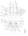
- Fig. 1 shows a cross section of an embodiment of the hinge 1, which is pressed into a track lever 2.
- the articulated connection consists of an inner joint element 3 in the form of a ring, the outer peripheral surface of which largely has the shape of a spherical segment.
- This outer circumferential surface coincides with the curved sliding surface 4, which constitutes a theoretical surface in which the sliding of the inner joint element takes place on two outer joint elements 5.
- the outer joint members are made annular and have on their inner peripheral surface the shape of a spherical portion having the same radius as the ball portion constituting the outer peripheral surface of the inner joint member 3.
- This inner circumferential surface of the outer joint elements 5 also coincides with the curved sliding surface 4.
- the outer joint elements 5 are pressed into a bore 6 such that the clearance between the inner joint element 3 and the outer joint elements 5 is low and the joint elements remain movable relative to each other. Between the outer joint elements 5 there is a cavity 7 into which grease can be injected through a bore in the track lever 2 in order to lubricate the joint connection.
- the articulated connection 1 has two sealing rings 8, which each consist of a sealing ring body 9, a first, inner sealing lip 10 and a second, outer sealing lip 11.
- the sealing lips 10 and 11 are annular and arranged around the same central axis as the hinge elements 3 and 5.
- the sealing rings 8, like the outer joint elements 5, are pressed into the bore 6 in the track lever 2 and abut axially on the outer joint elements 5.
- an oversize 12 between the bore 6 and the rings 8 is provided.
- the rings are in the FIG. 1 shown in undeformed state, so that the overlap 12 results with the material of the steering lever 2.
- the excess between the sealing rings 8 and the bore 6 is advantageously 0.5 mm.
- the inner Sealing lip 10 With the inner joint member 3, which is designated by the reference numeral 13.
- the overlap results from the fact that the sealing ring is shown in undeformed state.
- the sealing lip 10 will deform in the radial direction with respect to the sliding surface 4 so far that it does not penetrate into the inner joint member 3.
- the deformation results in a bias with which the inner sealing lip 10 is pressed against the inner joint member 3.
- the deformation path of the inner sealing lip is 1 mm.
- the sealing lip 10 is formed with respect to the sliding surface 4 so that forms a wedge-shaped annular gap 23 with a wedge-shaped cross section between the sliding surface 4 and the inner circumferential surface of the lip 10.
- the cross section of the sealing lip 10 is designed to be substantially parallel or slightly tapered towards the tip.
- the sealing lip 10 has an edge which is designed with a small edge radius so that it can strip off grease and / or dirt on the outer peripheral surface of the inner joint element 3 and ensures good tightness.
- the sealing lip 10 is integrally connected to the sealing ring body 9.
- the second, outer sealing lip 11 is also integrally connected to the sealing ring body 9.
- the sealing ring 8 On its outer circumference, the sealing ring 8 has a groove 14 which adjoins the second sealing lip 11 and the sealing ring body.
- the outer sealing lip has a cross section in the transition to the sealing ring body, which is less than the cross section of the outer lip 11 at the farther from the sealing ring body 9 remote locations. Due to the thin location at the transition between second lip 11 and sealing ring body 9, which is effected by the groove 14, the second lip 11 can cover a path in the direction of the sealing ring body 9 without material overload, which is limited by the complete compression of the groove 14. In this fully compressed state, no material overload occurs on the sealing ring 8, in particular on the second sealing lip 11.
- the groove 14 In the open state, the groove 14 also has the effect that exuding injection or cleaning water exerts pressure in the groove and enlarge it examined. As a result, the outer lip 11 is pushed further outwards, which causes an increase in the sealing effect in the installed state of the joint connection. In the case of strong external influences, the seal is thus self-reinforcing and intrinsically safe.
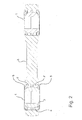
- Fig. 2 shows a track lever 2 with two articulated joints 1.
- the articulated joints 1 are identical to the embodiment shown in FIG Fig. 1 is shown constructed.
- the two joints in the track lever 2 are identical.
- Fig. 3 shows a cross section through a hinge joint 1 with an inner joint member 3, two outer joint elements 5 and two sealing rings 8.
- the hinge joint is pressed with its outer joint elements 5 and the sealing rings 8 in a bore 6 of a steering lever 2.
- the articulated connection 1 is arranged between two connection elements 15, each having a bore 16, and fastened by a bolt 17 between the connection elements 15.
- the bolt 17 is inserted through a central bore in the inner joint member 3 and through the holes 16 of the connecting elements and secured with locking rings 18 on each of the outer side of the connecting elements 15.
- a screw with a nut can be used.
- the outer sealing lips 11 of the sealing rings 8 each overlap with inner surfaces of the connecting elements 15, which are formed as a sealing surface 20.
- An overlap 21 between the second sealing lips 11 of the sealing rings 8 and the sealing surfaces 20 is due to the fact that the sealing lips 11 are shown in their undeformed state. In fact, the lips 11 deform in the direction of the sealing ring body 9 of the seals 8, whereby a bias of the lips 11 results against the sealing surfaces 20.
- the overlap between the undeformed lip 11 and the sealing surface 20 is preferably 1 mm, alternatively, however, 2 mm or 0.5 mm are possible.
- a Einfädelungsverrundung 19 is provided at one edge of the sealing surfaces 20, slide along the axially most prominent edges of the lips 11 and during threading of the steering lever 2 between the connecting elements 15 gradually bent in the direction of the sealing ring body 9 become. Characterized a local material overload in the sealing lips 11 and thus destruction of parts of the most axially projecting edge of the lip 11 and thus also their sealing effect is avoided. In addition, the Einfädelungsverrundung 19 simplifies and speeds up the assembly process.
- the sealing effect is achieved both by the press fit 12 and by the abutment of the sealing ring body 9 to the outer Articulated elements 5 causes.
- each of the two mentioned effects can be sufficient on its own as a sealing effect.
- Both the first lip 10 and the second lip 11 thus form a valve through which grease can flow out of the articulated connection, whereas, however, water penetrating from the outside into the articulated connection is arrested.
- the aforementioned advantageous Abschmier mecanickeit contributes to increase the life of the joint.
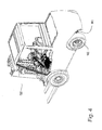
- FIG. 3 shows a forklift as an example of an industrial truck with a steerable axle 101 arranged in the rear of the vehicle.
- the rear wheels 102 of the forklift 100 are steerably attached to the axle 101 or in an alternative embodiment directly to the forklift 100 and are articulated by a toggle lever. having at least one sealed hinge connection according to the invention.
- the toggle lever and the sealed articulation are in the FIG. 4 Not shown.
- the front wheels of the forklift may also be articulated via a sealed articulated joint according to the invention.
Landscapes
- Engineering & Computer Science (AREA)
- General Engineering & Computer Science (AREA)
- Mechanical Engineering (AREA)
- Sealing Devices (AREA)
- Pivots And Pivotal Connections (AREA)
Abstract
Description
- Diese Erfindung betrifft eine abgedichtete Gelenkverbindung, insbesondere innerhalb eines Flurförderzeugs, zur Befestigung an einem Anschlusselement, wobei die Gelenkverbindung aufweist: ein inneres Gelenkelement und ein äußeres Gelenkelement, das das innere Gelenkelement ringförmig umgibt, und eine gekrümmte Gleitfläche zwischen dem inneren und dem äußeren Gelenkelement, durch die das innere Gelenkelement zu dem äußeren Gelenkelement wenigstens in einer Hauptrichtung drehbar ist.
- Im Stand der Technik sind Buchsen-Bolzen-Verbindungen bekannt, die als Gelenkverbindung beispielsweise von Spurhebeln von Flurförderzeugen dienen. Derartige Buchsen-Bolzen-Verbindungen werden jedoch auch an vielerlei Maschinen, wie etwa Baumaschinen, Holzverarbeitungsmaschinen, Maschinen der Baustoffindustrie und nicht zuletzt auch an anderen Einsatzorten als an Spurhebeln von Flurförderzeugen eingesetzt. Der Nachteil solcher ungedichteter Buchsen-Bolzen-Verbindungen liegt darin, dass sie insbesondere bei stärkerer Staub- oder sonstiger Schmutzbelastung der Umgebung starkem Verschleiß unterliegen. Daraus resultiert eine geringe Lebensdauer solcher Bauteile, was aufwendige Reparaturen erfordern kann.
- Eine nach dem Stand der Technik bekannte Verbesserung sind Abdichtungen solcher Buchsen-Bolzen-Verbindungen mit bekannten Dichtungsmitteln, wie etwa O-Ringen oder Radialwellendichtungen. In Pkw-Spurstangen werden häufig Kugelgelenke eingesetzt, die mit Manschetten geschützt sind. Jedoch sind auch die abgedichteten bekannten Gelenkverbindungen sehr starken äußeren Einflüssen nicht gewachsen, wie sie etwa bei der Reinigung mit einem Hochdruckreiniger auftreten.
- Aufgabe der Erfindung ist es daher, die Wirkung von Dichtungen an Gelenkverbindungen zu verbessern, um diese auch gegen extreme äußere Bedingungen zu schützen. Damit soll gleichzeitig eine bessere Langlebigkeit der Gelenkverbindungen erreicht werden.
- Gegenstand der Erfindung ist daher eine abgedichtete Gelenkverbindung, insbesondere innerhalb eines Flurförderzeugs, zur Befestigung an einem Anschlusselement, wobei die Gelenkverbindung aufweist: ein inneres Gelenkelement und ein äußeres Gelenkelement, das das innere Gelenkelement ringförmig umgibt, und eine gekrümmte Gleitfläche zwischen dem inneren und dem äußeren Gelenkelement, durch das das innere Gelenkelement zu dem äußeren Gelenkelement wenigstens in einer Hauptdrehrichtung drehbar ist. Die abgedichtete Gelenkanordnung ist erfindungsgemäß gekennzeichnet durch wenigstens einen Dichtring mit einem Dichtringkörper, der mit dem äußeren Gelenkelement wenigstens indirekt verbunden ist und die Gelenkverbindung nach außen abdichtet, wobei der Dichtring an dem Dichtringkörper eine erste ringförmige Lippe, die das innere Gelenkelement im Bereich der Gleitfläche abdichtend berührt, und eine zweite ringförmige Lippe zur Abdichtung der Gelenkverbindung unter Berührung einer Dichtfläche des Anschlusselements aufweist.
- Das Anschlusselement kann beispielsweise eine Lasche mit einer Bohrung sein, an der die Gelenkverbindung mit einem Bolzen befestigt ist. Statt einer Lasche können beispielsweise auch Streben, Träger, Platten oder dgl. ein Anschlusselement bilden. Das innere Gelenkelement kann in einem Ausführungsbeispiel eine Zylinderfläche als äußere Umfangsfläche aufweisen, die zumindest teilweise gleichzeitig die Gleitfläche zwischen dem inneren und dem äußeren Gelenkelement bildet. Die gekrümmte Gleitfläche kann jedoch auch in mehr als eine Richtung gekrümmt sein und beispielsweise als Abschnitt einer Kugeloberfläche, eines Ellipsoiden, eines Torus oder dgl. ausgebildet sein. Relevant ist dabei, dass sich das innere zu dem äußeren Gelenkelement in der Hauptdrehrichtung drehen lässt, wobei zusätzlich eine Bewegung in einer Schwenkrichtung möglich sein kann, die im Wesentlichen senkrecht zur Hauptdrehrichtung stattfindet. Die Hauptdrehrichtung unterscheidet sich von der Schwenkrichtung dadurch, dass die Hauptdrehrichtung einen größeren möglichen Bewegungswinkel hat.
- Die Gelenkverbindung kann auch zwischen zwei Anschlusselementen angeordnet sein, wobei dann vorteilhaft ein Dichtring für die Abdichtung zu dem Anschlusselement hin vorgesehen ist. Wenn die Gelenkverbindung als Gelenkverbindung mit zusätzlicher Schwenkbeweglichkeit ausgeführt ist, kann das innere Gelenkelement von dessen Mitte in Bezug auf die Drehachse der Hauptdrehrichtung aus sich verjüngend zu beiden Enden des inneren Gelenkelements hin in Richtung der Drehachse der Hauptdrehrichtung ausgeführt sein. In diesem Fall kann das äußere Gelenkelement aus zwei einzelnen äußeren Gelenkelementen bestehen, die eine der Außenkontur des inneren Gelenkelements angepasste Innenkontur aufweisen und auf dem sich verjüngenden Anteil des inneren Gelenkelements angeordnet sein. Die beiden äußeren Gelenkelemente sind vorteilhaft zueinander fixiert, so dass sie das innere Gelenkelement sicher umschließen. Das Spiel des inneren Gelenkelements kann durch optimale Einstellung der Abstände der äußeren Gelenkelemente bei gleichzeitiger Drehbarkeit in die Hauptdrehrichtung und in die Schwenkrichtung minimiert werden.
- In einem Ausführungsbeispiel kann das innere Gelenkelement an einem einzelnen Anschlusselement befestigt sein, wobei ein dem Anschlusselement abgewandter offener Teil der Gelenkverbindung beispielsweise durch eine metallene Kappe verschlossen sein kann. Bei diesem Ausführungsbeispiel ist nur ein Dichtring zwischen der Gelenkverbindung und dem Anschlusselement vorgesehen.
- Ein Vorteil des erfindungsgemäßen Dichtrings besteht darin, dass die erste und die zweite ringförmige Lippe eine zweistufige Dichtwirkung entfalten. Das Gelenkelement ist in einer ersten Stufe durch die Dichtwirkung der zweiten ringförmigen Lippe in Verbindung mit der Dichtfläche des Anschlusselements vor Umwelteinflüssen geschützt. Durch die Zusammenwirkung der Dichtfläche des Anschlusselements mit der zweiten ringförmigen Lippe wird ein Raum zwischen den genannten Elementen und dem inneren Gelenkelement abgeschlossen. Innerhalb dieses abgeschlossenen Raums befindet sich zwischen dem Gelenkelement und der zweiten ringförmigen Lippe eine zweite Dichtstelle, die aus der ersten ringförmigen Lippe und dem inneren Gelenkelement gebildet ist. Die innere, erste ringförmige Lippe wirkt als zweite Dichtungsstufe nur gegenüber eindringenden Stoffen, denen es gelungen ist, die äußere Dichtung aus der zweiten ringförmigen Lippe und der Dichtfläche des Anschlusselements zu überwinden. Sie ist daher einer erheblich geringeren Belastung ausgesetzt und normalerweise in der Lage, die Gelenkverbindung auch bei extrem starker Beaufschlagung mit Stoffen von außen, wie etwa beim Dampfstrahlen oder Druckluftreinigen, sicher vor eindringendem Material zu schützen. Dadurch wird die Lebensdauer der Gelenkverbindung erheblich erhöht. Die erste ringförmige Lippe hat außerdem eine Sicherheitsfunktion, die dann eingreift, wenn die äußere, zweite ringförmige Lippe aufgrund von Beschädigung oder Verschleiß zerstört ist und bei starken Einflüssen von außen keine Dichtwirkung mehr entfaltet. Dann bleibt das Innere des Gelenkelements durch die erste, innere ringförmige Lippe immer noch vor dem größten Teil der äußeren Einflüsse geschützt.
- Die Dichtungswirkung des Dichtringkörpers auf die Gelenkverbindung besteht darin, dass er den Raum um das äußere Gelenkelement besetzt und verhindert, dass von außen eindringendes Material die gekrümmte Gleitfläche über einen Weg an einer axialen Oberfläche des äußeren Gelenkelements erreicht, die zwischen dem inneren und dem äußeren Gelenkelement als theoretische Ebene ausgebildet ist, in der das Gleiten stattfindet.
- Der Dichtringkörper ist mit dem äußeren Gelenkelement im eingebauten Zustand in einem Ausführungsbeispiel über ein Auge eines Spurhebels oder einer vergleichbaren Aufnahme für das Gelenkelement dadurch verbunden, dass in das Auge oder eine entsprechende Bohrung sowohl das äußere Gelenkelement eingepresst ist als auch wenigstens ein Dichtring. Das äußere Gelenkelement und der Dichtring müssen sich dabei nicht berühren, weshalb ihre Verbindung ausschließlich über das Element realisiert sein kann, in das das äußere Gelenkelement und der Dichtring eingepresst sind.
- In einer weiteren Ausführungsform der Erfindung verläuft die erste ringförmige Lippe von dem Dichtringkörper aus im Wesentlichen in Richtung der gekrümmten Gleitfläche.
- Die erste ringförmige Lippe verläuft somit zumindest näherungsweise und zumindest über einen Abschnitt parallel zu der gekrümmten Gleitfläche. Die Begriffe "im Wesentlichen in Richtung der gekrümmten Gleitfläche" und "näherungsweise parallel" umfassen auch Winkel zwischen der ersten ringförmigen Lippe und der gekrümmten Gleitfläche bis etwa 45 Grad. Bei starkem Angriff von Material von außen, wie etwa einem Hochdruckreinigerstrahl, wird die erste ringförmige Lippe durch den von außen auftretenden Druck auf den Bereich der Gleitfläche des inneren Gelenkelements gedrückt, den die erste ringförmige Lippe überdeckt. Die Dichtwirkung zwischen der ersten ringförmigen Lippe und dem inneren Gelenkelement wird somit erhöht und somit das Eindringen von Fremdmaterial in das Gelenkelement erschwert.
- Die genannte Ausformung der ersten ringförmigen Lippe hat außerdem den Vorteil, dass Schmiermittel, das in die Gleitfläche des Gelenkelements gepresst wird, den Dichtring in Richtung der Umgebung des Gelenkelements passieren kann. Auf diese Weise kann verbrauchtes Schmiermittel, das beispielsweise mit Metallabrieb gefüllt ist, aus dem Gelenkelement entfernt und durch frisches Schmiermittel ersetzt werden.
- In einer weiteren Ausführungsform der Erfindung verläuft die zweite ringförmige Lippe von dem Dichtringkörper aus im Wesentlichen in Richtung von der Gleitfläche weg.
- Vorteilhaft verläuft die zweite ringförmige Lippe von dem Dichtringkörper aus außerdem in Richtung auf die Gleitfläche des Anschlusselements zu. Dadurch liegt sie im eingebauten Zustand vorteilhaft an der Gleitfläche des Anschlusselements an. Durch die Ausrichtung der zweiten ringförmigen Lippe von dem Dichtringkörper aus und im Wesentlichen in Richtung von der Gleitfläche weg reckt sie sich eindringendem Wasser, Schmutz, Druckluft oder dgl. derart entgegen, dass der Druck dieser Substanzen bewirkt, dass die zweite ringförmige Lippe an die Dichtfläche des Anschlusselements angedrückt wird. Außerdem ermöglicht diese Ausgestaltung der zweiten ringförmigen Lippe, dass durch die erste, innere ringförmige Lippe hindurchgedrücktes Schmiermittel der Gelenkverbindung auch durch die von der zweiten ringförmigen Lippe und der Dichtfläche des Anschlusselements gebildete Dichtstelle passieren kann. Diese Dichtstelle, wie auch die von der ersten ringförmigen Lippe gebildete Dichtstelle, haben eine Ventilfunktion, die bewirkt, dass die Dichtstellen in Richtung von der Gelenkverbindung nach außen durchlässig sind, während sie in der Gegenrichtung des Durchlass von Stoffen versperren.
- In einer weiteren Ausführungsform der Erfindung weist der Dichtungskörper eine an die zweite Lippe angrenzende Nut auf, die an einer der Gleitfläche abgewandten radialen Außenseite des Dichtungsrings liegt.
- Durch die genannte Nut wird bewirkt, dass das Andrücken der zweiten Lippe an die Dichtfläche des Anschlusselements optimiert stattfindet. Im Vergleich zu einer Ausführungsform ohne Nut entstehen bei einer Verformung der zweiten ringförmigen Lippe geringere Anpresskräfte, wodurch wiederum größere Verformungen der zweiten ringförmigen Lippe zur Erzeugung einer Anpresskraft ermöglicht werden. Kleinere Schwankungen des Vorspannweges führen daher nicht zu großen Änderungen der Anpresskraft und insgesamt zu einer gleichmäßigen und zuverlässigen Dichtwirkung. Entsprechend bewirkt die Nut, dass die zweite ringförmige Lippe auch vergleichsweise größere Schwenkbewegungen ausgleichen kann.
- In einer weiteren Ausführungsform der Erfindung sind die erste und/oder die zweite ringförmige Lippe so ausgebildet, dass sie im am Anschlusselement im eingebauten Zustand der abgedichteten Gelenkverbindung eine Vorspannung gegen die Gleitfläche bzw. die Dichtfläche des Anschlusselements aufweisen.
- Eine solche Vorspannung kann erreicht werden, indem die erste und/oder die zweite ringförmige Lippe so geformt sind, dass ihre freie Form im eingebauten Zustand mit den jeweiligen Anlageflächen überlappen bzw. diese durchdringen würden, was jedoch physikalisch nicht möglich ist, weshalb sich die im Vergleich zu den Anlageflächen weicheren, ringförmigen Lippen verformen und dabei eine Vorspannung gegen die Anlageflächen aufbauen. Als geeignetes Maß hat sich beispielsweise 1 mm Überlappung der zwei genannten Lippen in unverformtem Zustand mit den entsprechenden Gegenflächen herausgestellt. Alternativ können auch Überlappungen von 0,5 mm oder 2 mm vorgesehen werden.
- Als Materialien für den Dichtring nach der Erfindung sind beispielsweise verschiedene Gummisorten, Elastomere einschließlich Fluorkautschuk oder Silikone geeignet. Der Dichtringkörper kann in einem Ausführungsbeispiel aus einem Metallring bestehen, der von einem elastischen Material wenigstens teilweise umgeben ist.
- In einer weiteren Ausführungsform ist die Gleitfläche in zwei Richtungen gekrümmt, und weist insbesondere die Form eines Kugelflächenabschnitts auf.
- Mit dieser Form der Gleitfläche, insbesondere der Form eines Kugelflächenabschnitts, ist eine optimale Schwenkbewegung der Gelenkverbindung möglich. Alternativ kann auch eine Gelenkverbindung mit zylindrischer Gleitfläche und Spiel zwischen dem inneren und dem äußeren Gelenkelement vorgesehen werden, um Schwenken zu ermöglichen, wobei diese Lösung weniger bevorzugt ist.
- Ein weiterer Aspekt der Erfindung betrifft einen Spurhebel mit einer abgedichteten Gelenkverbindung nach der Erfindung.
- Die vorgeschlagene Gelenkverbindung kann in einem Spurhebel, insbesondere eines Flurförderzeugs besonders vorteilhaft zur Anwendung kommen. Ein solcher Spurhebel muss große Drehbewegungen in der Hauptdrehrichtung ausführen können und kleine Schwenkbewegungen ausführen können, um Spiel und Besonderheiten der Fahrwerksgeometrie ausgleichen zu können.
- In einer Ausführungsform des Spurhebels weist dieser zwei abgedichtete Gelenkverbindungen für jeweils zwei Anschlusselemente, zwischen denen die Gelenkverbindungen jeweils angeordnet sind, und vier Dichtringe auf, wobei jedem Anschlusselement jeweils ein Dichtring zugeordnet ist.
- Ein solcher Spurhebel kommt vorteilhaft in Flurförderzeugen zum Einsatz, wo er zwischen einem Achsschenkel und einer Lenkeinrichtung angeordnet werden kann. Aufgrund der durchgängigen Dichtung an allen Anschlusselementen ist ein solcher Spurhebel besonders langlebig und für die Reinigung mit Hochdruckreinigern geeignet.
- In einer weiteren Ausführungsform des Spurhebels ist in den Spurhebel ein Dichtring einer abgedichteten Gelenkverbindung eingepresst.
- Nach dem Stand der Technik werden Gelenkverbindungen beispielsweise in Augen von Spurhebeln eingepresst. Eine in axialer Richtung des Auges breitere Ausführung des Auges ermöglicht, auf einer oder beiden Seiten des Spurhebels zusätzlich zu der Gelenkverbindung einen Dichtring einzupressen. Der Dichtring kann auf diese Weise dicht und mit geringem Aufwand an dem Spurhebel befestigt werden.
- In einer weiteren Ausführungsform des Spurhebels ist der Außendurchmesser des Dichtringkörpers um 0,5 mm größer als die Bohrung in dem Spurhebel.
- Auf diese Weise entsteht ein Übermaß der Passung zwischen der Bohrung in dem Spurhebel und dem Dichtringkörper, die für eine dichte Verbindung zwischen dem Dichtring und dem Spurhebel bei geeigneten Presskräften sorgt.
- Ein weiterer Aspekt der Erfindung betrifft ein Flurförderzeug, das ein Anschlusselement und eine daran befestigte abgedichtete Gelenkverbindung nach der Erfindung aufweist.
- Ein solches Flurförderzeug weist die abgedichtete Gelenkverbindung vorzugsweise an mindestens einem seiner Spurhebel auf, wodurch die entsprechenden Gelenkverbindungen und die damit verbundenen Teile mit einem Hochdruckreiniger gereinigt werden können, ohne dass darunter die Lebensdauer der Gelenke leidet. Alternativ oder zusätzlich können entsprechende Gelenkverbindungen an anderen beweglichen Teilen des Flurförderzeugs vorgesehen sein, etwa an einer Gabelzinkenverstellung, an den Aufhängungspunkten von Hydraulikzylindern oder an anderen Druck- oder Zugelementen.
- In einer Ausführungsform des Flurförderzeugs weist dieses zwei Anschlusselemente auf, denen eine abgedichtete Gelenkverbindung mit zwei Dichtringen zugeordnet ist.
- Die Ausführung mit zwei Anschlusselementen, die eine abgedichtete Gelenkverbindung umfassen, welche mit zwei Dichtringen versehen ist, ist, wenn sie die Gelenkverbindung von beiden Seiten einschließt, mechanisch besonders vorteilhaft, da das Vorsehen von zwei Anschlusselementen zu weniger Biegekräften in denselben führen kann, wenn Kräfte über die Gelenkverbindung in die Anschlusselemente eingeleitet werden. Dies kann im Vergleich zu einer Konstruktion mit nur einem Anschlusselement zu Materialersparnis führen.
- In einer weiteren Ausführungsform des Flurförderzeugs weist wenigstens ein Anschlusselement eine Einführungsfase oder eine Einführungsrundung an einer Kante der Dichtfläche des Anschlusselements auf.
- Eine solche Einführungsfase oder Einführungsrundung bewirkt, dass beim Positionieren der Dichtung einer Gelenkverbindung an der Dichtfläche, insbesondere, wenn die Dichtung über die Dichtfläche parallel zu derselben an ihre Einbauposition geschoben wird, die Dichtung durch die Einführungsfase oder -rundung vorgespannt wird, wobei insbesondere bei einer Einführungsrundung der Dichtring durch scharfe Kanten nicht beschädigt und somit die Dichtwirkung nicht beeinträchtigt wird.
- Ein weiterer Aspekt der Erfindung betrifft einen Dichtring für eine Gelenkverbindung nach der Erfindung mit den Merkmalen des kennzeichnenden Teils des Anspruchs 1.
- Der Dichtring kann jedes der Merkmale aufweisen, die im Zusammenhang mit einer Gelenkverbindung, einem Schubhebel oder einem Flurförderzeug einschließlich deren Ausführungsformen und Ausführungsbeispiele genannt ist. In jedem Fall weist er die Merkmale des im kennzeichnenden Teil der in Anspruch 1 genannten Merkmale eines Dichtrings auf.
- Die Erfindung wird nachfolgend unter Bezugnahme auf die anliegenden Zeichnungen beispielhaft und nicht einschränkend im Detail beschrieben.
- Fig. 1
- ist ein Querschnitt durch eine Ausführungsform der Gelenkverbindung.
- Fig. 2
- ist ein Querschnitt durch eine Ausführungsform eines Spurhebels mit zwei Gelenkverbindungen.
- Fig. 3
- ist ein Querschnitt durch eine Gelenkverbindung, die einen Spurhebel mit zwei Anschlusselementen gelenkig verbindet.
- Fig. 4
- ist eine perspektivische Darstellung eines Gabelstaplers als Beispiel für ein Flurförderzeug, in dem die Erfindung zur Anwendung kommt.
-
Fig. 1 zeigt einen Querschnitt einer Ausführungsform der Gelenkverbindung 1, die in einen Spurhebel 2 eingepresst ist. Die Gelenkverbindung besteht aus einem inneren Gelenkelement 3 in Form eines Rings, dessen Außenumfangsfläche größtenteils die Form eines Kugelabschnitts aufweist. Diese Außenumfangsfläche fällt mit der gekrümmten Gleitfläche 4 zusammen, die eine theoretische Fläche darstellt, in der das Abgleiten des inneren Gelenkelements an zwei äußeren Gelenkelementen 5 stattfindet. Die äußeren Gelenkelemente sind ringförmig ausgeführt und weisen auf ihrer inneren Umfangsfläche die Form eines Kugelabschnitts mit demselben Radius wie der Kugelabschnitt, der die äußere Umfangsfläche des inneren Gelenkelements 3 bildet, auf. Diese innere Umfangsfläche der äußeren Gelenkelemente 5 fällt ebenfalls mit der gekrümmten Gleitfläche 4 zusammen. Die äußeren Gelenkelemente 5 sind in einer Bohrung 6 derart eingepresst, dass das Spiel zwischen dem inneren Gelenkelement 3 und den äußeren Gelenkelementen 5 gering ist und die Gelenkelemente zueinander beweglich bleiben. Zwischen den äußeren Gelenkelementen 5 befindet sich ein Hohlraum 7, in den durch eine Bohrung in dem Spurhebel 2 Fett eingepresst werden kann, um die Gelenkverbindung zu schmieren. - Weiter weist die Gelenkverbindung 1 zwei Dichtringe 8 auf, die jeweils aus einem Dichtringkörper 9, einer ersten, inneren Dichtlippe 10 und einer zweiten, äußeren Dichtlippe 11 bestehen. Die Dichtlippen 10 und 11 sind ringförmig ausgebildet und um dieselbe Mittelachse wie die Gelenkelemente 3 und 5 angeordnet. Die Dichtringe 8 sind ebenso wie die äußeren Gelenkelemente 5 in die Bohrung 6 in dem Spurhebel 2 eingepresst und liegen axial an den äußeren Gelenkelementen 5 an. Um eine Dichtigkeit und eine geeignete Presskraft beim Einpressen der Dichtungen 8 in die Bohrung 6 zu gewährleisten, ist ein Übermaß 12 zwischen der Bohrung 6 und den Ringen 8 vorgesehen. Die Ringe sind in der
Figur 1 in unverformtem Zustand dargestellt, so dass sich die Überlappung 12 mit dem Material des Spurhebels 2 ergibt. Das Übermaß zwischen den Dichtringen 8 und der Bohrung 6 beträgt vorteilhaft 0,5 mm. Weiter ergibt sich eine Überlappung von Material der inneren Dichtlippe 10 mit dem inneren Gelenkelement 3, die mit der Bezugsziffer 13 gekennzeichnet ist. Die Überlappung ergibt sich dadurch, dass der Dichtring in unverformtem Zustand dargestellt ist. In der Realität wird sich die Dichtlippe 10 in radialer Richtung in Bezug auf die Gleitfläche 4 so weit verformen, dass sie nicht in das innere Gelenkelement 3 eindringt. Durch die Verformung ergibt sich eine Vorspannung, mit der die innere Dichtlippe 10 an das innere Gelenkelement 3 angepresst wird. Vorteilhaft beträgt der Verformungsweg der inneren Dichtlippe 1 mm. - Die Dichtlippe 10 ist in Bezug auf die Gleitfläche 4 so ausgeformt, dass sich zwischen der Gleitfläche 4 und der inneren Umfangsfläche der Lippe 10 ein keilförmiger Ringspalt 23 mit keilförmigem Querschnitt ausbildet. Der Querschnitt der Dichtlippe 10 ist im Wesentlichen parallel oder zur Spitze hin leicht verjüngt ausgeführt. Die Dichtlippe 10 weist eine Kante auf, die mit einem geringen Kantenradius ausgeführt ist, so dass sie Fett und/oder Schmutz auf der äußeren Umfangsfläche des inneren Gelenkelements 3 abstreifen kann und für eine gute Dichtigkeit sorgt. Die Dichtlippe 10 ist einstückig mit dem Dichtringkörper 9 verbunden.
- Die zweite, äußere Dichtlippe 11 ist ebenfalls einstückig mit dem Dichtringkörper 9 verbunden. An seinem Außenumfang weist der Dichtring 8 eine Nut 14 auf, die an die zweite Dichtlippe 11 und den Dichtringkörper angrenzt. Die äußere Dichtlippe hat einen Querschnitt im Übergang zum Dichtringkörper, der geringer ist als der Querschnitt der äußeren Lippe 11 an den weiter von dem Dichtringkörper 9 entfernten Stellen. Durch die Dünnstelle am Übergang zwischen zweiter Lippe 11 und Dichtringkörper 9, der durch die Nut 14 bewirkt wird, kann die zweite Lippe 11 ohne Materialüberlastung einen Weg in Richtung des Dichtringkörpers 9 zurücklegen, der durch das vollständige Zusammendrücken der Nut 14 begrenzt wird. In diesem vollständig zusammengedrückten Zustand tritt noch keine Materialüberlastung an dem Dichtring 8, insbesondere an der zweiten Dichtlippe 11 auf. In geöffnetem Zustand hat die Nut 14 außerdem den Effekt, dass von außen zuströmendes Spritz- oder Reinigungswasser Druck in der Nut ausübt und sie zu vergrößern sucht. Dadurch wird die äußere Lippe 11 weiter nach außen gedrängt, was im eingebauten Zustand der Gelenkverbindung eine Verstärkung der Dichtwirkung bewirkt. Bei starken Einflüssen von außen ist die Dichtung somit selbstverstärkend und eigensicher.
-
Fig. 2 zeigt einen Spurhebel 2 mit zwei Gelenkverbindungen 1. Die Gelenkverbindungen 1 sind identisch zu der Ausführungsform, die inFig. 1 gezeigt ist, aufgebaut. Die beiden Gelenkverbindungen in dem Spurhebel 2 sind identisch ausgeführt. -
Fig. 3 zeigt einen Querschnitt durch eine Gelenkverbindung 1 mit einem inneren Gelenkelement 3, zwei äußeren Gelenkelementen 5 sowie zwei Dichtringen 8. Die Gelenkverbindung ist mit ihren äußeren Gelenkelementen 5 und den Dichtringen 8 in eine Bohrung 6 eines Spurhebels 2 eingepresst. Die Gelenkverbindung 1 ist zwischen zwei Anschlusselementen 15 mit jeweils einer Bohrung 16 angeordnet und mit einem Bolzen 17 zwischen den Anschlusselementen 15 befestigt. Der Bolzen 17 ist durch eine Mittelbohrung in dem inneren Gelenkelement 3 sowie durch die Bohrungen 16 der Anschlusselemente gesteckt und mit Sicherungsringen 18 auf jeweils der Außenseite der Anschlusselemente 15 gesichert. Alternativ kann auch eine Schraube mit einer Mutter verwendet werden. - Die äußeren Dichtlippen 11 der Dichtringe 8 überlappen jeweils mit inneren Oberflächen der Anschlusselemente 15, die als Dichtfläche 20 ausgebildet sind. Eine Überlappung 21 zwischen den zweiten Dichtlippen 11 der Dichtringe 8 und der Dichtflächen 20 ist dadurch begründet, dass die Dichtlippen 11 in ihrem unverformten Zustand dargestellt sind. Tatsächlich verformen sich die Lippen 11 in Richtung des Dichtringkörpers 9 der Dichtungen 8, wodurch sich eine Vorspannung der Lippen 11 gegen die Dichtflächen 20 ergibt. Die Überlappung zwischen der unverformten Lippe 11 und der Dichtfläche 20 beträgt vorzugsweise 1 mm, alternativ sind jedoch auch 2 mm oder 0,5 mm möglich. Um das Einfädeln des Spurhebels 2 mit der Gelenkverbindung 1 zwischen die Anschlusselemente 15 zu erleichtern und insbesondere die zweiten Dichtlippen 11 zu schonen, ist an einem Rand der Dichtflächen 20 eine Einfädelungsverrundung 19 vorgesehen, an der die in axialer Richtung am weitesten vorstehenden Kanten der Lippen 11 entlanggleiten und beim Einfädeln des Spurhebels 2 zwischen die Anschlusselemente 15 allmählich in Richtung des Dichtringkörpers 9 gebogen werden. Dadurch wird eine lokale Materialüberlastung in den Dichtlippen 11 und somit eine Zerstörung von Teilen der am weitesten axial vorstehenden Kante der Lippe 11 und damit auch ihrer Dichtwirkung vermieden. Zudem vereinfacht und beschleunigt die Einfädelungsverrundung 19 den Montagevorgang.
- Anhand der
Fig. 3 lässt sich die Dichtungswirkung der Dichtringe 8 detailliert erklären. Spritz- oder Reinigungswasser kann in den Spalten 22 zwischen dem Spurhebel 2 und den Anschlusselementen 15 in Richtung der Gelenkverbindung 1 vordringen. Das eindringende Wasser trifft auf die Nut 14 sowie seitlich auf den Dichtringkörper 9 und die äußere Lippe 11. Durch den Druck von eindringendem Wasser wird die Nut aufgeweitet und die Lippe 11 stärker an die Dichtfläche 20 angepresst. Dadurch erhöht eindringendes Wasser die Dichtwirkung, was das Eindringen von Wasser in das Innere der Gelenkverbindung erschwert. Der Dichtringkörper 9 bildet bei dieser Dichtwirkung eine Barriere zwischen den Spalten 22 und dem ringförmigen Keilspalt zwischen den ersten Lippen 10 und der äußeren Umfangsfläche des inneren Gelenkelements 3. Die Dichtwirkung wird sowohl durch die Presspassung 12 als auch durch das Anliegen des Dichtringkörpers 9 an den äußeren Gelenkelementen 5 bewirkt. Jede der beiden genannten Wirkungen kann jedoch für sich allein als Dichtwirkung ausreichen. Wenn durch den Hohlraum 7 zwischen den äußeren Gelenkelementen 5 Fett in die Gelenkverbindung 1 gepresst wird, strömt dieses durch den zum Gleiten erforderlichen Zwischenraum zwischen dem inneren Gelenkelement 3 und den äußeren Gelenkelementen 5, so dass es den ringförmigen Keilspalt 23 zwischen der innerne Lippe 10 und dem inneren Gelenkelement 3 füllt. Wenn dieser Keilspalt 23 gefüllt ist, tritt Fett an der ersten Lippe 10 vorbei in einen Zwischenraum 24 ein. Wenn dieser Zwischenraum 24 mit Fett gefüllt ist, so tritt Fett an der zweiten Dichtlippe 11 vorbei in den Ringspalt 22 aus. Beim Abschmieren kann durch das Austreten dieses Fettes festgestellt werden, dass die Gelenkverbindung durchgeschmiert ist. Sowohl die erste Lippe 10 als auch die zweite Lippe 11 bilden somit ein Ventil, durch das Fett aus der Gelenkverbindung ausströmen kann, wogegen jedoch von außen in die Gelenkverbindung eindringendes Wasser aufgehalten wird. Auch die genannte vorteilhafte Abschmiermöglichkeit trägt zur Erhöhung der Lebensdauer der Gelenkverbindung bei. - Die
Fig. 4 zeigt einen Gabelstapler als Beispiel für ein Flurförderzeug mit einer im Heck des Fahrzeugs angeordneten lenkbaren Achse 101. Die hinteren Räder 102 des Gabelstaplers 100 sind lenkbar an der Achse 101 oder in einer alternativen Ausführungsform unmittelbar an dem Gabelstapler 100 befestigt und werden von einem Spurhebel angelenkt, der wenigstens eine abgedichtete Gelenkverbindung nach der Erfindung aufweist. Der Spurhebel und die abgedichtete Gelenkverbindung sind in derFigur 4 nicht gezeigt. In einer alternativen Ausführungsform können auch die Vorderräder des Gabelstaplers über eine erfindungsgemäße abgedichtete Gelenkverbindung angelenkt sein.
Claims (13)
- Abgedichtete Gelenkverbindung (1), insbesondere innerhalb eines Flurförderzeugs,
zur Befestigung an einem Anschlusselement (15),
wobei die Gelenkverbindung (1) aufweist:ein inneres Gelenkelement (3) und ein äußeres Gelenkelement (5), das das innere Gelenkelement (3) ringförmig umgibt,eine gekrümmte Gleitfläche (4) zwischen dem inneren Gelenkelement (3) und dem äußeren Gelenkelement (5),durch die das erste innere Gelenkelement (3) zu dem äußeren Gelenkelement (5) wenigstens in eine Hauptdrehrichtung drehbar ist,gekennzeichnet durchwenigstens einen Dichtring (8) mit einem Dichtringkörper (9), der mit dem äußeren Gelenkelement (5) wenigstens indirekt verbunden ist unddie Gelenkverbindung nach außen abdichtet,wobei der Dichtringkörper (9) eine erste ringförmige Lippe (10) aufweist, die das innere Gelenkelement (3) im Bereich der Gleitfläche (4) abdichtend berührt und eine zweite ringförmige Lippe (11) zur Abdichtung der Gelenkverbindung (1) unter Berührung einer Dichtfläche (20) des Anschlusselements (15) aufweist. - Abgedichtete Gelenkverbindung (1) nach Anspruch 1, dadurch gekennzeichnet, dass die erste ringförmige Lippe (10) von dem Dichtringkörper (9) aus im Wesentlichen in Richtung der gekrümmten Gleitfläche (4) verläuft.
- Abgedichtete Gelenkverbindung (1) nach Anspruch 1 oder 2, dadurch gekennzeichnet, dass die zweite ringförmige Lippe (11) von dem Dichtringkörper (9) aus im Wesentlichen von der Gleitfläche (4) weg verläuft.
- Abgedichtete Gelenkverbindung (1) nach einem der Ansprüche 1 bis 3, dadurch gekennzeichnet, dass der Dichtringkörper (9) eine an die zweite ringförmige Lippe (11) angrenzende Nut (14) aufweist, die an einer der Gleitfläche (4) abgewandten radialen Außenseite des Dichtrings (8) liegt.
- Abgedichtete Gelenkverbindung (1) nach einem der Ansprüche 1 bis 4, dadurch gekennzeichnet, dass die erste ringförmige Lippe (10) und/oder die zweite ringförmige Lippe (11) so ausgebildet sind, dass sie im am Anschlusselement (15) eingebauten Zustand der abgedichteten Gelenkverbindung (1) eine Vorspannung gegen die Gleitfläche (4) bzw. die Dichtfläche (20) des Anschlusselements (15) aufweisen.
- Abgedichtete Gelenkverbindung (1) nach einem der Ansprüche 1 bis 5, dadurch gekennzeichnet, dass die Gleitfläche (4) in zwei Richtungen gekrümmt ist, und insbesondere eine Kugelflächenabschnittsform aufweist.
- Spurhebel (2) mit einer abgedichteten Gelenkverbindung (1) nach einem der Ansprüche 1 bis 6.
- Spurhebel (2) nach Anspruch 7, dadurch gekennzeichnet, dass er zwei abgedichtete Gelenkverbindungen (1) für jeweils zwei Anschlusselemente (15), zwischen denen die Gelenkverbindungen (1) jeweils angeordnet sind, und vier Dichtringe (8) aufweist, wobei jedem Anschlusselement (15) jeweils ein Dichtring (8) zugeordnet ist.
- Spurhebel (2) nach einem der Ansprüche 7 oder 8, in den ein Dichtring (8) einer abgedichteten Gelenkverbindung (1) eingepresst ist.
- Flurförderzeug, dadurch gekennzeichnet, dass es ein Anschlusselement (15) und eine daran befestigte abgedichtete Gelenkverbindung (1) nach einem der Ansprüche 1 bis 6 aufweist.
- Flurförderzeug nach Anspruch 10, dadurch gekennzeichnet, dass es zwei Anschlusselemente (15) aufweist, denen eine abgedichtete Gelenkverbindung (1) mit zwei Dichtringen (8) zugeordnet ist.
- Flurförderzeug nach einem der Ansprüche 10 oder 11, dadurch gekennzeichnet, dass wenigstens ein Anschlusselement (15) eine Einführungsfase oder eine Einführungsrundung (19) an einer Kante der Dichtfläche (20) des Anschlusselements (15) aufweist.
- Dichtring (8) für eine Gelenkverbindung (1) nach einem der Ansprüche 1 bis 6 mit den Merkmalen des kennzeichnenden Teils des Anspruchs 1.
Applications Claiming Priority (1)
| Application Number | Priority Date | Filing Date | Title |
|---|---|---|---|
| DE102011086857A DE102011086857A1 (de) | 2011-11-22 | 2011-11-22 | Abgedichtete Gelenkverbindung |
Publications (3)
| Publication Number | Publication Date |
|---|---|
| EP2597325A2 true EP2597325A2 (de) | 2013-05-29 |
| EP2597325A3 EP2597325A3 (de) | 2016-06-15 |
| EP2597325B1 EP2597325B1 (de) | 2024-02-28 |
Family
ID=47227593
Family Applications (1)
| Application Number | Title | Priority Date | Filing Date |
|---|---|---|---|
| EP12192554.9A Active EP2597325B1 (de) | 2011-11-22 | 2012-11-14 | Abgedichtete Gelenkverbindung |
Country Status (2)
| Country | Link |
|---|---|
| EP (1) | EP2597325B1 (de) |
| DE (1) | DE102011086857A1 (de) |
Family Cites Families (7)
| Publication number | Priority date | Publication date | Assignee | Title |
|---|---|---|---|---|
| US3794392A (en) * | 1972-04-10 | 1974-02-26 | G Scott | Bearing seal |
| US3822890A (en) * | 1973-01-15 | 1974-07-09 | Roulements Soc Nouvelle | Bearing seals |
| US3822100A (en) * | 1973-02-16 | 1974-07-02 | Caterpillar Tractor Co | Joint for a spherical bearing |
| JPS6145617U (ja) * | 1984-08-29 | 1986-03-26 | トヨタ自動車株式会社 | 球面ブツシユのシ−ル構造 |
| DE3933163A1 (de) * | 1988-10-27 | 1990-05-03 | Toyoda Gosei Kk | Zylindrische daempfungsbuchse |
| US7367739B2 (en) * | 2004-08-02 | 2008-05-06 | Clark Equipment Company | Two component seal |
| DE102005029979A1 (de) * | 2005-06-28 | 2007-01-11 | Schaeffler Kg | Gelenklager |
-
2011
- 2011-11-22 DE DE102011086857A patent/DE102011086857A1/de not_active Ceased
-
2012
- 2012-11-14 EP EP12192554.9A patent/EP2597325B1/de active Active
Non-Patent Citations (1)
| Title |
|---|
| None |
Also Published As
| Publication number | Publication date |
|---|---|
| EP2597325A3 (de) | 2016-06-15 |
| EP2597325B1 (de) | 2024-02-28 |
| DE102011086857A1 (de) | 2013-05-23 |
Similar Documents
| Publication | Publication Date | Title |
|---|---|---|
| DE69729862T2 (de) | Dichtungsvorrichtung für lager und anordnung zum abdichten von einer lagervorrichtung | |
| DE4223166A1 (de) | Kugelfoermiges gleitlager | |
| DE69918910T2 (de) | Ringförmige Dichtung, insbesondere für eine Antriebswelle eines Kraftfahrzeuges | |
| EP2886896A2 (de) | Wälzlager mit Dichtungseinheit für Wälzlager | |
| WO2013093900A1 (de) | Maul- oder klauenförmige spaltdichtung | |
| DE112018004085T5 (de) | Verbesserte kugelpfannenbaugruppe und verfahren zur herstellung | |
| DE10239266B4 (de) | Kugelgelenk mit Dichtungsbalg | |
| DE3207488A1 (de) | Lagerabdichtung fuer dichtverbindungen zwischen zapfen und lagerjochteilen einer universalverbindung | |
| DE10045422A1 (de) | Drehgelenkanordnung und Verfahren zum Erstellen derselben | |
| EP1432920B1 (de) | Kugelgelenk | |
| DE19502246A1 (de) | Dichtungseinrichtung für ein Kreuzgelenk | |
| DE102004046676A1 (de) | Kugelgelenk mit Dichtungsbalg | |
| DE10315850A1 (de) | Kombinationsdichtung | |
| EP1138968B1 (de) | Labyrinthdichtung für eine Gelenkkreuzwelle | |
| EP2527694B1 (de) | Maul- oder klauenförmige Spaltdichtung | |
| EP3688326A1 (de) | Gelenkanordnung | |
| DE2728506A1 (de) | Abgedichtetes gleiskettengelenk | |
| DE102017209890A1 (de) | Kugelgelenk für einen Zweipunktlenker sowie Zweipunktlenker mit einem solchen Kugelgelenk | |
| EP3093537B1 (de) | Abstreifanordnung und abdichtvorrichtung | |
| EP2597325B1 (de) | Abgedichtete Gelenkverbindung | |
| DE4040720C1 (de) | ||
| DE102008041829B4 (de) | Gelenkverbindungsanordnung in einer Scheibenwischvorrichtung | |
| DE102015010782A1 (de) | Ventil | |
| DE10157935A1 (de) | Befestigungsring für eine Dichtmanschette eines Kugelgelenks | |
| DE102009042936A1 (de) | Abgedichtetes Kugelgelenk und Dichtungsbalg für ein solches Kugelgelenk |
Legal Events
| Date | Code | Title | Description |
|---|---|---|---|
| PUAI | Public reference made under article 153(3) epc to a published international application that has entered the european phase |
Free format text: ORIGINAL CODE: 0009012 |
|
| AK | Designated contracting states |
Kind code of ref document: A2 Designated state(s): AL AT BE BG CH CY CZ DE DK EE ES FI FR GB GR HR HU IE IS IT LI LT LU LV MC MK MT NL NO PL PT RO RS SE SI SK SM TR |
|
| AX | Request for extension of the european patent |
Extension state: BA ME |
|
| RAP1 | Party data changed (applicant data changed or rights of an application transferred) |
Owner name: JUNGHEINRICH AKTIENGESELLSCHAFT |
|
| PUAL | Search report despatched |
Free format text: ORIGINAL CODE: 0009013 |
|
| AK | Designated contracting states |
Kind code of ref document: A3 Designated state(s): AL AT BE BG CH CY CZ DE DK EE ES FI FR GB GR HR HU IE IS IT LI LT LU LV MC MK MT NL NO PL PT RO RS SE SI SK SM TR |
|
| AX | Request for extension of the european patent |
Extension state: BA ME |
|
| RIC1 | Information provided on ipc code assigned before grant |
Ipc: F16C 23/04 20060101ALI20160510BHEP Ipc: F16C 11/06 20060101AFI20160510BHEP Ipc: F16C 33/74 20060101ALI20160510BHEP |
|
| 17P | Request for examination filed |
Effective date: 20160701 |
|
| RBV | Designated contracting states (corrected) |
Designated state(s): AL AT BE BG CH CY CZ DE DK EE ES FI FR GB GR HR HU IE IS IT LI LT LU LV MC MK MT NL NO PL PT RO RS SE SI SK SM TR |
|
| STAA | Information on the status of an ep patent application or granted ep patent |
Free format text: STATUS: EXAMINATION IS IN PROGRESS |
|
| 17Q | First examination report despatched |
Effective date: 20170327 |
|
| P01 | Opt-out of the competence of the unified patent court (upc) registered |
Effective date: 20230628 |
|
| RIC1 | Information provided on ipc code assigned before grant |
Ipc: F16C 7/02 20060101ALN20230721BHEP Ipc: F16C 33/74 20060101ALI20230721BHEP Ipc: F16C 23/04 20060101ALI20230721BHEP Ipc: F16C 11/06 20060101AFI20230721BHEP |
|
| GRAP | Despatch of communication of intention to grant a patent |
Free format text: ORIGINAL CODE: EPIDOSNIGR1 |
|
| STAA | Information on the status of an ep patent application or granted ep patent |
Free format text: STATUS: GRANT OF PATENT IS INTENDED |
|
| RIC1 | Information provided on ipc code assigned before grant |
Ipc: F16C 7/02 20060101ALN20230830BHEP Ipc: F16C 33/74 20060101ALI20230830BHEP Ipc: F16C 23/04 20060101ALI20230830BHEP Ipc: F16C 11/06 20060101AFI20230830BHEP |
|
| INTG | Intention to grant announced |
Effective date: 20230913 |
|
| GRAS | Grant fee paid |
Free format text: ORIGINAL CODE: EPIDOSNIGR3 |
|
| GRAA | (expected) grant |
Free format text: ORIGINAL CODE: 0009210 |
|
| STAA | Information on the status of an ep patent application or granted ep patent |
Free format text: STATUS: THE PATENT HAS BEEN GRANTED |
|
| AK | Designated contracting states |
Kind code of ref document: B1 Designated state(s): AL AT BE BG CH CY CZ DE DK EE ES FI FR GB GR HR HU IE IS IT LI LT LU LV MC MK MT NL NO PL PT RO RS SE SI SK SM TR |
|
| REG | Reference to a national code |
Ref country code: GB Ref legal event code: FG4D Free format text: NOT ENGLISH |
|
| REG | Reference to a national code |
Ref country code: CH Ref legal event code: EP |
|
| REG | Reference to a national code |
Ref country code: DE Ref legal event code: R096 Ref document number: 502012017248 Country of ref document: DE |
|
| REG | Reference to a national code |
Ref country code: IE Ref legal event code: FG4D Free format text: LANGUAGE OF EP DOCUMENT: GERMAN |
|
| REG | Reference to a national code |
Ref country code: LT Ref legal event code: MG9D |
|
| PG25 | Lapsed in a contracting state [announced via postgrant information from national office to epo] |
Ref country code: IS Free format text: LAPSE BECAUSE OF FAILURE TO SUBMIT A TRANSLATION OF THE DESCRIPTION OR TO PAY THE FEE WITHIN THE PRESCRIBED TIME-LIMIT Effective date: 20240628 |
|
| REG | Reference to a national code |
Ref country code: NL Ref legal event code: MP Effective date: 20240228 |
|
| PG25 | Lapsed in a contracting state [announced via postgrant information from national office to epo] |
Ref country code: LT Free format text: LAPSE BECAUSE OF FAILURE TO SUBMIT A TRANSLATION OF THE DESCRIPTION OR TO PAY THE FEE WITHIN THE PRESCRIBED TIME-LIMIT Effective date: 20240228 |
|
| PG25 | Lapsed in a contracting state [announced via postgrant information from national office to epo] |
Ref country code: GR Free format text: LAPSE BECAUSE OF FAILURE TO SUBMIT A TRANSLATION OF THE DESCRIPTION OR TO PAY THE FEE WITHIN THE PRESCRIBED TIME-LIMIT Effective date: 20240529 |
|
| PG25 | Lapsed in a contracting state [announced via postgrant information from national office to epo] |
Ref country code: HR Free format text: LAPSE BECAUSE OF FAILURE TO SUBMIT A TRANSLATION OF THE DESCRIPTION OR TO PAY THE FEE WITHIN THE PRESCRIBED TIME-LIMIT Effective date: 20240228 Ref country code: RS Free format text: LAPSE BECAUSE OF FAILURE TO SUBMIT A TRANSLATION OF THE DESCRIPTION OR TO PAY THE FEE WITHIN THE PRESCRIBED TIME-LIMIT Effective date: 20240528 Ref country code: NL Free format text: LAPSE BECAUSE OF FAILURE TO SUBMIT A TRANSLATION OF THE DESCRIPTION OR TO PAY THE FEE WITHIN THE PRESCRIBED TIME-LIMIT Effective date: 20240228 |
|
| PG25 | Lapsed in a contracting state [announced via postgrant information from national office to epo] |
Ref country code: ES Free format text: LAPSE BECAUSE OF FAILURE TO SUBMIT A TRANSLATION OF THE DESCRIPTION OR TO PAY THE FEE WITHIN THE PRESCRIBED TIME-LIMIT Effective date: 20240228 |
|
| PG25 | Lapsed in a contracting state [announced via postgrant information from national office to epo] |
Ref country code: RS Free format text: LAPSE BECAUSE OF FAILURE TO SUBMIT A TRANSLATION OF THE DESCRIPTION OR TO PAY THE FEE WITHIN THE PRESCRIBED TIME-LIMIT Effective date: 20240528 Ref country code: NO Free format text: LAPSE BECAUSE OF FAILURE TO SUBMIT A TRANSLATION OF THE DESCRIPTION OR TO PAY THE FEE WITHIN THE PRESCRIBED TIME-LIMIT Effective date: 20240528 Ref country code: NL Free format text: LAPSE BECAUSE OF FAILURE TO SUBMIT A TRANSLATION OF THE DESCRIPTION OR TO PAY THE FEE WITHIN THE PRESCRIBED TIME-LIMIT Effective date: 20240228 Ref country code: LT Free format text: LAPSE BECAUSE OF FAILURE TO SUBMIT A TRANSLATION OF THE DESCRIPTION OR TO PAY THE FEE WITHIN THE PRESCRIBED TIME-LIMIT Effective date: 20240228 Ref country code: IS Free format text: LAPSE BECAUSE OF FAILURE TO SUBMIT A TRANSLATION OF THE DESCRIPTION OR TO PAY THE FEE WITHIN THE PRESCRIBED TIME-LIMIT Effective date: 20240628 Ref country code: HR Free format text: LAPSE BECAUSE OF FAILURE TO SUBMIT A TRANSLATION OF THE DESCRIPTION OR TO PAY THE FEE WITHIN THE PRESCRIBED TIME-LIMIT Effective date: 20240228 Ref country code: GR Free format text: LAPSE BECAUSE OF FAILURE TO SUBMIT A TRANSLATION OF THE DESCRIPTION OR TO PAY THE FEE WITHIN THE PRESCRIBED TIME-LIMIT Effective date: 20240529 Ref country code: FI Free format text: LAPSE BECAUSE OF FAILURE TO SUBMIT A TRANSLATION OF THE DESCRIPTION OR TO PAY THE FEE WITHIN THE PRESCRIBED TIME-LIMIT Effective date: 20240228 Ref country code: ES Free format text: LAPSE BECAUSE OF FAILURE TO SUBMIT A TRANSLATION OF THE DESCRIPTION OR TO PAY THE FEE WITHIN THE PRESCRIBED TIME-LIMIT Effective date: 20240228 Ref country code: BG Free format text: LAPSE BECAUSE OF FAILURE TO SUBMIT A TRANSLATION OF THE DESCRIPTION OR TO PAY THE FEE WITHIN THE PRESCRIBED TIME-LIMIT Effective date: 20240228 |
|
| PG25 | Lapsed in a contracting state [announced via postgrant information from national office to epo] |
Ref country code: PL Free format text: LAPSE BECAUSE OF FAILURE TO SUBMIT A TRANSLATION OF THE DESCRIPTION OR TO PAY THE FEE WITHIN THE PRESCRIBED TIME-LIMIT Effective date: 20240228 Ref country code: PT Free format text: LAPSE BECAUSE OF FAILURE TO SUBMIT A TRANSLATION OF THE DESCRIPTION OR TO PAY THE FEE WITHIN THE PRESCRIBED TIME-LIMIT Effective date: 20240628 |
|
| PG25 | Lapsed in a contracting state [announced via postgrant information from national office to epo] |
Ref country code: SE Free format text: LAPSE BECAUSE OF FAILURE TO SUBMIT A TRANSLATION OF THE DESCRIPTION OR TO PAY THE FEE WITHIN THE PRESCRIBED TIME-LIMIT Effective date: 20240228 Ref country code: PT Free format text: LAPSE BECAUSE OF FAILURE TO SUBMIT A TRANSLATION OF THE DESCRIPTION OR TO PAY THE FEE WITHIN THE PRESCRIBED TIME-LIMIT Effective date: 20240628 Ref country code: PL Free format text: LAPSE BECAUSE OF FAILURE TO SUBMIT A TRANSLATION OF THE DESCRIPTION OR TO PAY THE FEE WITHIN THE PRESCRIBED TIME-LIMIT Effective date: 20240228 Ref country code: LV Free format text: LAPSE BECAUSE OF FAILURE TO SUBMIT A TRANSLATION OF THE DESCRIPTION OR TO PAY THE FEE WITHIN THE PRESCRIBED TIME-LIMIT Effective date: 20240228 |
|
| PG25 | Lapsed in a contracting state [announced via postgrant information from national office to epo] |
Ref country code: DK Free format text: LAPSE BECAUSE OF FAILURE TO SUBMIT A TRANSLATION OF THE DESCRIPTION OR TO PAY THE FEE WITHIN THE PRESCRIBED TIME-LIMIT Effective date: 20240228 |
|
| PG25 | Lapsed in a contracting state [announced via postgrant information from national office to epo] |
Ref country code: SM Free format text: LAPSE BECAUSE OF FAILURE TO SUBMIT A TRANSLATION OF THE DESCRIPTION OR TO PAY THE FEE WITHIN THE PRESCRIBED TIME-LIMIT Effective date: 20240228 |
|
| PG25 | Lapsed in a contracting state [announced via postgrant information from national office to epo] |
Ref country code: CZ Free format text: LAPSE BECAUSE OF FAILURE TO SUBMIT A TRANSLATION OF THE DESCRIPTION OR TO PAY THE FEE WITHIN THE PRESCRIBED TIME-LIMIT Effective date: 20240228 Ref country code: EE Free format text: LAPSE BECAUSE OF FAILURE TO SUBMIT A TRANSLATION OF THE DESCRIPTION OR TO PAY THE FEE WITHIN THE PRESCRIBED TIME-LIMIT Effective date: 20240228 |
|
| PG25 | Lapsed in a contracting state [announced via postgrant information from national office to epo] |
Ref country code: SK Free format text: LAPSE BECAUSE OF FAILURE TO SUBMIT A TRANSLATION OF THE DESCRIPTION OR TO PAY THE FEE WITHIN THE PRESCRIBED TIME-LIMIT Effective date: 20240228 |
|
| PG25 | Lapsed in a contracting state [announced via postgrant information from national office to epo] |
Ref country code: SM Free format text: LAPSE BECAUSE OF FAILURE TO SUBMIT A TRANSLATION OF THE DESCRIPTION OR TO PAY THE FEE WITHIN THE PRESCRIBED TIME-LIMIT Effective date: 20240228 Ref country code: SK Free format text: LAPSE BECAUSE OF FAILURE TO SUBMIT A TRANSLATION OF THE DESCRIPTION OR TO PAY THE FEE WITHIN THE PRESCRIBED TIME-LIMIT Effective date: 20240228 Ref country code: RO Free format text: LAPSE BECAUSE OF FAILURE TO SUBMIT A TRANSLATION OF THE DESCRIPTION OR TO PAY THE FEE WITHIN THE PRESCRIBED TIME-LIMIT Effective date: 20240228 Ref country code: EE Free format text: LAPSE BECAUSE OF FAILURE TO SUBMIT A TRANSLATION OF THE DESCRIPTION OR TO PAY THE FEE WITHIN THE PRESCRIBED TIME-LIMIT Effective date: 20240228 Ref country code: DK Free format text: LAPSE BECAUSE OF FAILURE TO SUBMIT A TRANSLATION OF THE DESCRIPTION OR TO PAY THE FEE WITHIN THE PRESCRIBED TIME-LIMIT Effective date: 20240228 Ref country code: CZ Free format text: LAPSE BECAUSE OF FAILURE TO SUBMIT A TRANSLATION OF THE DESCRIPTION OR TO PAY THE FEE WITHIN THE PRESCRIBED TIME-LIMIT Effective date: 20240228 |
|
| REG | Reference to a national code |
Ref country code: DE Ref legal event code: R097 Ref document number: 502012017248 Country of ref document: DE |
|
| PLBE | No opposition filed within time limit |
Free format text: ORIGINAL CODE: 0009261 |
|
| STAA | Information on the status of an ep patent application or granted ep patent |
Free format text: STATUS: NO OPPOSITION FILED WITHIN TIME LIMIT |
|
| 26N | No opposition filed |
Effective date: 20241129 |
|
| PG25 | Lapsed in a contracting state [announced via postgrant information from national office to epo] |
Ref country code: SI Free format text: LAPSE BECAUSE OF FAILURE TO SUBMIT A TRANSLATION OF THE DESCRIPTION OR TO PAY THE FEE WITHIN THE PRESCRIBED TIME-LIMIT Effective date: 20240228 |
|
| REG | Reference to a national code |
Ref country code: CH Ref legal event code: PL |
|
| PG25 | Lapsed in a contracting state [announced via postgrant information from national office to epo] |
Ref country code: MC Free format text: LAPSE BECAUSE OF FAILURE TO SUBMIT A TRANSLATION OF THE DESCRIPTION OR TO PAY THE FEE WITHIN THE PRESCRIBED TIME-LIMIT Effective date: 20240228 |
|
| PG25 | Lapsed in a contracting state [announced via postgrant information from national office to epo] |
Ref country code: LU Free format text: LAPSE BECAUSE OF NON-PAYMENT OF DUE FEES Effective date: 20241114 |
|
| REG | Reference to a national code |
Ref country code: CH Ref legal event code: PL |
|
| GBPC | Gb: european patent ceased through non-payment of renewal fee |
Effective date: 20241114 |
|
| PG25 | Lapsed in a contracting state [announced via postgrant information from national office to epo] |
Ref country code: CH Free format text: LAPSE BECAUSE OF NON-PAYMENT OF DUE FEES Effective date: 20241130 |
|
| REG | Reference to a national code |
Ref country code: BE Ref legal event code: MM Effective date: 20241130 |
|
| PG25 | Lapsed in a contracting state [announced via postgrant information from national office to epo] |
Ref country code: BE Free format text: LAPSE BECAUSE OF NON-PAYMENT OF DUE FEES Effective date: 20241130 Ref country code: GB Free format text: LAPSE BECAUSE OF NON-PAYMENT OF DUE FEES Effective date: 20241114 |
|
| PG25 | Lapsed in a contracting state [announced via postgrant information from national office to epo] |
Ref country code: IE Free format text: LAPSE BECAUSE OF NON-PAYMENT OF DUE FEES Effective date: 20241114 |
|
| PGFP | Annual fee paid to national office [announced via postgrant information from national office to epo] |
Ref country code: DE Payment date: 20251118 Year of fee payment: 14 |
|
| PG25 | Lapsed in a contracting state [announced via postgrant information from national office to epo] |
Ref country code: AT Free format text: LAPSE BECAUSE OF NON-PAYMENT OF DUE FEES Effective date: 20241114 |
|
| PGFP | Annual fee paid to national office [announced via postgrant information from national office to epo] |
Ref country code: IT Payment date: 20251128 Year of fee payment: 14 |
|
| PGFP | Annual fee paid to national office [announced via postgrant information from national office to epo] |
Ref country code: FR Payment date: 20251125 Year of fee payment: 14 |
|
| REG | Reference to a national code |
Ref country code: AT Ref legal event code: MM01 Ref document number: 1661508 Country of ref document: AT Kind code of ref document: T Effective date: 20241114 |
|
| PG25 | Lapsed in a contracting state [announced via postgrant information from national office to epo] |
Ref country code: HU Free format text: LAPSE BECAUSE OF FAILURE TO SUBMIT A TRANSLATION OF THE DESCRIPTION OR TO PAY THE FEE WITHIN THE PRESCRIBED TIME-LIMIT; INVALID AB INITIO Effective date: 20121114 |
|
| PG25 | Lapsed in a contracting state [announced via postgrant information from national office to epo] |
Ref country code: CY Free format text: LAPSE BECAUSE OF FAILURE TO SUBMIT A TRANSLATION OF THE DESCRIPTION OR TO PAY THE FEE WITHIN THE PRESCRIBED TIME-LIMIT; INVALID AB INITIO Effective date: 20121114 |
|
| PG25 | Lapsed in a contracting state [announced via postgrant information from national office to epo] |
Ref country code: TR Free format text: LAPSE BECAUSE OF FAILURE TO SUBMIT A TRANSLATION OF THE DESCRIPTION OR TO PAY THE FEE WITHIN THE PRESCRIBED TIME-LIMIT Effective date: 20240228 |