EP2597299B1 - Vorrichtung zur wellenenergie-erzeugung - Google Patents
Vorrichtung zur wellenenergie-erzeugung Download PDFInfo
- Publication number
- EP2597299B1 EP2597299B1 EP11809772.4A EP11809772A EP2597299B1 EP 2597299 B1 EP2597299 B1 EP 2597299B1 EP 11809772 A EP11809772 A EP 11809772A EP 2597299 B1 EP2597299 B1 EP 2597299B1
- Authority
- EP
- European Patent Office
- Prior art keywords
- upper structure
- power generation
- generation apparatus
- wave power
- wave
- Prior art date
- Legal status (The legal status is an assumption and is not a legal conclusion. Google has not performed a legal analysis and makes no representation as to the accuracy of the status listed.)
- Active
Links
- 238000010248 power generation Methods 0.000 title claims description 69
- 230000033001 locomotion Effects 0.000 claims description 40
- 230000005484 gravity Effects 0.000 claims description 35
- XLYOFNOQVPJJNP-UHFFFAOYSA-N water Substances O XLYOFNOQVPJJNP-UHFFFAOYSA-N 0.000 claims description 21
- 238000005096 rolling process Methods 0.000 claims description 17
- 230000001965 increasing effect Effects 0.000 claims description 6
- 230000003247 decreasing effect Effects 0.000 claims description 2
- 238000007667 floating Methods 0.000 description 7
- 230000005611 electricity Effects 0.000 description 6
- 229910000831 Steel Inorganic materials 0.000 description 3
- 239000002803 fossil fuel Substances 0.000 description 3
- 238000000034 method Methods 0.000 description 3
- 239000013535 sea water Substances 0.000 description 3
- 239000010959 steel Substances 0.000 description 3
- 244000124765 Salsola kali Species 0.000 description 2
- 230000008878 coupling Effects 0.000 description 2
- 238000010168 coupling process Methods 0.000 description 2
- 238000005859 coupling reaction Methods 0.000 description 2
- 238000006073 displacement reaction Methods 0.000 description 2
- 238000009434 installation Methods 0.000 description 2
- 240000001980 Cucurbita pepo Species 0.000 description 1
- 235000009852 Cucurbita pepo Nutrition 0.000 description 1
- 239000003245 coal Substances 0.000 description 1
- 238000011109 contamination Methods 0.000 description 1
- 230000000694 effects Effects 0.000 description 1
- 230000003028 elevating effect Effects 0.000 description 1
- 238000005516 engineering process Methods 0.000 description 1
- 238000004519 manufacturing process Methods 0.000 description 1
- 239000002184 metal Substances 0.000 description 1
- 238000012986 modification Methods 0.000 description 1
- 230000004048 modification Effects 0.000 description 1
- 239000003208 petroleum Substances 0.000 description 1
- 230000005855 radiation Effects 0.000 description 1
- 210000002435 tendon Anatomy 0.000 description 1
Images


Classifications
-
- F—MECHANICAL ENGINEERING; LIGHTING; HEATING; WEAPONS; BLASTING
- F03—MACHINES OR ENGINES FOR LIQUIDS; WIND, SPRING, OR WEIGHT MOTORS; PRODUCING MECHANICAL POWER OR A REACTIVE PROPULSIVE THRUST, NOT OTHERWISE PROVIDED FOR
- F03B—MACHINES OR ENGINES FOR LIQUIDS
- F03B13/00—Adaptations of machines or engines for special use; Combinations of machines or engines with driving or driven apparatus; Power stations or aggregates
- F03B13/12—Adaptations of machines or engines for special use; Combinations of machines or engines with driving or driven apparatus; Power stations or aggregates characterised by using wave or tide energy
- F03B13/14—Adaptations of machines or engines for special use; Combinations of machines or engines with driving or driven apparatus; Power stations or aggregates characterised by using wave or tide energy using wave energy
- F03B13/16—Adaptations of machines or engines for special use; Combinations of machines or engines with driving or driven apparatus; Power stations or aggregates characterised by using wave or tide energy using wave energy using the relative movement between a wave-operated member, i.e. a "wom" and another member, i.e. a reaction member or "rem"
- F03B13/18—Adaptations of machines or engines for special use; Combinations of machines or engines with driving or driven apparatus; Power stations or aggregates characterised by using wave or tide energy using wave energy using the relative movement between a wave-operated member, i.e. a "wom" and another member, i.e. a reaction member or "rem" where the other member, i.e. rem is fixed, at least at one point, with respect to the sea bed or shore
- F03B13/1805—Adaptations of machines or engines for special use; Combinations of machines or engines with driving or driven apparatus; Power stations or aggregates characterised by using wave or tide energy using wave energy using the relative movement between a wave-operated member, i.e. a "wom" and another member, i.e. a reaction member or "rem" where the other member, i.e. rem is fixed, at least at one point, with respect to the sea bed or shore and the wom is hinged to the rem
- F03B13/181—Adaptations of machines or engines for special use; Combinations of machines or engines with driving or driven apparatus; Power stations or aggregates characterised by using wave or tide energy using wave energy using the relative movement between a wave-operated member, i.e. a "wom" and another member, i.e. a reaction member or "rem" where the other member, i.e. rem is fixed, at least at one point, with respect to the sea bed or shore and the wom is hinged to the rem for limited rotation
- F03B13/182—Adaptations of machines or engines for special use; Combinations of machines or engines with driving or driven apparatus; Power stations or aggregates characterised by using wave or tide energy using wave energy using the relative movement between a wave-operated member, i.e. a "wom" and another member, i.e. a reaction member or "rem" where the other member, i.e. rem is fixed, at least at one point, with respect to the sea bed or shore and the wom is hinged to the rem for limited rotation with a to-and-fro movement
-
- F—MECHANICAL ENGINEERING; LIGHTING; HEATING; WEAPONS; BLASTING
- F03—MACHINES OR ENGINES FOR LIQUIDS; WIND, SPRING, OR WEIGHT MOTORS; PRODUCING MECHANICAL POWER OR A REACTIVE PROPULSIVE THRUST, NOT OTHERWISE PROVIDED FOR
- F03B—MACHINES OR ENGINES FOR LIQUIDS
- F03B13/00—Adaptations of machines or engines for special use; Combinations of machines or engines with driving or driven apparatus; Power stations or aggregates
- F03B13/12—Adaptations of machines or engines for special use; Combinations of machines or engines with driving or driven apparatus; Power stations or aggregates characterised by using wave or tide energy
- F03B13/14—Adaptations of machines or engines for special use; Combinations of machines or engines with driving or driven apparatus; Power stations or aggregates characterised by using wave or tide energy using wave energy
- F03B13/16—Adaptations of machines or engines for special use; Combinations of machines or engines with driving or driven apparatus; Power stations or aggregates characterised by using wave or tide energy using wave energy using the relative movement between a wave-operated member, i.e. a "wom" and another member, i.e. a reaction member or "rem"
- F03B13/18—Adaptations of machines or engines for special use; Combinations of machines or engines with driving or driven apparatus; Power stations or aggregates characterised by using wave or tide energy using wave energy using the relative movement between a wave-operated member, i.e. a "wom" and another member, i.e. a reaction member or "rem" where the other member, i.e. rem is fixed, at least at one point, with respect to the sea bed or shore
- F03B13/1805—Adaptations of machines or engines for special use; Combinations of machines or engines with driving or driven apparatus; Power stations or aggregates characterised by using wave or tide energy using wave energy using the relative movement between a wave-operated member, i.e. a "wom" and another member, i.e. a reaction member or "rem" where the other member, i.e. rem is fixed, at least at one point, with respect to the sea bed or shore and the wom is hinged to the rem
-
- F—MECHANICAL ENGINEERING; LIGHTING; HEATING; WEAPONS; BLASTING
- F03—MACHINES OR ENGINES FOR LIQUIDS; WIND, SPRING, OR WEIGHT MOTORS; PRODUCING MECHANICAL POWER OR A REACTIVE PROPULSIVE THRUST, NOT OTHERWISE PROVIDED FOR
- F03B—MACHINES OR ENGINES FOR LIQUIDS
- F03B13/00—Adaptations of machines or engines for special use; Combinations of machines or engines with driving or driven apparatus; Power stations or aggregates
- F03B13/12—Adaptations of machines or engines for special use; Combinations of machines or engines with driving or driven apparatus; Power stations or aggregates characterised by using wave or tide energy
- F03B13/14—Adaptations of machines or engines for special use; Combinations of machines or engines with driving or driven apparatus; Power stations or aggregates characterised by using wave or tide energy using wave energy
- F03B13/22—Adaptations of machines or engines for special use; Combinations of machines or engines with driving or driven apparatus; Power stations or aggregates characterised by using wave or tide energy using wave energy using the flow of water resulting from wave movements to drive a motor or turbine
-
- F—MECHANICAL ENGINEERING; LIGHTING; HEATING; WEAPONS; BLASTING
- F05—INDEXING SCHEMES RELATING TO ENGINES OR PUMPS IN VARIOUS SUBCLASSES OF CLASSES F01-F04
- F05B—INDEXING SCHEME RELATING TO WIND, SPRING, WEIGHT, INERTIA OR LIKE MOTORS, TO MACHINES OR ENGINES FOR LIQUIDS COVERED BY SUBCLASSES F03B, F03D AND F03G
- F05B2260/00—Function
- F05B2260/50—Kinematic linkage, i.e. transmission of position
- F05B2260/503—Kinematic linkage, i.e. transmission of position using gears
-
- F—MECHANICAL ENGINEERING; LIGHTING; HEATING; WEAPONS; BLASTING
- F05—INDEXING SCHEMES RELATING TO ENGINES OR PUMPS IN VARIOUS SUBCLASSES OF CLASSES F01-F04
- F05B—INDEXING SCHEME RELATING TO WIND, SPRING, WEIGHT, INERTIA OR LIKE MOTORS, TO MACHINES OR ENGINES FOR LIQUIDS COVERED BY SUBCLASSES F03B, F03D AND F03G
- F05B2270/00—Control
- F05B2270/10—Purpose of the control system
- F05B2270/102—Purpose of the control system to control acceleration (u)
- F05B2270/1022—Purpose of the control system to control acceleration (u) by making it as high as possible
-
- F—MECHANICAL ENGINEERING; LIGHTING; HEATING; WEAPONS; BLASTING
- F05—INDEXING SCHEMES RELATING TO ENGINES OR PUMPS IN VARIOUS SUBCLASSES OF CLASSES F01-F04
- F05B—INDEXING SCHEME RELATING TO WIND, SPRING, WEIGHT, INERTIA OR LIKE MOTORS, TO MACHINES OR ENGINES FOR LIQUIDS COVERED BY SUBCLASSES F03B, F03D AND F03G
- F05B2270/00—Control
- F05B2270/10—Purpose of the control system
- F05B2270/20—Purpose of the control system to optimise the performance of a machine
-
- Y—GENERAL TAGGING OF NEW TECHNOLOGICAL DEVELOPMENTS; GENERAL TAGGING OF CROSS-SECTIONAL TECHNOLOGIES SPANNING OVER SEVERAL SECTIONS OF THE IPC; TECHNICAL SUBJECTS COVERED BY FORMER USPC CROSS-REFERENCE ART COLLECTIONS [XRACs] AND DIGESTS
- Y02—TECHNOLOGIES OR APPLICATIONS FOR MITIGATION OR ADAPTATION AGAINST CLIMATE CHANGE
- Y02E—REDUCTION OF GREENHOUSE GAS [GHG] EMISSIONS, RELATED TO ENERGY GENERATION, TRANSMISSION OR DISTRIBUTION
- Y02E10/00—Energy generation through renewable energy sources
- Y02E10/30—Energy from the sea, e.g. using wave energy or salinity gradient
Definitions
- the present invention relates to a wave power generation apparatus for generating electricity.
- General power generation methods include hydroelectric power generation using water power, thermal power generation using fossil fuel and nuclear power generation using nuclear power.
- the thermal power generation relies heavily on the fossil fuel such as petroleum, coal and the like, causing the problem of exhaustion of natural resources, and thus may not be used perpetually. Moreover, it is not environmentally friendly due to concerns for atmospheric pollution and radiation leak.
- the wave power generation apparatus uses the translational and rotational motions of a floating body to convert kinetic energy to generate electrical energy.
- the conventional wave power generation apparatus has attempted to transfer as much wave energy as possible through the motions of the floating body in order to increase the power generation efficiency, and accordingly various forms of floating bodies have been suggested based on the method of power transfer.
- the conventional wave power generation apparatus directly uses the wave energy itself, the power generation efficiency can be inevitably lowered according to the state of the sea, and particularly, when the sea is calm, the power generation efficiency can be dramatically lowered.
- the conventional wave power generation apparatus is installed where the wave energy is big in order to increase the power generation efficiency, the power generation apparatus itself is exposed to the risk of damage.
- the conventional wave power generation apparatus has limited areas where power can be generated and has been incapable of producing stable electricity without interruption, and thus the substantial efficiency of electricity generation has been low, also lowering its economic feasibility and practicality.
- GB 2 425 154 relates to a turbine for generating energy from water waves.
- the turbine comprises an anchor fixing the position of the turbine, a support that is coupled to the anchor and to a turbine blade, the turbine blade being rotatably mounted about an axis of rotation on the support and an electrical generator coupled to the blade.
- the turbine blade can be cylindrical in shape and designed to operate under the surface of the water by moving with the motion of the waves to generate electricity.
- a coupling between the support and the anchor may allow the support to be adjusted so as to vary the depth of the turbine blade.
- WO2010040894 relates to a wave power plant, comprising two frame elements with a limited movement relative to each other. Frame elements are interconnected by a crankshaft.
- the first frame element is vertical and has its bot-tom portion provided with a heavy horizontal flange or some other form part, which opposes the up-and-down movement, and its top portion is flat and perpendicular to an incoming wave direction (A).
- the second frame element is floating in a horizontal position and provided with a flange or fin or some other form part, which is present at a distance from the crankshaft and which is crosswise to the incoming direction (A) of waves.
- the crankshaft's rotary motion is synchronic with a substantial wave period, whereby the power plant operates in a resonating manner.
- the present invention provides a wave power generation apparatus which improves power generation efficiency by allowing a floating body to motion pursuant to wave characteristics of the sea and increasing kinetic energy resulted from resonance.
- the present invention is defined by claim 1.
- the wave power generation apparatus can also include an accelerator/decelerator installed in between the pivot axle of the upper structure and the driving axle of the generation part.
- the center of gravity of the upper structure can be positioned to be lower than a center of buoyancy of the upper structure.
- a lateral side of the upper structure can be formed in the shape of a water drop in which a width thereof is increased toward a bottom thereof and is decreased again below a pivot axle of the upper structure.
- the gravity center movement part can include: a rotation axle vertically installed in the upper structure; a weight installed on one side of the rotation axle; and a driving part configured to elevate and lower the weight by rotating the rotation axle.
- a gravity center movement part can include: a rod installed vertically in the upper structure and having a gear part formed on one side thereof; a weight installed on the other side of the rod; and a turning gear engaged with the gear part of the rod and configured to move the rod so that the weight is elevated and lowered.
- a gravity center movement part can include: an actuator installed inside the upper structure; and a weight installed on one side of the actuator and elevated and lowered by the actuator.
- the wave power generation apparatus can also include a support member for keeping the wave power generation apparatus at a predetermined height from the water plane.
- the support member can include at least one wire installed on a sea-bed and connected to the lower structure.
- the support member can include a column fixed to and installed on the sea-bed and installed on the lower structure.
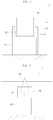
- FIG. 1 shows a front view of a wave power generation apparatus in accordance with an embodiment of the present invention
- FIG. 2 shows a side view of the wave power generation apparatus in accordance with the embodiment of the present invention
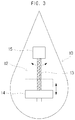
- FIG. 3 is a brief illustration of an inside of the wave power generation apparatus in accordance with the embodiment of the present invention.
- a wave power generation apparatus 1 in accordance with the present invention can include an upper structure 10, a pivot axle 11, a gravity center movement part 12, a rotation axle 13, a weight 14, a lower structure 20, a generation part 22 and a column 24.
- the wave power generation apparatus in accordance with the present invention has the upper structure 10, which is rotatably installed in the lower structure, which is installed under a water plane.
- the water plane refers to a surface of seawater
- the lower structure 20 can be installed while being submerged in the seawater.
- the upper structure 10 has either side thereof fixed by the lower structure 20 to restrict rotation in a latitudinal direction but to allow vertical rolling in a longitudinal direction.
- the wave power generation apparatus 1 can be installed in the seas having a shallow depth of water, and thus the lower structure 20 can be fixed to the sea-bed.
- the wave power generation apparatus 1 can float on the water and thus can further include a support member for keeping the wave power generation apparatus 1 at a predetermined height.
- the wave power generation apparatus 1 can be moored at a particular height by various types of support members according to the depth of the sea in which the wave power generation apparatus 1 is installed.
- the wave power generation apparatus 1 can be moored at a particular height by installing the support member underneath the lower structure 20.
- the support member can be constituted with the columns 24 that are fixed to and installed on the sea-bed.
- the columns 24 have lower parts thereof inserted and fixed to the sea-bed and have upper parts thereof coupled to one side of the lower structure 20 so as to support the lower structure 20.
- the columns24 can be formed as a fixed-type structure in the form of steel pole, pipe or truss.
- the wave power generation apparatus 1 has the lower structure 20 that is fixed and installed at a particular height by the columns 24 installed on the sea-bed, the present invention is not restricted to what is described in the present invention, and it is possible that the wave power generation apparatus 1 is installed in various forms depending on the state or depth of the sea in which the wave power generation apparatus 1 is installed.
- the support member can include at least one wire that is installed on the sea-bed and connected to the lower structure 20.
- a wire can be constituted with a single steel wire or with a tendon wire in which a plurality of steel wires are wound.
- the wire can take various other forms, such as a chain or a metal wire formed by successively coupling loops.
- the wave power generation apparatus 1 can have the upper structure 10 installed toward a direction of the wave in order to increase the vertical rolling with respect to the wave. That is, the upper structure 10 can have a front face part installed in a direction that is hit by the wave, and the vertical rolling is occurred in forward and backward directions by this wave.
- a lateral side of the upper structure 10 is narrow in an upper part and becomes increasingly wider toward a lower part.
- the lateral side of the upper structure 10 becomes increasingly narrower again below the pivot axle 11 that is supported by the lower structure 20.
- the lateral side of the upper structure 10 is formed in the shape of a roly poly or a water drop, and thus the upper structure 10 can readily have the vertical rolling in the forward and backward directions by the wave and can be readily returned to its original position.
- the upper structure 10 is formed to have a low center of gravity and has a restrained up-and-down motion. For example, when buoyancy is applied to the center of gravity by the seawater, the upper structure 10 can be positioned to be lower than the center of buoyancy.
- the wave power generation apparatus 1 can also include the generation part 22 that converts kinetic energy caused by rotary power generated when the upper structure 10 fluctuates back and forth into electrical energy.
- the generation part 22 can be installed in any one of the upper structure 10 and the lower structure 20.
- the generation part 22 can be installed on both sides of the lower structure 20, and each of driving axles thereof can be connected to an end part of the pivot axle 11 of the upper structure 10.
- the generation part 22 is installed in the lower structure, the location or number of the generation part 22 is not restricted to what is described herein and can variously modified.
- the generation part 22 can be installed inside the upper structure 10.
- the generation part 22 can be provided as a single unit that is installed on one side of the pivot axle 11 of the upper structure 10 or can be provided in two units that are respectively installed on either side of the pivot axle 11 of the upper structure 10.
- connection structure or effect thereof will be omitted herein.
- the generation part 22 is connected to the pivot axle 11 of the upper structure 10 so that rotary motion can be directly transferred, and an accelerator/decelerator (not shown) can be further installed in between the pivot axle 11 of the upper structure 10 and the driving axle of the generation part 22.
- the accelerator/decelerator amplifies the rotary motion of the upper structure 10 and transfers the rotary motion to the driving axle of the generation part 22, and accordingly the power generation efficiency can be further increased.
- the wave power generation apparatus 1 of the present invention can include a gravity center movement part 12 that moves the center of gravity of the upper structure 10.
- a gravity center movement part 12 can resonate a vertical rolling period of the upper structure 10 with a wave period, and accordingly, the upper structure 10 can roll greatly even with small-size waves.
- electricity can be stably produced by resonating the vertical rolling period of the upper structure 10 with the wave period. That is, in the case that the wave is calm (i.e., the wave period is short), the vertical rolling of the upper structure 10 can be increased, even with a small force of the wave, by moving the center of gravity of the upper structure 10 close to the center of buoyancy. Moreover, in the case that the wave is big (i.e., the wave period is long), the vertical rolling of the upper structure 10 can be stable, despite a big force of the wave, by moving the center of gravity of the upper structure 10 far away from the center of buoyancy.
- a gravity center movement part 12 can include the rotation axle 13 that is installed longitudinally in the upper structure 10. Moreover, the rotation axle 13 can have the weight 14 coupled to and installed on one side thereof.
- the rotation axle 13 can have a driving part 15 installed thereon so that the rotation axle 13 can be rotated to elevate and lowere the weight the driving part 15.
- the gravity center movement part 12 of the present invention can adjust the center of gravity of the upper structure 10 by elevating and lowering the weight 14.
- the rotation axle 13 can have a helix part formed on an external circumferential surface thereof.
- the weight 14 can have a hole, into which the rotation axle 13 is inserted, formed in a center portion thereof, and the hole can have a helix part, with which the helix part of the rotation axle 13 is coupled, formed on an internal circumferential surface thereof.
- the weight 14 becomes elevated or lowered along the helix part of the rotation axle 13.
- the upper structure 10 can be provided with a guide (not shown) that guides movement of the weight 14 and prevents rotation of the weight 14.
- the driving part 15 can include a motor, and a driving axle of the motor can be coupled with an end part of the rotation axle 13.
- the weight 14 of the present invention is installed to be elevated and lowered by the rotation of the driving part 15, the present invention is not restricted to what is described herein and can be modified in various forms.
- the driving axle of the motor which is the driving part 15, is connected to the rotation axle 13
- the driving axle of the motor is arranged in parallel with the rotation axle 13 to transfer the driving power indirectly.
- a driven gear is installed on one side of the rotation axle 13 and a driving gear, which is engaged with the driven gear, is installed on an end part of the driving axle to transfer the driving power.
- FIG. 4 is a perspective view briefly illustrating the upper structure of the wave power generation apparatus in accordance with the embodiment of the present invention.
- the width (L1) of the front face, to which the wave progresses can be about 20m
- the length (L2) of the lateral side, which is positioned at the water plane, which is the height of the sea, can be about 3.4m
- the draft (L3), which is the length submerged in the water can be about 14.1m.
- the displacement of this upper structure 10 can be about 2036.3 tons
- the height (L4) of the center of gravity (C) can be located at about 3.1m above the bottom.
- the upper structure 10 can have the height (L5) of the metacenter, which is the center of buoyancy, which determines the force of restitution of vertical rolling, at about 3.33m above the bottom.
- the above-described upper structure 10 can vertically roll within the radius of inertia of about 4m.
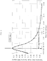
- FIG. 5 is a graph illustrating response amplitude operators (RAO) based on a wave period of the upper structure 10 in accordance with the embodiment of the present invention
- FIG. 6 is a graph illustrating a motion response of the upper structure 10 in accordance with the embodiment of the present invention for an actual state of the sea.
- RAO response amplitude operators
- the period by which the upper structure 10 rolls vertically can be made to 5 to 8 seconds, which is the wave period of the sea, by adjusting the gravity center movement part 12.
- the response amplitude operators are values indicating angles of vertical rolling of the floating body for each wave periods, when a wave with amplitude of 1m is encountered.
- response amplitude operators (RAO) of the upper structure 10 with respect to wave periods can be illustrated as shown in FIG. 5 .
- the x-axis indicates the wave periods
- the y-axis indicates responses of the floating body for each wave periods.
- the upper structure 10 can be made to resonate at the period of 6.5 seconds, which is the wave period, by adjusting the gravity center movement part 12. Accordingly, the upper structure 10 can vertically roll at the period of about 6.5 seconds.
- the upper structure 10 has vertical rolling motions having the amplitude of about 6.5 degrees when the wave having amplitude of 1m is encountered.
- the upper structure 10 has excessive vertical rolling motions between about 10 degrees and about 20 degrees, depending on the state of the sea, and excessive motion above motion response that can be directly obtained in actual wave energy can be obtained by placing a resonance point of the upper structure 10 near the wave period. Moreover, by moving the center of gravity of the upper structure 10 up and down, the vertical rolling period of the upper structure 10 can be made to match with the wave period. Accordingly, a maximum motion can be realized based on each state of the sea.
- the upper structure 10 is formed in the shape of a roly poly or a water drop
- the present invention is not restricted to what is described herein, and the upper structure 10 can be formed in various shaped that can resonate the vertical rolling period of the upper structure 10 with the wave period of the state of the sea.
- the upper structure 10 can be formed in the shape of a triangle, a gourd or any variety of shapes that increases the volume thereof below the water plane toward the bottom.
- the longitudinal length of the front face of the upper structure 10 that is encountered by the wave can be elongated in order to receive greater wave power, and it is also possible that the upper structure is formed in such a way that the top view of the upper structure 10 has a bent shape in forward and backward directions or an arc shape.
- the longitudinal length of the upper structure 10 can be designed differently by considering structural strength or manufacture.
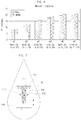
- FIG. 7 is a brief illustration of an inside of a wave power generation apparatus 1 in accordance with another embodiment of the present invention
- a gravity center movement part 112 can include a rotation axle 113 that is vertically installed in the upper structure 10.
- the rotation axle 113 can have a helix part formed on an external circumferential surface thereof.
- the rotation axle 113 can have a weight 114 installed on an end part thereof.
- the rotation axle 113 can have a driving part 116 connected thereto.
- the driving part 116 can include a motor, and a turning gear 115, which is engaged with the helix part of the rotation axle 113, can be installed on a driving axle of the motor.
- the turning gear 115 is rotated, and the rotation axle 113 engaged with the turning gear 115 is rotated. Then, due to the rotation, the rotation axle 113 moves up and down inside the upper structure 10.
- the weight 114 installed on the end part of the rotation axle 113 moves up and down due to the upward and downward movement of the rotation axle 113, and thus the center of gravity of the upper structure 10 can be adjusted.
- FIG. 8 is a brief illustration of an inside of a wave power generation apparatus 1 in accordance with yet another embodiment of the present invention
- a gravity center movement part 212 can include a rod 213 that is vertically installed in the upper structure 10 and has a gear part formed on one side thereof.
- the rod 213 can have a weight 214 installed on the other side thereof.
- the rod 213 can have a turning gear 215, which is engaged with the gear part, installed in the gear part thereof.
- the turning gear 215 receives driving power from a motor (not shown), and the weight 214 can be elevated and lowered by moving the rod 213 by the driving power. Accordingly, the center of gravity of the upper structure can be adjusted.
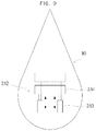
- FIG. 9 is a brief illustration of an inside of a wave power generation apparatus 1 in accordance with an unclaimed embodiment of the present invention.
- a gravity center movement part 312 of the present embodiment can include an actuator 313 inside the upper structure 10.
- the actuator 313 can be provided in a single unit or in plurality and can have a weight 314 installed on one side thereof.
- the weight 314 is elevated and lowered by operation of the actuator 313, and thus the center of gravity of the upper structure 10 can be adjusted.
- the gravity center movement part can be modified to various other forms than what are described in the above-described embodiments, and it is also possible to combine one or more of the above-described embodiments. Moreover, it is also possible to install a ballast tank inside the upper structure for the gravity center movement part and include a ballast pump that supplies or discharges ballast water by being connected with the ballast tank.
- ballast tank and the ballast pump can be additionally installed so as not to interfere with the gravity center movement part of the above-described embodiments.
- the vertical rolling of the upper structure can be made to resonate with the wave period, and thus the power generation efficiency can be improved by increasing the amount of rotation of the upper structure.
Landscapes
- Engineering & Computer Science (AREA)
- Chemical & Material Sciences (AREA)
- Combustion & Propulsion (AREA)
- Mechanical Engineering (AREA)
- General Engineering & Computer Science (AREA)
- Other Liquid Machine Or Engine Such As Wave Power Use (AREA)
Claims (8)
- Vorrichtung zur Wellenenergie-Erzeugung, die Folgendes umfasst:eine obere Struktur (10), die einen vorderen Flächenabschnitt davon aufweist, der in einer Richtung installiert ist, die von einer Welle getroffen wird, um von der Welle überrollt zu werden und eine Innenseite aufweist;eine untere Struktur (20), die unter einer Wasserebene installiert ist, um die obere Struktur drehbar zu stützen;einen Erzeugungsabschnitt (22), der auf einer von der oberen Struktur und der unteren Struktur installiert und dazu konfiguriert ist, kinetische Energie, die beim Drehen der oberen Struktur erzeugt wird, in elektrische Energie umzuwandeln; undeinen Schwerpunktbewegungsabschnitt (12, 112, 212), der in der oberen Struktur installiert und dazu konfiguriert ist, einen Schwerpunkt der oberen Struktur zu bewegen, um eine Wellenperiode und eine Rollperiode der oberen Struktur anzupassen,wobei der Schwerpunktbewegungsabschnitt (12, 112, 212) Folgendes umfasst: eine Drehachse (13, 113, 213), die längs in der oberen Struktur installiert ist; ein Gewicht (14, 114, 214), das an eine Seite der Drehachse gekoppelt ist, um angehoben und abgesenkt zu werden, wenn sich die Drehachse dreht; und einen Antriebsabschnitt (15, 115, 215), der dazu konfiguriert ist, das Gewicht durch Drehen der Drehachse anzuheben und abzusenken, und wobei der Schwerpunkt der oberen Struktur durch das Aufwärts- und/oder das Abwärtsbewegen des Gewichts in der oberen Struktur verändert wird.
- Vorrichtung zur Wellenenergie-Erzeugung (1) nach Anspruch 1, wobei eine Antriebsachse des Erzeugungsabschnitts (22) mit einer Schwenkachse der oberen Struktur (10) verbunden ist.
- Vorrichtung zur Wellenenergie-Erzeugung (1) nach Anspruch 2, ferner umfassend einen Beschleuniger/Verzögerer, der zwischen der Schwenkachse der oberen Struktur (10) und der Antriebsachse des Erzeugungsabschnitts (22) installiert ist.
- Vorrichtung zur Wellenenergie-Erzeugung (1) nach Anspruch 1, wobei der Schwerpunkt der oberen Struktur (10) tiefer positioniert ist als ein Auftriebspunkt der oberen Struktur (10) .
- Vorrichtung zur Wellenenergie-Erzeugung (1) nach Anspruch 1, wobei eine laterale Seite der oberen Struktur (10) in der Form eines Wassertropfens gebildet ist, bei dem eine Breite in Richtung eines Bodens davon zunimmt und unterhalb einer Schwenkachse der oberen Struktur (10) wieder abnimmt.
- Vorrichtung zur Wellenenergie-Erzeugung (1) nach Anspruch 1 bis 5, ferner umfassend ein Stützelement zum Halten der Vorrichtung zur Wellenenergie-Erzeugung (1) in einer vorbestimmten Höhe über der Wasserebene.
- Vorrichtung zur Wellenenergie-Erzeugung (1) nach Anspruch 6, wobei das Stützelement mindestens einen Draht umfasst, der auf einem Meeresboden installiert und mit der unteren Struktur verbunden ist.
- Vorrichtung zur Wellenenergie-Erzeugung (1) nach Anspruch 7, wobei das Stützelement eine Säule umfasst, die an dem Meeresbunden befestigt und auf diesem installiert und auf der unteren Struktur installiert ist.
Applications Claiming Priority (2)
| Application Number | Priority Date | Filing Date | Title |
|---|---|---|---|
| KR20100070519 | 2010-07-21 | ||
| PCT/KR2011/000009 WO2012011645A1 (ko) | 2010-07-21 | 2011-01-03 | 파력발전장치 |
Publications (3)
| Publication Number | Publication Date |
|---|---|
| EP2597299A1 EP2597299A1 (de) | 2013-05-29 |
| EP2597299A4 EP2597299A4 (de) | 2017-08-02 |
| EP2597299B1 true EP2597299B1 (de) | 2020-04-22 |
Family
ID=45497039
Family Applications (1)
| Application Number | Title | Priority Date | Filing Date |
|---|---|---|---|
| EP11809772.4A Active EP2597299B1 (de) | 2010-07-21 | 2011-01-03 | Vorrichtung zur wellenenergie-erzeugung |
Country Status (6)
| Country | Link |
|---|---|
| US (1) | US20130104538A1 (de) |
| EP (1) | EP2597299B1 (de) |
| JP (1) | JP5612764B2 (de) |
| KR (1) | KR101225142B1 (de) |
| DK (1) | DK2597299T3 (de) |
| WO (1) | WO2012011645A1 (de) |
Families Citing this family (11)
| Publication number | Priority date | Publication date | Assignee | Title |
|---|---|---|---|---|
| GB2512110B (en) * | 2013-03-21 | 2019-07-10 | Elogab O | A wave energy conversion system |
| EP2981705B1 (de) * | 2013-04-05 | 2018-08-01 | AW-Energy Oy | Tauchfähige wellenenergieumwandlungseinheit |
| CN105378268A (zh) * | 2013-07-12 | 2016-03-02 | 米内斯图股份公司 | 用于电力设备的机翼和涡轮机构造 |
| KR20160143756A (ko) | 2014-04-09 | 2016-12-14 | 브라임스 에너지 인코포레이티드 | 파 에너지 전환 시스템 |
| KR101850714B1 (ko) * | 2016-03-23 | 2018-04-23 | 전자부품연구원 | 최대 출력 추종을 위한 능동 위상 제어 방법 및 이를 지원하는 파력 발전 시스템 |
| EA037848B1 (ru) | 2016-07-14 | 2021-05-27 | Общество С Ограниченной Ответственностью "Биохимический Агент" | Гибридный белок, полинуклеотид, генетическая конструкция, продуцент, препарат для регенерации хряща (варианты) |
| CN109973288B (zh) * | 2019-01-31 | 2020-07-10 | 武汉大学 | 主动共振c式浮力摆波浪能发电装置 |
| CN112963292B (zh) * | 2021-03-10 | 2021-08-10 | 海南电网有限责任公司电力科学研究院 | 一种鹰式波浪能发电模拟装置 |
| KR20230126254A (ko) * | 2022-02-21 | 2023-08-30 | 현대자동차주식회사 | 재생에너지 발전시스템 |
| CN114992034B (zh) * | 2022-06-21 | 2024-08-30 | 中国电建集团华东勘测设计研究院有限公司 | 基于多时间尺度综合查询的波浪能最大功率点跟踪方法 |
| KR102739818B1 (ko) * | 2023-06-20 | 2024-12-16 | 최지유 | 윌버포스 진자를 이용한 파력발전장치 |
Family Cites Families (22)
| Publication number | Priority date | Publication date | Assignee | Title |
|---|---|---|---|---|
| US3928967A (en) * | 1973-11-15 | 1975-12-30 | Stephen Hugh Salter | Apparatus and method for extracting wave energy |
| US4189918A (en) * | 1978-08-14 | 1980-02-26 | The Secretary Of State For Energy In Her Britannic Majesty's Government Of The United Kingdom Of Great Britain And Northern Ireland | Devices for extracting energy from wave power |
| JPS56110573A (en) * | 1980-02-05 | 1981-09-01 | Shii Enajii Asooshieitsu Ltd | Floating device |
| US4497173A (en) * | 1984-04-04 | 1985-02-05 | James Gillilan | Power transducer system |
| JPS63243544A (ja) * | 1987-03-27 | 1988-10-11 | Nkk Corp | 動吸振器の制御装置 |
| JPH068767U (ja) * | 1992-06-30 | 1994-02-04 | 株式会社緑星社 | 波力発電ブイ |
| JP3107733B2 (ja) * | 1995-08-08 | 2000-11-13 | 日立造船株式会社 | 制振装置の設計方法 |
| JP2000245133A (ja) * | 1999-02-19 | 2000-09-08 | Hitachi Zosen Corp | 波力発電装置 |
| JP2002285946A (ja) | 2001-03-27 | 2002-10-03 | Shozo Nanba | 波力発電装置 |
| JP2003206845A (ja) * | 2002-01-15 | 2003-07-25 | Kajima Corp | 波力エネルギ変換装置 |
| US7042112B2 (en) * | 2004-02-03 | 2006-05-09 | Seawood Designs Inc. | Wave energy conversion system |
| JP4613649B2 (ja) | 2005-02-16 | 2011-01-19 | 哲彦 藤里 | 重力波浪発電装置 |
| GB0507366D0 (en) * | 2005-04-12 | 2005-05-18 | Green Cat Renewables Ltd | Turbine |
| US8701403B2 (en) * | 2005-11-07 | 2014-04-22 | Gwave Llc | System for producing energy through the action of waves |
| JP2007132336A (ja) | 2006-03-30 | 2007-05-31 | Sei Hybrid Kk | 波力発電装置 |
| KR200435775Y1 (ko) | 2006-09-08 | 2007-02-16 | 서문춘 | 완구용 회전팽이 |
| NZ551485A (en) * | 2006-11-21 | 2009-06-26 | Ind Res Ltd | Wave energy converter |
| JP2008168980A (ja) * | 2007-01-10 | 2008-07-24 | Hitachi Ltd | エレベータ乗りかごの縦振動抑制装置 |
| US7703562B2 (en) * | 2007-05-25 | 2010-04-27 | Toyota Motor Engineering & Manufacturing North America, Inc. | Energy efficient robotic system |
| KR100945754B1 (ko) * | 2008-05-26 | 2010-03-08 | 동방엔지니어링 주식회사 | 조력을 이용한 발전장치 |
| US7765804B2 (en) * | 2008-06-03 | 2010-08-03 | Davis Stephen E | Hydraulic motor using buoyant and gravitational forces to generate kinetic energy |
| FI124961B (fi) * | 2008-10-10 | 2015-04-15 | Wello Oy | Aaltovoimala |
-
2011
- 2011-01-03 EP EP11809772.4A patent/EP2597299B1/de active Active
- 2011-01-03 WO PCT/KR2011/000009 patent/WO2012011645A1/ko not_active Ceased
- 2011-01-03 JP JP2013516488A patent/JP5612764B2/ja active Active
- 2011-01-03 DK DK11809772.4T patent/DK2597299T3/da active
- 2011-01-03 US US13/807,213 patent/US20130104538A1/en not_active Abandoned
- 2011-04-06 KR KR1020110031500A patent/KR101225142B1/ko not_active Expired - Fee Related
Non-Patent Citations (1)
| Title |
|---|
| None * |
Also Published As
| Publication number | Publication date |
|---|---|
| KR101225142B1 (ko) | 2013-01-22 |
| JP2013533419A (ja) | 2013-08-22 |
| JP5612764B2 (ja) | 2014-10-22 |
| US20130104538A1 (en) | 2013-05-02 |
| DK2597299T3 (da) | 2020-05-04 |
| EP2597299A4 (de) | 2017-08-02 |
| KR20120010101A (ko) | 2012-02-02 |
| EP2597299A1 (de) | 2013-05-29 |
| WO2012011645A1 (ko) | 2012-01-26 |
Similar Documents
| Publication | Publication Date | Title |
|---|---|---|
| EP2597299B1 (de) | Vorrichtung zur wellenenergie-erzeugung | |
| CN109026512B (zh) | 一种减少阻力的风能、海洋能综合发电装置 | |
| US9062649B2 (en) | Device for conversion of mechanical energy from sea waves to electric energy | |
| EP2318699B1 (de) | Verbesserte energiegewinnung aus meereswellen | |
| KR102165167B1 (ko) | 부유식 풍력발전 시스템 | |
| CN102168642B (zh) | 振荡式潮流发电装置 | |
| KR101620900B1 (ko) | 조류 순응형 해상 부유식 풍력발전장치 | |
| CN116873140B (zh) | 集防浪消波和海洋能发电于一体的浮式平台及其工作方法 | |
| US20240295208A1 (en) | Energy converter for ocean waves and method for using thereof | |
| WO2010080045A1 (en) | Device for generating energy from the motion of sea waves | |
| CN115009451A (zh) | 一种半潜式能源浮岛发电装置 | |
| GB2542548A (en) | System and method | |
| CN109026514A (zh) | 一种降低发电过程阻碍作用的海洋能发电装置 | |
| CN101922403A (zh) | 波浪能发电系统 | |
| CN114940238A (zh) | 一种海上浮式平台系泊结构 | |
| CN214533359U (zh) | 一种基于漂浮式平台的风浪耦合利用装置 | |
| KR102755503B1 (ko) | 대용량 해상 풍력 터빈의 설치 시스템 | |
| JP2004019470A (ja) | 浮体式大型風力発電装置 | |
| CN102297069B (zh) | 风光互补波浪发电站 | |
| KR101315180B1 (ko) | 떠 있는 연속풍력발전장치 | |
| CN119221416B (zh) | 一种用于海上光伏发电的消波装置 | |
| CN118008713A (zh) | 一种无塔筒漂浮式海上垂直轴风机装置及抗海浪冲击方法 | |
| CN111319726A (zh) | 一种多种发电方式小型半潜平台 | |
| KR20150076704A (ko) | 수력 터빈 방파 장치 및 그 수력 터빈 방파 장치를 이용한 파랑 하중 감쇄 시스템 | |
| KR20130048852A (ko) | 부유식 해상 풍력발전장치 |
Legal Events
| Date | Code | Title | Description |
|---|---|---|---|
| PUAI | Public reference made under article 153(3) epc to a published international application that has entered the european phase |
Free format text: ORIGINAL CODE: 0009012 |
|
| 17P | Request for examination filed |
Effective date: 20130221 |
|
| AK | Designated contracting states |
Kind code of ref document: A1 Designated state(s): AL AT BE BG CH CY CZ DE DK EE ES FI FR GB GR HR HU IE IS IT LI LT LU LV MC MK MT NL NO PL PT RO RS SE SI SK SM TR |
|
| DAX | Request for extension of the european patent (deleted) | ||
| RA4 | Supplementary search report drawn up and despatched (corrected) |
Effective date: 20170703 |
|
| RIC1 | Information provided on ipc code assigned before grant |
Ipc: F03B 13/14 20060101ALI20170627BHEP Ipc: F03B 13/22 20060101ALI20170627BHEP Ipc: F03B 13/18 20060101AFI20170627BHEP |
|
| STAA | Information on the status of an ep patent application or granted ep patent |
Free format text: STATUS: EXAMINATION IS IN PROGRESS |
|
| 17Q | First examination report despatched |
Effective date: 20181210 |
|
| GRAP | Despatch of communication of intention to grant a patent |
Free format text: ORIGINAL CODE: EPIDOSNIGR1 |
|
| STAA | Information on the status of an ep patent application or granted ep patent |
Free format text: STATUS: GRANT OF PATENT IS INTENDED |
|
| INTG | Intention to grant announced |
Effective date: 20191218 |
|
| GRAS | Grant fee paid |
Free format text: ORIGINAL CODE: EPIDOSNIGR3 |
|
| GRAA | (expected) grant |
Free format text: ORIGINAL CODE: 0009210 |
|
| STAA | Information on the status of an ep patent application or granted ep patent |
Free format text: STATUS: THE PATENT HAS BEEN GRANTED |
|
| AK | Designated contracting states |
Kind code of ref document: B1 Designated state(s): AL AT BE BG CH CY CZ DE DK EE ES FI FR GB GR HR HU IE IS IT LI LT LU LV MC MK MT NL NO PL PT RO RS SE SI SK SM TR |
|
| REG | Reference to a national code |
Ref country code: GB Ref legal event code: FG4D |
|
| REG | Reference to a national code |
Ref country code: CH Ref legal event code: EP |
|
| REG | Reference to a national code |
Ref country code: DK Ref legal event code: T3 Effective date: 20200428 |
|
| REG | Reference to a national code |
Ref country code: IE Ref legal event code: FG4D |
|
| REG | Reference to a national code |
Ref country code: DE Ref legal event code: R096 Ref document number: 602011066419 Country of ref document: DE |
|
| REG | Reference to a national code |
Ref country code: AT Ref legal event code: REF Ref document number: 1260417 Country of ref document: AT Kind code of ref document: T Effective date: 20200515 |
|
| REG | Reference to a national code |
Ref country code: LT Ref legal event code: MG4D |
|
| REG | Reference to a national code |
Ref country code: NL Ref legal event code: MP Effective date: 20200422 |
|
| PG25 | Lapsed in a contracting state [announced via postgrant information from national office to epo] |
Ref country code: NO Free format text: LAPSE BECAUSE OF FAILURE TO SUBMIT A TRANSLATION OF THE DESCRIPTION OR TO PAY THE FEE WITHIN THE PRESCRIBED TIME-LIMIT Effective date: 20200722 Ref country code: GR Free format text: LAPSE BECAUSE OF FAILURE TO SUBMIT A TRANSLATION OF THE DESCRIPTION OR TO PAY THE FEE WITHIN THE PRESCRIBED TIME-LIMIT Effective date: 20200723 Ref country code: LT Free format text: LAPSE BECAUSE OF FAILURE TO SUBMIT A TRANSLATION OF THE DESCRIPTION OR TO PAY THE FEE WITHIN THE PRESCRIBED TIME-LIMIT Effective date: 20200422 Ref country code: SE Free format text: LAPSE BECAUSE OF FAILURE TO SUBMIT A TRANSLATION OF THE DESCRIPTION OR TO PAY THE FEE WITHIN THE PRESCRIBED TIME-LIMIT Effective date: 20200422 Ref country code: NL Free format text: LAPSE BECAUSE OF FAILURE TO SUBMIT A TRANSLATION OF THE DESCRIPTION OR TO PAY THE FEE WITHIN THE PRESCRIBED TIME-LIMIT Effective date: 20200422 Ref country code: PT Free format text: LAPSE BECAUSE OF FAILURE TO SUBMIT A TRANSLATION OF THE DESCRIPTION OR TO PAY THE FEE WITHIN THE PRESCRIBED TIME-LIMIT Effective date: 20200824 Ref country code: FI Free format text: LAPSE BECAUSE OF FAILURE TO SUBMIT A TRANSLATION OF THE DESCRIPTION OR TO PAY THE FEE WITHIN THE PRESCRIBED TIME-LIMIT Effective date: 20200422 Ref country code: IS Free format text: LAPSE BECAUSE OF FAILURE TO SUBMIT A TRANSLATION OF THE DESCRIPTION OR TO PAY THE FEE WITHIN THE PRESCRIBED TIME-LIMIT Effective date: 20200822 |
|
| REG | Reference to a national code |
Ref country code: AT Ref legal event code: MK05 Ref document number: 1260417 Country of ref document: AT Kind code of ref document: T Effective date: 20200422 |
|
| PG25 | Lapsed in a contracting state [announced via postgrant information from national office to epo] |
Ref country code: HR Free format text: LAPSE BECAUSE OF FAILURE TO SUBMIT A TRANSLATION OF THE DESCRIPTION OR TO PAY THE FEE WITHIN THE PRESCRIBED TIME-LIMIT Effective date: 20200422 Ref country code: LV Free format text: LAPSE BECAUSE OF FAILURE TO SUBMIT A TRANSLATION OF THE DESCRIPTION OR TO PAY THE FEE WITHIN THE PRESCRIBED TIME-LIMIT Effective date: 20200422 Ref country code: RS Free format text: LAPSE BECAUSE OF FAILURE TO SUBMIT A TRANSLATION OF THE DESCRIPTION OR TO PAY THE FEE WITHIN THE PRESCRIBED TIME-LIMIT Effective date: 20200422 Ref country code: BG Free format text: LAPSE BECAUSE OF FAILURE TO SUBMIT A TRANSLATION OF THE DESCRIPTION OR TO PAY THE FEE WITHIN THE PRESCRIBED TIME-LIMIT Effective date: 20200722 |
|
| PG25 | Lapsed in a contracting state [announced via postgrant information from national office to epo] |
Ref country code: AL Free format text: LAPSE BECAUSE OF FAILURE TO SUBMIT A TRANSLATION OF THE DESCRIPTION OR TO PAY THE FEE WITHIN THE PRESCRIBED TIME-LIMIT Effective date: 20200422 |
|
| REG | Reference to a national code |
Ref country code: DE Ref legal event code: R097 Ref document number: 602011066419 Country of ref document: DE |
|
| PG25 | Lapsed in a contracting state [announced via postgrant information from national office to epo] |
Ref country code: RO Free format text: LAPSE BECAUSE OF FAILURE TO SUBMIT A TRANSLATION OF THE DESCRIPTION OR TO PAY THE FEE WITHIN THE PRESCRIBED TIME-LIMIT Effective date: 20200422 Ref country code: IT Free format text: LAPSE BECAUSE OF FAILURE TO SUBMIT A TRANSLATION OF THE DESCRIPTION OR TO PAY THE FEE WITHIN THE PRESCRIBED TIME-LIMIT Effective date: 20200422 Ref country code: CZ Free format text: LAPSE BECAUSE OF FAILURE TO SUBMIT A TRANSLATION OF THE DESCRIPTION OR TO PAY THE FEE WITHIN THE PRESCRIBED TIME-LIMIT Effective date: 20200422 Ref country code: EE Free format text: LAPSE BECAUSE OF FAILURE TO SUBMIT A TRANSLATION OF THE DESCRIPTION OR TO PAY THE FEE WITHIN THE PRESCRIBED TIME-LIMIT Effective date: 20200422 Ref country code: SM Free format text: LAPSE BECAUSE OF FAILURE TO SUBMIT A TRANSLATION OF THE DESCRIPTION OR TO PAY THE FEE WITHIN THE PRESCRIBED TIME-LIMIT Effective date: 20200422 Ref country code: ES Free format text: LAPSE BECAUSE OF FAILURE TO SUBMIT A TRANSLATION OF THE DESCRIPTION OR TO PAY THE FEE WITHIN THE PRESCRIBED TIME-LIMIT Effective date: 20200422 Ref country code: AT Free format text: LAPSE BECAUSE OF FAILURE TO SUBMIT A TRANSLATION OF THE DESCRIPTION OR TO PAY THE FEE WITHIN THE PRESCRIBED TIME-LIMIT Effective date: 20200422 |
|
| PG25 | Lapsed in a contracting state [announced via postgrant information from national office to epo] |
Ref country code: SK Free format text: LAPSE BECAUSE OF FAILURE TO SUBMIT A TRANSLATION OF THE DESCRIPTION OR TO PAY THE FEE WITHIN THE PRESCRIBED TIME-LIMIT Effective date: 20200422 Ref country code: PL Free format text: LAPSE BECAUSE OF FAILURE TO SUBMIT A TRANSLATION OF THE DESCRIPTION OR TO PAY THE FEE WITHIN THE PRESCRIBED TIME-LIMIT Effective date: 20200422 |
|
| PLBE | No opposition filed within time limit |
Free format text: ORIGINAL CODE: 0009261 |
|
| STAA | Information on the status of an ep patent application or granted ep patent |
Free format text: STATUS: NO OPPOSITION FILED WITHIN TIME LIMIT |
|
| 26N | No opposition filed |
Effective date: 20210125 |
|
| PG25 | Lapsed in a contracting state [announced via postgrant information from national office to epo] |
Ref country code: SI Free format text: LAPSE BECAUSE OF FAILURE TO SUBMIT A TRANSLATION OF THE DESCRIPTION OR TO PAY THE FEE WITHIN THE PRESCRIBED TIME-LIMIT Effective date: 20200422 |
|
| REG | Reference to a national code |
Ref country code: DE Ref legal event code: R119 Ref document number: 602011066419 Country of ref document: DE |
|
| PG25 | Lapsed in a contracting state [announced via postgrant information from national office to epo] |
Ref country code: MC Free format text: LAPSE BECAUSE OF FAILURE TO SUBMIT A TRANSLATION OF THE DESCRIPTION OR TO PAY THE FEE WITHIN THE PRESCRIBED TIME-LIMIT Effective date: 20200422 |
|
| REG | Reference to a national code |
Ref country code: CH Ref legal event code: PL |
|
| GBPC | Gb: european patent ceased through non-payment of renewal fee |
Effective date: 20210103 |
|
| PG25 | Lapsed in a contracting state [announced via postgrant information from national office to epo] |
Ref country code: LU Free format text: LAPSE BECAUSE OF NON-PAYMENT OF DUE FEES Effective date: 20210103 |
|
| REG | Reference to a national code |
Ref country code: BE Ref legal event code: MM Effective date: 20210131 |
|
| PG25 | Lapsed in a contracting state [announced via postgrant information from national office to epo] |
Ref country code: GB Free format text: LAPSE BECAUSE OF NON-PAYMENT OF DUE FEES Effective date: 20210103 Ref country code: DE Free format text: LAPSE BECAUSE OF NON-PAYMENT OF DUE FEES Effective date: 20210803 Ref country code: CH Free format text: LAPSE BECAUSE OF NON-PAYMENT OF DUE FEES Effective date: 20210131 Ref country code: LI Free format text: LAPSE BECAUSE OF NON-PAYMENT OF DUE FEES Effective date: 20210131 |
|
| PG25 | Lapsed in a contracting state [announced via postgrant information from national office to epo] |
Ref country code: IE Free format text: LAPSE BECAUSE OF NON-PAYMENT OF DUE FEES Effective date: 20210103 |
|
| PG25 | Lapsed in a contracting state [announced via postgrant information from national office to epo] |
Ref country code: BE Free format text: LAPSE BECAUSE OF NON-PAYMENT OF DUE FEES Effective date: 20210131 |
|
| PG25 | Lapsed in a contracting state [announced via postgrant information from national office to epo] |
Ref country code: HU Free format text: LAPSE BECAUSE OF FAILURE TO SUBMIT A TRANSLATION OF THE DESCRIPTION OR TO PAY THE FEE WITHIN THE PRESCRIBED TIME-LIMIT; INVALID AB INITIO Effective date: 20110103 Ref country code: CY Free format text: LAPSE BECAUSE OF FAILURE TO SUBMIT A TRANSLATION OF THE DESCRIPTION OR TO PAY THE FEE WITHIN THE PRESCRIBED TIME-LIMIT Effective date: 20200422 |
|
| PG25 | Lapsed in a contracting state [announced via postgrant information from national office to epo] |
Ref country code: MK Free format text: LAPSE BECAUSE OF FAILURE TO SUBMIT A TRANSLATION OF THE DESCRIPTION OR TO PAY THE FEE WITHIN THE PRESCRIBED TIME-LIMIT Effective date: 20200422 |
|
| PG25 | Lapsed in a contracting state [announced via postgrant information from national office to epo] |
Ref country code: TR Free format text: LAPSE BECAUSE OF FAILURE TO SUBMIT A TRANSLATION OF THE DESCRIPTION OR TO PAY THE FEE WITHIN THE PRESCRIBED TIME-LIMIT Effective date: 20200422 |
|
| PG25 | Lapsed in a contracting state [announced via postgrant information from national office to epo] |
Ref country code: MT Free format text: LAPSE BECAUSE OF FAILURE TO SUBMIT A TRANSLATION OF THE DESCRIPTION OR TO PAY THE FEE WITHIN THE PRESCRIBED TIME-LIMIT Effective date: 20200422 |
|
| PGFP | Annual fee paid to national office [announced via postgrant information from national office to epo] |
Ref country code: FR Payment date: 20241209 Year of fee payment: 15 |
|
| PGFP | Annual fee paid to national office [announced via postgrant information from national office to epo] |
Ref country code: DK Payment date: 20250113 Year of fee payment: 15 |