EP2597293A2 - Rocket stage with liquid propulsion system - Google Patents
Rocket stage with liquid propulsion system Download PDFInfo
- Publication number
- EP2597293A2 EP2597293A2 EP12006377.1A EP12006377A EP2597293A2 EP 2597293 A2 EP2597293 A2 EP 2597293A2 EP 12006377 A EP12006377 A EP 12006377A EP 2597293 A2 EP2597293 A2 EP 2597293A2
- Authority
- EP
- European Patent Office
- Prior art keywords
- tank
- engine
- rocket stage
- fuel
- stage according
- Prior art date
- Legal status (The legal status is an assumption and is not a legal conclusion. Google has not performed a legal analysis and makes no representation as to the accuracy of the status listed.)
- Granted
Links
- 239000007788 liquid Substances 0.000 title claims description 14
- 239000000446 fuel Substances 0.000 claims abstract description 27
- 239000007800 oxidant agent Substances 0.000 claims abstract description 10
- 230000002787 reinforcement Effects 0.000 claims description 2
- 230000001590 oxidative effect Effects 0.000 abstract 1
- 239000010763 heavy fuel oil Substances 0.000 description 4
- 230000010354 integration Effects 0.000 description 4
- 238000005192 partition Methods 0.000 description 4
- 230000001133 acceleration Effects 0.000 description 2
- 238000009434 installation Methods 0.000 description 2
- 238000005452 bending Methods 0.000 description 1
- 230000000694 effects Effects 0.000 description 1
- 230000002349 favourable effect Effects 0.000 description 1
- 238000010304 firing Methods 0.000 description 1
- 230000001771 impaired effect Effects 0.000 description 1
- 230000000977 initiatory effect Effects 0.000 description 1
- 238000004519 manufacturing process Methods 0.000 description 1
- 239000003380 propellant Substances 0.000 description 1
- 239000011800 void material Substances 0.000 description 1
- 239000013585 weight reducing agent Substances 0.000 description 1
Images


Classifications
-
- F—MECHANICAL ENGINEERING; LIGHTING; HEATING; WEAPONS; BLASTING
- F02—COMBUSTION ENGINES; HOT-GAS OR COMBUSTION-PRODUCT ENGINE PLANTS
- F02K—JET-PROPULSION PLANTS
- F02K9/00—Rocket-engine plants, i.e. plants carrying both fuel and oxidant therefor; Control thereof
- F02K9/42—Rocket-engine plants, i.e. plants carrying both fuel and oxidant therefor; Control thereof using liquid or gaseous propellants
- F02K9/60—Constructional parts; Details not otherwise provided for
- F02K9/605—Reservoirs
-
- B—PERFORMING OPERATIONS; TRANSPORTING
- B64—AIRCRAFT; AVIATION; COSMONAUTICS
- B64G—COSMONAUTICS; VEHICLES OR EQUIPMENT THEREFOR
- B64G1/00—Cosmonautic vehicles
- B64G1/22—Parts of, or equipment specially adapted for fitting in or to, cosmonautic vehicles
- B64G1/40—Arrangements or adaptations of propulsion systems
- B64G1/402—Propellant tanks; Feeding propellants
-
- F—MECHANICAL ENGINEERING; LIGHTING; HEATING; WEAPONS; BLASTING
- F02—COMBUSTION ENGINES; HOT-GAS OR COMBUSTION-PRODUCT ENGINE PLANTS
- F02K—JET-PROPULSION PLANTS
- F02K9/00—Rocket-engine plants, i.e. plants carrying both fuel and oxidant therefor; Control thereof
- F02K9/42—Rocket-engine plants, i.e. plants carrying both fuel and oxidant therefor; Control thereof using liquid or gaseous propellants
- F02K9/60—Constructional parts; Details not otherwise provided for
Landscapes
- Engineering & Computer Science (AREA)
- Chemical & Material Sciences (AREA)
- Combustion & Propulsion (AREA)
- Mechanical Engineering (AREA)
- General Engineering & Computer Science (AREA)
- Remote Sensing (AREA)
- Aviation & Aerospace Engineering (AREA)
- Filling Or Discharging Of Gas Storage Vessels (AREA)
- Cleaning Or Clearing Of The Surface Of Open Water (AREA)
- Testing Of Engines (AREA)
Abstract
Description
Die Erfindung betrifft eine Raketenstufe zum Betrieb von Raumflugkörpern mit wenigstens je einer Primärstruktur, einem Tank zur getrennten Lagerung von Brennstoff und Oxidator, einem Triebwerk sowie mit einem Triebwerk-Schubgerüst, das die verschiedenen Komponenten miteinander verbindet.The invention relates to a rocket stage for the operation of spacecraft with at least one each primary structure, a tank for separate storage of fuel and oxidizer, an engine and with an engine thruster, which connects the various components together.
Die derzeit verwendeten Trägerraketenstufen mit Flüssigantriebssystemen enthalten eine Reihe von Komponenten, die unterschiedliche Funktionen erfüllen. Dazu gehören Tanks zur Lagerung von Brennstoff und Oxidator, wobei der Brennstoff und der Oxidator entweder in separaten Tanks oder in einem Tank mit einer Trennwand zwischen Brennstoff und Oxidator gelagert werden, sowie ein sogenanntes Triebwerk-Schubgerüst, im Englischen als Engine Thrust Frame (ETF) bezeichnet. Letzteres leitet einerseits die Lasten des Triebwerks in den Tank und in die primäre Struktur ein und andererseits die Lasten des Trägers über die Primärstruktur in den Tank und das Triebwerk. Ferner umfassen derartige Raketenstufen Treibstoffhandhabungsgeräte, im Englischen als Propellant Management Devices (PMD) bezeichnet, die unter anderem der Sicherstellung der Versorgung des Triebwerks mit gas- und partikelfreiem Treibstoff auch bei einer minimal verbleibenden Treibstoffrestmenge oder dem Abbremsen des Dralls der Flüssigkeit dienen.Currently used launcher stages with liquid propulsion systems include a number of components that perform different functions. These include tanks for storing fuel and oxidizer, where the fuel and oxidizer are stored either in separate tanks or in a tank with a partition wall between fuel and oxidizer, as well as a so-called engine thrust frame (ETF). designated. The latter, on the one hand, introduces the loads of the engine into the tank and into the primary structure and, on the other hand, transfers the loads of the carrier via the primary structure into the tank and the engine. Furthermore, such rocket stages include fuel handling devices, in English as Propellant Management Devices (PMD) called, among other things, to ensure the supply of the engine with gas- and particle-free fuel even with a minimum residual fuel remaining or slowing down the spin of the liquid.
Aufgabe der Erfindung ist es, eine Raketenstufe der eingangs genannten Art so auszubilden, dass sie ein möglichst niedriges Gewicht und ein kompaktes Design aufweist und darüber hinaus möglichst geringe Kosten verursacht.The object of the invention is to provide a rocket stage of the type mentioned in such a way that it has the lowest possible weight and a compact design and also causes the lowest possible cost.
Die Erfindung löst diese Aufgabe, indem sie bei einer derartigen Raketenstufe vorsieht, dass wenigstens ein Teil des Triebwerk-Schubgerüstes im Inneren des Tanks angeordnet ist, wobei dieser Teil des Triebwerk-Schubgerüstes innerhalb des Tanks derart vollständig geschlossen ausgebildet ist, dass im Tank voneinander getrennte Bereiche zur Lagerung der Komponenten des Treibstoffs gebildet sind.The invention solves this problem by providing in such a rocket stage that at least a part of the engine thrust framework is arranged inside the tank, wherein this part of the engine thrust framework is formed inside the tank so completely closed that separate from each other in the tank Areas are formed for storage of the components of the fuel.
Durch die erfindungsgemäß vorgesehene Integration der ansonsten separaten Komponenten Tank und Triebwerk-Schubgerüst zu einer Einheit ergeben sich eine äußerst kompakte Anordnung und zugleich eine erhebliche Gewichtsverminderung, außerdem wird auf diese Weise auch das Gewicht der angrenzenden Strukturen entsprechend reduziert. Durch das kompakte Design ist die Gesamtlänge der erfindungsgemäßen Raketenstufe wesentlich geringer als diejenige herkömmlicher Konfigurationen, was wiederum die mechanischen Lasten, wie Windlasten und die durch die Nutzlast induzierte Lasten nachhaltig reduziert. Zudem werden durch die erfindungsgemäß vorgesehene Ausbildung der Raketenstufe nach der Erfindung die verschiedenen Funktionen optimal auf die einzelnen Komponenten verteilt. So wird das im wesentlichen konusförmige Triebwerk-Schubgerüst zugleich zur Trennung von Brennstoff und Oxidator im Tank genutzt, außerdem reduziert es die geometrischen Residuals.The inventively provided integration of the otherwise separate components tank and engine thrust to a unit results in an extremely compact arrangement and at the same time a significant weight reduction, also in this way, the weight of the adjacent structures is reduced accordingly. Due to the compact design, the overall length of the rocket stage according to the invention is substantially lower than that of conventional configurations, which in turn sustainably reduces mechanical loads such as wind loads and loads induced by the payload. In addition, the various functions are optimally distributed to the individual components by the inventively provided training of the rocket stage according to the invention. So that will be in the In addition, it reduces the geometric residuals, which are used to separate fuel and oxidizer in the tank.
Durch die in vorteilhafter Weiterbildung der Erfindung ferner vorgesehene Integration auch der Treibstoffhandhabungsgeräte wird die Kompaktheit der Anordnung noch weiter verbessert. Gleichzeitig werden die Komponenten der Treibstoffhandhabungsgeräte, wie Leitbleche und wiederbefüllbarer Flüssigkeitsbehälter, auch zur Lasteinleitung genutzt. Schließlich weist die Raketenstufe gemäß der Erfindung über die in speziellen Fällen erforderliche Wiederzündfähigkeit auf.By further provided in an advantageous embodiment of the invention also integration of the fuel handling devices, the compactness of the arrangement is further improved. At the same time the components of the fuel handling devices, such as baffles and refillable liquid container, are also used for load introduction. Finally, the rocket stage according to the invention has the required re-ignitability in special cases.
Nachfolgend soll die Erfindung anhand der Zeichnung näher erläutert werden. Es zeigen
- Fig. 1.
- einen Teil einer Raketenstufe in geschnittener Darstellung,
- Fig. 2
- eine vergrößerte Darstellung eines Teilbereiches der Anordnung gemäß
Fig. 1 , - Fig. 3
- eine andere Ansicht eines vergrößerten Teilbereiches der Anordnung gemäß
Fig. 1 , - Fig. 4
- eine abermals vergrößerte Darstellung eines Teilbereiches der Anordnung gemäß
Fig. 3 , - Fig. 5-7
- Darstellungen verschiedener Formen von Tanks für eine Raketenstufe,
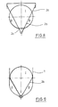
- Fig. 8 und 9
- Darstellungen alternativer Anordnungen von Triebwerk-Schubgerüsten in Tanks und
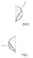
- Fig. 10 und 11
- zwei weitere Darstellungen alternativer Triebwerk-Schubgerüstform für eine Raketenstufe.
- Fig. 1.
- a part of a rocket stage in a cutaway view,
- Fig. 2
- an enlarged view of a portion of the arrangement according to
Fig. 1 . - Fig. 3
- another view of an enlarged portion of the arrangement according to
Fig. 1 . - Fig. 4
- a again enlarged view of a portion of the arrangement according to
Fig. 3 . - Fig. 5-7
- Representations of different forms of tanks for a rocket stage,
- 8 and 9
- Representations of alternative arrangements of engine pushrods in tanks and
- 10 and 11
- two more representations of alternative thruster scaffold shape for a rocket stage.
In den Figuren sind gleiche bzw. einander entsprechende Bauteile mit den gleichen Bezugszeichen versehen.In the figures, the same or corresponding components are provided with the same reference numerals.
Die Darstellung gemäß
Die Integration des konusförmigen Triebwerk-Schubgerüstes 2 in den kugelförmigen Tank 3 verleiht dem konusförmigen Triebwerk-Schubgerüst 2 zwei weitere Funktionen. So unterteilt es durch seinen im Tank 3 angeordneten, als Trennwand 2b wirkenden Teil den Tank 3 in zwei Bereiche I und II, wie insbesondere in
Die in
Die Leitbleche 5a stehen senkrecht zur Symmetrieachse der Raketenstufe und verbinden den breitesten Teil des Tanks 3 mit dem Tankauslass, um den Drall der Flüssigkeit zu bremsen und um diese zum Tankauslass zu leiten. Die wiederbefüllbaren Flüssigkeitsbehälter 5b sind oberhalb der Tankauslässe befestigt und halten eine ausreichende Flüssigkeitsmenge am Auslass, um einerseits aufgrund von Oberflächenspannungskräften die Gasfreiheit des Treibstoffs zu gewährleisten und um andererseits sicherzustellen, dass bei einer erneuten Zündung des Triebwerks 4 sofort Treibstoff zur Verfügung steht, noch bevor die Beschleunigung den Rest des Treibstoffs zum Tankauslass geführt hat. Die Leitbleche 5a und die wiederbefüllbaren Flüssigkeitsbehälter 5b sind dabei in den beiden Bereichen I und II des Tanks 3 angeordnet.The
Die vergrößerte Darstellung eines Teilbereiches der vorangehend beschriebenen Anordnung in
Die nochmals vergrößerte Darstellung eines Teilbereiches der Anordnung gemäß
Die Integration der Treibstoffhandhabungsgeräte 5 in die Anordnung unterstützt im Bereich der Auslässe des Tanks 3 das konusförmige Triebwerk-Schubgerüst 2 in seiner lasttragenden Funktion zur Einleitung der Triebwerkslasten in die Primärstruktur 1. Der Lastweg geht dabei überwiegend durch das konusförmige Triebwerk-Schubgerüst 2, so dass keine zusätzlichen Supports benötigt werden. Die Leitbleche haben ansonsten ihre kapillare Funktion, um Flüssigkeit zu binden, sie in den unteren Teil des Tanks 3 zu leiten und sie dort zu halten. Erwähnt sei, dass auch der in den
Da die Optimierung des Durchmessers und der Höhe einer Raketenstufe auch von der gesamten Trägerkonfiguration abhängt, ist es für eine Optimierung der Trägerleistung einer Raketenstufe wichtig, dass der Durchmesser und die Länge des Tanks variiert werden können. Da durch rein kugelförmige Tankdome unter Umständen relativ große Leervolumina entstehen können, in deren Folge eine Trägerstufe unnötig groß geraten kann, ist eine reine Kugelform eines derartigen Tanks nicht in allen Fällen optimal. In den
Dies kann ein Tank mit einem zylindrischen Zwischenstück 9 sein, wie er in
Bei dem im wesentlichen konusförmigen Triebwerk-Schubgerüst 2 kann die Trennwand 2b einerseits mit einem konusförmigen Ring 2a, dem sogenannten Conical Tank Attachment Ring, zur Primärstruktur 1 und andererseits mittels einer Tankverlängerung 2c zum Triebwerk 4 hin verlängert werden, wie dies in
Bei den vorstehend beschriebenen Anordnungen ist das Triebwerk-Schubgerüst konusförmig ausgebildet. Je nach der Systemanforderung kann es aber auch von dieser Form abweichen. In den
Claims (10)
Applications Claiming Priority (1)
| Application Number | Priority Date | Filing Date | Title |
|---|---|---|---|
| DE102011119921A DE102011119921B3 (en) | 2011-11-25 | 2011-11-25 | Rocket stage with liquid propellant system |
Publications (3)
| Publication Number | Publication Date |
|---|---|
| EP2597293A2 true EP2597293A2 (en) | 2013-05-29 |
| EP2597293A3 EP2597293A3 (en) | 2018-04-04 |
| EP2597293B1 EP2597293B1 (en) | 2019-05-22 |
Family
ID=46845573
Family Applications (1)
| Application Number | Title | Priority Date | Filing Date |
|---|---|---|---|
| EP12006377.1A Active EP2597293B1 (en) | 2011-11-25 | 2012-09-11 | Rocket stage with liquid propulsion system |
Country Status (9)
| Country | Link |
|---|---|
| US (1) | US9347400B2 (en) |
| EP (1) | EP2597293B1 (en) |
| JP (1) | JP6043603B2 (en) |
| CN (1) | CN103134395B (en) |
| BR (1) | BR102012029981B1 (en) |
| DE (1) | DE102011119921B3 (en) |
| ES (1) | ES2740006T3 (en) |
| RU (1) | RU2628272C2 (en) |
| UA (1) | UA116870C2 (en) |
Families Citing this family (10)
| Publication number | Priority date | Publication date | Assignee | Title |
|---|---|---|---|---|
| EP2769918A1 (en) * | 2013-02-26 | 2014-08-27 | Astrium Limited | Detecting propellant levels in spacecraft |
| US20150151855A1 (en) * | 2013-08-28 | 2015-06-04 | Moon Express, Inc. | System and method for multi-role planetary lander and ascent spacecraft |
| CN104712461A (en) * | 2013-12-12 | 2015-06-17 | 葛泓杉 | Liquid-level-collapse preventing floating plate |
| US9970389B2 (en) * | 2014-03-06 | 2018-05-15 | The Boeing Company | Antivortex device and method of assembling thereof |
| CN106837606A (en) * | 2017-03-30 | 2017-06-13 | 哈尔滨工业大学 | A kind of integral composite material tank structure |
| US11027859B2 (en) * | 2017-10-16 | 2021-06-08 | The Boeing Company | Variable stiffness flyer plate for penetration device |
| US20190112076A1 (en) * | 2017-10-16 | 2019-04-18 | The Boeing Company | Variable thickness flyer plate for penetration device |
| CN107975441A (en) * | 2017-11-24 | 2018-05-01 | 神州五行航天科技有限公司 | A kind of carrier rocket/Missile Tank with longitudinal baffle |
| EP3584175B1 (en) * | 2018-06-15 | 2023-03-29 | ArianeGroup GmbH | Spacecraft and method of use of at least one secondary structure in a spacecraft |
| CN110510128B (en) * | 2019-08-02 | 2021-04-20 | 宁波天擎航天科技有限公司 | Propulsion system |
Family Cites Families (18)
| Publication number | Priority date | Publication date | Assignee | Title |
|---|---|---|---|---|
| US2902822A (en) * | 1954-02-23 | 1959-09-08 | James D Mckiernan | Container structure for separate storage of liquid rocket propellants |
| US3246394A (en) * | 1960-08-12 | 1966-04-19 | Martin Marietta Corp | Method of constructing missile tank having pretensioned sidewall |
| US3286882A (en) * | 1962-10-18 | 1966-11-22 | Charles N Tripp | Booster tank system |
| US3426529A (en) * | 1966-03-02 | 1969-02-11 | Thiokol Chemical Corp | Tank construction for jet engine |
| DE2300983A1 (en) * | 1973-01-10 | 1974-07-11 | Messerschmitt Boelkow Blohm | IGNITION SYSTEM FOR NON-THYPERGOLIC FUEL COMPONENTS OPERATED COMBUSTION CHAMBERS OF MISSILE ENGINES |
| US4733531A (en) * | 1986-03-14 | 1988-03-29 | Lockheed Missiles & Space Company, Inc. | Liquid-propellant management system with capillary pumping vanes |
| US5085343A (en) * | 1989-10-23 | 1992-02-04 | Martin Marietta Corporation | Nested tank construction |
| RU7088U1 (en) * | 1994-12-26 | 1998-07-16 | Научно-производственное объединение им.С.А.Лавочкина | FUEL TANK FOR STORAGE AND SUBMISSION OF LIQUID FUEL UNDER WEIGHTLESS CONDITIONS |
| US6360993B1 (en) * | 1999-04-09 | 2002-03-26 | Space Systems/ Loral, Inc. | Expendable launch vehicle |
| US6499287B1 (en) * | 1999-05-25 | 2002-12-31 | Zachary R. Taylor | Integrated tankage for propulsion vehicles and the like |
| US7093337B1 (en) * | 2000-05-25 | 2006-08-22 | Taylor Zachary R | Integrated tankage for propulsion vehicles and the like |
| US6745983B2 (en) * | 2000-05-25 | 2004-06-08 | Zachary R. Taylor | Integrated tankage for propulsion vehicles and the like |
| JP2002137799A (en) * | 2000-10-31 | 2002-05-14 | Ishikawajima Harima Heavy Ind Co Ltd | Propellant tank for artificial satellite |
| US6726154B2 (en) | 2001-11-30 | 2004-04-27 | United Technologies Corporation | Reusable space access launch vehicle system |
| DE102005044534B3 (en) * | 2005-09-17 | 2007-06-06 | Astrium Gmbh | Fuel tank for cryogenic liquids |
| RU2318704C2 (en) * | 2006-04-07 | 2008-03-10 | Федеральное государственное унитарное предприятие "Государственный ракетный центр "КБ им. академика В.П. Макеева" | Tandem-arrangement space missile with reusable first stage |
| AT503941B1 (en) * | 2006-08-14 | 2008-02-15 | Arc Seibersdorf Res Gmbh | Structural element for satellites comprises hollow tube struts aligned in different spatial directions and connected to each other cutting a common node chamber containing a reversible hydrogen fuel cell |
| DE102008050404B4 (en) * | 2008-10-04 | 2010-07-22 | Mt Aerospace Ag | Containers for receiving and storing liquids and viscous substances, in particular cryogenic fluids, and process for its preparation and for use thereof |
-
2011
- 2011-11-25 DE DE102011119921A patent/DE102011119921B3/en active Active
-
2012
- 2012-09-11 EP EP12006377.1A patent/EP2597293B1/en active Active
- 2012-09-11 ES ES12006377T patent/ES2740006T3/en active Active
- 2012-11-09 RU RU2012147853A patent/RU2628272C2/en not_active IP Right Cessation
- 2012-11-21 CN CN201210475634.3A patent/CN103134395B/en not_active Expired - Fee Related
- 2012-11-23 UA UAA201213413A patent/UA116870C2/en unknown
- 2012-11-26 US US13/684,729 patent/US9347400B2/en active Active
- 2012-11-26 BR BR102012029981-0A patent/BR102012029981B1/en active IP Right Grant
- 2012-11-26 JP JP2012257356A patent/JP6043603B2/en active Active
Non-Patent Citations (1)
| Title |
|---|
| None |
Also Published As
| Publication number | Publication date |
|---|---|
| US20130263573A1 (en) | 2013-10-10 |
| ES2740006T3 (en) | 2020-02-05 |
| DE102011119921B3 (en) | 2012-12-06 |
| BR102012029981B1 (en) | 2021-07-06 |
| RU2012147853A (en) | 2014-05-20 |
| RU2628272C2 (en) | 2017-08-15 |
| BR102012029981A2 (en) | 2014-03-04 |
| CN103134395A (en) | 2013-06-05 |
| CN103134395B (en) | 2017-03-01 |
| EP2597293B1 (en) | 2019-05-22 |
| EP2597293A3 (en) | 2018-04-04 |
| US9347400B2 (en) | 2016-05-24 |
| JP2013112340A (en) | 2013-06-10 |
| UA116870C2 (en) | 2018-05-25 |
| JP6043603B2 (en) | 2016-12-14 |
Similar Documents
| Publication | Publication Date | Title |
|---|---|---|
| EP2597293B1 (en) | Rocket stage with liquid propulsion system | |
| EP1953445B1 (en) | Tank for storing cryogenic fluids and storable fuels | |
| EP0367001B1 (en) | Fuel tank for storing aggressive liquids | |
| DE102006019123B4 (en) | Soil structure for a hull | |
| EP2241505B1 (en) | Bubble trap for propellant tanks in spacecraft | |
| DE102008026320B3 (en) | Tank for storage of cryogenic liquids and storable fuels | |
| DE202005019071U1 (en) | Ship constructions | |
| DE102018205967A1 (en) | Vehicle with a storage arrangement for storing and discharging a compressed gas and storage arrangement for a vehicle | |
| DE102005003296B4 (en) | Hull rear section of an airplane | |
| WO2019121022A1 (en) | Propelling nozzle for a turbofan engine on a supersonic aircraft | |
| DE102006007027A1 (en) | Locomotion unit`s e.g. aircraft, double walled floor segment for interior space separation, has connection element, and hollow space generated by separation element and to accommodate freshwater pump and control unit | |
| EP1714866B1 (en) | Monocoque wing structure | |
| DE102018210699B4 (en) | Vehicle with an electric drive and a hybrid energy storage | |
| DE4337581B4 (en) | System for supplying engines of a spacecraft with liquid fuel | |
| DE102017221444A1 (en) | Pressure bulkhead for an aircraft | |
| EP4056478B1 (en) | Aerodynamic body for an aircraft with integrated gas tank | |
| EP1145892A2 (en) | Vehicle, especially gas or trolleybus with a device for storing vehicle parts on the roof | |
| DE102005038857B4 (en) | Double-skinned center box | |
| EP1783047B1 (en) | Submarine with a tow-line | |
| DE1481217A1 (en) | Airship framework | |
| DE102018115541B4 (en) | Pressure bulkhead for a pressurized hull of a vehicle | |
| DE102019115018A1 (en) | Tank arrangement | |
| DE102010042890B4 (en) | Engine device for a missile, test bench or launch pad for a missile and method for reducing a side load in an engine device | |
| EP4037966A1 (en) | Fluid tank for integration into a structure of an unmanned aircraft | |
| DE4217051C2 (en) | Fuel supply system for rocket engines |
Legal Events
| Date | Code | Title | Description |
|---|---|---|---|
| PUAI | Public reference made under article 153(3) epc to a published international application that has entered the european phase |
Free format text: ORIGINAL CODE: 0009012 |
|
| AK | Designated contracting states |
Kind code of ref document: A2 Designated state(s): AL AT BE BG CH CY CZ DE DK EE ES FI FR GB GR HR HU IE IS IT LI LT LU LV MC MK MT NL NO PL PT RO RS SE SI SK SM TR |
|
| AX | Request for extension of the european patent |
Extension state: BA ME |
|
| RAP1 | Party data changed (applicant data changed or rights of an application transferred) |
Owner name: ARIANEGROUP GMBH |
|
| PUAL | Search report despatched |
Free format text: ORIGINAL CODE: 0009013 |
|
| AK | Designated contracting states |
Kind code of ref document: A3 Designated state(s): AL AT BE BG CH CY CZ DE DK EE ES FI FR GB GR HR HU IE IS IT LI LT LU LV MC MK MT NL NO PL PT RO RS SE SI SK SM TR |
|
| AX | Request for extension of the european patent |
Extension state: BA ME |
|
| RIC1 | Information provided on ipc code assigned before grant |
Ipc: F02K 9/42 20060101AFI20180301BHEP Ipc: F02K 9/60 20060101ALI20180301BHEP |
|
| STAA | Information on the status of an ep patent application or granted ep patent |
Free format text: STATUS: REQUEST FOR EXAMINATION WAS MADE |
|
| 17P | Request for examination filed |
Effective date: 20181002 |
|
| GRAP | Despatch of communication of intention to grant a patent |
Free format text: ORIGINAL CODE: EPIDOSNIGR1 |
|
| STAA | Information on the status of an ep patent application or granted ep patent |
Free format text: STATUS: GRANT OF PATENT IS INTENDED |
|
| INTG | Intention to grant announced |
Effective date: 20190102 |
|
| GRAS | Grant fee paid |
Free format text: ORIGINAL CODE: EPIDOSNIGR3 |
|
| GRAA | (expected) grant |
Free format text: ORIGINAL CODE: 0009210 |
|
| STAA | Information on the status of an ep patent application or granted ep patent |
Free format text: STATUS: THE PATENT HAS BEEN GRANTED |
|
| AK | Designated contracting states |
Kind code of ref document: B1 Designated state(s): AL AT BE BG CH CY CZ DE DK EE ES FI FR GB GR HR HU IE IS IT LI LT LU LV MC MK MT NL NO PL PT RO RS SE SI SK SM TR |
|
| REG | Reference to a national code |
Ref country code: GB Ref legal event code: FG4D Free format text: NOT ENGLISH |
|
| REG | Reference to a national code |
Ref country code: CH Ref legal event code: EP |
|
| REG | Reference to a national code |
Ref country code: IE Ref legal event code: FG4D Free format text: LANGUAGE OF EP DOCUMENT: GERMAN |
|
| REG | Reference to a national code |
Ref country code: DE Ref legal event code: R096 Ref document number: 502012014798 Country of ref document: DE |
|
| REG | Reference to a national code |
Ref country code: AT Ref legal event code: REF Ref document number: 1136418 Country of ref document: AT Kind code of ref document: T Effective date: 20190615 |
|
| REG | Reference to a national code |
Ref country code: NL Ref legal event code: MP Effective date: 20190522 |
|
| REG | Reference to a national code |
Ref country code: LT Ref legal event code: MG4D |
|
| PG25 | Lapsed in a contracting state [announced via postgrant information from national office to epo] |
Ref country code: NO Free format text: LAPSE BECAUSE OF FAILURE TO SUBMIT A TRANSLATION OF THE DESCRIPTION OR TO PAY THE FEE WITHIN THE PRESCRIBED TIME-LIMIT Effective date: 20190822 Ref country code: NL Free format text: LAPSE BECAUSE OF FAILURE TO SUBMIT A TRANSLATION OF THE DESCRIPTION OR TO PAY THE FEE WITHIN THE PRESCRIBED TIME-LIMIT Effective date: 20190522 Ref country code: HR Free format text: LAPSE BECAUSE OF FAILURE TO SUBMIT A TRANSLATION OF THE DESCRIPTION OR TO PAY THE FEE WITHIN THE PRESCRIBED TIME-LIMIT Effective date: 20190522 Ref country code: LT Free format text: LAPSE BECAUSE OF FAILURE TO SUBMIT A TRANSLATION OF THE DESCRIPTION OR TO PAY THE FEE WITHIN THE PRESCRIBED TIME-LIMIT Effective date: 20190522 Ref country code: PT Free format text: LAPSE BECAUSE OF FAILURE TO SUBMIT A TRANSLATION OF THE DESCRIPTION OR TO PAY THE FEE WITHIN THE PRESCRIBED TIME-LIMIT Effective date: 20190922 Ref country code: AL Free format text: LAPSE BECAUSE OF FAILURE TO SUBMIT A TRANSLATION OF THE DESCRIPTION OR TO PAY THE FEE WITHIN THE PRESCRIBED TIME-LIMIT Effective date: 20190522 Ref country code: SE Free format text: LAPSE BECAUSE OF FAILURE TO SUBMIT A TRANSLATION OF THE DESCRIPTION OR TO PAY THE FEE WITHIN THE PRESCRIBED TIME-LIMIT Effective date: 20190522 Ref country code: FI Free format text: LAPSE BECAUSE OF FAILURE TO SUBMIT A TRANSLATION OF THE DESCRIPTION OR TO PAY THE FEE WITHIN THE PRESCRIBED TIME-LIMIT Effective date: 20190522 |
|
| PG25 | Lapsed in a contracting state [announced via postgrant information from national office to epo] |
Ref country code: GR Free format text: LAPSE BECAUSE OF FAILURE TO SUBMIT A TRANSLATION OF THE DESCRIPTION OR TO PAY THE FEE WITHIN THE PRESCRIBED TIME-LIMIT Effective date: 20190823 Ref country code: LV Free format text: LAPSE BECAUSE OF FAILURE TO SUBMIT A TRANSLATION OF THE DESCRIPTION OR TO PAY THE FEE WITHIN THE PRESCRIBED TIME-LIMIT Effective date: 20190522 Ref country code: RS Free format text: LAPSE BECAUSE OF FAILURE TO SUBMIT A TRANSLATION OF THE DESCRIPTION OR TO PAY THE FEE WITHIN THE PRESCRIBED TIME-LIMIT Effective date: 20190522 Ref country code: BG Free format text: LAPSE BECAUSE OF FAILURE TO SUBMIT A TRANSLATION OF THE DESCRIPTION OR TO PAY THE FEE WITHIN THE PRESCRIBED TIME-LIMIT Effective date: 20190822 |
|
| PG25 | Lapsed in a contracting state [announced via postgrant information from national office to epo] |
Ref country code: SK Free format text: LAPSE BECAUSE OF FAILURE TO SUBMIT A TRANSLATION OF THE DESCRIPTION OR TO PAY THE FEE WITHIN THE PRESCRIBED TIME-LIMIT Effective date: 20190522 Ref country code: RO Free format text: LAPSE BECAUSE OF FAILURE TO SUBMIT A TRANSLATION OF THE DESCRIPTION OR TO PAY THE FEE WITHIN THE PRESCRIBED TIME-LIMIT Effective date: 20190522 Ref country code: CZ Free format text: LAPSE BECAUSE OF FAILURE TO SUBMIT A TRANSLATION OF THE DESCRIPTION OR TO PAY THE FEE WITHIN THE PRESCRIBED TIME-LIMIT Effective date: 20190522 Ref country code: DK Free format text: LAPSE BECAUSE OF FAILURE TO SUBMIT A TRANSLATION OF THE DESCRIPTION OR TO PAY THE FEE WITHIN THE PRESCRIBED TIME-LIMIT Effective date: 20190522 Ref country code: EE Free format text: LAPSE BECAUSE OF FAILURE TO SUBMIT A TRANSLATION OF THE DESCRIPTION OR TO PAY THE FEE WITHIN THE PRESCRIBED TIME-LIMIT Effective date: 20190522 |
|
| REG | Reference to a national code |
Ref country code: ES Ref legal event code: FG2A Ref document number: 2740006 Country of ref document: ES Kind code of ref document: T3 Effective date: 20200205 |
|
| REG | Reference to a national code |
Ref country code: DE Ref legal event code: R097 Ref document number: 502012014798 Country of ref document: DE |
|
| PG25 | Lapsed in a contracting state [announced via postgrant information from national office to epo] |
Ref country code: SM Free format text: LAPSE BECAUSE OF FAILURE TO SUBMIT A TRANSLATION OF THE DESCRIPTION OR TO PAY THE FEE WITHIN THE PRESCRIBED TIME-LIMIT Effective date: 20190522 |
|
| PLBE | No opposition filed within time limit |
Free format text: ORIGINAL CODE: 0009261 |
|
| STAA | Information on the status of an ep patent application or granted ep patent |
Free format text: STATUS: NO OPPOSITION FILED WITHIN TIME LIMIT |
|
| PG25 | Lapsed in a contracting state [announced via postgrant information from national office to epo] |
Ref country code: TR Free format text: LAPSE BECAUSE OF FAILURE TO SUBMIT A TRANSLATION OF THE DESCRIPTION OR TO PAY THE FEE WITHIN THE PRESCRIBED TIME-LIMIT Effective date: 20190522 |
|
| 26N | No opposition filed |
Effective date: 20200225 |
|
| PG25 | Lapsed in a contracting state [announced via postgrant information from national office to epo] |
Ref country code: PL Free format text: LAPSE BECAUSE OF FAILURE TO SUBMIT A TRANSLATION OF THE DESCRIPTION OR TO PAY THE FEE WITHIN THE PRESCRIBED TIME-LIMIT Effective date: 20190522 |
|
| PG25 | Lapsed in a contracting state [announced via postgrant information from national office to epo] |
Ref country code: MC Free format text: LAPSE BECAUSE OF FAILURE TO SUBMIT A TRANSLATION OF THE DESCRIPTION OR TO PAY THE FEE WITHIN THE PRESCRIBED TIME-LIMIT Effective date: 20190522 Ref country code: SI Free format text: LAPSE BECAUSE OF FAILURE TO SUBMIT A TRANSLATION OF THE DESCRIPTION OR TO PAY THE FEE WITHIN THE PRESCRIBED TIME-LIMIT Effective date: 20190522 |
|
| REG | Reference to a national code |
Ref country code: CH Ref legal event code: PL |
|
| PG25 | Lapsed in a contracting state [announced via postgrant information from national office to epo] |
Ref country code: CH Free format text: LAPSE BECAUSE OF NON-PAYMENT OF DUE FEES Effective date: 20190930 Ref country code: LI Free format text: LAPSE BECAUSE OF NON-PAYMENT OF DUE FEES Effective date: 20190930 Ref country code: IE Free format text: LAPSE BECAUSE OF NON-PAYMENT OF DUE FEES Effective date: 20190911 Ref country code: LU Free format text: LAPSE BECAUSE OF NON-PAYMENT OF DUE FEES Effective date: 20190911 |
|
| REG | Reference to a national code |
Ref country code: BE Ref legal event code: MM Effective date: 20190930 |
|
| PG25 | Lapsed in a contracting state [announced via postgrant information from national office to epo] |
Ref country code: BE Free format text: LAPSE BECAUSE OF NON-PAYMENT OF DUE FEES Effective date: 20190930 |
|
| REG | Reference to a national code |
Ref country code: AT Ref legal event code: MM01 Ref document number: 1136418 Country of ref document: AT Kind code of ref document: T Effective date: 20190911 |
|
| PG25 | Lapsed in a contracting state [announced via postgrant information from national office to epo] |
Ref country code: AT Free format text: LAPSE BECAUSE OF NON-PAYMENT OF DUE FEES Effective date: 20190911 |
|
| PG25 | Lapsed in a contracting state [announced via postgrant information from national office to epo] |
Ref country code: CY Free format text: LAPSE BECAUSE OF FAILURE TO SUBMIT A TRANSLATION OF THE DESCRIPTION OR TO PAY THE FEE WITHIN THE PRESCRIBED TIME-LIMIT Effective date: 20190522 |
|
| PG25 | Lapsed in a contracting state [announced via postgrant information from national office to epo] |
Ref country code: IS Free format text: LAPSE BECAUSE OF FAILURE TO SUBMIT A TRANSLATION OF THE DESCRIPTION OR TO PAY THE FEE WITHIN THE PRESCRIBED TIME-LIMIT Effective date: 20190922 |
|
| PG25 | Lapsed in a contracting state [announced via postgrant information from national office to epo] |
Ref country code: HU Free format text: LAPSE BECAUSE OF FAILURE TO SUBMIT A TRANSLATION OF THE DESCRIPTION OR TO PAY THE FEE WITHIN THE PRESCRIBED TIME-LIMIT; INVALID AB INITIO Effective date: 20120911 Ref country code: MT Free format text: LAPSE BECAUSE OF FAILURE TO SUBMIT A TRANSLATION OF THE DESCRIPTION OR TO PAY THE FEE WITHIN THE PRESCRIBED TIME-LIMIT Effective date: 20190522 |
|
| PG25 | Lapsed in a contracting state [announced via postgrant information from national office to epo] |
Ref country code: MK Free format text: LAPSE BECAUSE OF FAILURE TO SUBMIT A TRANSLATION OF THE DESCRIPTION OR TO PAY THE FEE WITHIN THE PRESCRIBED TIME-LIMIT Effective date: 20190522 |
|
| P01 | Opt-out of the competence of the unified patent court (upc) registered |
Effective date: 20230612 |
|
| PGFP | Annual fee paid to national office [announced via postgrant information from national office to epo] |
Ref country code: GB Payment date: 20230920 Year of fee payment: 12 |
|
| PGFP | Annual fee paid to national office [announced via postgrant information from national office to epo] |
Ref country code: FR Payment date: 20230928 Year of fee payment: 12 Ref country code: DE Payment date: 20230920 Year of fee payment: 12 |
|
| PGFP | Annual fee paid to national office [announced via postgrant information from national office to epo] |
Ref country code: ES Payment date: 20231124 Year of fee payment: 12 |
|
| PGFP | Annual fee paid to national office [announced via postgrant information from national office to epo] |
Ref country code: IT Payment date: 20230927 Year of fee payment: 12 |