EP2597017A1 - Lightweight composite tubular crossmember for an automobile dashboard - Google Patents
Lightweight composite tubular crossmember for an automobile dashboard Download PDFInfo
- Publication number
- EP2597017A1 EP2597017A1 EP12193383.2A EP12193383A EP2597017A1 EP 2597017 A1 EP2597017 A1 EP 2597017A1 EP 12193383 A EP12193383 A EP 12193383A EP 2597017 A1 EP2597017 A1 EP 2597017A1
- Authority
- EP
- European Patent Office
- Prior art keywords
- tube
- thermoplastic resin
- cross member
- layer
- dashboard cross
- Prior art date
- Legal status (The legal status is an assumption and is not a legal conclusion. Google has not performed a legal analysis and makes no representation as to the accuracy of the status listed.)
- Granted
Links
Images

Classifications
-
- B—PERFORMING OPERATIONS; TRANSPORTING
- B62—LAND VEHICLES FOR TRAVELLING OTHERWISE THAN ON RAILS
- B62D—MOTOR VEHICLES; TRAILERS
- B62D25/00—Superstructure or monocoque structure sub-units; Parts or details thereof not otherwise provided for
- B62D25/08—Front or rear portions
- B62D25/14—Dashboards as superstructure sub-units
- B62D25/145—Dashboards as superstructure sub-units having a crossbeam incorporated therein
-
- B—PERFORMING OPERATIONS; TRANSPORTING
- B62—LAND VEHICLES FOR TRAVELLING OTHERWISE THAN ON RAILS
- B62D—MOTOR VEHICLES; TRAILERS
- B62D29/00—Superstructures, understructures, or sub-units thereof, characterised by the material thereof
- B62D29/04—Superstructures, understructures, or sub-units thereof, characterised by the material thereof predominantly of synthetic material
Definitions
- the present invention relates to a lightweight composite tubular cross member, for example made by the pull-winding technique, for a dashboard of a motor vehicle.
- plastic parts compared to metal parts are their lower mechanical strength, so manufacturers mainly limit the use of plastic parts to cladding and cladding structures while retaining the use of metal parts for frame and reinforcement structures.
- dashboard crossbar which extends transversely to the vehicle at the front of the passenger compartment and which is fixed at its ends to the body uprights.
- This crossbar performs two important functions: it serves first to stiffen the body of the motor vehicle by connecting the two sides of the vehicle. It acts as a strut to maintain the width of the vehicle in case of side impact and preventing depression to protect passengers in the cabin. It then serves as a support for several functional elements of the vehicle, including the dashboard, also called the dashboard, the steering column and its steering wheel, as well as possibly the airbags, the glove box and / or ducts. air conditioning system.
- the object of the invention is precisely to find an alternative to these metal sleepers by proposing a completely non-metallic dashboard crossbar, rigid enough to support the equipment and to meet the requirements of resistance to shock and vibration, which is light and economical, while being easy to manufacture.
- a dashboard cross member obtained by the assembly of several elements, one of which is a bent tubular element made of plastic material reinforced with glass or carbon fibers.
- the invention teaches a new type of nonmetallic cross member, which is rigid enough to serve as an edge transom while retaining a rectilinear general direction.
- the invention proposes a dashboard cross member for a motor vehicle which comprises a steering tube general rectilinear, consisting of a succession of concentric layers, each formed of glass son coated with a polymerized thermoplastic resin or carbon son coated with a polymerized thermoplastic resin compatible, these being unified over substantially the entire length of the tube by hot melting then consolidation of polymerized thermoplastic resins.
- these layers can be made from strips each consisting of a juxtaposition of glass son or carbon son coated with a polymerized thermoplastic resin, such as polypropylene or polyamide, the whole son being unified over substantially the entire length of the tube by hot melting and solidification of the polymerized thermoplastic resins.
- a polymerized thermoplastic resin such as polypropylene or polyamide
- the dashboard cross member according to the invention has a multidirectional rigidity. sufficient to meet the requirements of manufacturers in terms of safety, with a weight gain of up to thirty to forty percent and a limited diameter increase remaining acceptable.
- plastic material also results in the use of molding, welding and fabrication tools which are generally less expensive than those usually used for metal parts.
- the dashboard crossmember may further comprise functional support or support elements wholly or partially made of plastic material, in particular a strut, end flanges and / or a steering column support, which can easily be be secured by welding, laser welding or gluing or other means of immobilization on the dashboard dashboard based on thermoplastic material.
- the dashboard cross member according to the invention may also be extended in its longitudinal general direction by one or more metal extension elements or made wholly or partially of plastics material.
- the dashboard cross member according to the invention may for example be manufactured by a continuous process of the pull-winding type, or by a discontinuous method of filament winding around a fixed or rotating mandrel.
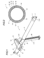
- crossbar 1 for the dashboard which comprises a tube 2 and a set of functional elements 3 support or support mounted on the tube 2, namely for example, two flanges d end 4, a strut 5 and a steering column support 6.
- the end flanges 4 are fitted at each end of the tube 2 and conventionally allow the tube to be fixed to the two vertical uprights of the body (not shown) by screwing through the openings 7.
- the strut 5 conventionally serves to connect the tube 2 to the vehicle floor and the steering column support 6 allows one hand to fix the steering column by screwing by means of the tabs 8 and serves on the other hand to connect the tube 2 to the apron of the vehicle by means of a prolongation 9 U terminated by a support plate 10 in which is formed a screw opening 11.
- tube 2 which is too short to directly connect the two vertical uprights before the bodywork, but which is extended in its longitudinal general direction by one or more extension elements made of plastic, composite or metallic material, conferring on the assembly a sufficient length to connect the two vertical uprights before the bodywork.
- the tube 2 is composed of several concentric layers 12, which follow each other radially and which are each formed of son 13 of glass or carbon embedded or embedded in a polymerized thermoplastic resin 14.
- Each of these layers can be made from independent son, each coated with polymerized thermoplastic resin, or preferably from strips such as constituted by the juxtaposition and / or the stack of several son embedded in the polymerized thermoplastic resin.
- the layers are formed of strips 15 of rectangular section, it is possible to replace them with any other set of son, preferably in layers, which are coated with polymerized thermoplastic resin. It is thus possible to envisage forming layers from strips of square, round, triangular, oval, trapezoidal or other section.
- each winding may comprise one or more or even a multitude of thicknesses of superimposed strips or superimposed son 13 until the desired thickness for the relevant layer of the tube 2 is obtained.
- these thicknesses may be superimposed successively for each of the windings or may more preferably be intercalated alternately, any other combination or arrangement being also possible.
- tube 2 comprises four concentric layers 12, which will be described successively from the center of the tube to its periphery.
- the yarns used for this first layer 16 are glass yarns, which are sufficiently strong mechanically and thermally and which are satisfactory from an economic point of view.
- This initial transverse winding forms a tubular base structure serving as a support for the upper layers and gives the tube 2 good compressive strength to withstand the forces tending to crush and the weight of the functional elements and devices and accessories that he supports.
- the second layer 17 comprises glass threads coated with polymerized thermoplastic resin, which are arranged substantially longitudinally with respect to the general direction of the tube, that is to say at an angle between 0 ° and 10 ° relative to the general direction of the tube 2.
- This longitudinal arrangement of the son of the layer 17 also allows the cross member 1 to withstand the buckling forces which otherwise tend to cause the bending of the tube 2 subjected to a normal compressive force in case of side impact.
- the tube 2 then comprises a third layer 18 which comprises several crossed windings, inclined with respect to the longitudinal general direction of the tube 2, of carbon threads coated with polymerized thermoplastic resin.
- This third layer 18 allows the tube to resist torsion, and thus the vibrations of the steering column which result in a torque tending to twist the crosspiece 1.
- This third layer 18 is preferably located near the periphery of the tube 2 because the torsion resistance obtained increases the further radially away from the son of the longitudinal axis of the tube.
- the tube 2 comprises a fourth layer 19 which constitutes the outer peripheral layer of the tube and which comprises at least one winding having an angle of between 70 ° and 90 ° with respect to the general direction of the tube, of thermoplastic resin-coated glass wires. polymerized.
- This last layer 19 provides an external surface adapted to the fixing of functional elements such as 3 based on plastic material on the tube 2 by welding or gluing, because its winding substantially transverse to the general direction of the tube gives it increased strength. tearing for the functional elements that are attached to it.
- this single winding could be replaced by two windings inclined in opposite directions and crossed with respect to each other.
- each of these different layers 12 can be multiplied in number.
- other layers can be added to the tube of the invention, the claimed layers representing only the essential means of the invention.
- the variant of the tube 2 shown on the Figures 4 and 5 comprises an additional layer 20 interposed in the middle of the second layer 17.
- the tube 2 becomes brittle at the burst. It is then necessary to interpose son wound inclined so as to increase the cohesion of the assembly and thus avoid cracking.
- the additional layer 20 shown on the figure 5 is for example formed of two crossed windings, inclined at an angle of about 85 °.
- each of the layers is not necessarily identical, the importance of each depending on the resulting mechanical, dimensional and weight characteristics desired for the tube 2, as well as economic considerations or related to manufacturing.
- the various son 13 and strips 15 forming part of the tube 2 are each embedded or embedded in a polymerized thermoplastic resin, which may be identical for all the layers 12 of the tube or different from one layer to another provided that it is compatible with the other polymerized thermoplastic resins used so that the different layers of the tube can be unified and consolidated by hot melting then solidification of these polymerized thermoplastic resins over substantially the entire length of the tube.
- a polymerized thermoplastic resin which may be identical for all the layers 12 of the tube or different from one layer to another provided that it is compatible with the other polymerized thermoplastic resins used so that the different layers of the tube can be unified and consolidated by hot melting then solidification of these polymerized thermoplastic resins over substantially the entire length of the tube.
- thermoplastic resins are preferably based on polypropylene or polyamide.
- the crossbar 1 of the dashboard according to the invention may also comprise functional elements 3 support or support which are secured to the tube 2. Not limited to: a strut of force 5, end flanges 4 and a steering column support 2 as shown in FIG. figure 1 .
- One or more extension elements may also be provided to extend the tube 2 in its longitudinal general direction.
- These functional elements 3 are preferably manufactured independently to the tube 2 and are then reported thereon in particular by welding or gluing.
- These functional elements 3 may advantageously be entirely or partially made of plastic, which ensures, in addition to a significant weight gain and a lower cost, an excellent connection with the tube 2.
- the laser welding technique can be used for this purpose.
- the peripheral layer 19 of the tube is made opaque, and preferably of black color, while the zone of attachment to the tube of the functional elements 3 is transparent to the laser light used.
- This zone of attachment to the tube may be made for example in the form of rings 21 completely or partially surrounding the tube 2.
- the laser welding technique consists, after positioning the functional elements 3 on the tube 2, to pass a laser beam through the transparent attachment zone of the functional elements 3, which will warm up and locally melt the opaque or black part tube 2 below, which in turn will heat up and locally melt the transparent attachment area in contact with it.
- These two contact surfaces are intended to be compatible. They mingle with the molten state and solidify themselves strongly by cooling and hardening.
- the functional elements 3 may advantageously be reinforced by glass fibers, glass wires, metal parts or ribs injected plastic such as 22.
- a metal functional element, including extension, is also conceivable.
- the first method is a continuous process that uses the pull-winding technique.
- Dispensers of strips and / or yarns for example in the form of reels 23, supply strips 15 and / or yarns 13 with a longitudinal laying device 24 and a winding device 25 comprising a plurality of covering drums 26 which deposit strips 15 or son 13 around a mandrel 27.
- the wrapping drums 26 perform the different windings of the threads and / or belts by rotation around the mandrel 27.
- the different inclinations of the windings are obtained by varying the speed of rotation of the wrapping drums 26.
- two successive wrapping drums 26 which rotate in opposite directions.
- This heating unit 28 preferably comprises a heating sleeve which makes it possible to calibrate the tube by giving it its external shape.
- a downstream traction unit 29 is also used, for example a two-track pulling belt, which pulls on the consolidated pipe to extract it from the mandrel 27 and bring it to the next unit of the manufacturing process.
- This next unit is a cutting station 30 in which the tube thus formed is cut into sections at the desired length.
- this time is a batch process that allows to form a single tube at a time.
- the wires can not be arranged perfectly longitudinally.
- a minimum angle of about 5 ° must be achieved.
- this winding step is then followed by a heating step not shown in order to melt the various thermoplastic resins and thus to bind together the concentric layers of the tube over the entire length of the latter by hot melting then solidification. This provides a great rigidity to the tube over its entire length.
Landscapes
- Engineering & Computer Science (AREA)
- Chemical & Material Sciences (AREA)
- Combustion & Propulsion (AREA)
- Transportation (AREA)
- Mechanical Engineering (AREA)
- Architecture (AREA)
- Structural Engineering (AREA)
- Laminated Bodies (AREA)
Abstract
Description
La présente invention se rapporte à une traverse tubulaire composite légère, par exemple réalisée par la technique du pull-winding, pour un tableau de bord de véhicule automobile.The present invention relates to a lightweight composite tubular cross member, for example made by the pull-winding technique, for a dashboard of a motor vehicle.
Dans le domaine de la construction des automobiles, on cherche actuellement à alléger au maximum les véhicules pour économiser le carburant. Ceci se traduit par le remplacement de certains éléments métalliques, notamment des pièces de carrosserie ou de structure, par des pièces similaires en matière plastique plus légères. Les métaux légers, tels que l'aluminium sont utilisés, mais réservés aux véhicules haut de gamme en raison de leur coût élevé.In the field of automobile construction, efforts are currently being made to reduce vehicles as much as possible in order to save fuel. This results in the replacement of certain metal elements, including bodywork or structural parts, with similar pieces of lighter plastics. Light metals, such as aluminum, are used but reserved for high-end vehicles because of their high cost.
L'inconvénient des pièces en matière plastique par rapport à celles en métal est leur plus faible résistance mécanique, aussi les constructeurs limitent-ils principalement l'utilisation des pièces en matière plastiques à des structures de parement et d'habillage tout en conservant l'utilisation des pièces métalliques pour des structures de châssis et de renfort.The disadvantage of plastic parts compared to metal parts is their lower mechanical strength, so manufacturers mainly limit the use of plastic parts to cladding and cladding structures while retaining the use of metal parts for frame and reinforcement structures.
Parmi ces structures habituellement en métal, on peut citer la traverse de tableau de bord, qui s'étend transversalement au véhicule à l'avant de l'habitacle et qui est fixée au niveau de ses extrémités aux montants de carrosserie.Among these structures usually made of metal, there may be mentioned the dashboard crossbar, which extends transversely to the vehicle at the front of the passenger compartment and which is fixed at its ends to the body uprights.
Cette traverse remplit deux fonctions importantes : elle sert tout d'abord à rigidifier la caisse du véhicule automobile en reliant les deux flancs du véhicule. Elle joue ainsi un rôle d'étai servant à conserver la largeur du véhicule en cas de choc latéral et empêchant l'enfoncement pour protéger les passagers dans l'habitacle. Elle sert ensuite de support pour plusieurs éléments fonctionnels du véhicule, dont le tableau de bord, également appelé planche de bord, la colonne de direction et son volant, ainsi qu'éventuellement les airbags, la boîte à gants et/ou des conduits d'air du système de climatisation.This crossbar performs two important functions: it serves first to stiffen the body of the motor vehicle by connecting the two sides of the vehicle. It acts as a strut to maintain the width of the vehicle in case of side impact and preventing depression to protect passengers in the cabin. It then serves as a support for several functional elements of the vehicle, including the dashboard, also called the dashboard, the steering column and its steering wheel, as well as possibly the airbags, the glove box and / or ducts. air conditioning system.
Du fait de sa double fonction, cette traverse doit être très rigide et capable de supporter de nombreuses contraintes de nature variée. En effet, elle doit être capable de résister :
- à la flexion pour ne pas plier sous le poids des différents éléments fonctionnels et accessoires qu'elle supporte,
- au flambage pour ne pas se déformer ou se rompre en cas d'accident avec choc latéral,
- à la flexion pour éviter le recul du volant susceptible de gravement blesser le conducteur en cas d'accident avec choc frontal, et
- à la torsion pour résister et ne pas entrer en résonance avec les vibrations du volant et de la colonne de direction qui sont des pièces métalliques lourdes.
- bending so as not to bend under the weight of the various functional elements and accessories that it supports,
- buckling so as not to deform or break in the event of an accident with side impact,
- bending to prevent the steering wheel from recoiling injure the driver in the event of a frontal impact accident, and
- torsion to resist and not resonate with the vibrations of the steering wheel and the steering column which are heavy metal parts.
A cause de ces sollicitations, nombreuses, importantes et variées, qui s'exercent sur cette pièce, il n'est pas évident de la remplacer par une pièce en matière plastique plus légère. Pour lui conférer une rigidité suffisante, un tel remplacement impliquerait en effet d'augmenter considérablement l'épaisseur de la traverse, ce qui se traduirait par une augmentation désavantageuse de sa masse et de son coût, et par un volume global de la pièce beaucoup plus important, incompatible avec l'espace exigu disponible pour la mise en place de la traverse dans un environnement très encombré.Because of these solicitations, numerous, important and varied, which are exerted on this piece, it is not clear to replace it by a piece in lighter plastic material. In order to give it sufficient rigidity, such a replacement would in fact involve considerably increasing the thickness of the cross-member, which would result in a disadvantageous increase in its mass and its cost, and in an overall volume of the part much more important, incompatible with the cramped space available for the installation of the crossbar in a very congested environment.
Même si dans l'art antérieur quelques traverses composites à base de métal et de matières plastiques ont été proposées, toutes ces contraintes expliquent que la réalisation d'une traverse de tableau de bord complètement sans métal n'a pas été possible jusqu'à présent.Although in the prior art some composite sleepers based on metal and plastics have been proposed, all these constraints explain that the realization of a dashboard crossbar completely without metal has not been possible until now .
Le but de l'invention consiste justement à trouver une alternative à ces traverses en métal en proposant une traverse de tableau de bord entièrement non métallique, suffisamment rigide pour supporter les équipements et pour répondre aux exigences de résistance aux chocs et aux vibrations, qui soit légère et économique, tout en étant facile à fabriquer.The object of the invention is precisely to find an alternative to these metal sleepers by proposing a completely non-metallic dashboard crossbar, rigid enough to support the equipment and to meet the requirements of resistance to shock and vibration, which is light and economical, while being easy to manufacture.
On connait également par le modèle d'utilité
L'importante rigidité nécessaire à l'application visée est obtenue par la forme coudée de cet élément tubulaire qui s'étend du pilier avant gauche du véhicule jusqu'au sol du véhicule au niveau du tunnel de cardan.The important rigidity required for the intended application is obtained by the bent shape of this tubular element which extends from the left front pillar of the vehicle to the ground of the vehicle at the gimbal tunnel.
L'invention enseigne un nouveau type de traverse non métallique, qui est suffisamment rigide pour servir de traverse de bord alors qu'elle conserve une direction générale rectiligne.The invention teaches a new type of nonmetallic cross member, which is rigid enough to serve as an edge transom while retaining a rectilinear general direction.
Pour cela, l'invention propose une traverse de tableau de bord pour un véhicule automobile qui comprend un tube de direction générale rectiligne, composé d'une succession de couches concentriques, formées chacune de fils de verre enrobés d'une résine thermoplastique polymérisée ou de fils de carbone enrobés d'une résine thermoplastique polymérisée compatible, ceux-ci étant unifiés sur sensiblement toute la longueur du tube par fusion à chaud puis consolidation des résines thermoplastiques polymérisées.For this, the invention proposes a dashboard cross member for a motor vehicle which comprises a steering tube general rectilinear, consisting of a succession of concentric layers, each formed of glass son coated with a polymerized thermoplastic resin or carbon son coated with a polymerized thermoplastic resin compatible, these being unified over substantially the entire length of the tube by hot melting then consolidation of polymerized thermoplastic resins.
Ce tube comprend successivement, en allant du centre du tube vers sa périphérie, au moins :
- une première couche comprenant au moins un enroulement présentant un angle d'enroulement compris entre 30° et 90° par rapport à la direction générale longitudinale du tube, de fils de verre enrobés de la résine thermoplastique polymérisée ;
- une deuxième couche comprenant des fils de verre disposés sensiblement longitudinalement par rapport à la direction générale du tube, c'est-à-dire présentant un angle d'hélice à faible pas, compris entre 0° et 10° par rapport à la direction générale longitudinale du tube, et enrobés de la résine thermoplastique polymérisée ;
- une troisième couche comprenant au moins deux enroulements croisés, inclinés selon un angle compris entre 40° et 60° par rapport à la direction générale longitudinale du tube, de fils de carbone enrobés de la résine thermoplastique polymérisée compatible ; et
- une quatrième couche comprenant au moins un enroulement présentant un angle compris entre 70° et 90° par rapport à la direction générale du tube, de fils de verre enrobés de la résine thermoplastique polymérisée.
- a first layer comprising at least one winding having a winding angle of between 30 ° and 90 ° with respect to the longitudinal direction of the tube, glass wires coated with the polymerized thermoplastic resin;
- a second layer comprising glass threads arranged substantially longitudinally with respect to the general direction of the tube, that is to say having a low pitch helix angle of between 0 ° and 10 ° with respect to the general direction longitudinal of the tube, and coated with the polymerized thermoplastic resin;
- a third layer comprising at least two crossed windings, inclined at an angle between 40 ° and 60 ° relative to the longitudinal direction of the tube, of carbon son coated with the polymerized thermoplastic resin compatible; and
- a fourth layer comprising at least one winding having an angle between 70 ° and 90 ° relative to the general direction of the tube, glass son coated with the polymerized thermoplastic resin.
Selon un mode de réalisation préférentiel, ces couches peuvent être réalisées à partir de bandes constituées chacune d'une juxtaposition de fils de verre ou de fils de carbone enrobés d'une résine thermoplastique polymérisée, telle que du polypropylène ou du polyamide, l'ensemble des fils étant unifié sur sensiblement toute la longueur du tube par fusion à chaud puis solidification des résines thermoplastiques polymérisées.According to a preferred embodiment, these layers can be made from strips each consisting of a juxtaposition of glass son or carbon son coated with a polymerized thermoplastic resin, such as polypropylene or polyamide, the whole son being unified over substantially the entire length of the tube by hot melting and solidification of the polymerized thermoplastic resins.
Par l'utilisation combinée de fibres de verre et de fibres de carbone, disposées les unes par rapport autres de manière adaptée et noyées dans une matrice en matière thermoplastique, la traverse pour tableau de bord selon l'invention présente une rigidité multidirectionnelle suffisante pour respecter les exigences des constructeurs en terme de sécurité, avec un gain de poids pouvant aller jusqu'à trente à quarante pourcents et une augmentation de diamètre limitée restant acceptable.By the combined use of glass fibers and carbon fibers, arranged relative to each other in a suitable manner and embedded in a thermoplastic matrix, the dashboard cross member according to the invention has a multidirectional rigidity. sufficient to meet the requirements of manufacturers in terms of safety, with a weight gain of up to thirty to forty percent and a limited diameter increase remaining acceptable.
L'utilisation de matière plastique se traduit également par l'utilisation d'outils de moulage, de soudage et de fabrication qui sont en général moins chers que ceux habituellement utilisés pour les pièces en métal.The use of plastic material also results in the use of molding, welding and fabrication tools which are generally less expensive than those usually used for metal parts.
La traverse de tableau de bord peut comporter en outre des éléments fonctionnels d'appui ou de support entièrement ou partiellement en matière plastique, notamment une jambe de force, des flasques d'extrémité et/ou un support de colonne de direction, qui peuvent facilement être solidarisés par soudage, soudage laser ou collage ou autre moyen d'immobilisation sur la traverse de tableau de bord à base de matière thermoplastique. La traverse de tableau de bord selon l'invention peut également être prolongée dans sa direction générale longitudinale par un ou plusieurs éléments de prolongation métalliques ou réalisés entièrement ou partiellement en matière plastique.The dashboard crossmember may further comprise functional support or support elements wholly or partially made of plastic material, in particular a strut, end flanges and / or a steering column support, which can easily be be secured by welding, laser welding or gluing or other means of immobilization on the dashboard dashboard based on thermoplastic material. The dashboard cross member according to the invention may also be extended in its longitudinal general direction by one or more metal extension elements or made wholly or partially of plastics material.
La traverse de tableau de bord selon l'invention peut par exemple être fabriquée par un procédé continu du type pull-winding, ou par un procédé discontinu d'enroulement filamentaire autour d'un mandrin fixe ou rotatif.The dashboard cross member according to the invention may for example be manufactured by a continuous process of the pull-winding type, or by a discontinuous method of filament winding around a fixed or rotating mandrel.
D'autres caractéristiques et avantages de l'invention apparaîtront dans la description qui suit, donnée à titre d'exemple et accompagnée des dessins dans lesquels :
- la
figure 1 est une vue en perspective d'ensemble d'un exemple de traverse pour tableau de bord selon l'invention ; - la
figure 2 est une vue en coupe schématique d'un premier exemple de tube de traverse pour tableau de bord selon l'invention ; - la
figure 3 est une vue en perspective partiellement éclatée, du tube de lafigure 3 illustrant sa constitution ; - la
figure 4 est une vue en coupe schématique d'un deuxième exemple de tube de traverse pour tableau de bord selon l'invention ; - la
figure 5 est une vue en perspective partiellement éclatée, du tube de lafigure 4 illustrant sa constitution ; - la
figure 6 est une vue de profil illustrant de manière schématique un procédé de fabrication par pull-winding du tube de traverse pour tableau de bord selon l'invention ; - la
figure 7 est une vue de profil illustrant de manière schématique un autre procédé de fabrication du tube de traverse pour tableau de bord selon l'invention.
- the
figure 1 is an overall perspective view of an example of a dashboard cross member according to the invention; - the
figure 2 is a schematic sectional view of a first example of a dashboard cross tube according to the invention; - the
figure 3 is a partially exploded perspective view of the tube of thefigure 3 illustrating its constitution; - the
figure 4 is a schematic sectional view of a second example of dashboard cross tube according to the invention; - the
figure 5 is a partially exploded perspective view of the tube of thefigure 4 illustrating its constitution; - the
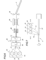
figure 6 is a side view schematically illustrating a method of manufacturing by pull-winding dashboard cross tube according to the invention; - the
figure 7 is a side view schematically illustrating another method of manufacturing the dashboard cross tube according to the invention.
Le système selon la présente invention va maintenant être décrit de façon détaillée en référence aux
Sur la
Les flasques d'extrémité 4 sont emmanchés à chacune des extrémités du tube 2 et permettent classiquement de fixer le tube aux deux montants verticaux de carrosserie (non représentés) par vissage à travers les ouvertures 7.The end flanges 4 are fitted at each end of the
La jambe de force 5 sert classiquement à relier le tube 2 au plancher du véhicule et le support de colonne de direction 6 permet d'une part de fixer la colonne de direction par vissage au moyen des pattes 8 et sert d'autre part à relier le tube 2 au tablier du véhicule au moyen d'une prolongation 9 en U terminée par une platine d'appui 10 dans laquelle est ménagée une ouverture de vissage 11.The strut 5 conventionally serves to connect the
Bien entendu, l'homme du métier pourra imaginer bien d'autres variantes pour ces éléments fonctionnels 3, que ce soit au niveau de leur forme, de leur nature, de leur nombre et/ou de leur taille, selon les besoins particuliers de l'application et le modèle du véhicule à équiper.Of course, those skilled in the art will be able to imagine many other variants for these functional elements 3, whether in terms of their shape, their nature, their number and / or their size, according to the particular needs of the user. application and the model of the vehicle to be equipped.
On pourra par exemple imaginer un tube 2 trop court pour relier directement les deux montants verticaux avant de la carrosserie, mais prolongé selon sa direction générale longitudinale par un ou plusieurs éléments de prolongation en matière plastique, composites ou métalliques, conférant à l'ensemble une longueur suffisante pour relier les deux montants verticaux avant de la carrosserie.For example, it would be possible to imagine a
D'autre part, le tube 2 a été représenté sur les différentes figures comme étant parfaitement rectiligne. On pourra également envisager des variantes dans lesquelles il pourra être légèrement différent, en fonction de l'encombrement, des autres éléments techniques du véhicule situés à proximité et/ou de l'exiguïté de son environnement immédiat, tout en restant globalement rectiligne, c'est-à-dire en conservant une direction générale sensiblement rectiligne.On the other hand, the
Comme le montrent les
La juxtaposition de ces couches 12 concentriques forme l'épaisseur du tube 2 dont les fils 13 de verre ou de carbone assurent la résistance structurelle et dont la résine thermoplastique 14 assure la cohésion d'ensemble par consolidation sur toute la longueur du tube, à savoir par fusion à chaud puis solidification de la résine thermoplastique polymérisée sur toute la longueur du tube.The juxtaposition of these concentric layers 12 forms the thickness of the
Chacune de ces couches peut être réalisée à partir de fils indépendants, enrobés chacun de résine thermoplastique polymérisée, ou préférentiellement à partir de bandes telles que 15 constituées de la juxtaposition et/ou de l'empilement de plusieurs fils noyés dans la résine thermoplastique polymérisée.Each of these layers can be made from independent son, each coated with polymerized thermoplastic resin, or preferably from strips such as constituted by the juxtaposition and / or the stack of several son embedded in the polymerized thermoplastic resin.
Bien que sur les
En outre, chaque enroulement peut comporter une ou plusieurs, voire une multitude d'épaisseurs de bandes 15 ou de fils 13 enrobés superposés, jusqu'à obtenir l'épaisseur souhaitée pour la couche concernée du tube 2.In addition, each winding may comprise one or more or even a multitude of thicknesses of superimposed strips or
Dans le cas où une couche est formée de plusieurs enroulements différents et où plusieurs épaisseurs de chacun d'entre eux sont nécessaires, ces épaisseurs peuvent se superposer successivement pour chacun des enroulements ou peuvent plus préférentiellement s'intercaler alternativement, toute autre combinaison ou disposition étant également possible.In the case where a layer is formed of several different windings and where several thicknesses of each of them are necessary, these thicknesses may be superimposed successively for each of the windings or may more preferably be intercalated alternately, any other combination or arrangement being also possible.
Dans l'exemple représenté sur les
La première couche 16 est formée d'un enroulement de fils 13 ou de bandes 15 de fils 13 enrobés d'une résine thermoplastique polymérisée 14, qui présente un angle compris entre 30° et 90° par rapport à la direction générale du tube 2.The first layer 16 is formed of a winding of
Dans l'exemple représenté sur la
Des propriétés mécaniques similaires pourraient être obtenues en remplaçant, par exemple, cet enroulement transversal unique par deux enroulements inclinés en sens opposé l'un de l'autre, par exemple à environ 30° ou à environ 85° comme par exemple sur la variante de la
Les fils utilisés pour cette première couche 16 sont des fils de verre, qui sont suffisamment résistants sur le plan mécanique et thermique et qui sont satisfaisants d'un point de vue économique.The yarns used for this first layer 16 are glass yarns, which are sufficiently strong mechanically and thermally and which are satisfactory from an economic point of view.
Cet enroulement transversal initial forme une structure tubulaire de base servant de support aux couches supérieures et confère au tube 2 une bonne résistance à la compression lui permettant de résister aux forces ayant tendance à l'écraser et au poids des éléments fonctionnels et dispositifs et accessoires qu'il supporte.This initial transverse winding forms a tubular base structure serving as a support for the upper layers and gives the
La deuxième couche 17 comprend des fils de verre enrobés de résine thermoplastique polymérisée, qui sont disposés sensiblement longitudinalement par rapport à la direction générale du tube, c'est-à-dire selon un angle compris entre 0° et 10° par rapport à la direction générale du tube 2.The second layer 17 comprises glass threads coated with polymerized thermoplastic resin, which are arranged substantially longitudinally with respect to the general direction of the tube, that is to say at an angle between 0 ° and 10 ° relative to the general direction of the
Par cette disposition longitudinale des fils, cette couche 17 permet avantageusement à la traverse 1 de résister aux efforts de flexion qui s'appliquent sur le tube notamment en cas de choc avant, ce qui permet en outre de limiter le recul dangereux de la colonne de direction et du volant dans une telle situation.By this longitudinal arrangement of the yarns, this layer 17 advantageously allows the
Cette disposition longitudinale des fils de la couche 17 permet également à la traverse 1 de résister aux efforts de flambage qui sinon auraient tendance à provoquer le fléchissement du tube 2 soumis à un effort normal de compression en cas de choc latéral.This longitudinal arrangement of the son of the layer 17 also allows the
Le tube 2 comporte ensuite une troisième couche 18 qui comprend plusieurs enroulements croisés, inclinés par rapport à la direction générale longitudinale du tube 2, de fils de carbone enrobés de résine thermoplastique polymérisée.The
Sur l'exemple représenté, la troisième couche 18 est formée de deux enroulements croisés, inclinés diagonalement, c'est-à-dire selon un angle compris entre 40° et 60° et préférentiellement voisin de 45° par rapport à la direction générale longitudinale du tube 2.In the example shown, the third layer 18 is formed of two crossed windings, diagonally inclined, that is to say at an angle of between 40 ° and 60 ° and preferably close to 45 ° with respect to the longitudinal general direction. of the
Cette troisième couche 18 permet au tube de résister à la torsion, et ainsi aux vibrations de la colonne de direction qui se traduisent par un couple tendant à vriller la traverse 1.This third layer 18 allows the tube to resist torsion, and thus the vibrations of the steering column which result in a torque tending to twist the
On peut ainsi superposer alternativement plusieurs épaisseurs de ces enroulements croisés jusqu'à obtenir la résistance mécanique nécessaire recherchée.It is thus possible to superimpose alternately several thicknesses of these crossed windings until obtaining the required mechanical strength.
Cette troisième couche 18 est préférentiellement située à proximité de la périphérie du tube 2 car la résistance à la torsion obtenue augmente plus on éloigne radialement les fils de l'axe longitudinal du tube.This third layer 18 is preferably located near the periphery of the
Malgré leur coût supérieur, les fils de carbone beaucoup plus résistants sont ici préférés aux fils de verre, car les efforts de torsion subis par le tube sont très importants et constituent le problème majeur à résoudre.Despite their higher cost, the much stronger carbon son are here preferred to the glass son, because the torsion forces experienced by the tube are very important and are the major problem to solve.
Le tube 2 comporte une quatrième couche 19 qui constitue la couche périphérique externe du tube et qui comprend au moins un enroulement présentant un angle compris entre 70° et 90° par rapport à la direction générale du tube, de fils de verre enrobés de résine thermoplastique polymérisée.The
Cette dernière couche 19 offre une surface extérieure adaptée à la fixation d'éléments fonctionnels tels que 3 à base de matière plastique sur le tube 2 par soudage ou par collage, car son enroulement sensiblement transversal à la direction générale du tube lui confère une résistance accrue à l'arrachement pour les éléments fonctionnels qui lui sont solidarisés.This last layer 19 provides an external surface adapted to the fixing of functional elements such as 3 based on plastic material on the
Là encore, cet enroulement unique pourrait être remplacé par deux enroulements inclinés en sens opposé et croisés l'un par rapport à l'autre.Again, this single winding could be replaced by two windings inclined in opposite directions and crossed with respect to each other.
Bien entendu, chacune de ces différentes couches 12 peut être multipliée en nombre. De même, d'autres couches peuvent être ajoutées au tube de l'invention, les couches revendiquées ne représentant que les moyens essentiels de l'invention.Of course, each of these different layers 12 can be multiplied in number. Similarly, other layers can be added to the tube of the invention, the claimed layers representing only the essential means of the invention.
Ainsi par exemple, la variante du tube 2 représentée sur les
En effet, lorsque l'épaisseur de la couche 17 qui renferme les fils sensiblement longitudinaux est importante, le tube 2 devient fragile à l'éclatement. Il est alors nécessaire d'intercaler des fils enroulés de manière inclinée afin d'augmenter la cohésion de l'ensemble et ainsi d'éviter la fissuration.Indeed, when the thickness of the layer 17 which encloses the substantially longitudinal son is important, the
On peut par exemple déposer alternativement, toutes les quatre à cinq épaisseurs de fils 13 ou de bandes 15 de fils sensiblement longitudinaux, une épaisseur de fils 13 ou de bandes 15 de fils inclinés selon un angle compris entre 10° et 85°.For example, it is possible, for example, to deposit, alternately, all four to five thicknesses of
La couche supplémentaire 20 représentée sur la
Evidemment, plusieurs couches supplémentaires 20 similaires peuvent être nécessaires selon l'épaisseur de la couche 17.Of course, several similar additional layers may be required depending on the thickness of the layer 17.
De la même façon, l'épaisseur de chacune des couches n'est pas forcément identique, l'importance de chacune dépendant des caractéristiques résultantes mécaniques, dimensionnelles et pondérales souhaitées pour le tube 2, ainsi que de considérations économiques ou liées à la fabrication.In the same way, the thickness of each of the layers is not necessarily identical, the importance of each depending on the resulting mechanical, dimensional and weight characteristics desired for the
Les différents fils 13 et bandes 15 faisant partie du tube 2 sont enrobés ou noyés chacun dans une résine thermoplastique polymérisée, qui peut être identique pour toutes les couches 12 du tube ou différente d'une couche à l'autre à condition d'être compatible avec les autres résines thermoplastiques polymérisées utilisées de manière que les différentes couches du tube puissent être unifiées et consolidées par fusion à chaud puis solidification de ces résines thermoplastiques polymérisées, sur sensiblement toute la longueur du tube.The
Ces résines thermoplastiques polymérisées compatibles sont préférentiellement à base de polypropylène ou de polyamide.These compatible polymerized thermoplastic resins are preferably based on polypropylene or polyamide.
Il s'agit de préférence de résines qui ont une base chimique commune, et plus préférentiellement d'une seule et même résine pour l'ensemble des couches 12 du tube et encore plus préférentiellement de polypropylène.These are preferably resins which have a common chemical base, and more preferably of one and the same resin for all the layers 12 of the tube and even more preferably of polypropylene.
Outre le tube 2 décrit précédemment, la traverse 1 de tableau de bord selon l'invention peut comporter également des éléments fonctionnels 3 d'appui ou de support qui sont solidarisés au tube 2. On peut citer de manière non limitative : une jambe de force 5, des flasques d'extrémité 4 et un support de colonne de direction 2 comme représenté sur la
Ces éléments fonctionnels 3 sont préférentiellement fabriqués indépendamment au tube 2 et sont ensuite rapportés sur celui-ci notamment par soudage ou par collage.These functional elements 3 are preferably manufactured independently to the
Ces éléments fonctionnels 3 peuvent avantageusement être entièrement ou partiellement réalisés en matière plastique, ce qui assure, outre un gain de poids non négligeable et un coût plus réduit, une excellente solidarisation avec le tube 2.These functional elements 3 may advantageously be entirely or partially made of plastic, which ensures, in addition to a significant weight gain and a lower cost, an excellent connection with the
Avantageusement, on peut utiliser pour cela la technique de soudage par laser. Dans ce cas, la couche périphérique 19 du tube est réalisée opaque, et préférentiellement de couleur noire, alors que la zone de rattachement au tube des éléments fonctionnels 3 est transparente à la lumière laser utilisée. Cette zone de rattachement au tube peut être réalisée par exemple sous la forme de bagues 21 entourant entièrement ou partiellement le tube 2.Advantageously, the laser welding technique can be used for this purpose. In this case, the peripheral layer 19 of the tube is made opaque, and preferably of black color, while the zone of attachment to the tube of the functional elements 3 is transparent to the laser light used. This zone of attachment to the tube may be made for example in the form of
La technique de soudage par laser consiste, après avoir positionné les éléments fonctionnels 3 sur le tube 2, à faire passer un faisceau laser à travers la zone de rattachement transparente des éléments fonctionnels 3, qui va échauffer et faire fondre localement la partie opaque ou noire du tube 2 située en dessous, qui à son tour va échauffer et faire fondre localement la zone de rattachement transparente en contact avec elle. Ces deux surfaces de contact sont prévues pour être compatibles. Elles se mêlent à l'état fondu et se solidarisent fortement en refroidissant et en durcissant.The laser welding technique consists, after positioning the functional elements 3 on the
Afin d'offrir une résistance mécanique adaptée à leur usage, les éléments fonctionnels 3 peuvent avantageusement être renforcés par des fibres de verre, des fils de verre, des pièces métalliques ou des nervures en plastique injecté telles que 22. Un élément fonctionnel métallique, notamment de prolongation, est également envisageable.In order to provide a mechanical resistance adapted to their use, the functional elements 3 may advantageously be reinforced by glass fibers, glass wires, metal parts or ribs injected plastic such as 22. A metal functional element, including extension, is also conceivable.
Après avoir décrit la constitution originale de la traverse de tableau de bord 1 selon l'invention, nous allons maintenant décrire à titre d'exemple non limitatif deux procédés de fabrication, utilisables pour obtenir un tube 2 conforme à l'invention.After describing the original constitution of the
Le premier procédé, représenté schématiquement sur la
Des distributeurs de bandes et/ou de fils, par exemple sous la forme de bobines 23 alimentent en bandes 15 et/ou en fils 13 un dispositif de dépose longitudinale 24 ainsi qu'un dispositif d'enroulement 25 comportant plusieurs tambours de guipage 26 qui déposent les bandes 15 ou fils 13 autour d'un mandrin 27.Dispensers of strips and / or yarns, for example in the form of
Les tambours de guipage 26 réalisent les différents enroulements des fils et/ou bandes par rotation autour du mandrin 27. On obtient les différentes inclinaisons des enroulements en faisant varier la vitesse de rotation des tambours de guipage 26. Pour réaliser les enroulements croisés, on utilise deux tambours de guipage 26 successifs qui tournent en sens inverse.The wrapping drums 26 perform the different windings of the threads and / or belts by rotation around the
Ces dispositifs sont suivis d'une unité de chauffage 28 qui fait fondre les différentes résines thermoplastiques composant les couches concentriques du tube et réalise ainsi leur cohésion par fusion à chaud puis solidification. Le tube 2 est ainsi consolidé et rigidifié sur toute la longueur du tube. Cette unité de chauffage 28 comprend préférentiellement un manchon chauffant qui permet de calibrer le tube en lui donnant sa forme extérieure.These devices are followed by a
Comme il s'agit d'un procédé de fabrication en continu, on utilise également une unité de traction 29 située en aval, par exemple une bande de tirage à deux chenilles, qui tire sur le tube consolidé pour l'extraire du mandrin 27 et l'amener vers l'unité suivante du procédé de fabrication.Since this is a continuous manufacturing process, a
Cette unité suivante est un poste de découpe 30 dans lequel le tube ainsi constitué se trouve coupé en tronçons à la longueur désirée.This next unit is a cutting
Le deuxième procédé, représenté schématiquement sur la
On utilise cette fois un mandrin 27 rotatif autour duquel on enroule les fils 13 ou les bandes 15. Les bobines 23 de fils 13 ou de bandes 15 sont chargées sur un robot 31 qui se déplace en translation devant le mandrin 27 tout en dévidant les bobines.This time a rotating
Avec un tel procédé, on ne peut pas disposer les fils parfaitement longitudinalement. Un angle minimal d'environ 5° doit être réalisé.With such a process, the wires can not be arranged perfectly longitudinally. A minimum angle of about 5 ° must be achieved.
Là encore, cette étape d'enroulement est ensuite suivie par une étape de chauffage non représentée afin de faire fondre les différentes résines thermoplastiques et ainsi de lier entre elles les couches concentriques du tube sur toute la longueur de celui-ci par fusion à chaud puis solidification. Ceci procure une grande rigidité au tube sur toute sa longueur.Again, this winding step is then followed by a heating step not shown in order to melt the various thermoplastic resins and thus to bind together the concentric layers of the tube over the entire length of the latter by hot melting then solidification. This provides a great rigidity to the tube over its entire length.
De manière évidente, l'invention ne se limite pas aux modes de réalisation préférentiels décrits précédemment et représentés sur les différentes figures. Bien d'autres variantes sont possibles tout en restant dans le principe inventif défini par les revendications.Obviously, the invention is not limited to the preferred embodiments previously described and shown in the various figures. Many other variants are possible while remaining in the inventive principle defined by the claims.
Claims (15)
Applications Claiming Priority (1)
| Application Number | Priority Date | Filing Date | Title |
|---|---|---|---|
| FR1160719A FR2983161B1 (en) | 2011-11-24 | 2011-11-24 | LIGHTWEIGHT COMPOSITE TUBULAR TRAVERSE FOR AUTOMOTIVE VEHICLE DASHBOARD. |
Publications (2)
| Publication Number | Publication Date |
|---|---|
| EP2597017A1 true EP2597017A1 (en) | 2013-05-29 |
| EP2597017B1 EP2597017B1 (en) | 2016-04-20 |
Family
ID=47177846
Family Applications (1)
| Application Number | Title | Priority Date | Filing Date |
|---|---|---|---|
| EP12193383.2A Not-in-force EP2597017B1 (en) | 2011-11-24 | 2012-11-20 | Lightweight composite tubular crossmember for an automobile dashboard |
Country Status (2)
| Country | Link |
|---|---|
| EP (1) | EP2597017B1 (en) |
| FR (1) | FR2983161B1 (en) |
Cited By (9)
| Publication number | Priority date | Publication date | Assignee | Title |
|---|---|---|---|---|
| FR3006393A1 (en) * | 2013-05-30 | 2014-12-05 | Peugeot Citroen Automobiles Sa | METHOD FOR ASSEMBLING TUBES BY ADDING GLASS AND DASHBOARD TRAVERSE OBTAINED BY SUCH A METHOD |
| FR3014816A1 (en) * | 2013-12-18 | 2015-06-19 | Peugeot Citroen Automobiles Sa | ASSEMBLY COMPRISING A DASHBOARD TRAILER AND A FIXING BRACKET FOR AN AIRBAG |
| FR3014818A1 (en) * | 2013-12-18 | 2015-06-19 | Peugeot Citroen Automobiles Sa | ASSEMBLY COMPRISING A DASHBOARD TRAILER FOR A MOTOR VEHICLE AND TWO SIDE MOUNTS FOR ATTACHING IT TO THE VEHICLE BODY |
| EP3173317A3 (en) * | 2015-11-06 | 2017-08-30 | Audi Ag | Node structure with improved crash properties due to arrestor cable and/or support band, method for preparation and vehicle frame |
| WO2017220562A1 (en) | 2016-06-20 | 2017-12-28 | Institut De Recherche Technologique Jules Verne | Method for producing a composite material part, steering column support member and lower space cross member produced by such a method |
| DE102016217670A1 (en) | 2016-09-15 | 2018-03-15 | Bayerische Motoren Werke Aktiengesellschaft | Instrument panel support |
| CN108263497A (en) * | 2016-12-31 | 2018-07-10 | 郑州吉田专利运营有限公司 | Carbon fabric composite material vehicle skeleton and preparation method thereof |
| CN108263494A (en) * | 2016-12-31 | 2018-07-10 | 郑州吉田专利运营有限公司 | The carbon fiber winding structural member of winding and its space framework and the application of preparation |
| EP3820763A4 (en) * | 2018-07-12 | 2022-04-13 | Shanghai Yanfeng Jin Qiao Automotive Trim Systems Co., Ltd. | Cross-member structure for vehicle |
Families Citing this family (1)
| Publication number | Priority date | Publication date | Assignee | Title |
|---|---|---|---|---|
| CN113858657A (en) * | 2021-09-26 | 2021-12-31 | 浙江吉利控股集团有限公司 | Instrument panel beam tube, manufacturing method thereof and automobile |
Citations (6)
| Publication number | Priority date | Publication date | Assignee | Title |
|---|---|---|---|---|
| GB1214205A (en) * | 1967-05-01 | 1970-12-02 | United Aircraft Corp | Composite reinforced plastics pipe |
| FR2401595A5 (en) * | 1971-05-21 | 1979-03-23 | Creators Ltd | Reinforced plastic pipe-with woven tubular netting embedded - in its seamless extruded wall |
| WO1992001885A1 (en) * | 1990-07-19 | 1992-02-06 | Wavin B.V. | Composite pipe with one or more layers of strip material wound around an inner pipe and reel provided with such a composite pipe wound onto it |
| EP1415897A2 (en) * | 2002-11-01 | 2004-05-06 | Calsonic Kansei Corporation | Cross member and manufacturing method thereof |
| DE20221554U1 (en) | 2002-09-02 | 2006-05-24 | Lisa Dräxlmaier GmbH | Cross-member for vehicle incorporates curved tubes or curved bars in area between A-pillar and propeller shaft tunnel, tubes being made from fiber-reinforced plastic and bars having metal-plastic hybrid structure |
| DE102009006960A1 (en) * | 2009-01-31 | 2010-08-05 | Aksys Gmbh | Plastic-metal hybrid vehicle-dashboard-assembly support for motor vehicle, has cross member determined for absorbing side impact forces, where support is made from support structure and cross member by pressing and/or injection molding |
-
2011
- 2011-11-24 FR FR1160719A patent/FR2983161B1/en not_active Expired - Fee Related
-
2012
- 2012-11-20 EP EP12193383.2A patent/EP2597017B1/en not_active Not-in-force
Patent Citations (6)
| Publication number | Priority date | Publication date | Assignee | Title |
|---|---|---|---|---|
| GB1214205A (en) * | 1967-05-01 | 1970-12-02 | United Aircraft Corp | Composite reinforced plastics pipe |
| FR2401595A5 (en) * | 1971-05-21 | 1979-03-23 | Creators Ltd | Reinforced plastic pipe-with woven tubular netting embedded - in its seamless extruded wall |
| WO1992001885A1 (en) * | 1990-07-19 | 1992-02-06 | Wavin B.V. | Composite pipe with one or more layers of strip material wound around an inner pipe and reel provided with such a composite pipe wound onto it |
| DE20221554U1 (en) | 2002-09-02 | 2006-05-24 | Lisa Dräxlmaier GmbH | Cross-member for vehicle incorporates curved tubes or curved bars in area between A-pillar and propeller shaft tunnel, tubes being made from fiber-reinforced plastic and bars having metal-plastic hybrid structure |
| EP1415897A2 (en) * | 2002-11-01 | 2004-05-06 | Calsonic Kansei Corporation | Cross member and manufacturing method thereof |
| DE102009006960A1 (en) * | 2009-01-31 | 2010-08-05 | Aksys Gmbh | Plastic-metal hybrid vehicle-dashboard-assembly support for motor vehicle, has cross member determined for absorbing side impact forces, where support is made from support structure and cross member by pressing and/or injection molding |
Cited By (12)
| Publication number | Priority date | Publication date | Assignee | Title |
|---|---|---|---|---|
| FR3006393A1 (en) * | 2013-05-30 | 2014-12-05 | Peugeot Citroen Automobiles Sa | METHOD FOR ASSEMBLING TUBES BY ADDING GLASS AND DASHBOARD TRAVERSE OBTAINED BY SUCH A METHOD |
| FR3014816A1 (en) * | 2013-12-18 | 2015-06-19 | Peugeot Citroen Automobiles Sa | ASSEMBLY COMPRISING A DASHBOARD TRAILER AND A FIXING BRACKET FOR AN AIRBAG |
| FR3014818A1 (en) * | 2013-12-18 | 2015-06-19 | Peugeot Citroen Automobiles Sa | ASSEMBLY COMPRISING A DASHBOARD TRAILER FOR A MOTOR VEHICLE AND TWO SIDE MOUNTS FOR ATTACHING IT TO THE VEHICLE BODY |
| WO2015090988A1 (en) * | 2013-12-18 | 2015-06-25 | Peugeot Citroen Automobiles Sa | Assembly comprising a dashboard cross-member and a support for securing an airbag |
| WO2015090989A1 (en) * | 2013-12-18 | 2015-06-25 | Peugeot Citroen Automobiles Sa | Assembly comprising a dashboard cross-member for a motor vehicle and two side supports for securing the cross-member to the body of the vehicle |
| EP3173317A3 (en) * | 2015-11-06 | 2017-08-30 | Audi Ag | Node structure with improved crash properties due to arrestor cable and/or support band, method for preparation and vehicle frame |
| WO2017220562A1 (en) | 2016-06-20 | 2017-12-28 | Institut De Recherche Technologique Jules Verne | Method for producing a composite material part, steering column support member and lower space cross member produced by such a method |
| DE102016217670A1 (en) | 2016-09-15 | 2018-03-15 | Bayerische Motoren Werke Aktiengesellschaft | Instrument panel support |
| CN108263497A (en) * | 2016-12-31 | 2018-07-10 | 郑州吉田专利运营有限公司 | Carbon fabric composite material vehicle skeleton and preparation method thereof |
| CN108263494A (en) * | 2016-12-31 | 2018-07-10 | 郑州吉田专利运营有限公司 | The carbon fiber winding structural member of winding and its space framework and the application of preparation |
| EP3820763A4 (en) * | 2018-07-12 | 2022-04-13 | Shanghai Yanfeng Jin Qiao Automotive Trim Systems Co., Ltd. | Cross-member structure for vehicle |
| US11352067B2 (en) | 2018-07-12 | 2022-06-07 | Shanghai Yanfeng Jinqiao Automotive Trim Systems Co. Ltd. | Cross-member structure for vehicle |
Also Published As
| Publication number | Publication date |
|---|---|
| FR2983161A1 (en) | 2013-05-31 |
| FR2983161B1 (en) | 2013-11-08 |
| EP2597017B1 (en) | 2016-04-20 |
Similar Documents
| Publication | Publication Date | Title |
|---|---|---|
| EP2597017B1 (en) | Lightweight composite tubular crossmember for an automobile dashboard | |
| EP2504176B1 (en) | Composite wheel, in particular for a cycle, and method for manufacturing such a wheel | |
| EP3162671B1 (en) | Vehicle crossmember | |
| EP2525965B1 (en) | Method for making an arm for a hinged structure such as a rocker arm for an aircraft landing-gear structure | |
| FR2546473A1 (en) | TUBULAR MATERIAL BASED ON A RESIN REINFORCED BY A TEXTILE MATERIAL AND BICYCLE FRAME OR SIMILAR VEHICLE MADE FROM SUCH A MATERIAL | |
| EP3174791A1 (en) | Tube having a hybrid-type structure, in particular for an aircraft seat | |
| EP3134246A1 (en) | Method for producing a lightweight gear by double overmoulding | |
| WO2016001510A1 (en) | Improved reinforcing transverse cross-member with programmed rupture | |
| FR2936469A1 (en) | Front structure for motor vehicle, has front energy absorption part deformable by crushing that is controlled under form of successive ripples along longitudinal axis of front energy absorption part and rear effort transmission part | |
| EP3083376B1 (en) | Dashboard cross-member comprising bonded compact side supports | |
| EP3245107B1 (en) | Energy-absorbing element for car bumper | |
| EP2032419B1 (en) | Structure part obtained via butt-joining for motor vehicle | |
| EP3331725B1 (en) | Deformable vehicle seat | |
| EP2459404B1 (en) | Jointed glass panel comprising comb-shaped insert, and method for manufacturing said glass panel | |
| EP3826861B1 (en) | Wheel disc and manufacturing tool thereof | |
| EP3670221B1 (en) | Sub-assembly of a motor vehicle comprising a tailgate lining and an interfacing element for a locking zone of the tailgate | |
| WO2016001509A1 (en) | Improved reinforcing transverse cross-member for lateral and frontal impacts | |
| WO2005056928A2 (en) | Rising security barrier | |
| EP1258420B1 (en) | Mudguard from plastic material | |
| WO2015090987A1 (en) | Dashboard cross-member with a side support having a mixed metal-plastic structure | |
| FR3006393A1 (en) | METHOD FOR ASSEMBLING TUBES BY ADDING GLASS AND DASHBOARD TRAVERSE OBTAINED BY SUCH A METHOD | |
| EP3164318B1 (en) | Improved transverse reinforcing brace | |
| FR3020312A1 (en) | ROLLING ASSEMBLY | |
| EP3245108B1 (en) | Energy absorber element for vehicle bumper | |
| FR2801947A1 (en) | HOLLOW BEAM FOR ABSORPTION OF SHOCK ENERGY |
Legal Events
| Date | Code | Title | Description |
|---|---|---|---|
| PUAI | Public reference made under article 153(3) epc to a published international application that has entered the european phase |
Free format text: ORIGINAL CODE: 0009012 |
|
| AK | Designated contracting states |
Kind code of ref document: A1 Designated state(s): AL AT BE BG CH CY CZ DE DK EE ES FI FR GB GR HR HU IE IS IT LI LT LU LV MC MK MT NL NO PL PT RO RS SE SI SK SM TR |
|
| AX | Request for extension of the european patent |
Extension state: BA ME |
|
| 17P | Request for examination filed |
Effective date: 20130923 |
|
| RBV | Designated contracting states (corrected) |
Designated state(s): AL AT BE BG CH CY CZ DE DK EE ES FI FR GB GR HR HU IE IS IT LI LT LU LV MC MK MT NL NO PL PT RO RS SE SI SK SM TR |
|
| RIC1 | Information provided on ipc code assigned before grant |
Ipc: B62D 25/14 20060101AFI20151007BHEP Ipc: B62D 29/04 20060101ALI20151007BHEP |
|
| GRAP | Despatch of communication of intention to grant a patent |
Free format text: ORIGINAL CODE: EPIDOSNIGR1 |
|
| INTG | Intention to grant announced |
Effective date: 20151125 |
|
| GRAS | Grant fee paid |
Free format text: ORIGINAL CODE: EPIDOSNIGR3 |
|
| GRAA | (expected) grant |
Free format text: ORIGINAL CODE: 0009210 |
|
| AK | Designated contracting states |
Kind code of ref document: B1 Designated state(s): AL AT BE BG CH CY CZ DE DK EE ES FI FR GB GR HR HU IE IS IT LI LT LU LV MC MK MT NL NO PL PT RO RS SE SI SK SM TR |
|
| REG | Reference to a national code |
Ref country code: GB Ref legal event code: FG4D Free format text: NOT ENGLISH |
|
| REG | Reference to a national code |
Ref country code: CH Ref legal event code: EP |
|
| REG | Reference to a national code |
Ref country code: AT Ref legal event code: REF Ref document number: 792092 Country of ref document: AT Kind code of ref document: T Effective date: 20160515 |
|
| REG | Reference to a national code |
Ref country code: IE Ref legal event code: FG4D Free format text: LANGUAGE OF EP DOCUMENT: FRENCH |
|
| REG | Reference to a national code |
Ref country code: DE Ref legal event code: R096 Ref document number: 602012017263 Country of ref document: DE |
|
| REG | Reference to a national code |
Ref country code: LT Ref legal event code: MG4D |
|
| REG | Reference to a national code |
Ref country code: AT Ref legal event code: MK05 Ref document number: 792092 Country of ref document: AT Kind code of ref document: T Effective date: 20160420 |
|
| REG | Reference to a national code |
Ref country code: NL Ref legal event code: MP Effective date: 20160420 |
|
| PG25 | Lapsed in a contracting state [announced via postgrant information from national office to epo] |
Ref country code: LT Free format text: LAPSE BECAUSE OF FAILURE TO SUBMIT A TRANSLATION OF THE DESCRIPTION OR TO PAY THE FEE WITHIN THE PRESCRIBED TIME-LIMIT Effective date: 20160420 Ref country code: NO Free format text: LAPSE BECAUSE OF FAILURE TO SUBMIT A TRANSLATION OF THE DESCRIPTION OR TO PAY THE FEE WITHIN THE PRESCRIBED TIME-LIMIT Effective date: 20160720 Ref country code: PL Free format text: LAPSE BECAUSE OF FAILURE TO SUBMIT A TRANSLATION OF THE DESCRIPTION OR TO PAY THE FEE WITHIN THE PRESCRIBED TIME-LIMIT Effective date: 20160420 Ref country code: FI Free format text: LAPSE BECAUSE OF FAILURE TO SUBMIT A TRANSLATION OF THE DESCRIPTION OR TO PAY THE FEE WITHIN THE PRESCRIBED TIME-LIMIT Effective date: 20160420 Ref country code: NL Free format text: LAPSE BECAUSE OF FAILURE TO SUBMIT A TRANSLATION OF THE DESCRIPTION OR TO PAY THE FEE WITHIN THE PRESCRIBED TIME-LIMIT Effective date: 20160420 |
|
| REG | Reference to a national code |
Ref country code: FR Ref legal event code: PLFP Year of fee payment: 5 |
|
| PG25 | Lapsed in a contracting state [announced via postgrant information from national office to epo] |
Ref country code: ES Free format text: LAPSE BECAUSE OF FAILURE TO SUBMIT A TRANSLATION OF THE DESCRIPTION OR TO PAY THE FEE WITHIN THE PRESCRIBED TIME-LIMIT Effective date: 20160420 Ref country code: AT Free format text: LAPSE BECAUSE OF FAILURE TO SUBMIT A TRANSLATION OF THE DESCRIPTION OR TO PAY THE FEE WITHIN THE PRESCRIBED TIME-LIMIT Effective date: 20160420 Ref country code: HR Free format text: LAPSE BECAUSE OF FAILURE TO SUBMIT A TRANSLATION OF THE DESCRIPTION OR TO PAY THE FEE WITHIN THE PRESCRIBED TIME-LIMIT Effective date: 20160420 Ref country code: RS Free format text: LAPSE BECAUSE OF FAILURE TO SUBMIT A TRANSLATION OF THE DESCRIPTION OR TO PAY THE FEE WITHIN THE PRESCRIBED TIME-LIMIT Effective date: 20160420 Ref country code: PT Free format text: LAPSE BECAUSE OF FAILURE TO SUBMIT A TRANSLATION OF THE DESCRIPTION OR TO PAY THE FEE WITHIN THE PRESCRIBED TIME-LIMIT Effective date: 20160822 Ref country code: GR Free format text: LAPSE BECAUSE OF FAILURE TO SUBMIT A TRANSLATION OF THE DESCRIPTION OR TO PAY THE FEE WITHIN THE PRESCRIBED TIME-LIMIT Effective date: 20160721 Ref country code: LV Free format text: LAPSE BECAUSE OF FAILURE TO SUBMIT A TRANSLATION OF THE DESCRIPTION OR TO PAY THE FEE WITHIN THE PRESCRIBED TIME-LIMIT Effective date: 20160420 Ref country code: SE Free format text: LAPSE BECAUSE OF FAILURE TO SUBMIT A TRANSLATION OF THE DESCRIPTION OR TO PAY THE FEE WITHIN THE PRESCRIBED TIME-LIMIT Effective date: 20160420 |
|
| PG25 | Lapsed in a contracting state [announced via postgrant information from national office to epo] |
Ref country code: IT Free format text: LAPSE BECAUSE OF FAILURE TO SUBMIT A TRANSLATION OF THE DESCRIPTION OR TO PAY THE FEE WITHIN THE PRESCRIBED TIME-LIMIT Effective date: 20160420 |
|
| REG | Reference to a national code |
Ref country code: DE Ref legal event code: R097 Ref document number: 602012017263 Country of ref document: DE |
|
| PG25 | Lapsed in a contracting state [announced via postgrant information from national office to epo] |
Ref country code: DK Free format text: LAPSE BECAUSE OF FAILURE TO SUBMIT A TRANSLATION OF THE DESCRIPTION OR TO PAY THE FEE WITHIN THE PRESCRIBED TIME-LIMIT Effective date: 20160420 Ref country code: EE Free format text: LAPSE BECAUSE OF FAILURE TO SUBMIT A TRANSLATION OF THE DESCRIPTION OR TO PAY THE FEE WITHIN THE PRESCRIBED TIME-LIMIT Effective date: 20160420 Ref country code: SK Free format text: LAPSE BECAUSE OF FAILURE TO SUBMIT A TRANSLATION OF THE DESCRIPTION OR TO PAY THE FEE WITHIN THE PRESCRIBED TIME-LIMIT Effective date: 20160420 Ref country code: RO Free format text: LAPSE BECAUSE OF FAILURE TO SUBMIT A TRANSLATION OF THE DESCRIPTION OR TO PAY THE FEE WITHIN THE PRESCRIBED TIME-LIMIT Effective date: 20160420 Ref country code: CZ Free format text: LAPSE BECAUSE OF FAILURE TO SUBMIT A TRANSLATION OF THE DESCRIPTION OR TO PAY THE FEE WITHIN THE PRESCRIBED TIME-LIMIT Effective date: 20160420 |
|
| PLBE | No opposition filed within time limit |
Free format text: ORIGINAL CODE: 0009261 |
|
| STAA | Information on the status of an ep patent application or granted ep patent |
Free format text: STATUS: NO OPPOSITION FILED WITHIN TIME LIMIT |
|
| PG25 | Lapsed in a contracting state [announced via postgrant information from national office to epo] |
Ref country code: SM Free format text: LAPSE BECAUSE OF FAILURE TO SUBMIT A TRANSLATION OF THE DESCRIPTION OR TO PAY THE FEE WITHIN THE PRESCRIBED TIME-LIMIT Effective date: 20160420 Ref country code: BE Free format text: LAPSE BECAUSE OF NON-PAYMENT OF DUE FEES Effective date: 20161130 |
|
| 26N | No opposition filed |
Effective date: 20170123 |
|
| PG25 | Lapsed in a contracting state [announced via postgrant information from national office to epo] |
Ref country code: SI Free format text: LAPSE BECAUSE OF FAILURE TO SUBMIT A TRANSLATION OF THE DESCRIPTION OR TO PAY THE FEE WITHIN THE PRESCRIBED TIME-LIMIT Effective date: 20160420 |
|
| REG | Reference to a national code |
Ref country code: CH Ref legal event code: PL |
|
| PG25 | Lapsed in a contracting state [announced via postgrant information from national office to epo] |
Ref country code: LI Free format text: LAPSE BECAUSE OF NON-PAYMENT OF DUE FEES Effective date: 20161130 Ref country code: CH Free format text: LAPSE BECAUSE OF NON-PAYMENT OF DUE FEES Effective date: 20161130 |
|
| REG | Reference to a national code |
Ref country code: IE Ref legal event code: MM4A |
|
| PG25 | Lapsed in a contracting state [announced via postgrant information from national office to epo] |
Ref country code: LU Free format text: LAPSE BECAUSE OF NON-PAYMENT OF DUE FEES Effective date: 20161130 |
|
| REG | Reference to a national code |
Ref country code: FR Ref legal event code: PLFP Year of fee payment: 6 |
|
| PG25 | Lapsed in a contracting state [announced via postgrant information from national office to epo] |
Ref country code: IE Free format text: LAPSE BECAUSE OF NON-PAYMENT OF DUE FEES Effective date: 20161120 |
|
| REG | Reference to a national code |
Ref country code: BE Ref legal event code: MM Effective date: 20161130 |
|
| PG25 | Lapsed in a contracting state [announced via postgrant information from national office to epo] |
Ref country code: HU Free format text: LAPSE BECAUSE OF FAILURE TO SUBMIT A TRANSLATION OF THE DESCRIPTION OR TO PAY THE FEE WITHIN THE PRESCRIBED TIME-LIMIT; INVALID AB INITIO Effective date: 20121120 Ref country code: CY Free format text: LAPSE BECAUSE OF FAILURE TO SUBMIT A TRANSLATION OF THE DESCRIPTION OR TO PAY THE FEE WITHIN THE PRESCRIBED TIME-LIMIT Effective date: 20160420 |
|
| PG25 | Lapsed in a contracting state [announced via postgrant information from national office to epo] |
Ref country code: IS Free format text: LAPSE BECAUSE OF FAILURE TO SUBMIT A TRANSLATION OF THE DESCRIPTION OR TO PAY THE FEE WITHIN THE PRESCRIBED TIME-LIMIT Effective date: 20160420 Ref country code: MC Free format text: LAPSE BECAUSE OF FAILURE TO SUBMIT A TRANSLATION OF THE DESCRIPTION OR TO PAY THE FEE WITHIN THE PRESCRIBED TIME-LIMIT Effective date: 20160420 Ref country code: TR Free format text: LAPSE BECAUSE OF FAILURE TO SUBMIT A TRANSLATION OF THE DESCRIPTION OR TO PAY THE FEE WITHIN THE PRESCRIBED TIME-LIMIT Effective date: 20160420 Ref country code: MK Free format text: LAPSE BECAUSE OF FAILURE TO SUBMIT A TRANSLATION OF THE DESCRIPTION OR TO PAY THE FEE WITHIN THE PRESCRIBED TIME-LIMIT Effective date: 20160420 |
|
| PG25 | Lapsed in a contracting state [announced via postgrant information from national office to epo] |
Ref country code: BG Free format text: LAPSE BECAUSE OF FAILURE TO SUBMIT A TRANSLATION OF THE DESCRIPTION OR TO PAY THE FEE WITHIN THE PRESCRIBED TIME-LIMIT Effective date: 20160420 |
|
| PG25 | Lapsed in a contracting state [announced via postgrant information from national office to epo] |
Ref country code: MT Free format text: LAPSE BECAUSE OF FAILURE TO SUBMIT A TRANSLATION OF THE DESCRIPTION OR TO PAY THE FEE WITHIN THE PRESCRIBED TIME-LIMIT Effective date: 20160420 |
|
| PG25 | Lapsed in a contracting state [announced via postgrant information from national office to epo] |
Ref country code: AL Free format text: LAPSE BECAUSE OF FAILURE TO SUBMIT A TRANSLATION OF THE DESCRIPTION OR TO PAY THE FEE WITHIN THE PRESCRIBED TIME-LIMIT Effective date: 20160420 |
|
| PGFP | Annual fee paid to national office [announced via postgrant information from national office to epo] |
Ref country code: DE Payment date: 20181121 Year of fee payment: 7 |
|
| PGFP | Annual fee paid to national office [announced via postgrant information from national office to epo] |
Ref country code: FR Payment date: 20181130 Year of fee payment: 7 Ref country code: GB Payment date: 20181116 Year of fee payment: 7 |
|
| REG | Reference to a national code |
Ref country code: DE Ref legal event code: R119 Ref document number: 602012017263 Country of ref document: DE |
|
| GBPC | Gb: european patent ceased through non-payment of renewal fee |
Effective date: 20191120 |
|
| PG25 | Lapsed in a contracting state [announced via postgrant information from national office to epo] |
Ref country code: GB Free format text: LAPSE BECAUSE OF NON-PAYMENT OF DUE FEES Effective date: 20191120 Ref country code: DE Free format text: LAPSE BECAUSE OF NON-PAYMENT OF DUE FEES Effective date: 20200603 Ref country code: FR Free format text: LAPSE BECAUSE OF NON-PAYMENT OF DUE FEES Effective date: 20191130 |