EP2596876A1 - Round tool blank and method and device for making the same - Google Patents
Round tool blank and method and device for making the same Download PDFInfo
- Publication number
- EP2596876A1 EP2596876A1 EP11190514.7A EP11190514A EP2596876A1 EP 2596876 A1 EP2596876 A1 EP 2596876A1 EP 11190514 A EP11190514 A EP 11190514A EP 2596876 A1 EP2596876 A1 EP 2596876A1
- Authority
- EP
- European Patent Office
- Prior art keywords
- sleeve
- die
- blank
- end member
- internal coolant
- Prior art date
- Legal status (The legal status is an assumption and is not a legal conclusion. Google has not performed a legal analysis and makes no representation as to the accuracy of the status listed.)
- Withdrawn
Links
- 238000000034 method Methods 0.000 title claims abstract description 40
- 239000000463 material Substances 0.000 claims abstract description 82
- 239000002826 coolant Substances 0.000 claims abstract description 65
- 238000001125 extrusion Methods 0.000 claims abstract description 57
- 238000004519 manufacturing process Methods 0.000 claims abstract description 40
- 238000005520 cutting process Methods 0.000 claims description 17
- 238000005245 sintering Methods 0.000 claims description 13
- 238000013461 design Methods 0.000 abstract description 6
- 239000002699 waste material Substances 0.000 abstract description 2
- 239000000843 powder Substances 0.000 description 18
- 239000000203 mixture Substances 0.000 description 17
- 238000003754 machining Methods 0.000 description 9
- 239000012467 final product Substances 0.000 description 7
- 230000015572 biosynthetic process Effects 0.000 description 6
- 238000000227 grinding Methods 0.000 description 5
- 230000002250 progressing effect Effects 0.000 description 5
- 238000001035 drying Methods 0.000 description 4
- 238000011049 filling Methods 0.000 description 4
- 238000010438 heat treatment Methods 0.000 description 3
- 239000002184 metal Substances 0.000 description 3
- 238000003825 pressing Methods 0.000 description 3
- 229910000997 High-speed steel Inorganic materials 0.000 description 2
- 239000000919 ceramic Substances 0.000 description 2
- 239000000470 constituent Substances 0.000 description 2
- 238000012805 post-processing Methods 0.000 description 2
- 238000011144 upstream manufacturing Methods 0.000 description 2
- 238000013459 approach Methods 0.000 description 1
- 238000005452 bending Methods 0.000 description 1
- 239000011230 binding agent Substances 0.000 description 1
- 239000011195 cermet Substances 0.000 description 1
- 239000011248 coating agent Substances 0.000 description 1
- 238000000576 coating method Methods 0.000 description 1
- 238000010276 construction Methods 0.000 description 1
- 238000010924 continuous production Methods 0.000 description 1
- 230000001419 dependent effect Effects 0.000 description 1
- 230000001627 detrimental effect Effects 0.000 description 1
- 238000005516 engineering process Methods 0.000 description 1
- 238000001746 injection moulding Methods 0.000 description 1
- 238000000462 isostatic pressing Methods 0.000 description 1
- 238000012986 modification Methods 0.000 description 1
- 230000004048 modification Effects 0.000 description 1
- 238000005498 polishing Methods 0.000 description 1
- 238000004663 powder metallurgy Methods 0.000 description 1
- 239000002994 raw material Substances 0.000 description 1
- 230000009466 transformation Effects 0.000 description 1
Images


Classifications
-
- B—PERFORMING OPERATIONS; TRANSPORTING
- B21—MECHANICAL METAL-WORKING WITHOUT ESSENTIALLY REMOVING MATERIAL; PUNCHING METAL
- B21C—MANUFACTURE OF METAL SHEETS, WIRE, RODS, TUBES OR PROFILES, OTHERWISE THAN BY ROLLING; AUXILIARY OPERATIONS USED IN CONNECTION WITH METAL-WORKING WITHOUT ESSENTIALLY REMOVING MATERIAL
- B21C25/00—Profiling tools for metal extruding
- B21C25/10—Making tools by operations not covered by a single other subclass
-
- B—PERFORMING OPERATIONS; TRANSPORTING
- B23—MACHINE TOOLS; METAL-WORKING NOT OTHERWISE PROVIDED FOR
- B23B—TURNING; BORING
- B23B51/00—Tools for drilling machines
- B23B51/06—Drills with lubricating or cooling equipment
-
- B—PERFORMING OPERATIONS; TRANSPORTING
- B21—MECHANICAL METAL-WORKING WITHOUT ESSENTIALLY REMOVING MATERIAL; PUNCHING METAL
- B21C—MANUFACTURE OF METAL SHEETS, WIRE, RODS, TUBES OR PROFILES, OTHERWISE THAN BY ROLLING; AUXILIARY OPERATIONS USED IN CONNECTION WITH METAL-WORKING WITHOUT ESSENTIALLY REMOVING MATERIAL
- B21C23/00—Extruding metal; Impact extrusion
- B21C23/02—Making uncoated products
- B21C23/04—Making uncoated products by direct extrusion
- B21C23/14—Making other products
- B21C23/147—Making drill blanks
-
- B—PERFORMING OPERATIONS; TRANSPORTING
- B21—MECHANICAL METAL-WORKING WITHOUT ESSENTIALLY REMOVING MATERIAL; PUNCHING METAL
- B21C—MANUFACTURE OF METAL SHEETS, WIRE, RODS, TUBES OR PROFILES, OTHERWISE THAN BY ROLLING; AUXILIARY OPERATIONS USED IN CONNECTION WITH METAL-WORKING WITHOUT ESSENTIALLY REMOVING MATERIAL
- B21C37/00—Manufacture of metal sheets, bars, wire, tubes or like semi-manufactured products, not otherwise provided for; Manufacture of tubes of special shape
- B21C37/04—Manufacture of metal sheets, bars, wire, tubes or like semi-manufactured products, not otherwise provided for; Manufacture of tubes of special shape of bars or wire
-
- B—PERFORMING OPERATIONS; TRANSPORTING
- B22—CASTING; POWDER METALLURGY
- B22F—WORKING METALLIC POWDER; MANUFACTURE OF ARTICLES FROM METALLIC POWDER; MAKING METALLIC POWDER; APPARATUS OR DEVICES SPECIALLY ADAPTED FOR METALLIC POWDER
- B22F3/00—Manufacture of workpieces or articles from metallic powder characterised by the manner of compacting or sintering; Apparatus specially adapted therefor ; Presses and furnaces
- B22F3/20—Manufacture of workpieces or articles from metallic powder characterised by the manner of compacting or sintering; Apparatus specially adapted therefor ; Presses and furnaces by extruding
-
- B—PERFORMING OPERATIONS; TRANSPORTING
- B23—MACHINE TOOLS; METAL-WORKING NOT OTHERWISE PROVIDED FOR
- B23B—TURNING; BORING
- B23B51/00—Tools for drilling machines
- B23B51/02—Twist drills
-
- B—PERFORMING OPERATIONS; TRANSPORTING
- B23—MACHINE TOOLS; METAL-WORKING NOT OTHERWISE PROVIDED FOR
- B23P—METAL-WORKING NOT OTHERWISE PROVIDED FOR; COMBINED OPERATIONS; UNIVERSAL MACHINE TOOLS
- B23P15/00—Making specific metal objects by operations not covered by a single other subclass or a group in this subclass
- B23P15/28—Making specific metal objects by operations not covered by a single other subclass or a group in this subclass cutting tools
- B23P15/32—Making specific metal objects by operations not covered by a single other subclass or a group in this subclass cutting tools twist-drills
-
- B—PERFORMING OPERATIONS; TRANSPORTING
- B22—CASTING; POWDER METALLURGY
- B22F—WORKING METALLIC POWDER; MANUFACTURE OF ARTICLES FROM METALLIC POWDER; MAKING METALLIC POWDER; APPARATUS OR DEVICES SPECIALLY ADAPTED FOR METALLIC POWDER
- B22F5/00—Manufacture of workpieces or articles from metallic powder characterised by the special shape of the product
- B22F2005/001—Cutting tools, earth boring or grinding tool other than table ware
-
- B—PERFORMING OPERATIONS; TRANSPORTING
- B22—CASTING; POWDER METALLURGY
- B22F—WORKING METALLIC POWDER; MANUFACTURE OF ARTICLES FROM METALLIC POWDER; MAKING METALLIC POWDER; APPARATUS OR DEVICES SPECIALLY ADAPTED FOR METALLIC POWDER
- B22F5/00—Manufacture of workpieces or articles from metallic powder characterised by the special shape of the product
- B22F2005/004—Article comprising helical form elements
-
- B—PERFORMING OPERATIONS; TRANSPORTING
- B22—CASTING; POWDER METALLURGY
- B22F—WORKING METALLIC POWDER; MANUFACTURE OF ARTICLES FROM METALLIC POWDER; MAKING METALLIC POWDER; APPARATUS OR DEVICES SPECIALLY ADAPTED FOR METALLIC POWDER
- B22F5/00—Manufacture of workpieces or articles from metallic powder characterised by the special shape of the product
- B22F5/10—Manufacture of workpieces or articles from metallic powder characterised by the special shape of the product of articles with cavities or holes, not otherwise provided for in the preceding subgroups
- B22F2005/103—Cavity made by removal of insert
-
- Y—GENERAL TAGGING OF NEW TECHNOLOGICAL DEVELOPMENTS; GENERAL TAGGING OF CROSS-SECTIONAL TECHNOLOGIES SPANNING OVER SEVERAL SECTIONS OF THE IPC; TECHNICAL SUBJECTS COVERED BY FORMER USPC CROSS-REFERENCE ART COLLECTIONS [XRACs] AND DIGESTS
- Y10—TECHNICAL SUBJECTS COVERED BY FORMER USPC
- Y10T—TECHNICAL SUBJECTS COVERED BY FORMER US CLASSIFICATION
- Y10T408/00—Cutting by use of rotating axially moving tool
- Y10T408/44—Cutting by use of rotating axially moving tool with means to apply transient, fluent medium to work or product
- Y10T408/45—Cutting by use of rotating axially moving tool with means to apply transient, fluent medium to work or product including Tool with duct
- Y10T408/455—Conducting channel extending to end of Tool
Definitions
- the present invention relates to a method and a device for manufacturing a blank for a round tool and to a blank for a round tool, and eventually to a method for manufacturing a round tool and to a round tool.
- Round tool is a term used in the field of cutting tools and it refers to cutting tools for chip forming machining such as drills, end mills, thread drills, etc.
- the round tools are typically elongated and made in one piece with a shank portion and a portion comprising one or more cutting edges. Normally the latter comprises chip flutes for efficient removal of chips during machining and hence this portion is herein referred to as fluted portion.
- Round tools are commonly made of cemented carbide or high speed steel, but they can also be made of ceramics or cermets.
- Manufacturing of round tools is usually performed by powder metallurgy comprising pressing powder materials into blanks with a shape as close as practical to the final product shape, sintering and grinding to obtain the final product shape.
- this means that the blank is essentially a cylindrical body that requires substantial grinding to form basic geometry, chip flutes and cutting edges. This grinding is time-consuming and costly and it is desired to reduce the use of this.
- US 7,101,167 describes a method for manufacturing a round tool comprising extruding a powder mixture to a round tool blank with a shape very close to final product shape. This method enables forming of a shaft portion, chip flutes and optionally internal coolant channels in a continuous process.
- the powder mixture is extruded through a die to form a cylindrical outer surface of the extruded powder mixture followed by subjecting the cylindrical outer surface of the progressing extruded powder mixture to a flute-forming structure arranged in series downstream the die whereby chip flutes are formed along a first lengthwise section of the cylindrical outer surface to define a fluted portion of the blank.
- the flute-forming structure When a desired length of the fluted portion is obtained the flute-forming structure is displaced away from the cylindrical outer surface to terminate the chip flute formation and the extrusion through the die is continued until a second section with a cylindrical outer surface that defines a shaft portion of the round tool blank has been accomplished.
- Internal coolant channels may be formed in the die as well and by rotating the progressing powder mixture the internal coolant channels will follow the chip flutes. However, the flute formation may deform the internal coolant channel. Such deformation of the coolant channels may lead to rejection of the round tool blank formed.
- US 7,296,497 describes a different approach comprising initially forming the chip flutes and subsequently forming the shank portion. This is accomplished by extruding a powder mixture through a die whereby the chip flutes are formed. Coolant channels are formed simultaneously as the chip flutes by filaments arranged in the die. The progressing extruded powder mixture thereafter enters a cylindrical sleeve connected to the die and eventually projects from a free end of the sleeve. The projecting part of the extruded powder mixture is cut off by a lid closing the free end of the sleeve.
- the extrusion proceeds the progressing extruded powder mixture fills up the sleeve and the preformed chip flutes are filled up and the preformed coolant channels are deformed due to deformation of the extruded powder mixture within the sleeve.
- the lid is opened and the deformed portion is pushed out from the sleeve in a non-rotational manner due to friction against the walls of the sleeve. Due to the continued non-rotational progress within the sleeve the filaments finally becomes rectilinear within the sleeve and the deformed portion projecting out from the sleeve is cut off. The extrusion is then continued until desired length of the shank portion is obtained.
- One object of the invention is to reduce material waste in manufacturing of round tools. This object is accomplished by a blank for a round tool and a method and a device for manufacturing the same in accordance with the independent claims.
- a blank for a round tool in accordance with the invention comprises a shank portion, a fluted portion and a bore extending into the shank portion coaxially with a longitudinal axis thereof.
- the blank may further comprise interior coolant channels.
- the blank has a shape close to the shape of the round tool to be formed.
- the transformation from blank to round tool involves at least sintering of the blank and optionally other post-processing such as drying, machining, grinding, polishing, coating, etc.
- the round tool is for metal cutting by chip forming machining and is made of materials suitable therefore such as cemented carbide, high speed steel, cermet or ceramics.
- the blank may have a different material composition, e.g. it may comprise additional constituents such as a binder and structure and phase may be changed in the sintering.
- the bore extends at least partly into the shank portion, preferably in a longitudinal centre axis of the blank along more than half the length of the shank portion, even more preferably along more than 75% of the shank portion.
- the bore overlaps with the chip flutes of the fluted portion, i.e. the bore extends partly into the fluted portion.
- the bore saves material in manufacturing of the round tool, at least using the process described in the following.
- post-processing of the blank may be improved.
- the shank portion is substantially thicker than the fluted portion which gives different properties in the different parts of the blank during heat treatment, such as drying and sintering. This difference may cause bending of the blank, porosity and other problems.
- the thickness of the blank in the shank portion and the fluted portion can be essentially the same, which give equal conditions in all parts of the round tool during heat treatment.
- a bore in the tool also lighten the tool, which is of importance in manufacturing, transport and handling.
- the blank comprises one or more internal coolant channels extending at least in the fluted portion along the longitudinal centre axis of the blank.
- the internal coolant channels are connected to the bore, which provides a common inlet to the coolant channels.
- the total cross-sectional area of the internal coolant channels is smaller than a cross-sectional area of the bore.
- Internal coolant channels are known as such and the placement and design thereof as well.
- the internal coolant channels follow the helical chip flutes, and hence the internal coolant channels extend along the longitudinal centre axis in a twisted manner.
- the flow resistance in the internal coolant channels may be high, in particular for long round tools.
- the flow resistance can be significantly reduced.
- the flow properties for coolant flow through the round tool is improved.
- a device for manufacturing of a blank for a round tool comprising a shank portion and a fluted portion in accordance with one embodiment of the invention comprises a die for extrusion comprising an interior flute-forming surface between an inlet and an outlet of the die, a sleeve comprising an interior shank-forming surface between a first end and a second end of the sleeve and an end member having a closed position for closing the second end of the sleeve and having a released position where the end member is separated from the sleeve.
- the end member comprises a projection arranged to protrude into the sleeve when the sleeve is closed by the end member.
- the die is adapted to be connected to the feeding means for feeding feed material into the inlet of the die.
- the sleeve is adapted to be connected to the sleeve with the first end facing the outlet of the die and being aligned with an extrusion direction of the die for receiving extruded material from the die.
- the end member is arranged for being movable in the extrusion direction, away from the sleeve, when released from the closed position.
- the die, sleeve and end member are arranged for being assembled together with feeding means. In operation the end member is in a closed position closing the sleeve in the second end, together forming a sleeve arrangement.
- Operation of the device comprises extrusion of feed material through the die and into the sleeve arrangement, whereby the die is arranged to shape the fluted portion and the sleeve arrangement is arranged to shape the shank portion.
- the manufacturing is preferably performed using a continuous extrusion process.
- the extrusion through the die produces an extruded material with chip flutes in a circumferential surface thereof that progresses in an extrusion direction, and optionally with internal coolant channels therein.
- the extruded material is reworked in a sleeve arrangement to the shape of the shank portion and when the shank portion is finished the extruded material is allowed to stay in the same shape as defined by the extrusion process in the die to form the fluted portion. Finally, when a desired length of the fluted portion is obtained the extruded material is cut off to create the blank.
- the feed material is extruded through the die and extruded material is received by a cavity formed by sleeve arrangement to fill the cavity and to form the shank portion from the extruded material.
- the outer circumferential part and the inner bore of the shank portion can be simultaneously formed during continuous extrusion.
- the shank portion formed can move freely along the extrusion direction, away from the sleeve, together with the end member while forming the fluted portion.
- the device further comprises one or more filaments arranged in the die.
- Each filament is arranged for forming one internal coolant channel in the extruded material. This technique is known and different ways of attaching the filaments are known.
- each filament is arranged to overlap the projection during extrusion, i.e. the filaments have a length that exceeds the distance between the attachment point upstream from the die and the tip of the projection such that when the sleeve is at least partly filled up with extruded material and the filaments extend in the extruded material in a twisted manner they still overlap the projection.
- the projection may for each filament in an end portion thereof comprise at least one structure for receiving the filament and holding it in place during extrusion.
- the structure is a concave structure, by way of example the projection may be chamfered or provided with slits or recesses in the end portion. The structure guides the filaments during extrusion and separates filaments from each other.
- the device further comprises means for cutting off the extruded material at the die.
- Said means for cutting off the extruded material may comprise a cutting blade or arranged to be inserted between the die and the sleeve.
- said means for cutting off the extruded material comprises that the die and the sleeve are movable relative the other in a transverse direction perpendicular to the extrusion direction.
- the relative motion will rather shear than cut the extruded material apart.
- the die is preferably fixed and the sleeve or at least part thereof is movable relative the die, however the invention is not limited to this.
- the relative motion not only is a convenient way of cutting off the extruded material, it may also be used to place a new sleeve in position for being filled with extruded material to make a new blank.
- the device comprises sleeves or sleeve arrangements arranged side by side.
- One or more dies are arranged with their respective outlet in position for extruding into a sleeve.
- a new sleeve can be moved into position for receiving extruded material from the die.
- the device comprises a body with one or more longitudinal grooves extending from an end portion of the body and one or more movable sleeve parts for each longitudinal groove.
- the body is in operation arranged with the end portion of the longitudinal groove facing the die and being parallel with the extrusion direction, and the moveable sleeve parts are arranged on the longitudinal groove such that an end portion of the longitudinal groove and the movable sleeve parts together forms the sleeve when the movable sleeve parts are in a closed position.
- the movable sleeve parts may be moved away from the body to an open position, by way of example by folding them apart.
- a plurality of longitudinal grooves may be arranged side by side along a sliding member or around a revolve axis on a cylindrical body to facilitate cutting off of the extruded material and switching from one groove to the other in an efficient manner.
- sleeve serves as holding means for holding the end member in position during filling of the sleeve.
- One advantage with this is that it simplifies the construction and makes it more compact. This can be realized for example by the movable sleeve parts of the above embodiment holding the end member. This will also synchronize the release of the end member and the shank portion. The release can be controlled for example by controlling the pressure within the sleeve.
- the powder mixture comprises powder of materials commonly used for forming round tools for metal cutting by chip forming machining.
- the powder mixture may also comprise other materials that are used commonly used to enable pressing and extrusion.
- the steps c) to e) are preferably performed in sequence.
- the feeding of the feed material is preferably performed continuously and said sequence may be repeated to repeatedly form blanks.
- the blank is ejected from the device with the end member attached to the shank portion. Hence formation of the next blank is preferably performed with a new end member.
- the method may further comprise forming one or more internal coolant channels in the extruded material in accordance with one embodiment of the invention.
- the number of internal coolant channels the placement and the dimension thereof depend on the design of the round tool to be formed.
- the device may be arranged for providing twisted internal coolant channels following the chip flutes formed.
- the internal coolant channels can be formed using methods used in the art.
- the internal coolant channels are formed in the extruded material using one filament arranged in the die for each internal coolant channel to be formed.
- the extruded material is cut off by a relative movement of the die and the sleeve in a transverse direction perpendicular to the extrusion direction.
- the method further comprises moving at least part of the sleeve away from the shank portion when releasing the end member.
- the blank formed may be subjected to one or more post-treatment steps that together with the method of manufacturing the blank in accordance with the invention provides a method for manufacturing a round tool.
- the post-treatment comprises at least sintering. It may further comprise drying of the blank prior to sintering.
- the blank may also be machined prior to, or after, sintering.
- the method for manufacturing a round tool further comprises a finishing operation including at least boring to finish the bore accurately.
- the manufacturing method and the device of the present invention where the fluteformation is performed simultaneously with the formation of the internal coolant channels, there is no risk for deformation of the internal coolant channels within the fluted portion and the yield is improved. Moreover the method and the device of the invention enable improved design of a coolant inlet for the coolant channels. Conventionally, two or more coolant channels enter in the shank portion and extend through the round tool following the chip flutes. The coolant channels are usually comparatively narrow and hence the flow resistance is high, the longer coolant channels, the higher flow resistance. Moreover, any deformation of the internal coolant channels in the subsequent formation of fluted portion or shank portion in accordance with prior art will be detrimental to the flow properties. Thanks to the manufacturing method and the device of the present invention the coolant channels in the shank portion will not be deformed and can be designed differently than in the fluted portion, in particular the cross section of the internal coolant channels can be increased in the shank portion.
- Another advantage of the method and device of the above embodiments is that there is essentially no material loss in the process.
- extrusion process can be kept running continuously.
- a new sleeve arrangement can be arranged to receive extruded material from the outlet of the die and the method starts a new iteration.
- Another advantage with the manufacturing method and device of the present invention is that the length of the fluted portion and the shank portion is easily adjusted.
- the length of the fluted portion is simply determined by the time allowed for extruding the fluted portion after forming the shank portion.
- the shape or dimensions of the shank portion is easily adjusted by replacing the sleeve or sleeve arrangement.
- FIG. 1A-D schematically disclose a drill 24 comprising a shank portion 1 and a fluted portion 2 integral with the shank portion 1.
- the fluted portion 2 refers to the portion of the drill 24 having chip flutes formed in a circumferential surface thereof.
- This particular drill 24 is only one example of a round tool in accordance with the invention, and the invention also relates to other drill geometries as well as end mills and other round tools for chip forming machining by metal cutting.
- the term drill 24 is used interchangeably with the term round tool 24 in the following.
- One or more interior coolant channels 3 may be provided within the drill 24.
- FIG. 1A-D schematically disclose a drill 24 comprising a shank portion 1 and a fluted portion 2 integral with the shank portion 1.
- the fluted portion 2 refers to the portion of the drill 24 having chip flutes formed in a circumferential surface thereof.
- This particular drill 24 is only one example of a round tool in accordance with the invention, and the invention also relates to
- the drill comprises two internal coolant channels 3 following the helical chip flutes 4 of the drill in a twisted manner, however, the placement, the dimensions and the number of internal coolant channels 3 are dependent on the design of the drill.
- the drill further comprises a bore 5 extending into the shank portion 1 coaxially with a longitudinal centre axis L of the drill 24.
- the bore 5 extends at least partly into the shank portion 1. It may extend through the whole shank portion 1 and partly into the fluted portion 2.
- the internal coolant channels 3 are connected to the bore 5. Then the bore 5 provides a common inlet for the internal coolant channels 3.
- a total cross-sectional area of the internal coolant channels 3 is smaller than a cross-sectional area of the bore 5 connected to the internal coolant channels 3.
- FIG. 2 schematically illustrates a device for manufacturing a blank for a round tool, the blank comprising a shank portion 1 and a fluted portion 2, in accordance with one embodiment of the invention.
- the device comprises
- the flute-forming surface 7 of the die 6 in FIG. 3 have a cross-section of a drill with chip flutes and the flute-forming surface 7 is twisted along an extrusion direction E.
- the flute-forming surface 7 has an inverted shape of at least part of the fluted portion 2 of the blank.
- the die 6 is adapted to be connected to feeding means for feeding feed material into the inlet of the die 6.
- said feeding means may be an extrusion gun.
- the die 6 may be a separate part that is connected with to the extrusion gun by fastening means or integral with the extrusion gun. The details of this connection and the feeding means are not shown since these are known.
- the sleeve 10 is an open structure comprising an opening in each of the first end 12 and the second end 13.
- the sleeve 10 is adapted to be connected to the die 6 with the first end 12 facing the outlet 9 of the die 6 for receiving extruded material 22 from the die 6.
- a centre axis of the sleeve 10 is aligned with a centre axis of the die 6.
- the dimensions of the sleeve 10 are determined by the dimensions of the shank portion 1 to be formed. In general the diameter of the sleeve 10 and length of the sleeve 10 are approximately equal to the diameter and the length of the shank portion 1, respectively.
- the end member 14 comprises a projection 15 for forming a bore 5 in the shank portion 1 arranged to protrude into the sleeve 10 when in the closed position.
- the end member 14 is arranged to be movable in the extrusion direction, away from the sleeve 10 into a released position, when released from the sleeve. In operation, the motion of the end member 14 will be restricted to this direction due to extruded material enclosing the bore 5 the force from extruded material from the die pushing the end member 14 forward, as explained in the following.
- the end member 14 may be a separate part and not fixedly connected to the sleeve 10 or other parts of the device. Hence the end member 14 may be replaceable.
- the device of FIG. 2 further comprises one or more filaments 16 arranged in the die 6, wherein each filament is arranged for forming an internal coolant channel 3 in the extruded material in a twisted manner.
- One end of the filament 16 is attached upstream from the inlet 8 of the die 6 and the other end is loose. Details of the attachment of the filament 16 are not shown since it is known in the field.
- the filaments 16 extend into the die 6 and at least partly along the die 6.
- the filaments 16 are arranged to overlap the projection 15 during extrusion and to extend into the sleeve 10.
- the projection 15 for each filament 16 in an end portion thereof comprises at least one structure 17 for receiving the filament 16 and holding it in place during extrusion.
- the structure may be a concave structure, by way of example the projection is chamfered in the end portion.
- the projection 15 has a length that makes it extend into the die 6 when in closed position. Hence, since the projection overlaps the flute-forming surface 7 of the die 6 the bore 5 formed in the blank will extend into the fluted portion 2.
- At least one of the sleeve 10 and the die 6 is movable relative the other in a transverse direction T to the extrusion direction E.
- the relative movement may be used to cut off extruded material at the outlet of the die 6.
- FIG. 4A-B disclose a device comprising a sleeve arrangement in accordance with one embodiment of the invention comprising a body 18 with at least one longitudinal groove 19 extending from an end portion of the body 18.
- the longitudinal groove 19 forms one part of the sleeve 10.
- the body 18 is arranged with the end portion of the longitudinal groove 19 facing the die 6 and being parallel with the extrusion direction E.
- the body 18 may be cylindrical with a plurality of longitudinal grooves 19 arranged side by side around a revolve axis R and arranged to one by one be arranged in line with the die, however not limited to this.
- the longitudinal grooves 19 may be arranged side by side in a plane.
- the sleeve arrangement in FIG. 4B further comprises two movable sleeve parts 20 arranged on the longitudinal groove 19 and together with the longitudinal groove 19 forming the sleeve 10 of the device.
- the sleeve parts 20 are closed during filling of the sleeve 10 to receive extruded material and to form the shank portion 1 and when the sleeve 10 is filled the parts 20 are moved away from the shank portion 1 to open the sleeve 10.
- Holding means for holding the end member 14 are accomplished by the sleeve 10 itself, the movable sleeve parts 20 hold the end member 14 in a closed position, however not limited to this. When the movable sleeve parts 20 are moved away the end member is released.
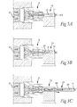
- FIG. 5A-C schematically illustrate one embodiment of a method for manufacturing a blank 23 for a round tool. This embodiment is described using a device in accordance with the device disclosed in FIG. 4A-B , however this description applies to devices in accordance with other embodiments of the invention as well.
- a feed material 21 is provided and is fed through a die 6.
- the feed material 21 comprises a powder mixture comprising cemented carbide for manufacturing a blank for a cemented carbide tool.
- the powder mixture composition for round tools made of other materials is different and well known.
- the feed material 21 is fed into the inlet 8 of the die 6 and through the die 6 by means for feeding the feed material 21.
- Said means for feeding the feed material may comprise one or more of means for compacting, rotating and heating the feed material 21, all well known.
- This extrusion of the feed material 21 through the die 6 forms an extruded material 22 with chip flutes 4 defined by an interior flute-forming surface 7 of the die 6 at the outlet 9 of the die 6.
- internal coolant channels 3 are formed by filaments 16 arranged in the die 6. Due to rotation of the feed material the filaments 16 are twisted and hence the internal coolant channels 3 will be twisted in the extruded material 22 that leaves the die 6.
- the extruded material 22 is allowed to progress in the extrusion direction into the first end 12 of the sleeve 10 to meet the projection 15 of the end member 14 that closes the sleeve in the second end 13 of the sleeve 10. As the extrusion is continued the sleeve 10 fills up.
- the internal coolant channels 3 formed in the above extrusion process coincides with the projection 15. As illustrated in FIG. 5 this may be accomplished by having filaments 16 with a length that overlaps the projection 15 during extrusion. The overlapping filaments 16 may be hold in place by slits in the end portion of the projection 15.
- the extruded material is deformed and the internal coolant channels will be deformed and as the pressure builds up in the sleeve 10 the internal coolant channels will at least partly be closed.
- the end member is kept in the closed position until the sleeve 10 is substantially filled up. This can be controlled e.g. by measuring the pressure in the sleeve 10.
- the sleeve 10 may be provided with openings to help in controlling the deformation and pressure within the sleeve 10 (not shown).
- the extruded material is cut off at the die 6 to create the blank.
- the blank is attached to the end member, which can be used for handling of the blank.
- the cutting off is accomplished by relative movement between the die 6 and the sleeve 10 in a transverse direction T being perpendicular to the extrusion direction E, or at least part of the sleeve 10 or sleeve arrangement, i.e. using the device of FIG. 4B the body 18 is rotated around a revolve axis R.
- the outlet 8 of the die 6 is aligned with an adjacent sleeve 10, preferably without stopping the extrusion process. This adjacent sleeve 10 is closed by a new end member and the above process is repeated.
- the end member is removed from the blank and the blank is subjected to post-treatment including at least sintering.
- the post-treatment may also include drying and machining prior to sintering.
- shank portion have a square cross section or other geometry adapted to fit into a certain tool holder.
Landscapes
- Engineering & Computer Science (AREA)
- Mechanical Engineering (AREA)
- Manufacturing & Machinery (AREA)
- Drilling Tools (AREA)
- Powder Metallurgy (AREA)
Priority Applications (7)
| Application Number | Priority Date | Filing Date | Title |
|---|---|---|---|
| EP11190514.7A EP2596876A1 (en) | 2011-11-24 | 2011-11-24 | Round tool blank and method and device for making the same |
| EP12190331.4A EP2596877B1 (en) | 2011-11-24 | 2012-10-29 | Method and device for manufacturing a blank for a round tool |
| ES12190331.4T ES2466217T3 (es) | 2011-11-24 | 2012-10-29 | Método y dispositivo para fabricar una preforma para una herramienta redonda |
| US13/680,218 US20130136550A1 (en) | 2011-11-24 | 2012-11-19 | Round tool blank and method and device for making the same |
| JP2012255863A JP6092592B2 (ja) | 2011-11-24 | 2012-11-22 | 回転工具のブランクを製造する方法及び装置並びに回転工具のブランク |
| CN201210483665.3A CN103128117B (zh) | 2011-11-24 | 2012-11-23 | 圆化刀具毛坯及用于制造该圆化刀具毛坯的方法和装置 |
| KR1020120133960A KR101949536B1 (ko) | 2011-11-24 | 2012-11-23 | 원형 공구 블랭크와 그 제조 방법 및 기구 |
Applications Claiming Priority (1)
| Application Number | Priority Date | Filing Date | Title |
|---|---|---|---|
| EP11190514.7A EP2596876A1 (en) | 2011-11-24 | 2011-11-24 | Round tool blank and method and device for making the same |
Publications (1)
| Publication Number | Publication Date |
|---|---|
| EP2596876A1 true EP2596876A1 (en) | 2013-05-29 |
Family
ID=47046496
Family Applications (2)
| Application Number | Title | Priority Date | Filing Date |
|---|---|---|---|
| EP11190514.7A Withdrawn EP2596876A1 (en) | 2011-11-24 | 2011-11-24 | Round tool blank and method and device for making the same |
| EP12190331.4A Not-in-force EP2596877B1 (en) | 2011-11-24 | 2012-10-29 | Method and device for manufacturing a blank for a round tool |
Family Applications After (1)
| Application Number | Title | Priority Date | Filing Date |
|---|---|---|---|
| EP12190331.4A Not-in-force EP2596877B1 (en) | 2011-11-24 | 2012-10-29 | Method and device for manufacturing a blank for a round tool |
Country Status (6)
| Country | Link |
|---|---|
| US (1) | US20130136550A1 (ko) |
| EP (2) | EP2596876A1 (ko) |
| JP (1) | JP6092592B2 (ko) |
| KR (1) | KR101949536B1 (ko) |
| CN (1) | CN103128117B (ko) |
| ES (1) | ES2466217T3 (ko) |
Cited By (3)
| Publication number | Priority date | Publication date | Assignee | Title |
|---|---|---|---|---|
| US20160263665A1 (en) * | 2015-03-11 | 2016-09-15 | Kennametal lnc. | Composite blanks and tooling for cutting applications |
| US20160263666A1 (en) * | 2015-03-12 | 2016-09-15 | Kennametal Inc. | Cutting member with coolant delivery |
| CN115889779A (zh) * | 2022-10-25 | 2023-04-04 | 株洲东亚工具有限公司 | 合金粉末压制棒材加工系统 |
Families Citing this family (13)
| Publication number | Priority date | Publication date | Assignee | Title |
|---|---|---|---|---|
| EP2298491B1 (de) * | 2009-09-22 | 2017-06-28 | Firma Gühring oHG | Werkzeug mit Kühlmittelkanälen |
| DE102010028474A1 (de) * | 2010-05-03 | 2011-11-03 | Hilti Aktiengesellschaft | Hohlbohrer und Herstellungsverfahren |
| CN106132608B (zh) | 2014-01-31 | 2018-10-16 | 5Me埃普有限责任公司 | 具有内部冷却腔的旋转切削工具 |
| US10010948B1 (en) * | 2014-10-14 | 2018-07-03 | Matthew W. Hayden | Near-net shaped cutting tools and processes and devices for making the same |
| CN106270504B (zh) * | 2016-09-18 | 2018-06-29 | 辽宁科技大学 | 一种微钻头的微挤压装置及微型钻头的制造方法 |
| DE102017212054B4 (de) * | 2017-07-13 | 2019-02-21 | Kennametal Inc. | Verfahren zur Herstellung eines Schneidkopfes sowie Schneidkopf |
| DE102018202941B4 (de) * | 2018-02-27 | 2024-01-25 | Kennametal Inc. | Verfahren zur Herstellung eines Rohlings aus Extrusionsmasse sowie Extruder |
| EP3626372A1 (en) * | 2018-09-24 | 2020-03-25 | Lamina Technologies SA | Variable core diameter cutting tool and method for producing the same |
| CN112077370A (zh) | 2019-06-13 | 2020-12-15 | 肯纳金属印度有限公司 | 可转位钻头刀片 |
| JP7463674B2 (ja) * | 2019-08-27 | 2024-04-09 | 三菱マテリアル株式会社 | 刃先交換式クーラント孔付きエンドミルのエンドミル本体および刃先交換式クーラント孔付きエンドミル |
| CN113000843A (zh) * | 2021-03-26 | 2021-06-22 | 深圳市注成科技股份有限公司 | 内冷却钻头成型工艺 |
| CN113441761B (zh) * | 2021-06-22 | 2023-04-18 | 哈尔滨瀚成科技有限公司 | 一种内冷钻头制备方法、内冷钻头和加热装置 |
| KR102591490B1 (ko) * | 2022-04-06 | 2023-10-19 | 예상백 | 탄소 섬유 강화 플라스틱용 절삭공구, 및 이의 제조방법 |
Citations (3)
| Publication number | Priority date | Publication date | Assignee | Title |
|---|---|---|---|---|
| US7101167B2 (en) | 1999-06-03 | 2006-09-05 | Seco Tools Ab | Method and a device for manufacturing a tool and a tool made by the method |
| US7296497B2 (en) | 2004-05-04 | 2007-11-20 | Sandvik Intellectual Property Ab | Method and device for manufacturing a drill blank or a mill blank |
| WO2010125555A1 (en) * | 2009-04-26 | 2010-11-04 | Iscar Ltd. | Cutting tool and a process for making such a cutting tool |
Family Cites Families (10)
| Publication number | Priority date | Publication date | Assignee | Title |
|---|---|---|---|---|
| US3242712A (en) * | 1961-12-04 | 1966-03-29 | Gen Dynamics Corp | Apparatus for the forming of articles |
| DE3309860A1 (de) * | 1983-02-08 | 1984-08-09 | Fa. Gottlieb Gühring, 7470 Albstadt | Bohrwerkzeug |
| DE3600681A1 (de) * | 1985-10-31 | 1987-05-07 | Krupp Gmbh | Hartmetall- oder keramikbohrerrohling sowie verfahren und strangpresswerkzeug zu seiner herstellung |
| DE3601385A1 (de) * | 1986-01-18 | 1987-07-23 | Krupp Gmbh | Verfahren zur herstellung von sinterkoerpern mit inneren kanaelen, strangpresswerkzeug zur durchfuehrung des verfahrens und bohrwerkzeug |
| AT400687B (de) * | 1989-12-04 | 1996-02-26 | Plansee Tizit Gmbh | Verfahren und strangpresswerkzeug zur herstellung eines rohlings mit innenliegenden bohrungen |
| SE514558C2 (sv) * | 1999-07-02 | 2001-03-12 | Seco Tools Ab | Metod och anordning för att tillverka ett verktyg |
| SE526650C2 (sv) * | 2003-06-04 | 2005-10-18 | Seco Tools Ab | Verktyg |
| SE527456C2 (sv) * | 2003-07-28 | 2006-03-14 | Sandvik Intellectual Property | Förfarande och anordning för tillverkning genom extrusion av roterande verktyg för spånavskiljande bearbetning och verktyg |
| DE102007042279A1 (de) * | 2007-09-06 | 2009-03-12 | Komet Group Holding Gmbh | Bohrwerkzeug für Werkzeugmaschinen sowie Verfahren zu dessen Herstellung |
| EP2298491B1 (de) * | 2009-09-22 | 2017-06-28 | Firma Gühring oHG | Werkzeug mit Kühlmittelkanälen |
-
2011
- 2011-11-24 EP EP11190514.7A patent/EP2596876A1/en not_active Withdrawn
-
2012
- 2012-10-29 ES ES12190331.4T patent/ES2466217T3/es active Active
- 2012-10-29 EP EP12190331.4A patent/EP2596877B1/en not_active Not-in-force
- 2012-11-19 US US13/680,218 patent/US20130136550A1/en not_active Abandoned
- 2012-11-22 JP JP2012255863A patent/JP6092592B2/ja not_active Expired - Fee Related
- 2012-11-23 CN CN201210483665.3A patent/CN103128117B/zh not_active Expired - Fee Related
- 2012-11-23 KR KR1020120133960A patent/KR101949536B1/ko active IP Right Grant
Patent Citations (3)
| Publication number | Priority date | Publication date | Assignee | Title |
|---|---|---|---|---|
| US7101167B2 (en) | 1999-06-03 | 2006-09-05 | Seco Tools Ab | Method and a device for manufacturing a tool and a tool made by the method |
| US7296497B2 (en) | 2004-05-04 | 2007-11-20 | Sandvik Intellectual Property Ab | Method and device for manufacturing a drill blank or a mill blank |
| WO2010125555A1 (en) * | 2009-04-26 | 2010-11-04 | Iscar Ltd. | Cutting tool and a process for making such a cutting tool |
Cited By (3)
| Publication number | Priority date | Publication date | Assignee | Title |
|---|---|---|---|---|
| US20160263665A1 (en) * | 2015-03-11 | 2016-09-15 | Kennametal lnc. | Composite blanks and tooling for cutting applications |
| US20160263666A1 (en) * | 2015-03-12 | 2016-09-15 | Kennametal Inc. | Cutting member with coolant delivery |
| CN115889779A (zh) * | 2022-10-25 | 2023-04-04 | 株洲东亚工具有限公司 | 合金粉末压制棒材加工系统 |
Also Published As
| Publication number | Publication date |
|---|---|
| CN103128117A (zh) | 2013-06-05 |
| KR101949536B1 (ko) | 2019-02-18 |
| JP6092592B2 (ja) | 2017-03-08 |
| JP2013111743A (ja) | 2013-06-10 |
| CN103128117B (zh) | 2016-04-27 |
| EP2596877B1 (en) | 2014-05-21 |
| EP2596877A1 (en) | 2013-05-29 |
| KR20130057958A (ko) | 2013-06-03 |
| US20130136550A1 (en) | 2013-05-30 |
| ES2466217T3 (es) | 2014-06-09 |
Similar Documents
| Publication | Publication Date | Title |
|---|---|---|
| EP2596877B1 (en) | Method and device for manufacturing a blank for a round tool | |
| KR101166404B1 (ko) | 드릴 블랭크 또는 밀 블랭크를 제조하기 위한 방법 및 장치 | |
| KR101595602B1 (ko) | 절삭 공구 및 그러한 절삭 공구를 제조하기 위한 공정 | |
| EP2808106B1 (en) | Method for manufacturing a cutting insert | |
| US20120079918A1 (en) | Method and device for producing longitudinal components of metal with helical grooves, in particular spiral drill bits or screws | |
| EP1502721B2 (en) | Method of making a rotary tool for chip removing machining | |
| KR101086663B1 (ko) | 회전 공구 및 블랭크 | |
| EP3388227A1 (en) | Compacting device and method for producing a cutting insert green body by compacting a powder | |
| DE3636798A1 (de) | Verfahren zur herstellung von einteiligen gesinterten schneidwerkzeugen in schaftausfuehrung | |
| EP3106240A1 (en) | Rotary extrusion machine | |
| SE526650C2 (sv) | Verktyg | |
| EP4197671A1 (de) | Verfahren zur herstellung eines werkzeugs oder eines bearbeitungsaktiven teils eines werkzeugs und nach diesem verfahren hergestelltes werkzeug | |
| CZ2005751A3 (cs) | Zpusob a zarízení pro výrobu výlisku pro nástroj | |
| DE8628857U1 (de) | Umformwerkzeug zur Herstellung von einteiligen gesinterten Zerspannungswerkzeugen |
Legal Events
| Date | Code | Title | Description |
|---|---|---|---|
| PUAI | Public reference made under article 153(3) epc to a published international application that has entered the european phase |
Free format text: ORIGINAL CODE: 0009012 |
|
| AK | Designated contracting states |
Kind code of ref document: A1 Designated state(s): AL AT BE BG CH CY CZ DE DK EE ES FI FR GB GR HR HU IE IS IT LI LT LU LV MC MK MT NL NO PL PT RO RS SE SI SK SM TR |
|
| AX | Request for extension of the european patent |
Extension state: BA ME |
|
| 17P | Request for examination filed |
Effective date: 20131129 |
|
| RBV | Designated contracting states (corrected) |
Designated state(s): AL AT BE BG CH CY CZ DE DK EE ES FI FR GB GR HR HU IE IS IT LI LT LU LV MC MK MT NL NO PL PT RO RS SE SI SK SM TR |
|
| STAA | Information on the status of an ep patent application or granted ep patent |
Free format text: STATUS: THE APPLICATION IS DEEMED TO BE WITHDRAWN |
|
| 18D | Application deemed to be withdrawn |
Effective date: 20131130 |