EP2596699B1 - Vorrichtung zur Baumschneidung - Google Patents
Vorrichtung zur Baumschneidung Download PDFInfo
- Publication number
- EP2596699B1 EP2596699B1 EP20110009268 EP11009268A EP2596699B1 EP 2596699 B1 EP2596699 B1 EP 2596699B1 EP 20110009268 EP20110009268 EP 20110009268 EP 11009268 A EP11009268 A EP 11009268A EP 2596699 B1 EP2596699 B1 EP 2596699B1
- Authority
- EP
- European Patent Office
- Prior art keywords
- branch
- guide bar
- receiving
- receiving members
- projection portions
- Prior art date
- Legal status (The legal status is an assumption and is not a legal conclusion. Google has not performed a legal analysis and makes no representation as to the accuracy of the status listed.)
- Not-in-force
Links
Images


Classifications
-
- A—HUMAN NECESSITIES
- A01—AGRICULTURE; FORESTRY; ANIMAL HUSBANDRY; HUNTING; TRAPPING; FISHING
- A01G—HORTICULTURE; CULTIVATION OF VEGETABLES, FLOWERS, RICE, FRUIT, VINES, HOPS OR SEAWEED; FORESTRY; WATERING
- A01G3/00—Cutting implements specially adapted for horticultural purposes; Delimbing standing trees
- A01G3/08—Other tools for pruning, branching or delimbing standing trees
- A01G3/085—Motor-driven saws for pruning or branching
- A01G3/086—Chain saws
-
- B—PERFORMING OPERATIONS; TRANSPORTING
- B27—WORKING OR PRESERVING WOOD OR SIMILAR MATERIAL; NAILING OR STAPLING MACHINES IN GENERAL
- B27B—SAWS FOR WOOD OR SIMILAR MATERIAL; COMPONENTS OR ACCESSORIES THEREFOR
- B27B17/00—Chain saws; Equipment therefor
- B27B17/0016—Devices to adapt the chain saw for other purposes, e.g. drilling
-
- B—PERFORMING OPERATIONS; TRANSPORTING
- B27—WORKING OR PRESERVING WOOD OR SIMILAR MATERIAL; NAILING OR STAPLING MACHINES IN GENERAL
- B27B—SAWS FOR WOOD OR SIMILAR MATERIAL; COMPONENTS OR ACCESSORIES THEREFOR
- B27B17/00—Chain saws; Equipment therefor
- B27B17/0083—Attachments for guiding or supporting chain saws during operation
Definitions
- the present invention relates to an apparatus for tree pruning capable of efficiently cutting large branches and small branches at high positions of trees, as well as hedges, and particularly to an apparatus for tree pruning of a type in which branch-receiving members are mounted on a guide bar in order to prevent small branches to be cut from being repelled by a saw chain.
- powered pruners and general-purpose chain saws have generally been used to cut large branches (tree branches having diameters of approximately 10 mm or more).
- large branches tree branches having diameters of approximately 10 mm or more.
- the branch-receiving member has an attachment base portion attached to a side surface of a guide bar and branch-receiving projection portions which are continuous to the attachment base portion and which project above and below the guide bar.
- the branch-receiving projection portions are provided continuously to the attachment base portion through outward bending portions.
- Patent Document 2 discloses a chain saw having tapered branch-receiving projection portions.
- Patent Document 3 discloses that the branch-receiving members are inclined in the direction of rotation of the saw chain.
- the conventional chain saws for pruning ( DE A 100 35 832 , DE U 298 16 909 ) have improved performance in cutting small branches owing to the provision of the branch-receiving members to the guide bar.
- the improvement is still insufficient.
- branch clogging and catching of the branch-receiving members occur not a few times in operations in which an operator on the ground prunes branches at high positions of a tree, i.e., in operations of pruning branches far away from the operator, so that the pruning operation is often difficult.
- the present invention has been made in view of the above-described problem, and an object of the present invention is to provide an apparatus for tree pruning capable of efficiently cutting not only large branches, but also small branches without aid of any other apparatus, and effectively reducing unpruned branches as well as branch clogging and catching of the branch-receiving members, so that the workability of pruning trees at high positions can be improved.
- an apparatus for tree pruning of the present invention basically comprises: a plate-shaped guide bar; an endless circular saw chain set around the guide bar and configured to be rotated; and a plurality of branch-receiving members mounted on side surfaces of the guide bar at predetermined intervals in a longitudinal direction of the guide bar and configured to prevent a small branch to be cut from being repelled by the saw chain, wherein the branch-receiving members each have an attachment base portion attached to a side surface of the guide bar and branch-receiving projection portions which are continuous to the attachment base portion through an outward bending portion and which project above and below the guide bar, the branch-receiving members are mounted on both left and right side surfaces of the guide bar, such that the branch-receiving projection portions face each other across the saw chain, wherein projecting heights of the branch-receiving members, from the guide bar, of the branch-receiving projection portions of the branch-receiving members in a left and right pair are different from each other and
- the branch-receiving projection portion has a rear end surface portion which is linear and inclined rearward, and a front end surface portion which is shaped into an arc in order to reduce incidence of catching of a branch.
- rear end surface portions of the branch-receiving projection portions of the branch-receiving members in a left and right pair are placed at the same position in a direction of rotation of the saw chain.
- the branch-receiving members are detachably mounted on the guide bar, and pitch intervals of the branch-receiving members in the longitudinal direction of the guide bar are optionally changeable.
- the rear end surface portions of the branch-receiving projection portions arranged to face each other are configured to receive both sides of a potion of a small branch to be cut, and the rear end surface portions are inclined rearward. Hence, the ability to hold the small branch is improved, so that the small branch is less likely to be repelled.
- one of the projecting heights, from the guide bar, of the branch-receiving projection portions of the branch-receiving members in the left and right pair arranged to face each other is higher than the other one of the projecting heights.
- branch-receiving projection portions of the branch-receiving members mounted on one side surface (the other side surface) of the guide bar are alternately high and low in the longitudinal direction of the guide bar. This also makes it possible to further reduce branch clogging and catching of the branch-receiving members.
- the positions of attachment of the branch-receiving members i.e., pitch intervals of the branch-receiving members in the longitudinal direction of the guide bar, are optionally changeable. This also makes it possible to further improve the workability of pruning.
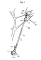
- Fig. 1 is a view showing how a pruning operation is performed by using one embodiment of an apparatus for tree pruning according to the present invention.
- Figs. 2A and 2B are respectively a side view and a plan view showing the embodiment of the apparatus for tree pruning according to the present invention.
- the apparatus for tree pruning 10 shown in Fig. 1 has an operation rod 15 in which a transmission shaft 16 is inserted.
- a transmission box 17 is connected to a front end of the operation rod 15 with a connection joint 19.
- the transmission box 17 houses a gear train and a sprocket wheel.
- a plate-shaped guide bar 20 projecting frontward is provided at a right-front end portion of the transmission box 17.
- An endless circular saw chain 22 is set around the guide bar 20 and the sprocket wheel in the transmission box 17.
- a small air-cooled two-stroke gasoline engine 11 is attached to a rear end of the operation rod 15.
- the gasoline engine 11 is a motor for rotating the saw chain 22 by means of the transmission shaft 16 and the transmission box 17.
- a recoil starter 11s and a fuel tank 11f are provided to the gasoline engine 11.
- a semi-circular ring handle 12 having a grip is provided in the vicinity of the rear end of the operation rod 15.
- the handle 12 is used to swing a guide bar 20 portion, around which the saw chain 22 is set, upward, downward, leftward, rightward, frontward, and rearward (in general, the handle 12 is gripped by the right hand and a lower portion of the operation rod 15 above the handle 12 is gripped by the left hand).
- the branch-receiving members 30 and 40 are mounted on one side surface and the other side surface of the guide bar 20 at predetermined intervals (pitch intervals P) in a longitudinal direction of the guide bar 20 in order to prevent a small branch to be cut from being repelled by the saw chain 22.
- the branch-receiving members can be classified into two kinds, namely, high projecting branch-receiving members 30 and low projecting branch-receiving members 40. Note that a long hole 27 used for attachment of the guide bar 20 to the transmission box 17 is provided in the vicinity of the rear end of the guide bar 20.
- Each of the high projecting branch-receiving members 30 has an attachment base portion 32 attached to a side surface of the guide bar 20, and branch-receiving projection portions 35 and 36 which are continuous to the attachment base portion 32 through outward bending portions 33, and which project above and below the guide bar 20, respectively.
- the low projecting branch-receiving members 40 have a similar shape to that of the high projecting branch-receiving members 30, but have a smaller length than the high projecting branch-receiving members 30.
- Each of the low projecting branch-receiving members 40 has an attachment base portion 42 attached to a side surface of the guide bar 20, and branch-receiving projection portions 45 and 46 which are continuous to the attachment base portion 42 through outward bending portions 43, and which project above and below the guide bar 20, respectively (the branch-receiving projection portions 45 and 46 have a smaller projecting height than the branch-receiving projection portions 35 and 36 of the high projecting branch-receiving members 30).
- rear end surface portions 35a, 36a, 45a, and 46a of the branch-receiving projection portions 35, 36, 45, and 46 are each linear and inclined rearward with respect to a direction of rotation of the saw chain (a rearward inclination angle is shown by ⁇ in Fig. 3A ), and front end surface portions of the branch-receiving projection portions 35, 36, 45, and 46 are each shaped into an arc in order to reduce incidence of catching of a branch. It has been found out from experimental manufacture and the like that the optimum rearward inclination angle ⁇ is approximately 80°.
- a high projecting branch-receiving member 30 on one side surface of the guide bar 20 and a low projecting branch-receiving member 40 on the other side surface thereof are fixed together by being fastened with two upper and lower bolts and the like 26 such that the branch-receiving projection portions 35 and 45 face each other and the branch-receiving projection portions 36 and 46 face each other across the saw chain 22.
- the branch-receiving members 30 and 40 in each left and right pair projecting heights, from the guide bar 20, of the branch-receiving projection portions 35 and 45 are different from each other, and projecting heights, from the guide bar 20, of the branch-receiving projection portions 36 and 46 are different from each other.
- the rear end surface portions 35a and 45a of the branch-receiving projection portions 35 and 45 are placed at the same position and the rear end surface portions 36a and 46a of the branch-receiving projection portions 36 and 46 are placed at the same position with respect to the direction of rotation of the saw chain 22.
- a high projecting branch-receiving member 30, a low projecting branch-receiving member 40, and a high projecting branch-receiving member 30 are arranged on one side surface of the guide bar 20 in this order in the longitudinal direction of the guide bar 20.
- a low projecting branch-receiving member 40, a high projecting branch-receiving member 30, and a low projecting branch-receiving member 40 are arranged on the other side surface of the guide bar 20, i.e., on the opposite side from the high projecting branch-receiving member 30, the low projecting branch-receiving member 40, and the high projecting branch-receiving member 30.
- the branch-receiving projection portions of the branch-receiving members mounted on one side surface (another side surface) of the guide bar 20 are alternately high and low in a longitudinal direction of the guide bar 20.
- the saw chain 22 is rotated by driving the engine 11, and a small branch K to be cut is received by the rear end surface portions 35a and 45a or 36a and 46a of the branch-receiving projection portions 35 and 45 or 36 and 46, so that the small branch K can be cut (see Fig. 2A and 3A ).
- the rear end surface portions 35a and 45a or 36a and 46a of the branch-receiving projection portions 35 and 45 or 36 and 46 arranged to face each other are configured to receive both sides of a potion of a small branch K to be cut, and the rear end surface portions 35a and 45a or 36a and 46a are inclined rearward.
- the ability to hold the small branch K is improved, so that the small branch K is less likely to be repelled.
- pairs of upper and lower bolt-and-the-like through holes 28 are provided in the guide bar 20 at predetermined intervals in the longitudinal direction of the guide bar 20.
- the through holes 28 are used for attaching the branch-receiving members 30 and 40 detachably from the guide bar 20. Accordingly, the positions of attachment of the branch-receiving members 30 and 40, i.e., the pitch intervals P of the branch-receiving members 30 and 40 in the longitudinal direction of the guide bar 20 are optionally changeable.
- the branch-receiving members 30 and 40 are arranged to face each other on both side surfaces of the guide bar 20.
- one of the projecting heights, from the guide bar 20, of the branch-receiving projection portions 35 and 45 is higher than the other one of the projecting heights
- one of the projecting heights, from the guide bar 20, of the branch-receiving projection portions 36 and 46 is higher than the other one of the projecting heights.
- the branch-receiving projection portions 35 and 45 are alternately high and low and the branch-receiving projection portions 36 and 46 are alternately high and low in the longitudinal direction of the guide bar 20. This also makes it possible to further reduce unpruned branches as well as branch clogging and catching of the branch-receiving members 30 and 40.
- the positions of attachment of the branch-receiving members 30 and 40 i.e., pitch intervals P of the branch-receiving members 30 and 40 in the longitudinal direction of the guide bar 20, are optionally changeable. This also makes it possible to further improve the workability of pruning.
- 10 apparatus for tree pruning, 11 ... small air-cooled two-stroke gasoline engine (motor), 15 ... operation rod, 17 ... transmission box, 20 ... guide bar, 22 ... saw chain, 26 ... bolt and the like, 28 ... through hole, 30 ... high projecting branch-receiving member, 32 ... attachment base portion, 35 and 36 ... branch-receiving projection portion, 40 ... low projecting branch-receiving member, 42 ... attachment base portion, 45 and 46 ... branch-receiving projection portion.
Landscapes
- Life Sciences & Earth Sciences (AREA)
- Forests & Forestry (AREA)
- Engineering & Computer Science (AREA)
- Mechanical Engineering (AREA)
- Wood Science & Technology (AREA)
- Biodiversity & Conservation Biology (AREA)
- Ecology (AREA)
- Environmental Sciences (AREA)
- Scissors And Nippers (AREA)
- Sawing (AREA)
Claims (4)
- Vorrichtung zum Baumschneiden (10), die Folgendes aufweist:eine plattenförmige Führungsstange (20);eine endlose Kreissägenkette (22), die rund um die Führungsstange (20) herumgelegt und ausgestaltet ist, um gedreht zu werden; undeine Vielzahl von astaufnehmenden Elementen (30;40), die auf Seitenflächen der Führungsstange (20) in zuvor festgelegten Abständen auf der Führungsstange (20) in einer Längsrichtung der Führungsstange (20) angebracht und so ausgestaltet sind, dass sie das Zurückstoßen eines abzuschneidenden kleinen Astes durch die Sägekette (22) verhindern, wobeian den astaufnehmenden Elementen (30;40) jeweils einen Befestigungsbasisabschnitt (32; 42) aufweisen, der an einer Seitenfläche der Führungsstange (20) befestigt ist, und astaufnehmende Vorsprungabschnitte (35,36;45,46), die zu dem Befestigungsbasisabschnitt (32;42) über einen nach außen gebogenen Abschnitt durchgängig sind, und die oberhalb und unterhalb der Führungsstange (20) hervorstehen,die astaufnehmenden Elemente (30;40) auf beiden, den linken und rechten Seitenflächen der Führungsstange (20) derart angebracht sind, dass die astaufnehmenden Vorsprungabschnitte (35,36;45,46) einander bezüglich der Sägekette (22) zugewandt sind,
dadurch gekennzeichnet, dasssich von der Führungsstange ausgehende Höhen der astaufnehmenden Elemente (30;40), der astaufnehmenden Vorsprungabschnitte der astaufnehmenden Elemente in einem linken und rechten Paar voneinander unterscheiden, und dassdie astaufnehmenden Vorsprungabschnitte (35,36;45,46) der auf einer Seitenfläche der Führungsstange angebrachten astaufnehmenden Elemente (30,40) in Längsrichtung der Führungsstange (20) wechselweise hoch und niedrig sind. - Vorrichtung zum Baumschneiden nach Anspruch 1, wobei in jedem der astaufnehmenden Elemente (30;40) in einer Drehrichtung der Sägekette (22) gesehen der astaufnehmende Vorsprungsabschnitt (35,36;45,46) einen hinteren Endflächenabschnitt aufweist, der linear und nach hinten geneigt ist, und einen vorderen Endflächenabschnitt, der bogenförmig ausgebildet ist, um Vorkommnisse des Verfangens eines Astes (K) zu verringern.
- Vorrichtung zum Baumschneiden nach Anspruch 1, wobei hintere Endflächenabschnitte der astaufnehmenden Vorsprungsabschnitte (35,36;45,46) der astaufnehmenden Elemente (30;40) in einem linken und rechten Paar in einer Drehrichtung der Sägekette (22) in der gleichen Position angeordnet sind.
- Vorrichtung zum Baumschneiden nach Anspruch 1, wobei die astaufnehmenden Elemente (30;40) entfernbar auf der Führungsstange (20) angebracht sind, und
die Abstandsintervalle der astaufnehmenden Elemente (30;40) in Längsrichtung der Führungsstange (20) optional änderbar sind.
Priority Applications (2)
| Application Number | Priority Date | Filing Date | Title |
|---|---|---|---|
| EP20110009268 EP2596699B1 (de) | 2011-11-22 | 2011-11-22 | Vorrichtung zur Baumschneidung |
| AU2012101644A AU2012101644A4 (en) | 2011-11-22 | 2012-11-02 | Apparatus for tree pruning |
Applications Claiming Priority (1)
| Application Number | Priority Date | Filing Date | Title |
|---|---|---|---|
| EP20110009268 EP2596699B1 (de) | 2011-11-22 | 2011-11-22 | Vorrichtung zur Baumschneidung |
Publications (2)
| Publication Number | Publication Date |
|---|---|
| EP2596699A1 EP2596699A1 (de) | 2013-05-29 |
| EP2596699B1 true EP2596699B1 (de) | 2014-07-02 |
Family
ID=47321072
Family Applications (1)
| Application Number | Title | Priority Date | Filing Date |
|---|---|---|---|
| EP20110009268 Not-in-force EP2596699B1 (de) | 2011-11-22 | 2011-11-22 | Vorrichtung zur Baumschneidung |
Country Status (2)
| Country | Link |
|---|---|
| EP (1) | EP2596699B1 (de) |
| AU (1) | AU2012101644A4 (de) |
Cited By (1)
| Publication number | Priority date | Publication date | Assignee | Title |
|---|---|---|---|---|
| CN105940974A (zh) * | 2016-05-26 | 2016-09-21 | 国网河南省电力公司南阳供电公司 | 一种配电网输电线路树枝清除装置 |
Families Citing this family (11)
| Publication number | Priority date | Publication date | Assignee | Title |
|---|---|---|---|---|
| CN106358781A (zh) * | 2016-10-12 | 2017-02-01 | 国网江苏省电力公司徐州供电公司 | 带电高压线路高枝修剪气动工具 |
| CN106613405A (zh) * | 2017-01-10 | 2017-05-10 | 郭建文 | 一种高速快捷方便使用的剪枝器 |
| CN110249781A (zh) * | 2019-06-28 | 2019-09-20 | 江苏盐西高新绿色产业发展有限公司 | 一种园林绿化草坪修剪设备 |
| CN110771377B (zh) * | 2019-11-23 | 2021-10-15 | 徐小娟 | 一种用于林业作用的手持式电动修枝器 |
| CN111955197B (zh) * | 2020-07-06 | 2022-07-26 | 国网浙江瑞安市供电有限责任公司 | 一种绝缘型高处树枝抓握器 |
| KR102290994B1 (ko) * | 2020-10-19 | 2021-08-20 | (주)대원이앤씨 | 조형목을 단기간 내에 대량 제조하는 방법 |
| CN112369241B (zh) * | 2020-10-21 | 2023-08-22 | 新疆农垦科学院 | 一种枣树修枝刀盘及其构成的立体式分层仿形枣树修剪装置 |
| KR102310006B1 (ko) * | 2021-05-14 | 2021-10-07 | 홍예은 | 관상수목 형성방법 |
| CN115024113B (zh) * | 2022-07-06 | 2023-09-22 | 重庆市林业科学研究院 | 一种森林抚育整枝修剪器 |
| CN116326363A (zh) * | 2022-12-13 | 2023-06-27 | 国网湖南省电力有限公司 | 一种配电线路沿线树/竹修剪装置及其应用方法 |
| CN119156988B (zh) * | 2024-11-15 | 2025-05-02 | 内蒙古自治区林业和草原监测规划院 | 一种森林抚育修剪装置 |
Family Cites Families (9)
| Publication number | Priority date | Publication date | Assignee | Title |
|---|---|---|---|---|
| US2642901A (en) | 1950-10-06 | 1953-06-23 | Ernest A Hayden | Clipper and mower attachment for chain saws |
| US2925105A (en) | 1956-12-18 | 1960-02-16 | Ernest A Hayden | Chain saw equipped with bar stops |
| US5671537A (en) * | 1995-09-29 | 1997-09-30 | Dofredo; Nestor V. | Chain saw attachment for use in trimming shrubbery |
| US5669145A (en) * | 1996-04-15 | 1997-09-23 | Skripsky; Harold O. | Chainsaw attachment |
| US5878499A (en) | 1997-05-08 | 1999-03-09 | King; Pat | Trimmer bar for a chain saw |
| DE29816909U1 (de) * | 1998-09-15 | 1999-02-18 | Scheeren, Udo, 41238 Mönchengladbach | Anbaugerät für Kettensägen |
| DE10035832A1 (de) * | 2000-07-18 | 2002-01-31 | Horst Gollnick | Sägeanschläge für Führungsschienen von Motorkettensägen |
| US6536119B1 (en) * | 2001-06-29 | 2003-03-25 | Alvin W. Carr | Hedge cutting system |
| US20070271798A1 (en) * | 2006-05-26 | 2007-11-29 | Jules Webb | Brush cutting attachment for chainsaw bar |
-
2011
- 2011-11-22 EP EP20110009268 patent/EP2596699B1/de not_active Not-in-force
-
2012
- 2012-11-02 AU AU2012101644A patent/AU2012101644A4/en not_active Ceased
Cited By (2)
| Publication number | Priority date | Publication date | Assignee | Title |
|---|---|---|---|---|
| CN105940974A (zh) * | 2016-05-26 | 2016-09-21 | 国网河南省电力公司南阳供电公司 | 一种配电网输电线路树枝清除装置 |
| CN105940974B (zh) * | 2016-05-26 | 2019-02-05 | 国网河南省电力公司南阳供电公司 | 一种配电网输电线路树枝清除装置 |
Also Published As
| Publication number | Publication date |
|---|---|
| EP2596699A1 (de) | 2013-05-29 |
| AU2012101644A4 (en) | 2012-12-06 |
Similar Documents
| Publication | Publication Date | Title |
|---|---|---|
| EP2596699B1 (de) | Vorrichtung zur Baumschneidung | |
| JP7431666B2 (ja) | 園芸用トリマ | |
| CN203261732U (zh) | 手持植物修剪器 | |
| KR101129771B1 (ko) | 가지치기 전동톱 | |
| US5669145A (en) | Chainsaw attachment | |
| US9468143B2 (en) | Grass blade for a trimmer | |
| US4912848A (en) | Power tool handle | |
| JP2009171947A (ja) | 伐採機 | |
| CN1195400C (zh) | 修剪机及其防护装置 | |
| FR2940591A3 (fr) | Secateur electrique | |
| US20070113925A1 (en) | Felling Head With Offset Arms | |
| CN103200810B (zh) | 联合收割机 | |
| KR200441100Y1 (ko) | 시금치 수확장치 | |
| US20060283023A1 (en) | Cutting apparatus | |
| KR101129793B1 (ko) | 가지치기용 전동톱 | |
| CN203860101U (zh) | 园林树木修剪工具 | |
| CN105538437A (zh) | 散生竹采伐锯 | |
| JP2011050360A (ja) | 刈払機 | |
| CN105409609A (zh) | 一种手持电动剪锯一体机 | |
| CN105522624A (zh) | 丛生竹采伐锯 | |
| JP2017118846A (ja) | 刈込機 | |
| JP7045678B2 (ja) | 草刈剪定機 | |
| JP2017108644A (ja) | 歩行型草刈機および草刈方法 | |
| CN101554111B (zh) | 沙地步进式割灌木机 | |
| WO2013081450A2 (en) | A cutting device |
Legal Events
| Date | Code | Title | Description |
|---|---|---|---|
| PUAI | Public reference made under article 153(3) epc to a published international application that has entered the european phase |
Free format text: ORIGINAL CODE: 0009012 |
|
| AK | Designated contracting states |
Kind code of ref document: A1 Designated state(s): AL AT BE BG CH CY CZ DE DK EE ES FI FR GB GR HR HU IE IS IT LI LT LU LV MC MK MT NL NO PL PT RO RS SE SI SK SM TR |
|
| AX | Request for extension of the european patent |
Extension state: BA ME |
|
| 17P | Request for examination filed |
Effective date: 20131129 |
|
| RBV | Designated contracting states (corrected) |
Designated state(s): AL AT BE BG CH CY CZ DE DK EE ES FI FR GB GR HR HU IE IS IT LI LT LU LV MC MK MT NL NO PL PT RO RS SE SI SK SM TR |
|
| RIC1 | Information provided on ipc code assigned before grant |
Ipc: A01G 3/08 20060101AFI20131217BHEP Ipc: B27B 17/00 20060101ALI20131217BHEP |
|
| GRAP | Despatch of communication of intention to grant a patent |
Free format text: ORIGINAL CODE: EPIDOSNIGR1 |
|
| INTG | Intention to grant announced |
Effective date: 20140129 |
|
| RAP1 | Party data changed (applicant data changed or rights of an application transferred) |
Owner name: YAMABIKO CORPORATION |
|
| RIN1 | Information on inventor provided before grant (corrected) |
Inventor name: KANO, YOSHIAKI Inventor name: HAYASHI, SYUNGO Inventor name: NAGAISHI, HIDEKI Inventor name: ITO, TAKU |
|
| GRAS | Grant fee paid |
Free format text: ORIGINAL CODE: EPIDOSNIGR3 |
|
| GRAA | (expected) grant |
Free format text: ORIGINAL CODE: 0009210 |
|
| AK | Designated contracting states |
Kind code of ref document: B1 Designated state(s): AL AT BE BG CH CY CZ DE DK EE ES FI FR GB GR HR HU IE IS IT LI LT LU LV MC MK MT NL NO PL PT RO RS SE SI SK SM TR |
|
| REG | Reference to a national code |
Ref country code: GB Ref legal event code: FG4D |
|
| REG | Reference to a national code |
Ref country code: CH Ref legal event code: EP Ref country code: AT Ref legal event code: REF Ref document number: 675367 Country of ref document: AT Kind code of ref document: T Effective date: 20140715 |
|
| REG | Reference to a national code |
Ref country code: IE Ref legal event code: FG4D |
|
| REG | Reference to a national code |
Ref country code: DE Ref legal event code: R096 Ref document number: 602011008042 Country of ref document: DE Effective date: 20140814 |
|
| REG | Reference to a national code |
Ref country code: AT Ref legal event code: MK05 Ref document number: 675367 Country of ref document: AT Kind code of ref document: T Effective date: 20140702 |
|
| REG | Reference to a national code |
Ref country code: NL Ref legal event code: VDEP Effective date: 20140702 |
|
| REG | Reference to a national code |
Ref country code: LT Ref legal event code: MG4D |
|
| PG25 | Lapsed in a contracting state [announced via postgrant information from national office to epo] |
Ref country code: SE Free format text: LAPSE BECAUSE OF FAILURE TO SUBMIT A TRANSLATION OF THE DESCRIPTION OR TO PAY THE FEE WITHIN THE PRESCRIBED TIME-LIMIT Effective date: 20140702 Ref country code: ES Free format text: LAPSE BECAUSE OF FAILURE TO SUBMIT A TRANSLATION OF THE DESCRIPTION OR TO PAY THE FEE WITHIN THE PRESCRIBED TIME-LIMIT Effective date: 20140702 Ref country code: GR Free format text: LAPSE BECAUSE OF FAILURE TO SUBMIT A TRANSLATION OF THE DESCRIPTION OR TO PAY THE FEE WITHIN THE PRESCRIBED TIME-LIMIT Effective date: 20141003 Ref country code: FI Free format text: LAPSE BECAUSE OF FAILURE TO SUBMIT A TRANSLATION OF THE DESCRIPTION OR TO PAY THE FEE WITHIN THE PRESCRIBED TIME-LIMIT Effective date: 20140702 Ref country code: LT Free format text: LAPSE BECAUSE OF FAILURE TO SUBMIT A TRANSLATION OF THE DESCRIPTION OR TO PAY THE FEE WITHIN THE PRESCRIBED TIME-LIMIT Effective date: 20140702 Ref country code: NO Free format text: LAPSE BECAUSE OF FAILURE TO SUBMIT A TRANSLATION OF THE DESCRIPTION OR TO PAY THE FEE WITHIN THE PRESCRIBED TIME-LIMIT Effective date: 20141002 Ref country code: PT Free format text: LAPSE BECAUSE OF FAILURE TO SUBMIT A TRANSLATION OF THE DESCRIPTION OR TO PAY THE FEE WITHIN THE PRESCRIBED TIME-LIMIT Effective date: 20141103 Ref country code: CZ Free format text: LAPSE BECAUSE OF FAILURE TO SUBMIT A TRANSLATION OF THE DESCRIPTION OR TO PAY THE FEE WITHIN THE PRESCRIBED TIME-LIMIT Effective date: 20140702 Ref country code: BG Free format text: LAPSE BECAUSE OF FAILURE TO SUBMIT A TRANSLATION OF THE DESCRIPTION OR TO PAY THE FEE WITHIN THE PRESCRIBED TIME-LIMIT Effective date: 20141002 |
|
| PG25 | Lapsed in a contracting state [announced via postgrant information from national office to epo] |
Ref country code: AT Free format text: LAPSE BECAUSE OF FAILURE TO SUBMIT A TRANSLATION OF THE DESCRIPTION OR TO PAY THE FEE WITHIN THE PRESCRIBED TIME-LIMIT Effective date: 20140702 Ref country code: IS Free format text: LAPSE BECAUSE OF FAILURE TO SUBMIT A TRANSLATION OF THE DESCRIPTION OR TO PAY THE FEE WITHIN THE PRESCRIBED TIME-LIMIT Effective date: 20141102 Ref country code: CY Free format text: LAPSE BECAUSE OF FAILURE TO SUBMIT A TRANSLATION OF THE DESCRIPTION OR TO PAY THE FEE WITHIN THE PRESCRIBED TIME-LIMIT Effective date: 20140702 Ref country code: NL Free format text: LAPSE BECAUSE OF FAILURE TO SUBMIT A TRANSLATION OF THE DESCRIPTION OR TO PAY THE FEE WITHIN THE PRESCRIBED TIME-LIMIT Effective date: 20140702 Ref country code: LV Free format text: LAPSE BECAUSE OF FAILURE TO SUBMIT A TRANSLATION OF THE DESCRIPTION OR TO PAY THE FEE WITHIN THE PRESCRIBED TIME-LIMIT Effective date: 20140702 Ref country code: RS Free format text: LAPSE BECAUSE OF FAILURE TO SUBMIT A TRANSLATION OF THE DESCRIPTION OR TO PAY THE FEE WITHIN THE PRESCRIBED TIME-LIMIT Effective date: 20140702 Ref country code: HR Free format text: LAPSE BECAUSE OF FAILURE TO SUBMIT A TRANSLATION OF THE DESCRIPTION OR TO PAY THE FEE WITHIN THE PRESCRIBED TIME-LIMIT Effective date: 20140702 Ref country code: PL Free format text: LAPSE BECAUSE OF FAILURE TO SUBMIT A TRANSLATION OF THE DESCRIPTION OR TO PAY THE FEE WITHIN THE PRESCRIBED TIME-LIMIT Effective date: 20140702 |
|
| REG | Reference to a national code |
Ref country code: DE Ref legal event code: R097 Ref document number: 602011008042 Country of ref document: DE |
|
| PG25 | Lapsed in a contracting state [announced via postgrant information from national office to epo] |
Ref country code: DK Free format text: LAPSE BECAUSE OF FAILURE TO SUBMIT A TRANSLATION OF THE DESCRIPTION OR TO PAY THE FEE WITHIN THE PRESCRIBED TIME-LIMIT Effective date: 20140702 Ref country code: RO Free format text: LAPSE BECAUSE OF FAILURE TO SUBMIT A TRANSLATION OF THE DESCRIPTION OR TO PAY THE FEE WITHIN THE PRESCRIBED TIME-LIMIT Effective date: 20140702 Ref country code: SK Free format text: LAPSE BECAUSE OF FAILURE TO SUBMIT A TRANSLATION OF THE DESCRIPTION OR TO PAY THE FEE WITHIN THE PRESCRIBED TIME-LIMIT Effective date: 20140702 Ref country code: EE Free format text: LAPSE BECAUSE OF FAILURE TO SUBMIT A TRANSLATION OF THE DESCRIPTION OR TO PAY THE FEE WITHIN THE PRESCRIBED TIME-LIMIT Effective date: 20140702 |
|
| PLBE | No opposition filed within time limit |
Free format text: ORIGINAL CODE: 0009261 |
|
| STAA | Information on the status of an ep patent application or granted ep patent |
Free format text: STATUS: NO OPPOSITION FILED WITHIN TIME LIMIT |
|
| 26N | No opposition filed |
Effective date: 20150407 |
|
| PG25 | Lapsed in a contracting state [announced via postgrant information from national office to epo] |
Ref country code: BE Free format text: LAPSE BECAUSE OF NON-PAYMENT OF DUE FEES Effective date: 20141130 Ref country code: MC Free format text: LAPSE BECAUSE OF FAILURE TO SUBMIT A TRANSLATION OF THE DESCRIPTION OR TO PAY THE FEE WITHIN THE PRESCRIBED TIME-LIMIT Effective date: 20140702 Ref country code: LU Free format text: LAPSE BECAUSE OF FAILURE TO SUBMIT A TRANSLATION OF THE DESCRIPTION OR TO PAY THE FEE WITHIN THE PRESCRIBED TIME-LIMIT Effective date: 20141122 |
|
| REG | Reference to a national code |
Ref country code: CH Ref legal event code: PL |
|
| PG25 | Lapsed in a contracting state [announced via postgrant information from national office to epo] |
Ref country code: CH Free format text: LAPSE BECAUSE OF NON-PAYMENT OF DUE FEES Effective date: 20141130 Ref country code: LI Free format text: LAPSE BECAUSE OF NON-PAYMENT OF DUE FEES Effective date: 20141130 |
|
| REG | Reference to a national code |
Ref country code: IE Ref legal event code: MM4A |
|
| PG25 | Lapsed in a contracting state [announced via postgrant information from national office to epo] |
Ref country code: IE Free format text: LAPSE BECAUSE OF NON-PAYMENT OF DUE FEES Effective date: 20141122 |
|
| REG | Reference to a national code |
Ref country code: FR Ref legal event code: PLFP Year of fee payment: 5 |
|
| PG25 | Lapsed in a contracting state [announced via postgrant information from national office to epo] |
Ref country code: SI Free format text: LAPSE BECAUSE OF FAILURE TO SUBMIT A TRANSLATION OF THE DESCRIPTION OR TO PAY THE FEE WITHIN THE PRESCRIBED TIME-LIMIT Effective date: 20140702 |
|
| PG25 | Lapsed in a contracting state [announced via postgrant information from national office to epo] |
Ref country code: SM Free format text: LAPSE BECAUSE OF FAILURE TO SUBMIT A TRANSLATION OF THE DESCRIPTION OR TO PAY THE FEE WITHIN THE PRESCRIBED TIME-LIMIT Effective date: 20140702 |
|
| PG25 | Lapsed in a contracting state [announced via postgrant information from national office to epo] |
Ref country code: BE Free format text: LAPSE BECAUSE OF FAILURE TO SUBMIT A TRANSLATION OF THE DESCRIPTION OR TO PAY THE FEE WITHIN THE PRESCRIBED TIME-LIMIT Effective date: 20140702 Ref country code: HU Free format text: LAPSE BECAUSE OF FAILURE TO SUBMIT A TRANSLATION OF THE DESCRIPTION OR TO PAY THE FEE WITHIN THE PRESCRIBED TIME-LIMIT; INVALID AB INITIO Effective date: 20111122 Ref country code: MT Free format text: LAPSE BECAUSE OF FAILURE TO SUBMIT A TRANSLATION OF THE DESCRIPTION OR TO PAY THE FEE WITHIN THE PRESCRIBED TIME-LIMIT Effective date: 20140702 Ref country code: TR Free format text: LAPSE BECAUSE OF FAILURE TO SUBMIT A TRANSLATION OF THE DESCRIPTION OR TO PAY THE FEE WITHIN THE PRESCRIBED TIME-LIMIT Effective date: 20140702 |
|
| REG | Reference to a national code |
Ref country code: FR Ref legal event code: PLFP Year of fee payment: 6 |
|
| REG | Reference to a national code |
Ref country code: FR Ref legal event code: PLFP Year of fee payment: 7 |
|
| PG25 | Lapsed in a contracting state [announced via postgrant information from national office to epo] |
Ref country code: MK Free format text: LAPSE BECAUSE OF FAILURE TO SUBMIT A TRANSLATION OF THE DESCRIPTION OR TO PAY THE FEE WITHIN THE PRESCRIBED TIME-LIMIT Effective date: 20140702 |
|
| PG25 | Lapsed in a contracting state [announced via postgrant information from national office to epo] |
Ref country code: AL Free format text: LAPSE BECAUSE OF FAILURE TO SUBMIT A TRANSLATION OF THE DESCRIPTION OR TO PAY THE FEE WITHIN THE PRESCRIBED TIME-LIMIT Effective date: 20140702 |
|
| PGFP | Annual fee paid to national office [announced via postgrant information from national office to epo] |
Ref country code: DE Payment date: 20181120 Year of fee payment: 8 |
|
| PGFP | Annual fee paid to national office [announced via postgrant information from national office to epo] |
Ref country code: GB Payment date: 20181120 Year of fee payment: 8 Ref country code: IT Payment date: 20181126 Year of fee payment: 8 Ref country code: FR Payment date: 20181123 Year of fee payment: 8 |
|
| REG | Reference to a national code |
Ref country code: DE Ref legal event code: R119 Ref document number: 602011008042 Country of ref document: DE |
|
| GBPC | Gb: european patent ceased through non-payment of renewal fee |
Effective date: 20191122 |
|
| PG25 | Lapsed in a contracting state [announced via postgrant information from national office to epo] |
Ref country code: GB Free format text: LAPSE BECAUSE OF NON-PAYMENT OF DUE FEES Effective date: 20191122 Ref country code: IT Free format text: LAPSE BECAUSE OF NON-PAYMENT OF DUE FEES Effective date: 20191122 Ref country code: FR Free format text: LAPSE BECAUSE OF NON-PAYMENT OF DUE FEES Effective date: 20191130 Ref country code: DE Free format text: LAPSE BECAUSE OF NON-PAYMENT OF DUE FEES Effective date: 20200603 |