EP2595225A1 - Method for producing fuel cell catalyst, fuel cell catalyst, and use thereof - Google Patents
Method for producing fuel cell catalyst, fuel cell catalyst, and use thereof Download PDFInfo
- Publication number
- EP2595225A1 EP2595225A1 EP11806580.4A EP11806580A EP2595225A1 EP 2595225 A1 EP2595225 A1 EP 2595225A1 EP 11806580 A EP11806580 A EP 11806580A EP 2595225 A1 EP2595225 A1 EP 2595225A1
- Authority
- EP
- European Patent Office
- Prior art keywords
- fuel cell
- cell catalyst
- metal
- catalyst
- oxycarbonitride
- Prior art date
- Legal status (The legal status is an assumption and is not a legal conclusion. Google has not performed a legal analysis and makes no representation as to the accuracy of the status listed.)
- Granted
Links
Images
Classifications
-
- B—PERFORMING OPERATIONS; TRANSPORTING
- B01—PHYSICAL OR CHEMICAL PROCESSES OR APPARATUS IN GENERAL
- B01J—CHEMICAL OR PHYSICAL PROCESSES, e.g. CATALYSIS OR COLLOID CHEMISTRY; THEIR RELEVANT APPARATUS
- B01J27/00—Catalysts comprising the elements or compounds of halogens, sulfur, selenium, tellurium, phosphorus or nitrogen; Catalysts comprising carbon compounds
- B01J27/24—Nitrogen compounds
-
- H—ELECTRICITY
- H01—ELECTRIC ELEMENTS
- H01M—PROCESSES OR MEANS, e.g. BATTERIES, FOR THE DIRECT CONVERSION OF CHEMICAL ENERGY INTO ELECTRICAL ENERGY
- H01M4/00—Electrodes
- H01M4/86—Inert electrodes with catalytic activity, e.g. for fuel cells
- H01M4/88—Processes of manufacture
-
- H—ELECTRICITY
- H01—ELECTRIC ELEMENTS
- H01M—PROCESSES OR MEANS, e.g. BATTERIES, FOR THE DIRECT CONVERSION OF CHEMICAL ENERGY INTO ELECTRICAL ENERGY
- H01M4/00—Electrodes
- H01M4/86—Inert electrodes with catalytic activity, e.g. for fuel cells
- H01M4/90—Selection of catalytic material
-
- H—ELECTRICITY
- H01—ELECTRIC ELEMENTS
- H01M—PROCESSES OR MEANS, e.g. BATTERIES, FOR THE DIRECT CONVERSION OF CHEMICAL ENERGY INTO ELECTRICAL ENERGY
- H01M4/00—Electrodes
- H01M4/86—Inert electrodes with catalytic activity, e.g. for fuel cells
- H01M4/90—Selection of catalytic material
- H01M4/9016—Oxides, hydroxides or oxygenated metallic salts
-
- H—ELECTRICITY
- H01—ELECTRIC ELEMENTS
- H01M—PROCESSES OR MEANS, e.g. BATTERIES, FOR THE DIRECT CONVERSION OF CHEMICAL ENERGY INTO ELECTRICAL ENERGY
- H01M8/00—Fuel cells; Manufacture thereof
- H01M8/10—Fuel cells with solid electrolytes
- H01M2008/1095—Fuel cells with polymeric electrolytes
-
- Y—GENERAL TAGGING OF NEW TECHNOLOGICAL DEVELOPMENTS; GENERAL TAGGING OF CROSS-SECTIONAL TECHNOLOGIES SPANNING OVER SEVERAL SECTIONS OF THE IPC; TECHNICAL SUBJECTS COVERED BY FORMER USPC CROSS-REFERENCE ART COLLECTIONS [XRACs] AND DIGESTS
- Y02—TECHNOLOGIES OR APPLICATIONS FOR MITIGATION OR ADAPTATION AGAINST CLIMATE CHANGE
- Y02E—REDUCTION OF GREENHOUSE GAS [GHG] EMISSIONS, RELATED TO ENERGY GENERATION, TRANSMISSION OR DISTRIBUTION
- Y02E60/00—Enabling technologies; Technologies with a potential or indirect contribution to GHG emissions mitigation
- Y02E60/30—Hydrogen technology
- Y02E60/50—Fuel cells
Definitions
- the present invention relates to a method for producing a fuel cell catalyst, a fuel cell catalyst, and uses thereof; and particularly relates to a method and the like for producing a fuel cell catalyst comprising a metal oxycarbonitride.
- Fuel cells are categorized into various types based on the types of electrolyte and the types of electrode used therein. Typical types are alkaline, phosphoric acid, molten carbonate, solid electrolyte, and polymer electrolyte fuel cells.
- polymer electrolyte fuel cells that can operate at temperatures ranging from low temperatures (about -40°C) to about 120°C have attracted attention and, in recent years, are being progressively developed and practically used as low pollution power sources for automobiles.
- the polymer electrolyte fuel cells are expected to be used as automobile drive sources or stationary power sources. However, use in these applications requires long-term durability.
- Polymer electrolyte fuel cells have a solid polymer electrolyte sandwiched between an anode and a cathode.
- a fuel is fed to the anode, and oxygen or air is fed to the cathode, whereby oxygen is reduced at the cathode to produce electricity.
- the fuel is primarily hydrogen, methanol, or the like.
- a layer containing a catalyst (hereinafter, also referred to as a "fuel cell catalyst layer") is conventionally provided on the surface of a cathode (an air electrode) or the surface of an anode (a fuel electrode) of the fuel cell.
- noble metals are generally used as the catalysts.
- platinum that is stable at high potential and has high catalytic activity is most frequently used.
- platinum is expensive and exists in a limited amount.
- Patent Literature 1 WO2009/031383
- Patent Literature 2 WO2009/107518
- Patent Literature 1 or Patent Literature 2 present applicant expresses extremely high catalytic activity compared to conventional platinum alternate catalysts and, from this perspective, is better suited for practical use. However, there is a need for further improvement with regards to the maintenance of durability.
- the present inventors studied diligently to solve the conventional problems in the art and, as a result of diligent research, have discovered a method for producing a catalyst whereby durability can be maintained by subjecting the catalyst to a simple treatment.
- the present invention has been completed based on this finding.
- an object of the present invention is to provide a method for producing a fuel cell catalyst comprising a metal oxycarbonitride having durability that is superior to that of conventional fuel cell catalysts.
- the present invention relates to, for example, the following [1] to [11].
- a fuel cell catalyst containing a metal oxycarbonitride that has durability superior to that of conventional fuel cell catalysts, and a fuel cell using said catalyst can be provided. More specifically, a fuel cell catalyst comprising a metal oxycarbonitride and a fuel cell using said catalyst can be provided in which maximum power density is not prone to decline even after going through repeated changes in current and/or voltage.
- a method for producing a fuel cell catalyst containing a metal oxycarbonitride according to the present invention includes:
- the metal oxycarbonitride is produced by heating a metal carbonitride in an inert gas containing oxygen gas.
- a conventional method can be used as the method for producing the metal oxycarbonitride by heating a metal carbonitride in an inert gas containing oxygen gas.
- Examples thereof include a method for producing a niobium oxycarbonitride by heat treating niobium carbonitride in an inert gas containing oxygen gas (see WO2009/031383 ) and a method for producing a titanium oxycarbonitride by heat treating titanium carbonitride in an inert gas containing oxygen gas (see WO2009/107518 ).
- the inert gas containing oxygen gas also contains hydrogen gas, but in the present invention, the inert gas may not contain hydrogen gas.
- oxycarbonitrides of other metal elements may be produced by using carbonitrides of other metals (e. g. iron, lanthanum, and the like) together with or in place of the niobium carbonitride or the titanium carbonitride.
- carbonitrides of other metals e. g. iron, lanthanum, and the like
- metal element when the metal element is represented as "M”, "metal oxycarbonitride", when the composition formula is MC x N y O z , refers to a compound expressed by composition formula MC x N y O z and/or a mixture comprising a metal oxide, a metal carbide, a metal nitride, a metal carbonitride, a metal oxycarbide, or a metal oxynitride that is expressed by the composition formula MC x N y O z as a whole.
- the mixture may or may not comprise a compound expressed by MC x N y O z .
- the metal oxycarbonitride is often obtained in the form of a sintered body.
- the method for producing a fuel cell catalyst according to the present invention preferably comprises a step of crushing the sintered body prior to the contacting step. If this step is included, catalyst area of the produced fuel cell catalyst will increase and the catalytic performance thereof will be superior.
- a conventional method can be used as the method for crushing the metal oxycarbonitride obtained in the step of producing the metal oxycarbonitride. Examples thereof include a method recited in WO2009/031383 .
- the metal oxycarbonitride is brought into contact with an acidic solution.
- the metal oxycarbonitride is preferably obtained by crushing the metal oxycarbonitride obtained in the step of producing the metal oxycarbonitride.
- Examples of the acid include hydrogen chloride, sulfuric acid, citric acid, acetic acid, hydrofluoric acid, phosphoric acid, and nitric acid. Of these, hydrogen chloride, sulfuric acid, citric acid, acetic acid, nitric acid, and phosphoric acid are preferable. A single acid may be used, or a combination of two or more acids may be used.
- a solvent of the acidic solution is preferably a hydrophilic solvent; more preferably a compound having hydroxyl groups, a compound having ether bonds, or water; even more preferably an alcohol such as methanol, ethanol, propanol, isopropanol, butanol, or the like, a cyclic ether such as THF (tetrahydrofuran) or the like, or water; and yet even more preferably water.
- a single solvent may be used, or a combination of two or more solvents may be used.
- a concentration of the acid in the acidic solution at 25°C is preferably from 0.01 to 15N, more preferably from 0.05 to 10N, and even more preferably from 0.1 to 5N. It is preferable that the concentration of the acid is within this range because the dissolution of the metal component in the fuel cell catalyst will be prone to be uniform.
- a temperature at the contacting step (hereinafter also referred to as the "contacting temperature”) is preferably from 15 to 100°C, more preferably from 20 to 80°C, and even more preferably from 25 to 70°C. It is preferable that the contacting temperature be within this range because the dissolution of the metal component in the fuel cell catalyst will be rapid and the acidic solution will not be prone to evaporation.
- a time of the contacting step (hereinafter also referred to as the "contacting time") is preferably from 0.1 to 500 hours, more preferably from 5 to 300 hours, and even more preferably from 12 to 150 hours. It is preferable that the contacting time is within this range because the dissolution of the metal component in the fuel cell catalyst will proceed in a uniform manner.
- the metal oxycarbonitride and the acidic solution are brought into contact with each other by placing both components in a container.
- the components are preferably stirred at this time.
- a ratio of the acidic solution to the metal oxycarbonitride is dependent on the types used thereof but, typically, preferably from 100 to 50,000 mL and more preferably from 1,000 to 10,000 mL of the acidic solution is included per 1 g of the metal oxycarbonitride.
- the contacting step is completed when the metal oxycarbonitride is recovered.
- methods for recovering the metal oxycarbonitride include conventional techniques such as suction filtration, centrifugation, and the like.
- the production method of the present invention preferably comprises a step of washing the metal oxycarbonitride after the contacting step.
- the eluted metal component which is a cause of electrolyte membrane deterioration, can be more effectively removed from the metal oxycarbonitride after the contacting step.
- the washing step is performed by, for example, bringing a cleansing liquid and the metal oxycarbonitride having gone through the contacting step into contact with each other by placing both components in a container.
- the components are preferably stirred at this time.
- Examples of the cleansing liquid include water and the like.
- the production method of the present invention preferably comprises a step of drying the metal oxycarbonitride after the contacting step, and more preferably comprises the drying step after the washing step.
- drying in the drying step examples include drying in a vacuum (drying under reduced pressure), drying by heating, and the like.
- the drying step is preferably performed at a temperature of 100°C or less.
- a fuel cell catalyst comprising a metal oxycarbonitride with a low dissolved metal content, specifically a fuel cell catalyst comprising a metal oxycarbonitride having a dissolved metal content that is not more than 15 % by mass, preferably from 0.01 to 15 % by mass, more preferably from 0.05 to 10 % by mass, and even more preferably from 0.1 to 7 % by mass is produced. If the dissolved content is within this range, a fuel cell catalyst with superior durability and a fuel cell using this catalyst can be obtained.
- Dissolved metal content mass of metal dissolved when immersing the fuel cell catalyst in a 1 ⁇ N sulfuric acid aqueous solution at 60 ⁇ °C for 150 hours / mass of fuel cell catalyst before imersing ⁇ 100.
- the "mass of metal dissolved" in the formula above is a mass that is measured according to a method used in the Examples described below.
- the fuel cell catalyst according to the present invention is a catalyst that is produced through the production method according to the present invention as described above.
- the fuel cell catalyst is preferably a powder because catalytic performance will be high.
- the fuel cell catalyst can be used as an alternate to a platinum catalyst.
- a fuel cell catalyst layer according to the present invention comprises the fuel cell catalyst described above.
- the fuel cell catalyst layer preferably further comprises electron conductive powder.
- the reduction current can be further increased. It is thought that the electron conductive powder can increase the reduction current because said electron conductive powder allows the catalyst to form an electrical bond that induces an electrochemical reaction.
- the electron conductive particles are usually used as a carrier of the catalyst.
- the fuel cell catalyst layer may be used as an anode catalyst layer or a cathode catalyst layer.
- the fuel cell catalyst layer contains the catalyst that has high oxygen reducing activity and is resistant to corrosion in acidic electrolytes even at high potential. Accordingly, the fuel cell catalyst layer is suited for use as a catalyst layer provided in a cathode of a fuel cell (as a cathode catalyst layer), and is particularly suited for use as a catalyst layer provided on a cathode of a membrane electrode assembly included in a polymer electrolyte fuel cell.
- An electrode according to the present invention comprises the fuel cell catalyst layer and a porous support layer.
- the electrode may be used as a cathode or an anode.
- the electrode has superior durability and high catalytic performance and, therefore, exhibits greater benefits when used as a cathode.
- the membrane electrode assembly according to the present invention comprises a cathode, an anode and an electrolyte membrane interposed between the cathode and the anode.
- the cathode and/or the anode is the electrode according to the present invention.
- the electrolyte membrane is a perfluorosulfonic acid electrolyte membrane, a hydrocarbon electrolyte membrane, or the like.
- a polymer microporous membrane impregnated with a liquid electrolyte, a porous membrane filled with a polymer electrolyte, or the like may also be used.
- the fuel cell according to the present invention comprises the membrane electrode assembly as described above.
- the electrode reaction in fuel cells takes place at a so-called three-phase interface (electrolyte-electrocatalyst-reaction gas).
- the fuel cells are categorized according to the electrolytes and the like used therein into several types such as molten carbonate fuel cells (MCFC), phosphoric acid fuel cells (PAFC), solid oxide fuel cells (SOFC), and polymer electrolyte fuel cells (PEFC). Polymer electrolyte fuel cells are preferable as the fuel cell according to the present invention.
- Dissolved metal content mass of metal dissolved when immersing the fuel cell catalyst in a 1 ⁇ N sulfuric acid aqueous solution at 60 °C for 150 hours / mass of fuel cell catalyst before immersing ⁇ 100
- the mass of metal dissolved was measured via ICP-atomic emission spectrometry after immersing the fuel cell catalyst, removing 10 mL of the sulfuric acid aqueous solution supernatent and, thereafter filtering using a 0.2 ⁇ m filter.
- the measurement apparatus was a VISTA-PRO (manufactured by SII), and the same was used to detect the following wavelengths.
- Fe 259.088 nm
- Nb 295.088 nm
- La 379.477 nm
- Ti 334.941 nm.
- Temperatures of the single cells fabricated in the Examples and Comparative Examples, anode humidifiers, and cathode humidifiers were regulated to 90°C, 95°C, and 65°C, respectively. Hydrogen was supplied to the anode side as a fuel at a flow rate of 1 L/min, and oxygen was supplied to the cathode side as an oxidizing agent at a flow rate of 2 L/min. While applying a back pressure of 300 kPa to both the sides, the current-voltage property of the single cells was measured, and the maximum power density was calculated from the resulting current-voltage property curve.
- 1.18 g of an iron and niobium oxycarbonitride (1) was obtained by heating 1.05 g of the obtained powdered carbonitride (1) in a rotary kiln at 900°C for seven hours under a flow of a nitrogen gas comprising 0.75% by volume of oxygen gas and 4% by volume of hydrogen gas.
- the iron and niobium oxycarbonitride (1) was milled using a planetary ball mill (Premium 7, manufactured by Fritsch; rotating radius: 2.3 cm, orbital radius: 16.3 cm) as described below.
- a planetary ball mill Premium 7, manufactured by Fritsch; rotating radius: 2.3 cm, orbital radius: 16.3 cm
- the iron and niobium oxycarbonitride (1) was pulverized under the following conditions: rotation/revolution speed: 700 rpm, orbital revolution speed: 350 rpm, rotating centrifugal acceleration: 12.6 G, orbital centrifugal acceleration: 22.3 G, pulverizing time: 5 minutes. Thereby a fuel cell catalyst (1) was obtained.
- the fuel cell catalyst (1) was water-cooled in the zirconia mill container. After the water-cooling, the zirconia balls were separated from the acetonitrile and the fuel cell catalyst (1). Furthermore, the acetonitrile was removed from the acetonitrile and the fuel cell catalyst (1) using a rotary evaporator so as to isolate the fuel cell catalyst (1).
- a fuel cell catalyst (2) was obtained by filtrating/separating by suction filtration, washing using distilled water and, thereafter, drying under vacuum for three hours at 60°C.
- Dissolved metal content of the fuel cell catalyst (2) is shown in Table 1.
- a gas diffusion layer (carbon paper TGP-H-060, manufactured by Toray Industries Inc.) was immersed in acetone for 30 seconds, degreased, and dried. Then, the gas diffusion layer was immersed in an aqueous 10% polytetrafluoroethylene (hereinafter also referred to as "PTFE”) solution for 30 seconds. The immersed product was dried at room temperature, and then was heated at 350°C for one hour. Thereby, a water-repellent gas diffusion layer having PTFE dispersed in the carbon paper (hereinafter also referred to as "GDL”) was obtained.
- PTFE polytetrafluoroethylene
- the GDL described above was formed into the size of 5 cm ⁇ 5 cm, and the surface thereof was coated with the anode ink (1) prepared in 1 above using an automatic spray-coating apparatus (manufactured by San-Ei Tech Ltd.) at 80°C.
- an electrode having an anode catalyst layer (1) in which the amount of platinum (Pt) per unit area was 1 mg/cm 2 was fabricated.
- 0.284 g of the fuel cell catalyst (2) prepared in 1 above, and 0.071 g of carbon black as an electron conductive material were added to 50 ml of 2-propanol (manufactured by Wako Pure Chemical Industries, Ltd.). Then, to this mixture, 2.84 g of an aqueous solution containing a proton conductive material (NAFION®, 0.142 g; or, rather, 5% NAFION® aqueous solution, manufactured by Wako Pure Chemical Industries, Ltd.) was added. The resultant solution was mixed using an ultrasonic wave dispersion machine (UT-106H, manufactured by Sharp Manufacturing Systems Corporation) for one hour. Thereby, a cathode ink (1) was prepared.
- NAFION® a proton conductive material
- a gas diffusion layer (carbon paper TGP-H-060, manufactured by Toray Industries Inc.) was immersed in acetone for 30 seconds, degreased, and dried. Then, the gas diffusion layer was immersed in an aqueous 10% polytetrafluoroethylene (hereinafter also referred to as "PTFE”) solution for 30 seconds. The immersed product was dried at room temperature, and then was heated at 350°C for one hour. Thereby, a water-repellent gas diffusion layer having PTFE dispersed in the carbon paper (hereinafter also referred to as "GDL”) was obtained.
- PTFE polytetrafluoroethylene
- the GDL described above was formed into the size of 5 cm ⁇ 5 cm, and the surface thereof was coated with the cathode ink (1) prepared in 2 above using an automatic spray-coating apparatus (manufactured by San-Ei Tech Ltd.) at 80°C.
- an electrode having a cathode catalyst layer (1) in which the total amount of the fuel cell catalyst (2) and carbon black per unit area was 5 mg/cm 2 was fabricated.
- MEA membrane electrode assembly
- NAFION membrane N-117 manufactured by DuPont was used as an electrolyte membrane.
- the MEA (1) in which the electrolyte membrane was interposed between the cathode and the anode was fabricated as described below.
- the electrolyte membrane was heated at 80°C for one hour in a 3% hydrogen peroxide solution and then was heated at 80°C for one hour in pure water.
- the electrolyte membrane was heated at 80°C for one hour in a 1M sulfuric acid aqueous solution and then was heated at 80°C for one hour in pure water.
- An MEA (1) was fabricated by sandwiching the electrolyte membrane, from which moisture was removed, between the cathode and the anode and, in such a state, the cathode catalyst layer (1) and the anode catalyst layer (1) were thermally contact bonded using a hot pressing machine at 140°C at 3 MPa for 6 minutes so as to adhere to the electrolyte membrane.
- a single cell (1) (25 cm 2 ) of a polymer electrolyte fuel cell was fabricated by sandwiching the MEA (1), fabricated in 2-4 above, between two sealing materials (gaskets), two separators each having a gas flow passage, two current collectors, and two rubber heaters, and fixing with a bolt such that the pressure of contacted surface would be a prescribed value (4N).
- Dissolved metal content of the fuel cell catalyst (3) is shown in Table 1.
- single cell (2) a single cell of a polymer electrolyte fuel cell (hereinafter referred to as "single cell (2)") was fabricated in the same manner described in Example 1. Note that an MEA that was used for fabricating the single cell (2) is referred to as "MEA (2)".
- TiO 2 titanium oxide
- carbon black XC-72, manufactured by Cabot Corporation
- lanthanum oxide La 2 O 3
- 1.18 g of a titanium and lanthanum oxycarbonitride (2) was obtained by heating 1.0 g of the obtained powdered carbonitride (2) at 900°C for four hours in a tubular furnace under a flow of a nitrogen gas comprising 1% by volume of oxygen gas and 1% by volume of hydrogen gas.
- This titanium and lanthanum oxycarbonitride (2) was pulverized in the same manner described in "1. Preparation of fuel cell catalyst" in Example 1 in order to obtain a fuel cell catalyst (4).
- a fuel cell catalyst (5) was obtained by filtrating/separating by suction filtration, washing using distilled water and, thereafter, drying under vacuum for three hours at 60°C.
- Dissolved metal content of the fuel cell catalyst (5) is shown in Table 1.
- single cell (3) a single cell of a polymer electrolyte fuel cell (hereinafter referred to as "single cell (3)”) was fabricated in the same manner described in Example 1. Note that an MEA that was used for fabricating the single cell (3) is referred to as "MEA (3)".
- Dissolved metal content of the fuel cell catalyst (6) is shown in Table 1.
- single cell (4) a single cell of a polymer electrolyte fuel cell (hereinafter referred to as "single cell (4)") was fabricated in the same manner described in Example 1. Note that an MEA that was used for fabricating the single cell (4) is referred to as "MEA (4)".
- single cell (5) a single cell of a polymer electrolyte fuel cell (hereinafter referred to as "single cell (5)") was fabricated in the same manner described in Example 1. Note that an MEA that was used for fabricating the single cell (5) is referred to as "MEA (5)".
- single cell (6) a single cell of a polymer electrolyte fuel cell (hereinafter referred to as "single cell (6)") was fabricated in the same manner described in Example 1. Note that an MEA that was used for fabricating the single cell (6) is referred to as "MEA (6)".
Landscapes
- Chemical & Material Sciences (AREA)
- Engineering & Computer Science (AREA)
- Chemical Kinetics & Catalysis (AREA)
- Electrochemistry (AREA)
- General Chemical & Material Sciences (AREA)
- Materials Engineering (AREA)
- Manufacturing & Machinery (AREA)
- Organic Chemistry (AREA)
- Inert Electrodes (AREA)
- Fuel Cell (AREA)
- Catalysts (AREA)
Abstract
Description
- The present invention relates to a method for producing a fuel cell catalyst, a fuel cell catalyst, and uses thereof; and particularly relates to a method and the like for producing a fuel cell catalyst comprising a metal oxycarbonitride.
- Fuel cells are categorized into various types based on the types of electrolyte and the types of electrode used therein. Typical types are alkaline, phosphoric acid, molten carbonate, solid electrolyte, and polymer electrolyte fuel cells. In particular, polymer electrolyte fuel cells that can operate at temperatures ranging from low temperatures (about -40°C) to about 120°C have attracted attention and, in recent years, are being progressively developed and practically used as low pollution power sources for automobiles. The polymer electrolyte fuel cells are expected to be used as automobile drive sources or stationary power sources. However, use in these applications requires long-term durability.
- Polymer electrolyte fuel cells have a solid polymer electrolyte sandwiched between an anode and a cathode. A fuel is fed to the anode, and oxygen or air is fed to the cathode, whereby oxygen is reduced at the cathode to produce electricity. The fuel is primarily hydrogen, methanol, or the like.
- To increase the reaction rate in the fuel cell and enhance the energy conversion efficiency of the fuel cell, a layer containing a catalyst (hereinafter, also referred to as a "fuel cell catalyst layer") is conventionally provided on the surface of a cathode (an air electrode) or the surface of an anode (a fuel electrode) of the fuel cell.
- Here, noble metals are generally used as the catalysts. Of the noble metals, platinum that is stable at high potential and has high catalytic activity is most frequently used. However, platinum is expensive and exists in a limited amount.
- Therefore, in recent years, research into the development of an alternative catalyst to platinum has been actively conducted. The present applicant has, in fact, proposed a catalyst comprising a niobium or titanium oxycarbonitride (e.g. see
WO2009/031383 (Patent Literature 1) andWO2009/107518 (Patent Literature 2)). -
- Patent Literature 1:
WO2009/031383 - Patent Literature 2:
WO2009/107518 - Practical use of fuel cell catalysts requires high initial characteristics and the capacity to maintain stable catalytic activity over an extended period of time, that is, durability.
- The fuel cell catalyst recited in
Patent Literature 1 or Patent Literature 2 (present applicant) expresses extremely high catalytic activity compared to conventional platinum alternate catalysts and, from this perspective, is better suited for practical use. However, there is a need for further improvement with regards to the maintenance of durability. - The present inventors studied diligently to solve the conventional problems in the art and, as a result of diligent research, have discovered a method for producing a catalyst whereby durability can be maintained by subjecting the catalyst to a simple treatment. The present invention has been completed based on this finding.
- That is, an object of the present invention is to provide a method for producing a fuel cell catalyst comprising a metal oxycarbonitride having durability that is superior to that of conventional fuel cell catalysts.
- The present invention relates to, for example, the following [1] to [11].
-
- [1] A method for producing a fuel cell catalyst containing a metal oxycarbonitride, the method comprising: a step of producing a metal oxycarbonitride by heating a metal carbonitride in an inert gas containing oxygen gas; and
a step of bringing the metal oxycarbonitride into contact with an acidic solution. -
- [2] The method as described in [1] above, wherein the acidic solution is an aqueous solution of at least one type of acid selected from the group consisting of hydrogen chloride, sulfuric acid, citric acid, and acetic acid.
-
- [3] The method as described in [1] or [2] above, wherein the contacting step is performed under the following conditions: Temperature: 15 to 100°C
-
- [4] A fuel cell catalyst produced via the production method as described in any one of [1] to [3] above, wherein the metal oxycarbonitride at least comprises niobium or titanium.
-
- [5] The fuel cell catalyst as described in [4] above, having not more than 15 % by mass of dissolved metal content as defined by the following formula:


-
- [6] A fuel cell catalyst layer comprising the fuel cell catalyst as described in [4] or [5] above.
-
- [7] The fuel cell catalyst layer as described in [6] above, further comprising electron conductive particles.
-
- [8] An electrode comprising a fuel cell catalyst layer and a porous support layer, wherein the fuel cell catalyst layer is a fuel cell catalyst layer as described in [6] or [7] above.
-
- [9] A membrane electrode assembly comprising a cathode, an anode and an electrolyte membrane interposed between the cathode and the anode, wherein the cathode and/or the anode is the electrode as described in [8] above.
-
- [10] A fuel cell comprising the membrane electrode assembly as described in [9] above.
-
- [11] A polymer electrolyte fuel cell comprising the membrane electrode assembly as described in [9] above.
- According to the present invention, a fuel cell catalyst containing a metal oxycarbonitride that has durability superior to that of conventional fuel cell catalysts, and a fuel cell using said catalyst can be provided. More specifically, a fuel cell catalyst comprising a metal oxycarbonitride and a fuel cell using said catalyst can be provided in which maximum power density is not prone to decline even after going through repeated changes in current and/or voltage.
-
-
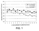
FIG. 1 is a graph showing evaluations of durability of single cells of polymer electrolyte fuel cells in Examples 1 and 2 and Comparative Example 1. (Results of evaluating the durability of iron and niobium oxycarbonitrides) -
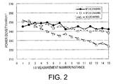
FIG. 2 is a graph showing evaluations of durability of single cells of polymer electrolyte fuel cells in Examples 3 and 4 and Comparative Example 2. (Results of evaluating the durability of titanium and lanthanum oxycarbonitrides) - A method for producing a fuel cell catalyst containing a metal oxycarbonitride according to the present invention includes:
- a step of producing a metal oxycarbonitride by heating a metal carbonitride in an inert gas containing oxygen gas; and
- a step of bringing the metal oxycarbonitride into contact with an acidic solution.
- In the step of producing the metal oxycarbonitride, the metal oxycarbonitride is produced by heating a metal carbonitride in an inert gas containing oxygen gas.
- A conventional method can be used as the method for producing the metal oxycarbonitride by heating a metal carbonitride in an inert gas containing oxygen gas. Examples thereof include a method for producing a niobium oxycarbonitride by heat treating niobium carbonitride in an inert gas containing oxygen gas (see
WO2009/031383 ) and a method for producing a titanium oxycarbonitride by heat treating titanium carbonitride in an inert gas containing oxygen gas (seeWO2009/107518 ). Note that in these methods, the inert gas containing oxygen gas also contains hydrogen gas, but in the present invention, the inert gas may not contain hydrogen gas. - Additionally, in these production methods, oxycarbonitrides of other metal elements may be produced by using carbonitrides of other metals (e. g. iron, lanthanum, and the like) together with or in place of the niobium carbonitride or the titanium carbonitride.
- In the present invention, when the metal element is represented as "M", "metal oxycarbonitride", when the composition formula is MCxNyOz, refers to a compound expressed by composition formula MCxNyOz and/or a mixture comprising a metal oxide, a metal carbide, a metal nitride, a metal carbonitride, a metal oxycarbide, or a metal oxynitride that is expressed by the composition formula MCxNyOz as a whole. However, in the case of the latter, the mixture may or may not comprise a compound expressed by MCxNyOz.
- In the step of producing the metal oxycarbonitride, the metal oxycarbonitride is often obtained in the form of a sintered body.
- The method for producing a fuel cell catalyst according to the present invention preferably comprises a step of crushing the sintered body prior to the contacting step. If this step is included, catalyst area of the produced fuel cell catalyst will increase and the catalytic performance thereof will be superior.
- A conventional method can be used as the method for crushing the metal oxycarbonitride obtained in the step of producing the metal oxycarbonitride. Examples thereof include a method recited in
WO2009/031383 . - In the contacting step, the metal oxycarbonitride is brought into contact with an acidic solution.
- As described above, the metal oxycarbonitride is preferably obtained by crushing the metal oxycarbonitride obtained in the step of producing the metal oxycarbonitride.
- Examples of the acid include hydrogen chloride, sulfuric acid, citric acid, acetic acid, hydrofluoric acid, phosphoric acid, and nitric acid. Of these, hydrogen chloride, sulfuric acid, citric acid, acetic acid, nitric acid, and phosphoric acid are preferable. A single acid may be used, or a combination of two or more acids may be used.
- A solvent of the acidic solution is preferably a hydrophilic solvent; more preferably a compound having hydroxyl groups, a compound having ether bonds, or water; even more preferably an alcohol such as methanol, ethanol, propanol, isopropanol, butanol, or the like, a cyclic ether such as THF (tetrahydrofuran) or the like, or water; and yet even more preferably water. A single solvent may be used, or a combination of two or more solvents may be used.
- A concentration of the acid in the acidic solution at 25°C is preferably from 0.01 to 15N, more preferably from 0.05 to 10N, and even more preferably from 0.1 to 5N. It is preferable that the concentration of the acid is within this range because the dissolution of the metal component in the fuel cell catalyst will be prone to be uniform.
- Additionally, a temperature at the contacting step (hereinafter also referred to as the "contacting temperature") is preferably from 15 to 100°C, more preferably from 20 to 80°C, and even more preferably from 25 to 70°C. It is preferable that the contacting temperature be within this range because the dissolution of the metal component in the fuel cell catalyst will be rapid and the acidic solution will not be prone to evaporation.
- A time of the contacting step (hereinafter also referred to as the "contacting time") is preferably from 0.1 to 500 hours, more preferably from 5 to 300 hours, and even more preferably from 12 to 150 hours. It is preferable that the contacting time is within this range because the dissolution of the metal component in the fuel cell catalyst will proceed in a uniform manner.
- In the contacting step, for example, the metal oxycarbonitride and the acidic solution are brought into contact with each other by placing both components in a container. The components are preferably stirred at this time.
- A ratio of the acidic solution to the metal oxycarbonitride is dependent on the types used thereof but, typically, preferably from 100 to 50,000 mL and more preferably from 1,000 to 10,000 mL of the acidic solution is included per 1 g of the metal oxycarbonitride.
- The contacting step is completed when the metal oxycarbonitride is recovered. Examples of methods for recovering the metal oxycarbonitride include conventional techniques such as suction filtration, centrifugation, and the like.
- The production method of the present invention preferably comprises a step of washing the metal oxycarbonitride after the contacting step.
- By providing the washing step, the eluted metal component, which is a cause of electrolyte membrane deterioration, can be more effectively removed from the metal oxycarbonitride after the contacting step.
- The washing step is performed by, for example, bringing a cleansing liquid and the metal oxycarbonitride having gone through the contacting step into contact with each other by placing both components in a container. The components are preferably stirred at this time.
- Examples of the cleansing liquid include water and the like.
- The production method of the present invention preferably comprises a step of drying the metal oxycarbonitride after the contacting step, and more preferably comprises the drying step after the washing step.
- Examples of the form of the drying in the drying step include drying in a vacuum (drying under reduced pressure), drying by heating, and the like.
- From the perspective of preventing agglomeration of the fuel cell catalyst, the drying step is preferably performed at a temperature of 100°C or less.
- According to the production method of the present invention, a fuel cell catalyst comprising a metal oxycarbonitride with a low dissolved metal content, specifically a fuel cell catalyst comprising a metal oxycarbonitride having a dissolved metal content that is not more than 15 % by mass, preferably from 0.01 to 15 % by mass, more preferably from 0.05 to 10 % by mass, and even more preferably from 0.1 to 7 % by mass is produced. If the dissolved content is within this range, a fuel cell catalyst with superior durability and a fuel cell using this catalyst can be obtained.
- The dissolved metal content as mentioned above is defined by the following formula:

- The "mass of metal dissolved" in the formula above is a mass that is measured according to a method used in the Examples described below.
- The fuel cell catalyst according to the present invention is a catalyst that is produced through the production method according to the present invention as described above.
- The fuel cell catalyst is preferably a powder because catalytic performance will be high.
- The fuel cell catalyst can be used as an alternate to a platinum catalyst.
- A fuel cell catalyst layer according to the present invention comprises the fuel cell catalyst described above.
- The fuel cell catalyst layer preferably further comprises electron conductive powder. When the fuel cell catalyst layer comprising the catalyst further comprises the electron conductive powder, the reduction current can be further increased. It is thought that the electron conductive powder can increase the reduction current because said electron conductive powder allows the catalyst to form an electrical bond that induces an electrochemical reaction.
- The electron conductive particles are usually used as a carrier of the catalyst.
- The fuel cell catalyst layer may be used as an anode catalyst layer or a cathode catalyst layer. The fuel cell catalyst layer contains the catalyst that has high oxygen reducing activity and is resistant to corrosion in acidic electrolytes even at high potential. Accordingly, the fuel cell catalyst layer is suited for use as a catalyst layer provided in a cathode of a fuel cell (as a cathode catalyst layer), and is particularly suited for use as a catalyst layer provided on a cathode of a membrane electrode assembly included in a polymer electrolyte fuel cell.
- An electrode according to the present invention comprises the fuel cell catalyst layer and a porous support layer.
- The electrode may be used as a cathode or an anode. The electrode has superior durability and high catalytic performance and, therefore, exhibits greater benefits when used as a cathode.
- The membrane electrode assembly according to the present invention comprises a cathode, an anode and an electrolyte membrane interposed between the cathode and the anode. The cathode and/or the anode is the electrode according to the present invention.
- Typically, the electrolyte membrane is a perfluorosulfonic acid electrolyte membrane, a hydrocarbon electrolyte membrane, or the like. However, a polymer microporous membrane impregnated with a liquid electrolyte, a porous membrane filled with a polymer electrolyte, or the like may also be used.
- The fuel cell according to the present invention comprises the membrane electrode assembly as described above.
- The electrode reaction in fuel cells takes place at a so-called three-phase interface (electrolyte-electrocatalyst-reaction gas). The fuel cells are categorized according to the electrolytes and the like used therein into several types such as molten carbonate fuel cells (MCFC), phosphoric acid fuel cells (PAFC), solid oxide fuel cells (SOFC), and polymer electrolyte fuel cells (PEFC). Polymer electrolyte fuel cells are preferable as the fuel cell according to the present invention.
- Hereinafter, the present invention is described in detail based on Examples, but the present invention shall not be construed to be limited in any way by these Examples.
- The dissolved metal content as defined below of each fuel cell catalyst manufactured according to the Examples and the Comparative Examples was measured.
-

The mass of metal dissolved was measured via ICP-atomic emission spectrometry after immersing the fuel cell catalyst, removing 10 mL of the sulfuric acid aqueous solution supernatent and, thereafter filtering using a 0.2 µm filter. - The measurement apparatus was a VISTA-PRO (manufactured by SII), and the same was used to detect the following wavelengths. Fe: 259.088 nm, Nb: 295.088 nm, La: 379.477 nm, and Ti: 334.941 nm.
- Temperatures of the single cells fabricated in the Examples and Comparative Examples, anode humidifiers, and cathode humidifiers were regulated to 90°C, 95°C, and 65°C, respectively. Hydrogen was supplied to the anode side as a fuel at a flow rate of 1 L/min, and oxygen was supplied to the cathode side as an oxidizing agent at a flow rate of 2 L/min. While applying a back pressure of 300 kPa to both the sides, the current-voltage property of the single cells was measured, and the maximum power density was calculated from the resulting current-voltage property curve.
- Smaller declines in the maximum power density when repeating this measurement indicate greater durability.
- The slope of an approximation curve was calculated by repeating this
measurement 15 times and using a least-squares method. Specifically, a slope a when the maximum power density y (mW/cm2) of the xth measurement was expressed by the approximation formula y=ax+b was calculated using the least-squares method. It is thought that a more gradual slope indicates a smaller decline in the maximum power density and greater durability. Therefore, the durability of the catalyst was determined based on this slope. - 5.88 g (56 mmol) of carbonized niobium (NbC, manufactured by Soekawa Chemical Co., Ltd.), 0.87 g (5 mmol) of ferric acetate (Fe(CH3CO2)2, manufactured by ALDRICH), and 5.14 g (48 mmol) of nitrified niobium (NbN, manufactured by Kojundo Chemical Laboratory Co., Ltd.) were thoroughly mixed. The resultant mixed powder was heated in a tubular furnace under a nitrogen atmosphere at 1, 600°C for three hours. Thereby, 10.89 g of an iron and niobium carbonitride (1) was obtained. The obtained carbonitride (1) was a sintered body and, thus, was ground using a mortar.
- 1.18 g of an iron and niobium oxycarbonitride (1) was obtained by heating 1.05 g of the obtained powdered carbonitride (1) in a rotary kiln at 900°C for seven hours under a flow of a nitrogen gas comprising 0.75% by volume of oxygen gas and 4% by volume of hydrogen gas.
- The iron and niobium oxycarbonitride (1) was milled using a planetary ball mill (
Premium 7, manufactured by Fritsch; rotating radius: 2.3 cm, orbital radius: 16.3 cm) as described below. - 0.9 g of the iron and niobium oxycarbonitride (1), 40 g of zirconia balls having a diameter of 0.5 mm (manufactured by Nikkato Corporation), and 7 mL of acetonitrile (dispersion solvent) were introduced into a sealable zirconia mill container (volume: 45 mL, inner diameter: 45 mm). The zirconia mill container was sealed and sufficiently purged with argon.
- Next, the iron and niobium oxycarbonitride (1) was pulverized under the following conditions: rotation/revolution speed: 700 rpm, orbital revolution speed: 350 rpm, rotating centrifugal acceleration: 12.6 G, orbital centrifugal acceleration: 22.3 G, pulverizing time: 5 minutes. Thereby a fuel cell catalyst (1) was obtained.
- After the pulverizing, the fuel cell catalyst (1) was water-cooled in the zirconia mill container. After the water-cooling, the zirconia balls were separated from the acetonitrile and the fuel cell catalyst (1). Furthermore, the acetonitrile was removed from the acetonitrile and the fuel cell catalyst (1) using a rotary evaporator so as to isolate the fuel cell catalyst (1).
- Thereafter, 0.35 g of the fuel cell catalyst (1) was added to 350 mL of 1N sulfuric acid and was agitated for 144 hours while maintaining the temperature of the solution at 30°C. Then, a fuel cell catalyst (2) was obtained by filtrating/separating by suction filtration, washing using distilled water and, thereafter, drying under vacuum for three hours at 60°C.
- Dissolved metal content of the fuel cell catalyst (2) is shown in Table 1.
- 0.6 g of platinum-supporting carbon (TEC10E60E, manufactured by Tanaka Kikinzoku Kogyo K.K.) and 5 g of an aqueous solution containing 0.25 g of a proton conductive material (NAFION®, available from Wako Pure Chemical Industries, Ltd. or, rather, 5% NAFION® aqueous solution) were added to 50 ml of pure water. The resultant solution was mixed using an ultrasonic wave dispersion machine (UT-106H, manufactured by Sharp Manufacturing Systems Corporation) for one hour. Thereby, an anode ink (1) was prepared.
- A gas diffusion layer (carbon paper TGP-H-060, manufactured by Toray Industries Inc.) was immersed in acetone for 30 seconds, degreased, and dried. Then, the gas diffusion layer was immersed in an aqueous 10% polytetrafluoroethylene (hereinafter also referred to as "PTFE") solution for 30 seconds. The immersed product was dried at room temperature, and then was heated at 350°C for one hour. Thereby, a water-repellent gas diffusion layer having PTFE dispersed in the carbon paper (hereinafter also referred to as "GDL") was obtained.
- Next, the GDL described above was formed into the size of 5 cm × 5 cm, and the surface thereof was coated with the anode ink (1) prepared in 1 above using an automatic spray-coating apparatus (manufactured by San-Ei Tech Ltd.) at 80°C. By repeating the spray-coating, an electrode having an anode catalyst layer (1) in which the amount of platinum (Pt) per unit area was 1 mg/cm2 was fabricated.
- 0.284 g of the fuel cell catalyst (2) prepared in 1 above, and 0.071 g of carbon black as an electron conductive material (Ketjen Black EC300J, manufactured by Lion Corporation) were added to 50 ml of 2-propanol (manufactured by Wako Pure Chemical Industries, Ltd.). Then, to this mixture, 2.84 g of an aqueous solution containing a proton conductive material (NAFION®, 0.142 g; or, rather, 5% NAFION® aqueous solution, manufactured by Wako Pure Chemical Industries, Ltd.) was added. The resultant solution was mixed using an ultrasonic wave dispersion machine (UT-106H, manufactured by Sharp Manufacturing Systems Corporation) for one hour. Thereby, a cathode ink (1) was prepared.
- A gas diffusion layer (carbon paper TGP-H-060, manufactured by Toray Industries Inc.) was immersed in acetone for 30 seconds, degreased, and dried. Then, the gas diffusion layer was immersed in an aqueous 10% polytetrafluoroethylene (hereinafter also referred to as "PTFE") solution for 30 seconds. The immersed product was dried at room temperature, and then was heated at 350°C for one hour. Thereby, a water-repellent gas diffusion layer having PTFE dispersed in the carbon paper (hereinafter also referred to as "GDL") was obtained.
- Next, the GDL described above was formed into the size of 5 cm × 5 cm, and the surface thereof was coated with the cathode ink (1) prepared in 2 above using an automatic spray-coating apparatus (manufactured by San-Ei Tech Ltd.) at 80°C. By repeating the spray-coating, an electrode having a cathode catalyst layer (1) in which the total amount of the fuel cell catalyst (2) and carbon black per unit area was 5 mg/cm2 was fabricated.
- NAFION membrane N-117 (manufactured by DuPont) was used as an electrolyte membrane. The electrode having the cathode catalyst layer (1) on the surface of the GDL, fabricated in 3 above, was used as a cathode. An electrode having the anode catalyst layer (1) on the surface of the GDL, fabricated in Reference Example 1, was used as an anode.
- The MEA (1) in which the electrolyte membrane was interposed between the cathode and the anode was fabricated as described below.
- First, the electrolyte membrane was heated at 80°C for one hour in a 3% hydrogen peroxide solution and then was heated at 80°C for one hour in pure water. Next, the electrolyte membrane was heated at 80°C for one hour in a 1M sulfuric acid aqueous solution and then was heated at 80°C for one hour in pure water.
- An MEA (1) was fabricated by sandwiching the electrolyte membrane, from which moisture was removed, between the cathode and the anode and, in such a state, the cathode catalyst layer (1) and the anode catalyst layer (1) were thermally contact bonded using a hot pressing machine at 140°C at 3 MPa for 6 minutes so as to adhere to the electrolyte membrane.
- A single cell (1) (25 cm2) of a polymer electrolyte fuel cell was fabricated by sandwiching the MEA (1), fabricated in 2-4 above, between two sealing materials (gaskets), two separators each having a gas flow passage, two current collectors, and two rubber heaters, and fixing with a bolt such that the pressure of contacted surface would be a prescribed value (4N).
- Slope of the approximation formula of MEA (1) measurement number vs. the maximum power density was -0.27.
- Aside from adding 0.35 g of the fuel cell catalyst (1) to 350 mL of 1N sulfuric acid and then agitating for 144 hours while maintaining the temperature of the solution at 60°C, a fuel cell catalyst (3) was fabricated in the same manner described in "1. Preparation of fuel cell catalyst" in Example 1.
- Dissolved metal content of the fuel cell catalyst (3) is shown in Table 1.
- Next, aside from using the fuel cell catalyst (3) in place of the fuel cell catalyst (2), a single cell of a polymer electrolyte fuel cell (hereinafter referred to as "single cell (2)") was fabricated in the same manner described in Example 1. Note that an MEA that was used for fabricating the single cell (2) is referred to as "MEA (2)".
- Slope of the approximation formula of MEA (2) measurement number vs. the maximum power density was -0.50.
- 4 g (50 mmol) of titanium oxide (TiO2), 1.5 g (125 mmol) of carbon black (XC-72, manufactured by Cabot Corporation), and 0.16 g (0.5 mmol) of lanthanum oxide (La2O3) were thoroughly mixed. 2.7 g of a titanium and lanthanum carbonitride (2) was obtained by heating the resultant mixture at 1,700°C for three hours in a nitrogen atmosphere. The obtained carbonitride (2) was a sintered body and, thus, was ground using a mortar.
- 1.18 g of a titanium and lanthanum oxycarbonitride (2) was obtained by heating 1.0 g of the obtained powdered carbonitride (2) at 900°C for four hours in a tubular furnace under a flow of a nitrogen gas comprising 1% by volume of oxygen gas and 1% by volume of hydrogen gas.
- This titanium and lanthanum oxycarbonitride (2) was pulverized in the same manner described in "1. Preparation of fuel cell catalyst" in Example 1 in order to obtain a fuel cell catalyst (4).
- Thereafter, 0.35 g of the fuel cell catalyst (4) was added to 350 mL of 1N sulfuric acid and was agitated for 144 hours while maintaining the temperature of the solution at 30°C. Then, a fuel cell catalyst (5) was obtained by filtrating/separating by suction filtration, washing using distilled water and, thereafter, drying under vacuum for three hours at 60°C.
- Dissolved metal content of the fuel cell catalyst (5) is shown in Table 1.
- Next, aside from using the fuel cell catalyst (5) in place of the fuel cell catalyst (2), a single cell of a polymer electrolyte fuel cell (hereinafter referred to as "single cell (3)") was fabricated in the same manner described in Example 1. Note that an MEA that was used for fabricating the single cell (3) is referred to as "MEA (3)".
- Slope of the approximation formula of MEA (3) measurement number vs. the maximum power density was -0.84.
- Aside from adding 0.35 g of the fuel cell catalyst (4) to 350 mL of 1N sulfuric acid and then agitating for 144 hours while maintaining the temperature of the solution at 60°C, a fuel cell catalyst (6) was fabricated in the same manner described in "1. Preparation of fuel cell catalyst" in Example 3.
- Dissolved metal content of the fuel cell catalyst (6) is shown in Table 1.
- Next, aside from using the fuel cell catalyst (6) in place of the fuel cell catalyst (2), a single cell of a polymer electrolyte fuel cell (hereinafter referred to as "single cell (4)") was fabricated in the same manner described in Example 1. Note that an MEA that was used for fabricating the single cell (4) is referred to as "MEA (4)".
- Slope of the approximation formula of MEA (4) measurement number vs. the maximum power density was -0.44.
- Next, aside from using the fuel cell catalyst (1) in place of the fuel cell catalyst (2), a single cell of a polymer electrolyte fuel cell (hereinafter referred to as "single cell (5)") was fabricated in the same manner described in Example 1. Note that an MEA that was used for fabricating the single cell (5) is referred to as "MEA (5)".
- Slope of the approximation formula of MEA (5) measurement number vs. the maximum power density was -1.6.
- Aside from using the fuel cell catalyst (4) in place of the fuel cell catalyst (2), a single cell of a polymer electrolyte fuel cell (hereinafter referred to as "single cell (6)") was fabricated in the same manner described in Example 1. Note that an MEA that was used for fabricating the single cell (6) is referred to as "MEA (6)".
- Slope of the approximation formula of MEA (6) measurement number vs. the maximum power density was -1.9.
-
Table 1: Dissolved metal content with respect to the prepared amount of metal oxycarbonitride Dissolved metal content/prepared amount (0.35 g)×100(%) Nb Fe Ti La Catalyst (2) 0.07 0.85 - - Catalyst (3) 0.14 0.87 - - Catalyst (5) - - 9.0 0.66 Catalyst (6) - - 9.7 0.75 -
Table 2: Measurement number - slope of the approximation formula of the maximum power density Slope Catalyst (1) -1.6 Catalyst (2) -0.27 Catalyst (3) -0.5 Catalyst (4) -1.9 Catalyst (5) -0.84 Catalyst (6) -0.44
Acid concentration: 0.01 to 15 N.
Claims (11)
- A method for producing a fuel cell catalyst containing a metal oxycarbonitride, the method comprising: a step of producing a metal oxycarbonitride by heating a metal carbonitride in an inert gas containing oxygen gas; and
a step of bringing the metal oxycarbonitride into contact with an acidic solution. - The method according to claim 1, wherein the acidic solution is an aqueous solution of at least one type of acid selected from the group consisting of hydrogen chloride, sulfuric acid, citric acid, and acetic acid.
- The method according to claim 1 or 2, wherein the contacting step is performed under the following conditions:Temperature: 15 to 100°CTime: 0.1 to 500 hoursAcid concentration: 0.01 to 15 N.
- A fuel cell catalyst produced via the production method according to any one of claims 1 to 3, wherein the metal oxycarbonitride at least comprises niobium or titanium.
- The fuel cell catalyst according to claim 4, having not more than 15 % by mass of dissolved metal content as defined by the following formula:

- A fuel cell catalyst layer comprising the fuel cell catalyst according to claim 4 or 5.
- The fuel cell catalyst layer according to claim 6, further comprising electron conductive particles.
- An electrode comprising a fuel cell catalyst layer and a porous support layer, wherein the fuel cell catalyst layer is the fuel cell catalyst layer according to claim 6 or 7.
- A membrane electrode assembly comprising a cathode, an anode and an electrolyte membrane interposed between the cathode and the anode, wherein the cathode and/or the anode is the electrode according to claim 8.
- A fuel cell comprising the membrane electrode assembly according to claim 9.
- A polymer electrolyte fuel cell comprising the membrane electrode assembly according to claim 9.
Applications Claiming Priority (2)
| Application Number | Priority Date | Filing Date | Title |
|---|---|---|---|
| JP2010160638 | 2010-07-15 | ||
| PCT/JP2011/063451 WO2012008249A1 (en) | 2010-07-15 | 2011-06-13 | Method for producing fuel cell catalyst, fuel cell catalyst, and use thereof |
Publications (3)
| Publication Number | Publication Date |
|---|---|
| EP2595225A1 true EP2595225A1 (en) | 2013-05-22 |
| EP2595225A4 EP2595225A4 (en) | 2015-08-26 |
| EP2595225B1 EP2595225B1 (en) | 2019-06-12 |
Family
ID=45469259
Family Applications (1)
| Application Number | Title | Priority Date | Filing Date |
|---|---|---|---|
| EP11806580.4A Not-in-force EP2595225B1 (en) | 2010-07-15 | 2011-06-13 | Method for producing fuel cell catalyst, fuel cell catalyst, and uses thereof |
Country Status (5)
| Country | Link |
|---|---|
| US (1) | US20130115542A1 (en) |
| EP (1) | EP2595225B1 (en) |
| JP (2) | JP4950366B2 (en) |
| CN (1) | CN103003995B (en) |
| WO (1) | WO2012008249A1 (en) |
Families Citing this family (7)
| Publication number | Priority date | Publication date | Assignee | Title |
|---|---|---|---|---|
| EP2258475B1 (en) * | 2008-03-24 | 2016-11-02 | Showa Denko K.K. | Catalyst and manufacturing method and use therefor |
| JP5602730B2 (en) * | 2009-06-03 | 2014-10-08 | 昭和電工株式会社 | Catalyst for fuel cell and polymer electrolyte fuel cell using the same |
| WO2013150939A1 (en) * | 2012-04-05 | 2013-10-10 | 昭和電工株式会社 | Method for producing fuel cell electrode catalyst, and fuel cell electrode catalyst and application for same |
| JP6102624B2 (en) * | 2013-08-08 | 2017-03-29 | エヌ・イーケムキャット株式会社 | Method for manufacturing disk electrode for electrochemical measurement |
| WO2016138202A1 (en) * | 2015-02-25 | 2016-09-01 | Case Western Reserve University | N-doped carbon nanomaterials as catalysts for oxygen reduction reaction in acidic fuel cells |
| CN107768687B (en) * | 2017-10-22 | 2020-05-15 | 苏州朗泰新能源科技有限公司 | Fuel cell catalyst and preparation method thereof |
| CN118315632B (en) * | 2024-06-07 | 2024-10-11 | 浙江奕湃科技有限公司 | Membrane electrode for catalyzing di-electron oxygen reduction reaction and preparation method and application thereof |
Family Cites Families (22)
| Publication number | Priority date | Publication date | Assignee | Title |
|---|---|---|---|---|
| US3440095A (en) * | 1966-09-01 | 1969-04-22 | Nalco Chemical Co | Process for treating metal |
| DE4221011A1 (en) * | 1992-06-26 | 1994-01-05 | Basf Ag | Shell catalysts |
| JP2001303256A (en) * | 2000-04-25 | 2001-10-31 | Noge Denki Kogyo:Kk | Manufacturing method and manufacturing apparatus for powdered granular material |
| JP2003193247A (en) * | 2001-12-25 | 2003-07-09 | Toyota Motor Corp | Pretreatment method for electroless plating material |
| DE102004058119A1 (en) * | 2004-12-02 | 2006-06-08 | Daimlerchrysler Ag | Porous SiC bodies with microchannels and process for their preparation |
| CN101411012B (en) * | 2006-03-31 | 2016-01-20 | 株式会社科特拉 | Method for producing electrode catalyst for fuel cell |
| US7906251B2 (en) * | 2006-04-20 | 2011-03-15 | 3M Innovative Properties Company | Oxygen-reducing catalyst layer |
| US7740902B2 (en) * | 2006-04-20 | 2010-06-22 | 3M Innovative Properties Company | Method for making oxygen-reducing catalyst layers |
| JP5365023B2 (en) * | 2007-03-07 | 2013-12-11 | 日産自動車株式会社 | Transition metal nitride, fuel cell separator, fuel cell stack, fuel cell vehicle, transition metal nitride manufacturing method, and fuel cell separator manufacturing method |
| WO2008127828A1 (en) * | 2007-04-12 | 2008-10-23 | 3M Innovative Properties Company | High performance, high durability non-precious metal fuel cell catalysts |
| EP2198962A4 (en) * | 2007-09-07 | 2013-11-27 | Showa Denko Kk | CATALYST, ITS MANUFACTURING METHOD AND USE |
| US8129306B2 (en) * | 2008-01-28 | 2012-03-06 | Uchicago Argonne, Llc | Non-platinum bimetallic polymer electrolyte fuel cell catalysts |
| JP5411123B2 (en) | 2008-02-28 | 2014-02-12 | 昭和電工株式会社 | Catalyst for fuel cell, production method thereof and use thereof |
| JP5475245B2 (en) * | 2008-03-24 | 2014-04-16 | 昭和電工株式会社 | Catalyst, method for producing the same and use thereof |
| JP2009231196A (en) * | 2008-03-25 | 2009-10-08 | Nippon Oil Corp | Electrocatalyst for fuel cell, membrane-electrode assembly using the same, and fuel cell |
| JP2009238569A (en) * | 2008-03-27 | 2009-10-15 | Toshiba Corp | Catalyst for fuel cell, its manufacturing method, membrane electrode assembly and fuel cell using its catalyst |
| JP2010027364A (en) * | 2008-07-18 | 2010-02-04 | Nissan Motor Co Ltd | Electrode catalyst for fuel cell and its manufacturing method |
| JP5332429B2 (en) * | 2008-09-11 | 2013-11-06 | 日産自動車株式会社 | Electrocatalyst |
| US9059471B2 (en) * | 2008-12-02 | 2015-06-16 | Nisshinbo Holdings Inc. | Carbon catalyst, method for manufacturing the carbon catalyst, and electrode and battery using the carbon catalyst |
| JP4979817B2 (en) * | 2008-12-02 | 2012-07-18 | 日清紡ホールディングス株式会社 | Carbon catalyst and method for producing the same, electrode and battery using the same |
| WO2011001717A1 (en) * | 2009-06-29 | 2011-01-06 | 凸版印刷株式会社 | Method for producing electrode catalyst layer for fuel cell, and electrode catalyst layer for fuel cell using same |
| US8709964B2 (en) * | 2010-09-14 | 2014-04-29 | Basf Se | Process for producing a carbon-comprising support |
-
2011
- 2011-06-13 EP EP11806580.4A patent/EP2595225B1/en not_active Not-in-force
- 2011-06-13 JP JP2011548485A patent/JP4950366B2/en not_active Expired - Fee Related
- 2011-06-13 US US13/809,527 patent/US20130115542A1/en not_active Abandoned
- 2011-06-13 CN CN201180034194.1A patent/CN103003995B/en not_active Expired - Fee Related
- 2011-06-13 WO PCT/JP2011/063451 patent/WO2012008249A1/en not_active Ceased
-
2012
- 2012-03-08 JP JP2012051662A patent/JP5766139B2/en not_active Expired - Fee Related
Also Published As
| Publication number | Publication date |
|---|---|
| WO2012008249A1 (en) | 2012-01-19 |
| EP2595225A4 (en) | 2015-08-26 |
| JP5766139B2 (en) | 2015-08-19 |
| US20130115542A1 (en) | 2013-05-09 |
| JP2012146670A (en) | 2012-08-02 |
| CN103003995B (en) | 2015-11-25 |
| EP2595225B1 (en) | 2019-06-12 |
| CN103003995A (en) | 2013-03-27 |
| JPWO2012008249A1 (en) | 2013-09-09 |
| JP4950366B2 (en) | 2012-06-13 |
Similar Documents
| Publication | Publication Date | Title |
|---|---|---|
| EP2298443B1 (en) | Carbon catalyst, method for producing carbon catalyst, fuel cell, electricity storage device, and use of carbon catalyst | |
| EP2477264B1 (en) | Catalyst including active particles, method of preparing the catalyst, fuel cell including the catalyst, electrode including the active particles for lithium air battery, and lithium air battery including the electrode | |
| EP3082184B1 (en) | Carbon support material for solid polymer type fuel cell use and metal catalyst particle-supporting carbon material and methods of production of same | |
| EP2595225B1 (en) | Method for producing fuel cell catalyst, fuel cell catalyst, and uses thereof | |
| EP2031683A1 (en) | Electrode material | |
| EP3211696A1 (en) | Fuel cell electrode catalyst and manufacturing method thereof | |
| US20050282061A1 (en) | Catalyst support for an electrochemical fuel cell | |
| WO2009107518A1 (en) | Catalyst, method for producing the same, and use of the same | |
| EP2239055A1 (en) | Catalyst, process for production of the same, and use of the same | |
| US7195834B2 (en) | Metallized conducting polymer-grafted carbon material and method for making | |
| EP3855542B1 (en) | Anode catalyst layer for fuel cell and fuel cell using same | |
| WO2006119147A2 (en) | Supports for fuel cell catalysts | |
| CN103782431B (en) | Catalyst layer and application thereof | |
| EP2518806B1 (en) | Ink, fuel cell catalyst layer formed by using the ink and uses thereof | |
| EP2833451B1 (en) | Method for producing electrode catalyst for fuel cells, electrode catalyst for fuel cells, and use of same | |
| JP5805924B2 (en) | Electrolyte membrane-electrode assembly | |
| JP5574765B2 (en) | Catalyst layer for fuel cell and use thereof | |
| JP5854967B2 (en) | Catalyst layer for fuel cell and use thereof | |
| EP2339676A1 (en) | Fuel cell electrode manufacturing method and uses thereof | |
| JP2005135671A (en) | Fuel cell electrode | |
| JP2006209999A (en) | Electrode for polymer electrolyte fuel cell and its manufacturing method | |
| KR100786579B1 (en) | Method for producing metal catalyst electrode using step potential method | |
| Lim | Development and characterization of direct ethanol fuel cells using alkaline anion-exchange membranes |
Legal Events
| Date | Code | Title | Description |
|---|---|---|---|
| PUAI | Public reference made under article 153(3) epc to a published international application that has entered the european phase |
Free format text: ORIGINAL CODE: 0009012 |
|
| 17P | Request for examination filed |
Effective date: 20130211 |
|
| AK | Designated contracting states |
Kind code of ref document: A1 Designated state(s): AL AT BE BG CH CY CZ DE DK EE ES FI FR GB GR HR HU IE IS IT LI LT LU LV MC MK MT NL NO PL PT RO RS SE SI SK SM TR |
|
| DAX | Request for extension of the european patent (deleted) | ||
| RA4 | Supplementary search report drawn up and despatched (corrected) |
Effective date: 20150723 |
|
| RIC1 | Information provided on ipc code assigned before grant |
Ipc: H01M 8/10 20060101ALI20150717BHEP Ipc: H01M 4/90 20060101ALI20150717BHEP Ipc: B01J 27/24 20060101ALI20150717BHEP Ipc: H01M 4/88 20060101AFI20150717BHEP |
|
| STAA | Information on the status of an ep patent application or granted ep patent |
Free format text: STATUS: EXAMINATION IS IN PROGRESS |
|
| 17Q | First examination report despatched |
Effective date: 20170403 |
|
| REG | Reference to a national code |
Ref country code: DE Ref legal event code: R079 Ref document number: 602011059702 Country of ref document: DE Free format text: PREVIOUS MAIN CLASS: H01M0004880000 Ipc: H01M0004900000 |
|
| GRAP | Despatch of communication of intention to grant a patent |
Free format text: ORIGINAL CODE: EPIDOSNIGR1 |
|
| STAA | Information on the status of an ep patent application or granted ep patent |
Free format text: STATUS: GRANT OF PATENT IS INTENDED |
|
| RIC1 | Information provided on ipc code assigned before grant |
Ipc: H01M 4/88 20060101ALI20181206BHEP Ipc: H01M 8/1018 20160101ALN20181206BHEP Ipc: H01M 4/90 20060101AFI20181206BHEP |
|
| INTG | Intention to grant announced |
Effective date: 20190104 |
|
| RIC1 | Information provided on ipc code assigned before grant |
Ipc: H01M 4/88 20060101ALI20181206BHEP Ipc: H01M 8/1018 20160101ALN20181206BHEP Ipc: H01M 4/90 20060101AFI20181206BHEP |
|
| GRAS | Grant fee paid |
Free format text: ORIGINAL CODE: EPIDOSNIGR3 |
|
| GRAA | (expected) grant |
Free format text: ORIGINAL CODE: 0009210 |
|
| STAA | Information on the status of an ep patent application or granted ep patent |
Free format text: STATUS: THE PATENT HAS BEEN GRANTED |
|
| AK | Designated contracting states |
Kind code of ref document: B1 Designated state(s): AL AT BE BG CH CY CZ DE DK EE ES FI FR GB GR HR HU IE IS IT LI LT LU LV MC MK MT NL NO PL PT RO RS SE SI SK SM TR |
|
| REG | Reference to a national code |
Ref country code: GB Ref legal event code: FG4D |
|
| REG | Reference to a national code |
Ref country code: CH Ref legal event code: EP |
|
| REG | Reference to a national code |
Ref country code: AT Ref legal event code: REF Ref document number: 1143782 Country of ref document: AT Kind code of ref document: T Effective date: 20190615 |
|
| REG | Reference to a national code |
Ref country code: DE Ref legal event code: R096 Ref document number: 602011059702 Country of ref document: DE |
|
| REG | Reference to a national code |
Ref country code: IE Ref legal event code: FG4D |
|
| REG | Reference to a national code |
Ref country code: NL Ref legal event code: MP Effective date: 20190612 |
|
| REG | Reference to a national code |
Ref country code: LT Ref legal event code: MG4D |
|
| PG25 | Lapsed in a contracting state [announced via postgrant information from national office to epo] |
Ref country code: NO Free format text: LAPSE BECAUSE OF FAILURE TO SUBMIT A TRANSLATION OF THE DESCRIPTION OR TO PAY THE FEE WITHIN THE PRESCRIBED TIME-LIMIT Effective date: 20190912 Ref country code: HR Free format text: LAPSE BECAUSE OF FAILURE TO SUBMIT A TRANSLATION OF THE DESCRIPTION OR TO PAY THE FEE WITHIN THE PRESCRIBED TIME-LIMIT Effective date: 20190612 Ref country code: SE Free format text: LAPSE BECAUSE OF FAILURE TO SUBMIT A TRANSLATION OF THE DESCRIPTION OR TO PAY THE FEE WITHIN THE PRESCRIBED TIME-LIMIT Effective date: 20190612 Ref country code: FI Free format text: LAPSE BECAUSE OF FAILURE TO SUBMIT A TRANSLATION OF THE DESCRIPTION OR TO PAY THE FEE WITHIN THE PRESCRIBED TIME-LIMIT Effective date: 20190612 Ref country code: AL Free format text: LAPSE BECAUSE OF FAILURE TO SUBMIT A TRANSLATION OF THE DESCRIPTION OR TO PAY THE FEE WITHIN THE PRESCRIBED TIME-LIMIT Effective date: 20190612 Ref country code: ES Free format text: LAPSE BECAUSE OF FAILURE TO SUBMIT A TRANSLATION OF THE DESCRIPTION OR TO PAY THE FEE WITHIN THE PRESCRIBED TIME-LIMIT Effective date: 20190612 Ref country code: LT Free format text: LAPSE BECAUSE OF FAILURE TO SUBMIT A TRANSLATION OF THE DESCRIPTION OR TO PAY THE FEE WITHIN THE PRESCRIBED TIME-LIMIT Effective date: 20190612 |
|
| PG25 | Lapsed in a contracting state [announced via postgrant information from national office to epo] |
Ref country code: BG Free format text: LAPSE BECAUSE OF FAILURE TO SUBMIT A TRANSLATION OF THE DESCRIPTION OR TO PAY THE FEE WITHIN THE PRESCRIBED TIME-LIMIT Effective date: 20190912 Ref country code: LV Free format text: LAPSE BECAUSE OF FAILURE TO SUBMIT A TRANSLATION OF THE DESCRIPTION OR TO PAY THE FEE WITHIN THE PRESCRIBED TIME-LIMIT Effective date: 20190612 Ref country code: RS Free format text: LAPSE BECAUSE OF FAILURE TO SUBMIT A TRANSLATION OF THE DESCRIPTION OR TO PAY THE FEE WITHIN THE PRESCRIBED TIME-LIMIT Effective date: 20190612 Ref country code: GR Free format text: LAPSE BECAUSE OF FAILURE TO SUBMIT A TRANSLATION OF THE DESCRIPTION OR TO PAY THE FEE WITHIN THE PRESCRIBED TIME-LIMIT Effective date: 20190913 |
|
| REG | Reference to a national code |
Ref country code: AT Ref legal event code: MK05 Ref document number: 1143782 Country of ref document: AT Kind code of ref document: T Effective date: 20190612 |
|
| PG25 | Lapsed in a contracting state [announced via postgrant information from national office to epo] |
Ref country code: AT Free format text: LAPSE BECAUSE OF FAILURE TO SUBMIT A TRANSLATION OF THE DESCRIPTION OR TO PAY THE FEE WITHIN THE PRESCRIBED TIME-LIMIT Effective date: 20190612 Ref country code: NL Free format text: LAPSE BECAUSE OF FAILURE TO SUBMIT A TRANSLATION OF THE DESCRIPTION OR TO PAY THE FEE WITHIN THE PRESCRIBED TIME-LIMIT Effective date: 20190612 Ref country code: RO Free format text: LAPSE BECAUSE OF FAILURE TO SUBMIT A TRANSLATION OF THE DESCRIPTION OR TO PAY THE FEE WITHIN THE PRESCRIBED TIME-LIMIT Effective date: 20190612 Ref country code: EE Free format text: LAPSE BECAUSE OF FAILURE TO SUBMIT A TRANSLATION OF THE DESCRIPTION OR TO PAY THE FEE WITHIN THE PRESCRIBED TIME-LIMIT Effective date: 20190612 Ref country code: PT Free format text: LAPSE BECAUSE OF FAILURE TO SUBMIT A TRANSLATION OF THE DESCRIPTION OR TO PAY THE FEE WITHIN THE PRESCRIBED TIME-LIMIT Effective date: 20191014 Ref country code: CZ Free format text: LAPSE BECAUSE OF FAILURE TO SUBMIT A TRANSLATION OF THE DESCRIPTION OR TO PAY THE FEE WITHIN THE PRESCRIBED TIME-LIMIT Effective date: 20190612 Ref country code: SK Free format text: LAPSE BECAUSE OF FAILURE TO SUBMIT A TRANSLATION OF THE DESCRIPTION OR TO PAY THE FEE WITHIN THE PRESCRIBED TIME-LIMIT Effective date: 20190612 |
|
| REG | Reference to a national code |
Ref country code: CH Ref legal event code: PL |
|
| PG25 | Lapsed in a contracting state [announced via postgrant information from national office to epo] |
Ref country code: SM Free format text: LAPSE BECAUSE OF FAILURE TO SUBMIT A TRANSLATION OF THE DESCRIPTION OR TO PAY THE FEE WITHIN THE PRESCRIBED TIME-LIMIT Effective date: 20190612 Ref country code: IS Free format text: LAPSE BECAUSE OF FAILURE TO SUBMIT A TRANSLATION OF THE DESCRIPTION OR TO PAY THE FEE WITHIN THE PRESCRIBED TIME-LIMIT Effective date: 20191012 Ref country code: IT Free format text: LAPSE BECAUSE OF FAILURE TO SUBMIT A TRANSLATION OF THE DESCRIPTION OR TO PAY THE FEE WITHIN THE PRESCRIBED TIME-LIMIT Effective date: 20190612 |
|
| REG | Reference to a national code |
Ref country code: DE Ref legal event code: R097 Ref document number: 602011059702 Country of ref document: DE |
|
| REG | Reference to a national code |
Ref country code: BE Ref legal event code: MM Effective date: 20190630 |
|
| PG25 | Lapsed in a contracting state [announced via postgrant information from national office to epo] |
Ref country code: TR Free format text: LAPSE BECAUSE OF FAILURE TO SUBMIT A TRANSLATION OF THE DESCRIPTION OR TO PAY THE FEE WITHIN THE PRESCRIBED TIME-LIMIT Effective date: 20190612 Ref country code: MC Free format text: LAPSE BECAUSE OF FAILURE TO SUBMIT A TRANSLATION OF THE DESCRIPTION OR TO PAY THE FEE WITHIN THE PRESCRIBED TIME-LIMIT Effective date: 20190612 |
|
| PLBE | No opposition filed within time limit |
Free format text: ORIGINAL CODE: 0009261 |
|
| STAA | Information on the status of an ep patent application or granted ep patent |
Free format text: STATUS: NO OPPOSITION FILED WITHIN TIME LIMIT |
|
| PG25 | Lapsed in a contracting state [announced via postgrant information from national office to epo] |
Ref country code: DK Free format text: LAPSE BECAUSE OF FAILURE TO SUBMIT A TRANSLATION OF THE DESCRIPTION OR TO PAY THE FEE WITHIN THE PRESCRIBED TIME-LIMIT Effective date: 20190612 Ref country code: PL Free format text: LAPSE BECAUSE OF FAILURE TO SUBMIT A TRANSLATION OF THE DESCRIPTION OR TO PAY THE FEE WITHIN THE PRESCRIBED TIME-LIMIT Effective date: 20190612 Ref country code: IE Free format text: LAPSE BECAUSE OF NON-PAYMENT OF DUE FEES Effective date: 20190613 |
|
| 26N | No opposition filed |
Effective date: 20200313 |
|
| PG25 | Lapsed in a contracting state [announced via postgrant information from national office to epo] |
Ref country code: BE Free format text: LAPSE BECAUSE OF NON-PAYMENT OF DUE FEES Effective date: 20190630 Ref country code: IS Free format text: LAPSE BECAUSE OF FAILURE TO SUBMIT A TRANSLATION OF THE DESCRIPTION OR TO PAY THE FEE WITHIN THE PRESCRIBED TIME-LIMIT Effective date: 20200224 Ref country code: SI Free format text: LAPSE BECAUSE OF FAILURE TO SUBMIT A TRANSLATION OF THE DESCRIPTION OR TO PAY THE FEE WITHIN THE PRESCRIBED TIME-LIMIT Effective date: 20190612 Ref country code: CH Free format text: LAPSE BECAUSE OF NON-PAYMENT OF DUE FEES Effective date: 20190630 Ref country code: LU Free format text: LAPSE BECAUSE OF NON-PAYMENT OF DUE FEES Effective date: 20190613 Ref country code: LI Free format text: LAPSE BECAUSE OF NON-PAYMENT OF DUE FEES Effective date: 20190630 |
|
| PG2D | Information on lapse in contracting state deleted |
Ref country code: IS |
|
| PG25 | Lapsed in a contracting state [announced via postgrant information from national office to epo] |
Ref country code: FR Free format text: LAPSE BECAUSE OF NON-PAYMENT OF DUE FEES Effective date: 20190812 |
|
| PGFP | Annual fee paid to national office [announced via postgrant information from national office to epo] |
Ref country code: DE Payment date: 20200602 Year of fee payment: 10 |
|
| PGFP | Annual fee paid to national office [announced via postgrant information from national office to epo] |
Ref country code: GB Payment date: 20200603 Year of fee payment: 10 |
|
| PG25 | Lapsed in a contracting state [announced via postgrant information from national office to epo] |
Ref country code: CY Free format text: LAPSE BECAUSE OF FAILURE TO SUBMIT A TRANSLATION OF THE DESCRIPTION OR TO PAY THE FEE WITHIN THE PRESCRIBED TIME-LIMIT Effective date: 20190612 |
|
| PG25 | Lapsed in a contracting state [announced via postgrant information from national office to epo] |
Ref country code: MT Free format text: LAPSE BECAUSE OF FAILURE TO SUBMIT A TRANSLATION OF THE DESCRIPTION OR TO PAY THE FEE WITHIN THE PRESCRIBED TIME-LIMIT Effective date: 20190612 Ref country code: HU Free format text: LAPSE BECAUSE OF FAILURE TO SUBMIT A TRANSLATION OF THE DESCRIPTION OR TO PAY THE FEE WITHIN THE PRESCRIBED TIME-LIMIT; INVALID AB INITIO Effective date: 20110613 |
|
| REG | Reference to a national code |
Ref country code: DE Ref legal event code: R119 Ref document number: 602011059702 Country of ref document: DE |
|
| GBPC | Gb: european patent ceased through non-payment of renewal fee |
Effective date: 20210613 |
|
| PG25 | Lapsed in a contracting state [announced via postgrant information from national office to epo] |
Ref country code: GB Free format text: LAPSE BECAUSE OF NON-PAYMENT OF DUE FEES Effective date: 20210613 Ref country code: DE Free format text: LAPSE BECAUSE OF NON-PAYMENT OF DUE FEES Effective date: 20220101 |
|
| PG25 | Lapsed in a contracting state [announced via postgrant information from national office to epo] |
Ref country code: MK Free format text: LAPSE BECAUSE OF FAILURE TO SUBMIT A TRANSLATION OF THE DESCRIPTION OR TO PAY THE FEE WITHIN THE PRESCRIBED TIME-LIMIT Effective date: 20190612 |