EP2477264B1 - Catalyst including active particles, method of preparing the catalyst, fuel cell including the catalyst, electrode including the active particles for lithium air battery, and lithium air battery including the electrode - Google Patents
Catalyst including active particles, method of preparing the catalyst, fuel cell including the catalyst, electrode including the active particles for lithium air battery, and lithium air battery including the electrode Download PDFInfo
- Publication number
- EP2477264B1 EP2477264B1 EP12150833.7A EP12150833A EP2477264B1 EP 2477264 B1 EP2477264 B1 EP 2477264B1 EP 12150833 A EP12150833 A EP 12150833A EP 2477264 B1 EP2477264 B1 EP 2477264B1
- Authority
- EP
- European Patent Office
- Prior art keywords
- catalyst
- metal
- oxide
- active particles
- alloy
- Prior art date
- Legal status (The legal status is an assumption and is not a legal conclusion. Google has not performed a legal analysis and makes no representation as to the accuracy of the status listed.)
- Active
Links
- 239000003054 catalyst Substances 0.000 title claims description 217
- 239000002245 particle Substances 0.000 title claims description 83
- 239000000446 fuel Substances 0.000 title claims description 49
- 238000000034 method Methods 0.000 title claims description 15
- WHXSMMKQMYFTQS-UHFFFAOYSA-N Lithium Chemical compound [Li] WHXSMMKQMYFTQS-UHFFFAOYSA-N 0.000 title claims description 13
- 229910052744 lithium Inorganic materials 0.000 title claims description 13
- 229910052751 metal Inorganic materials 0.000 claims description 86
- 239000002184 metal Substances 0.000 claims description 86
- KDLHZDBZIXYQEI-UHFFFAOYSA-N Palladium Chemical compound [Pd] KDLHZDBZIXYQEI-UHFFFAOYSA-N 0.000 claims description 78
- 239000000956 alloy Substances 0.000 claims description 53
- 229910045601 alloy Inorganic materials 0.000 claims description 53
- BASFCYQUMIYNBI-UHFFFAOYSA-N platinum Chemical compound [Pt] BASFCYQUMIYNBI-UHFFFAOYSA-N 0.000 claims description 41
- 229910044991 metal oxide Inorganic materials 0.000 claims description 40
- 150000004706 metal oxides Chemical class 0.000 claims description 40
- 239000002243 precursor Substances 0.000 claims description 33
- 239000010936 titanium Substances 0.000 claims description 29
- AMWRITDGCCNYAT-UHFFFAOYSA-L hydroxy(oxo)manganese;manganese Chemical compound [Mn].O[Mn]=O.O[Mn]=O AMWRITDGCCNYAT-UHFFFAOYSA-L 0.000 claims description 28
- GWEVSGVZZGPLCZ-UHFFFAOYSA-N Titan oxide Chemical compound O=[Ti]=O GWEVSGVZZGPLCZ-UHFFFAOYSA-N 0.000 claims description 26
- 229910000420 cerium oxide Inorganic materials 0.000 claims description 24
- BMMGVYCKOGBVEV-UHFFFAOYSA-N oxo(oxoceriooxy)cerium Chemical compound [Ce]=O.O=[Ce]=O BMMGVYCKOGBVEV-UHFFFAOYSA-N 0.000 claims description 24
- 239000011572 manganese Substances 0.000 claims description 20
- 239000000203 mixture Substances 0.000 claims description 19
- 238000007669 thermal treatment Methods 0.000 claims description 19
- XOLBLPGZBRYERU-UHFFFAOYSA-N tin dioxide Chemical compound O=[Sn]=O XOLBLPGZBRYERU-UHFFFAOYSA-N 0.000 claims description 16
- OGIDPMRJRNCKJF-UHFFFAOYSA-N titanium oxide Inorganic materials [Ti]=O OGIDPMRJRNCKJF-UHFFFAOYSA-N 0.000 claims description 16
- 229910052719 titanium Inorganic materials 0.000 claims description 15
- RTAQQCXQSZGOHL-UHFFFAOYSA-N Titanium Chemical compound [Ti] RTAQQCXQSZGOHL-UHFFFAOYSA-N 0.000 claims description 14
- 238000007254 oxidation reaction Methods 0.000 claims description 14
- 239000012528 membrane Substances 0.000 claims description 13
- 230000003647 oxidation Effects 0.000 claims description 12
- 229910052684 Cerium Inorganic materials 0.000 claims description 11
- 229910010444 TiO2-y Inorganic materials 0.000 claims description 10
- GWXLDORMOJMVQZ-UHFFFAOYSA-N cerium Chemical compound [Ce] GWXLDORMOJMVQZ-UHFFFAOYSA-N 0.000 claims description 10
- 229910052697 platinum Inorganic materials 0.000 claims description 10
- 239000002904 solvent Substances 0.000 claims description 10
- 239000003792 electrolyte Substances 0.000 claims description 9
- 229910003437 indium oxide Inorganic materials 0.000 claims description 9
- PJXISJQVUVHSOJ-UHFFFAOYSA-N indium(iii) oxide Chemical compound [O-2].[O-2].[O-2].[In+3].[In+3] PJXISJQVUVHSOJ-UHFFFAOYSA-N 0.000 claims description 9
- 239000002923 metal particle Substances 0.000 claims description 9
- 238000002156 mixing Methods 0.000 claims description 9
- 229910001887 tin oxide Inorganic materials 0.000 claims description 9
- 229910052763 palladium Inorganic materials 0.000 claims description 8
- BPUBBGLMJRNUCC-UHFFFAOYSA-N oxygen(2-);tantalum(5+) Chemical compound [O-2].[O-2].[O-2].[O-2].[O-2].[Ta+5].[Ta+5] BPUBBGLMJRNUCC-UHFFFAOYSA-N 0.000 claims description 6
- 229910001936 tantalum oxide Inorganic materials 0.000 claims description 6
- 239000003638 chemical reducing agent Substances 0.000 claims description 5
- 229910052738 indium Inorganic materials 0.000 claims description 5
- 229910052750 molybdenum Inorganic materials 0.000 claims description 5
- 229910052715 tantalum Inorganic materials 0.000 claims description 5
- 229910052718 tin Inorganic materials 0.000 claims description 5
- 229910052721 tungsten Inorganic materials 0.000 claims description 5
- PWHULOQIROXLJO-UHFFFAOYSA-N Manganese Chemical compound [Mn] PWHULOQIROXLJO-UHFFFAOYSA-N 0.000 claims description 4
- ZOKXTWBITQBERF-UHFFFAOYSA-N Molybdenum Chemical compound [Mo] ZOKXTWBITQBERF-UHFFFAOYSA-N 0.000 claims description 4
- ATJFFYVFTNAWJD-UHFFFAOYSA-N Tin Chemical compound [Sn] ATJFFYVFTNAWJD-UHFFFAOYSA-N 0.000 claims description 4
- APFVFJFRJDLVQX-UHFFFAOYSA-N indium atom Chemical compound [In] APFVFJFRJDLVQX-UHFFFAOYSA-N 0.000 claims description 4
- 229910052748 manganese Inorganic materials 0.000 claims description 4
- 239000011733 molybdenum Substances 0.000 claims description 4
- GUVRBAGPIYLISA-UHFFFAOYSA-N tantalum atom Chemical compound [Ta] GUVRBAGPIYLISA-UHFFFAOYSA-N 0.000 claims description 4
- WFKWXMTUELFFGS-UHFFFAOYSA-N tungsten Chemical compound [W] WFKWXMTUELFFGS-UHFFFAOYSA-N 0.000 claims description 4
- 239000010937 tungsten Substances 0.000 claims description 4
- 238000001035 drying Methods 0.000 claims description 3
- 229910000476 molybdenum oxide Inorganic materials 0.000 claims description 3
- JKQOBWVOAYFWKG-UHFFFAOYSA-N molybdenum trioxide Chemical compound O=[Mo](=O)=O JKQOBWVOAYFWKG-UHFFFAOYSA-N 0.000 claims description 3
- QGLKJKCYBOYXKC-UHFFFAOYSA-N nonaoxidotritungsten Chemical compound O=[W]1(=O)O[W](=O)(=O)O[W](=O)(=O)O1 QGLKJKCYBOYXKC-UHFFFAOYSA-N 0.000 claims description 3
- PQQKPALAQIIWST-UHFFFAOYSA-N oxomolybdenum Chemical compound [Mo]=O PQQKPALAQIIWST-UHFFFAOYSA-N 0.000 claims description 3
- 229910001930 tungsten oxide Inorganic materials 0.000 claims description 3
- DZKDPOPGYFUOGI-UHFFFAOYSA-N tungsten(iv) oxide Chemical compound O=[W]=O DZKDPOPGYFUOGI-UHFFFAOYSA-N 0.000 claims description 3
- 238000004519 manufacturing process Methods 0.000 description 60
- 238000006722 reduction reaction Methods 0.000 description 58
- 239000011259 mixed solution Substances 0.000 description 52
- 230000000052 comparative effect Effects 0.000 description 47
- 239000002131 composite material Substances 0.000 description 32
- 230000000694 effects Effects 0.000 description 32
- 239000001257 hydrogen Substances 0.000 description 30
- 229910052739 hydrogen Inorganic materials 0.000 description 30
- UFHFLCQGNIYNRP-UHFFFAOYSA-N Hydrogen Chemical compound [H][H] UFHFLCQGNIYNRP-UHFFFAOYSA-N 0.000 description 28
- XLYOFNOQVPJJNP-UHFFFAOYSA-N water Chemical compound O XLYOFNOQVPJJNP-UHFFFAOYSA-N 0.000 description 25
- 238000002360 preparation method Methods 0.000 description 23
- QVGXLLKOCUKJST-UHFFFAOYSA-N atomic oxygen Chemical compound [O] QVGXLLKOCUKJST-UHFFFAOYSA-N 0.000 description 21
- 239000001301 oxygen Substances 0.000 description 21
- 229910052760 oxygen Inorganic materials 0.000 description 21
- 239000012153 distilled water Substances 0.000 description 20
- 238000004821 distillation Methods 0.000 description 19
- 239000003575 carbonaceous material Substances 0.000 description 16
- OKKJLVBELUTLKV-UHFFFAOYSA-N Methanol Chemical compound OC OKKJLVBELUTLKV-UHFFFAOYSA-N 0.000 description 15
- 229910052799 carbon Inorganic materials 0.000 description 15
- 238000004458 analytical method Methods 0.000 description 14
- 239000003273 ketjen black Substances 0.000 description 14
- OKTJSMMVPCPJKN-UHFFFAOYSA-N Carbon Chemical compound [C] OKTJSMMVPCPJKN-UHFFFAOYSA-N 0.000 description 13
- 239000000243 solution Substances 0.000 description 12
- 239000012696 Pd precursors Substances 0.000 description 11
- 229910002651 NO3 Inorganic materials 0.000 description 10
- NHNBFGGVMKEFGY-UHFFFAOYSA-N Nitrate Chemical compound [O-][N+]([O-])=O NHNBFGGVMKEFGY-UHFFFAOYSA-N 0.000 description 10
- 238000004833 X-ray photoelectron spectroscopy Methods 0.000 description 10
- XLYOFNOQVPJJNP-ZSJDYOACSA-N heavy water Substances [2H]O[2H] XLYOFNOQVPJJNP-ZSJDYOACSA-N 0.000 description 10
- GPNDARIEYHPYAY-UHFFFAOYSA-N palladium(ii) nitrate Chemical compound [Pd+2].[O-][N+]([O-])=O.[O-][N+]([O-])=O GPNDARIEYHPYAY-UHFFFAOYSA-N 0.000 description 10
- 229920006395 saturated elastomer Polymers 0.000 description 10
- UKKGMDDPINLFIY-UHFFFAOYSA-N [C+4].[O-2].[Ti+4].[O-2].[O-2].[O-2] Chemical compound [C+4].[O-2].[Ti+4].[O-2].[O-2].[O-2] UKKGMDDPINLFIY-UHFFFAOYSA-N 0.000 description 9
- 239000007789 gas Substances 0.000 description 9
- VLTRZXGMWDSKGL-UHFFFAOYSA-N perchloric acid Chemical compound OCl(=O)(=O)=O VLTRZXGMWDSKGL-UHFFFAOYSA-N 0.000 description 9
- 239000011258 core-shell material Substances 0.000 description 8
- 238000011156 evaluation Methods 0.000 description 8
- 238000002441 X-ray diffraction Methods 0.000 description 7
- 238000009792 diffusion process Methods 0.000 description 7
- NBIIXXVUZAFLBC-UHFFFAOYSA-N Phosphoric acid Chemical compound OP(O)(O)=O NBIIXXVUZAFLBC-UHFFFAOYSA-N 0.000 description 6
- 230000001965 increasing effect Effects 0.000 description 6
- LFQSCWFLJHTTHZ-UHFFFAOYSA-N Ethanol Chemical compound CCO LFQSCWFLJHTTHZ-UHFFFAOYSA-N 0.000 description 5
- -1 Hydrogen ions Chemical class 0.000 description 5
- 238000010586 diagram Methods 0.000 description 5
- 230000003993 interaction Effects 0.000 description 5
- SECXISVLQFMRJM-UHFFFAOYSA-N N-Methylpyrrolidone Chemical compound CN1CCCC1=O SECXISVLQFMRJM-UHFFFAOYSA-N 0.000 description 4
- 238000010521 absorption reaction Methods 0.000 description 4
- 230000005611 electricity Effects 0.000 description 4
- 238000005259 measurement Methods 0.000 description 4
- 239000005518 polymer electrolyte Substances 0.000 description 4
- LYCAIKOWRPUZTN-UHFFFAOYSA-N Ethylene glycol Chemical compound OCCO LYCAIKOWRPUZTN-UHFFFAOYSA-N 0.000 description 3
- HEMHJVSKTPXQMS-UHFFFAOYSA-M Sodium hydroxide Chemical compound [OH-].[Na+] HEMHJVSKTPXQMS-UHFFFAOYSA-M 0.000 description 3
- OLYKTICNIVCGSY-UHFFFAOYSA-N [O-2].[Ce+3].[C+4] Chemical compound [O-2].[Ce+3].[C+4] OLYKTICNIVCGSY-UHFFFAOYSA-N 0.000 description 3
- 229910000147 aluminium phosphate Inorganic materials 0.000 description 3
- 230000005540 biological transmission Effects 0.000 description 3
- KRKNYBCHXYNGOX-UHFFFAOYSA-N citric acid Chemical compound OC(=O)CC(O)(C(O)=O)CC(O)=O KRKNYBCHXYNGOX-UHFFFAOYSA-N 0.000 description 3
- 238000002149 energy-dispersive X-ray emission spectroscopy Methods 0.000 description 3
- 229910052741 iridium Inorganic materials 0.000 description 3
- 238000001350 scanning transmission electron microscopy Methods 0.000 description 3
- 239000000126 substance Substances 0.000 description 3
- CIWBSHSKHKDKBQ-JLAZNSOCSA-N Ascorbic acid Chemical compound OC[C@H](O)[C@H]1OC(=O)C(O)=C1O CIWBSHSKHKDKBQ-JLAZNSOCSA-N 0.000 description 2
- 229920000049 Carbon (fiber) Polymers 0.000 description 2
- OAKJQQAXSVQMHS-UHFFFAOYSA-N Hydrazine Chemical compound NN OAKJQQAXSVQMHS-UHFFFAOYSA-N 0.000 description 2
- 239000012697 Mn precursor Substances 0.000 description 2
- 229910016978 MnOx Inorganic materials 0.000 description 2
- 229920000557 Nafion® Polymers 0.000 description 2
- 239000002033 PVDF binder Substances 0.000 description 2
- 229910002676 Pd(NO3)2·2H2O Inorganic materials 0.000 description 2
- 229910021078 Pd—O Inorganic materials 0.000 description 2
- 229910021076 Pd—Pd Inorganic materials 0.000 description 2
- FNLUOOPLGMGLJW-UHFFFAOYSA-N [C+4].[O-2].[Ta+5] Chemical compound [C+4].[O-2].[Ta+5] FNLUOOPLGMGLJW-UHFFFAOYSA-N 0.000 description 2
- XDULSEVUKQOCLL-UHFFFAOYSA-N [C].[Mo]=O Chemical compound [C].[Mo]=O XDULSEVUKQOCLL-UHFFFAOYSA-N 0.000 description 2
- AOVKLNZJIJAUBS-UHFFFAOYSA-N [C].[O].[Sn] Chemical compound [C].[O].[Sn] AOVKLNZJIJAUBS-UHFFFAOYSA-N 0.000 description 2
- WOBGRZMVULAZPD-UHFFFAOYSA-N [C].[O].[W] Chemical compound [C].[O].[W] WOBGRZMVULAZPD-UHFFFAOYSA-N 0.000 description 2
- JFFLTNCYHSPEQR-UHFFFAOYSA-N [O-2].[In+3].[C+4] Chemical compound [O-2].[In+3].[C+4] JFFLTNCYHSPEQR-UHFFFAOYSA-N 0.000 description 2
- PQQBWLKXIHCGRL-UHFFFAOYSA-N [O-2].[Mn+2].[C+4].[O-2].[O-2] Chemical compound [O-2].[Mn+2].[C+4].[O-2].[O-2] PQQBWLKXIHCGRL-UHFFFAOYSA-N 0.000 description 2
- 239000011149 active material Substances 0.000 description 2
- 229910003481 amorphous carbon Inorganic materials 0.000 description 2
- 239000006229 carbon black Substances 0.000 description 2
- 239000004917 carbon fiber Substances 0.000 description 2
- 229910021393 carbon nanotube Inorganic materials 0.000 description 2
- 239000002041 carbon nanotube Substances 0.000 description 2
- 238000006243 chemical reaction Methods 0.000 description 2
- 239000007772 electrode material Substances 0.000 description 2
- 239000010439 graphite Substances 0.000 description 2
- 229910002804 graphite Inorganic materials 0.000 description 2
- 150000002431 hydrogen Chemical class 0.000 description 2
- 239000007791 liquid phase Substances 0.000 description 2
- MIVBAHRSNUNMPP-UHFFFAOYSA-N manganese(II) nitrate Inorganic materials [Mn+2].[O-][N+]([O-])=O.[O-][N+]([O-])=O MIVBAHRSNUNMPP-UHFFFAOYSA-N 0.000 description 2
- 239000000463 material Substances 0.000 description 2
- VNWKTOKETHGBQD-UHFFFAOYSA-N methane Chemical compound C VNWKTOKETHGBQD-UHFFFAOYSA-N 0.000 description 2
- 239000007800 oxidant agent Substances 0.000 description 2
- 230000001590 oxidative effect Effects 0.000 description 2
- 229920002981 polyvinylidene fluoride Polymers 0.000 description 2
- 239000002002 slurry Substances 0.000 description 2
- 239000012279 sodium borohydride Substances 0.000 description 2
- 229910000033 sodium borohydride Inorganic materials 0.000 description 2
- VXUYXOFXAQZZMF-UHFFFAOYSA-N titanium(IV) isopropoxide Chemical compound CC(C)O[Ti](OC(C)C)(OC(C)C)OC(C)C VXUYXOFXAQZZMF-UHFFFAOYSA-N 0.000 description 2
- POILWHVDKZOXJZ-ARJAWSKDSA-M (z)-4-oxopent-2-en-2-olate Chemical compound C\C([O-])=C\C(C)=O POILWHVDKZOXJZ-ARJAWSKDSA-M 0.000 description 1
- NWUYHJFMYQTDRP-UHFFFAOYSA-N 1,2-bis(ethenyl)benzene;1-ethenyl-2-ethylbenzene;styrene Chemical class C=CC1=CC=CC=C1.CCC1=CC=CC=C1C=C.C=CC1=CC=CC=C1C=C NWUYHJFMYQTDRP-UHFFFAOYSA-N 0.000 description 1
- QTBSBXVTEAMEQO-UHFFFAOYSA-M Acetate Chemical compound CC([O-])=O QTBSBXVTEAMEQO-UHFFFAOYSA-M 0.000 description 1
- 229910018089 Al Ka Inorganic materials 0.000 description 1
- QGZKDVFQNNGYKY-UHFFFAOYSA-N Ammonia Chemical compound N QGZKDVFQNNGYKY-UHFFFAOYSA-N 0.000 description 1
- QGZKDVFQNNGYKY-UHFFFAOYSA-O Ammonium Chemical compound [NH4+] QGZKDVFQNNGYKY-UHFFFAOYSA-O 0.000 description 1
- FIPWRIJSWJWJAI-UHFFFAOYSA-N Butyl carbitol 6-propylpiperonyl ether Chemical compound C1=C(CCC)C(COCCOCCOCCCC)=CC2=C1OCO2 FIPWRIJSWJWJAI-UHFFFAOYSA-N 0.000 description 1
- BVKZGUZCCUSVTD-UHFFFAOYSA-L Carbonate Chemical compound [O-]C([O-])=O BVKZGUZCCUSVTD-UHFFFAOYSA-L 0.000 description 1
- 239000012695 Ce precursor Substances 0.000 description 1
- 229910004664 Cerium(III) chloride Inorganic materials 0.000 description 1
- VEXZGXHMUGYJMC-UHFFFAOYSA-M Chloride anion Chemical compound [Cl-] VEXZGXHMUGYJMC-UHFFFAOYSA-M 0.000 description 1
- XFXPMWWXUTWYJX-UHFFFAOYSA-N Cyanide Chemical compound N#[C-] XFXPMWWXUTWYJX-UHFFFAOYSA-N 0.000 description 1
- 229910002621 H2PtCl6 Inorganic materials 0.000 description 1
- KFZMGEQAYNKOFK-UHFFFAOYSA-N Isopropanol Chemical class CC(C)O KFZMGEQAYNKOFK-UHFFFAOYSA-N 0.000 description 1
- 101100135888 Mus musculus Pdia5 gene Proteins 0.000 description 1
- 229910021132 PdIr Inorganic materials 0.000 description 1
- 229910002849 PtRu Inorganic materials 0.000 description 1
- KJTLSVCANCCWHF-UHFFFAOYSA-N Ruthenium Chemical compound [Ru] KJTLSVCANCCWHF-UHFFFAOYSA-N 0.000 description 1
- BQCADISMDOOEFD-UHFFFAOYSA-N Silver Chemical compound [Ag] BQCADISMDOOEFD-UHFFFAOYSA-N 0.000 description 1
- UCKMPCXJQFINFW-UHFFFAOYSA-N Sulphide Chemical compound [S-2] UCKMPCXJQFINFW-UHFFFAOYSA-N 0.000 description 1
- 238000003917 TEM image Methods 0.000 description 1
- 229910009848 Ti4O7 Inorganic materials 0.000 description 1
- 229910021626 Tin(II) chloride Inorganic materials 0.000 description 1
- 150000001242 acetic acid derivatives Chemical class 0.000 description 1
- 125000005595 acetylacetonate group Chemical group 0.000 description 1
- 238000013019 agitation Methods 0.000 description 1
- 150000001298 alcohols Chemical class 0.000 description 1
- 239000012378 ammonium molybdate tetrahydrate Substances 0.000 description 1
- 239000006256 anode slurry Substances 0.000 description 1
- 239000011668 ascorbic acid Substances 0.000 description 1
- 229960005070 ascorbic acid Drugs 0.000 description 1
- 235000010323 ascorbic acid Nutrition 0.000 description 1
- FIXLYHHVMHXSCP-UHFFFAOYSA-H azane;dihydroxy(dioxo)molybdenum;trioxomolybdenum;tetrahydrate Chemical compound N.N.N.N.N.N.O.O.O.O.O=[Mo](=O)=O.O=[Mo](=O)=O.O=[Mo](=O)=O.O=[Mo](=O)=O.O[Mo](O)(=O)=O.O[Mo](O)(=O)=O.O[Mo](O)(=O)=O FIXLYHHVMHXSCP-UHFFFAOYSA-H 0.000 description 1
- 239000011230 binding agent Substances 0.000 description 1
- 230000015572 biosynthetic process Effects 0.000 description 1
- 230000003197 catalytic effect Effects 0.000 description 1
- 238000006555 catalytic reaction Methods 0.000 description 1
- 239000006182 cathode active material Substances 0.000 description 1
- VYLVYHXQOHJDJL-UHFFFAOYSA-K cerium trichloride Chemical compound Cl[Ce](Cl)Cl VYLVYHXQOHJDJL-UHFFFAOYSA-K 0.000 description 1
- 239000012295 chemical reaction liquid Substances 0.000 description 1
- 150000001805 chlorine compounds Chemical class 0.000 description 1
- 238000002485 combustion reaction Methods 0.000 description 1
- 238000011161 development Methods 0.000 description 1
- VBXWCGWXDOBUQZ-UHFFFAOYSA-K diacetyloxyindiganyl acetate Chemical compound [In+3].CC([O-])=O.CC([O-])=O.CC([O-])=O VBXWCGWXDOBUQZ-UHFFFAOYSA-K 0.000 description 1
- 239000006185 dispersion Substances 0.000 description 1
- 238000003487 electrochemical reaction Methods 0.000 description 1
- 239000008151 electrolyte solution Substances 0.000 description 1
- 230000002708 enhancing effect Effects 0.000 description 1
- 230000005284 excitation Effects 0.000 description 1
- 238000002474 experimental method Methods 0.000 description 1
- 239000011888 foil Substances 0.000 description 1
- 230000014509 gene expression Effects 0.000 description 1
- 229910021397 glassy carbon Inorganic materials 0.000 description 1
- PCHJSUWPFVWCPO-UHFFFAOYSA-N gold Chemical compound [Au] PCHJSUWPFVWCPO-UHFFFAOYSA-N 0.000 description 1
- 229910052737 gold Inorganic materials 0.000 description 1
- 239000010931 gold Substances 0.000 description 1
- 229930195733 hydrocarbon Natural products 0.000 description 1
- 150000002430 hydrocarbons Chemical class 0.000 description 1
- GKOZUEZYRPOHIO-UHFFFAOYSA-N iridium atom Chemical compound [Ir] GKOZUEZYRPOHIO-UHFFFAOYSA-N 0.000 description 1
- 150000002823 nitrates Chemical class 0.000 description 1
- 150000002825 nitriles Chemical class 0.000 description 1
- 229960005235 piperonyl butoxide Drugs 0.000 description 1
- OGHBATFHNDZKSO-UHFFFAOYSA-N propan-2-olate Chemical compound CC(C)[O-] OGHBATFHNDZKSO-UHFFFAOYSA-N 0.000 description 1
- 239000012495 reaction gas Substances 0.000 description 1
- 230000009257 reactivity Effects 0.000 description 1
- 238000002407 reforming Methods 0.000 description 1
- 230000002441 reversible effect Effects 0.000 description 1
- 229910052707 ruthenium Inorganic materials 0.000 description 1
- 229910052709 silver Inorganic materials 0.000 description 1
- 239000004332 silver Substances 0.000 description 1
- 239000007787 solid Substances 0.000 description 1
- OEIMLTQPLAGXMX-UHFFFAOYSA-I tantalum(v) chloride Chemical compound Cl[Ta](Cl)(Cl)(Cl)Cl OEIMLTQPLAGXMX-UHFFFAOYSA-I 0.000 description 1
- PBACCOSPRYQTNC-UHFFFAOYSA-J tetrachloroiridium hexahydrate dihydrochloride Chemical compound O.O.O.O.O.O.Cl.Cl.Cl[Ir](Cl)(Cl)Cl PBACCOSPRYQTNC-UHFFFAOYSA-J 0.000 description 1
- 239000010409 thin film Substances 0.000 description 1
- 150000003568 thioethers Chemical class 0.000 description 1
- AXZWODMDQAVCJE-UHFFFAOYSA-L tin(II) chloride (anhydrous) Chemical compound [Cl-].[Cl-].[Sn+2] AXZWODMDQAVCJE-UHFFFAOYSA-L 0.000 description 1
- HPGGPRDJHPYFRM-UHFFFAOYSA-J tin(iv) chloride Chemical compound Cl[Sn](Cl)(Cl)Cl HPGGPRDJHPYFRM-UHFFFAOYSA-J 0.000 description 1
- 238000004448 titration Methods 0.000 description 1
Images


Classifications
-
- B01J35/51—
-
- B—PERFORMING OPERATIONS; TRANSPORTING
- B01—PHYSICAL OR CHEMICAL PROCESSES OR APPARATUS IN GENERAL
- B01J—CHEMICAL OR PHYSICAL PROCESSES, e.g. CATALYSIS OR COLLOID CHEMISTRY; THEIR RELEVANT APPARATUS
- B01J23/00—Catalysts comprising metals or metal oxides or hydroxides, not provided for in group B01J21/00
- B01J23/38—Catalysts comprising metals or metal oxides or hydroxides, not provided for in group B01J21/00 of noble metals
- B01J23/40—Catalysts comprising metals or metal oxides or hydroxides, not provided for in group B01J21/00 of noble metals of the platinum group metals
- B01J23/44—Palladium
-
- B—PERFORMING OPERATIONS; TRANSPORTING
- B01—PHYSICAL OR CHEMICAL PROCESSES OR APPARATUS IN GENERAL
- B01J—CHEMICAL OR PHYSICAL PROCESSES, e.g. CATALYSIS OR COLLOID CHEMISTRY; THEIR RELEVANT APPARATUS
- B01J37/00—Processes, in general, for preparing catalysts; Processes, in general, for activation of catalysts
- B01J37/02—Impregnation, coating or precipitation
-
- H—ELECTRICITY
- H01—ELECTRIC ELEMENTS
- H01M—PROCESSES OR MEANS, e.g. BATTERIES, FOR THE DIRECT CONVERSION OF CHEMICAL ENERGY INTO ELECTRICAL ENERGY
- H01M12/00—Hybrid cells; Manufacture thereof
- H01M12/08—Hybrid cells; Manufacture thereof composed of a half-cell of a fuel-cell type and a half-cell of the secondary-cell type
-
- H—ELECTRICITY
- H01—ELECTRIC ELEMENTS
- H01M—PROCESSES OR MEANS, e.g. BATTERIES, FOR THE DIRECT CONVERSION OF CHEMICAL ENERGY INTO ELECTRICAL ENERGY
- H01M4/00—Electrodes
- H01M4/86—Inert electrodes with catalytic activity, e.g. for fuel cells
- H01M4/8647—Inert electrodes with catalytic activity, e.g. for fuel cells consisting of more than one material, e.g. consisting of composites
- H01M4/8657—Inert electrodes with catalytic activity, e.g. for fuel cells consisting of more than one material, e.g. consisting of composites layered
-
- H—ELECTRICITY
- H01—ELECTRIC ELEMENTS
- H01M—PROCESSES OR MEANS, e.g. BATTERIES, FOR THE DIRECT CONVERSION OF CHEMICAL ENERGY INTO ELECTRICAL ENERGY
- H01M4/00—Electrodes
- H01M4/86—Inert electrodes with catalytic activity, e.g. for fuel cells
- H01M4/90—Selection of catalytic material
- H01M4/9016—Oxides, hydroxides or oxygenated metallic salts
-
- H—ELECTRICITY
- H01—ELECTRIC ELEMENTS
- H01M—PROCESSES OR MEANS, e.g. BATTERIES, FOR THE DIRECT CONVERSION OF CHEMICAL ENERGY INTO ELECTRICAL ENERGY
- H01M4/00—Electrodes
- H01M4/86—Inert electrodes with catalytic activity, e.g. for fuel cells
- H01M4/90—Selection of catalytic material
- H01M4/92—Metals of platinum group
- H01M4/921—Alloys or mixtures with metallic elements
-
- B—PERFORMING OPERATIONS; TRANSPORTING
- B01—PHYSICAL OR CHEMICAL PROCESSES OR APPARATUS IN GENERAL
- B01J—CHEMICAL OR PHYSICAL PROCESSES, e.g. CATALYSIS OR COLLOID CHEMISTRY; THEIR RELEVANT APPARATUS
- B01J21/00—Catalysts comprising the elements, oxides, or hydroxides of magnesium, boron, aluminium, carbon, silicon, titanium, zirconium, or hafnium
- B01J21/06—Silicon, titanium, zirconium or hafnium; Oxides or hydroxides thereof
- B01J21/063—Titanium; Oxides or hydroxides thereof
-
- B—PERFORMING OPERATIONS; TRANSPORTING
- B01—PHYSICAL OR CHEMICAL PROCESSES OR APPARATUS IN GENERAL
- B01J—CHEMICAL OR PHYSICAL PROCESSES, e.g. CATALYSIS OR COLLOID CHEMISTRY; THEIR RELEVANT APPARATUS
- B01J23/00—Catalysts comprising metals or metal oxides or hydroxides, not provided for in group B01J21/00
- B01J23/38—Catalysts comprising metals or metal oxides or hydroxides, not provided for in group B01J21/00 of noble metals
- B01J23/40—Catalysts comprising metals or metal oxides or hydroxides, not provided for in group B01J21/00 of noble metals of the platinum group metals
-
- B01J35/33—
-
- B01J35/397—
-
- B—PERFORMING OPERATIONS; TRANSPORTING
- B01—PHYSICAL OR CHEMICAL PROCESSES OR APPARATUS IN GENERAL
- B01J—CHEMICAL OR PHYSICAL PROCESSES, e.g. CATALYSIS OR COLLOID CHEMISTRY; THEIR RELEVANT APPARATUS
- B01J37/00—Processes, in general, for preparing catalysts; Processes, in general, for activation of catalysts
- B01J37/16—Reducing
-
- B—PERFORMING OPERATIONS; TRANSPORTING
- B01—PHYSICAL OR CHEMICAL PROCESSES OR APPARATUS IN GENERAL
- B01J—CHEMICAL OR PHYSICAL PROCESSES, e.g. CATALYSIS OR COLLOID CHEMISTRY; THEIR RELEVANT APPARATUS
- B01J37/00—Processes, in general, for preparing catalysts; Processes, in general, for activation of catalysts
- B01J37/34—Irradiation by, or application of, electric, magnetic or wave energy, e.g. ultrasonic waves ; Ionic sputtering; Flame or plasma spraying; Particle radiation
- B01J37/348—Electrochemical processes, e.g. electrochemical deposition or anodisation
-
- H—ELECTRICITY
- H01—ELECTRIC ELEMENTS
- H01M—PROCESSES OR MEANS, e.g. BATTERIES, FOR THE DIRECT CONVERSION OF CHEMICAL ENERGY INTO ELECTRICAL ENERGY
- H01M8/00—Fuel cells; Manufacture thereof
- H01M8/10—Fuel cells with solid electrolytes
- H01M2008/1095—Fuel cells with polymeric electrolytes
-
- Y—GENERAL TAGGING OF NEW TECHNOLOGICAL DEVELOPMENTS; GENERAL TAGGING OF CROSS-SECTIONAL TECHNOLOGIES SPANNING OVER SEVERAL SECTIONS OF THE IPC; TECHNICAL SUBJECTS COVERED BY FORMER USPC CROSS-REFERENCE ART COLLECTIONS [XRACs] AND DIGESTS
- Y02—TECHNOLOGIES OR APPLICATIONS FOR MITIGATION OR ADAPTATION AGAINST CLIMATE CHANGE
- Y02E—REDUCTION OF GREENHOUSE GAS [GHG] EMISSIONS, RELATED TO ENERGY GENERATION, TRANSMISSION OR DISTRIBUTION
- Y02E60/00—Enabling technologies; Technologies with a potential or indirect contribution to GHG emissions mitigation
- Y02E60/10—Energy storage using batteries
-
- Y—GENERAL TAGGING OF NEW TECHNOLOGICAL DEVELOPMENTS; GENERAL TAGGING OF CROSS-SECTIONAL TECHNOLOGIES SPANNING OVER SEVERAL SECTIONS OF THE IPC; TECHNICAL SUBJECTS COVERED BY FORMER USPC CROSS-REFERENCE ART COLLECTIONS [XRACs] AND DIGESTS
- Y02—TECHNOLOGIES OR APPLICATIONS FOR MITIGATION OR ADAPTATION AGAINST CLIMATE CHANGE
- Y02E—REDUCTION OF GREENHOUSE GAS [GHG] EMISSIONS, RELATED TO ENERGY GENERATION, TRANSMISSION OR DISTRIBUTION
- Y02E60/00—Enabling technologies; Technologies with a potential or indirect contribution to GHG emissions mitigation
- Y02E60/30—Hydrogen technology
- Y02E60/50—Fuel cells
Landscapes
- Chemical & Material Sciences (AREA)
- Chemical Kinetics & Catalysis (AREA)
- Electrochemistry (AREA)
- General Chemical & Material Sciences (AREA)
- Engineering & Computer Science (AREA)
- Materials Engineering (AREA)
- Manufacturing & Machinery (AREA)
- Composite Materials (AREA)
- Organic Chemistry (AREA)
- Catalysts (AREA)
- Inert Electrodes (AREA)
- Hybrid Cells (AREA)
- Fuel Cell (AREA)
Description
- The present disclosure relates to a catalyst including active particles, a method of preparing the catalyst, a fuel cell including the catalyst, an electrode including the active particles for lithium air battery, and a lithium air battery including the electrode.
- Fuel cells are power generating cells that directly convert energy from a chemical reaction of hydrogen and oxygen into electric energy. Fuel cells may continue to generate electricity unless an external supply of hydrogen and oxygen is interrupted, unlike general batteries, and the ability to directly generate electricity, which is distinct from existing power generating modes suffering from efficiency loss over multiple steps, may lead to efficiency twice as high as that of internal combustion engines.
- According to types of an electrolyte and fuel used, fuel cells can be classified as polymer electrolyte membrane fuel cells (PEMFCs), direct methanol fuel cells (DMFCs), phosphoric acid fuel cells (PAFCs), molten carbonate fuel cells (MCFCs), or solid oxide fuel cells (SOFCs).
- PEMFCs and DMFCs, which are power generating systems generating direct current (DC) electricity from electrochemical reactions between hydrogen or methanol and oxygen, may each include a membrane-electrode assembly (MEA) with an anode to which reaction liquid or gas is supplied, a cathode, and an proton conducting membrane disposed between the anode and the cathode.
- In the anode protons are generated through oxidization of hydrogen or methanol by a catalyst. These protons pass through the proton conducting membrane and reach the cathode where the protons react with oxygen in the presence of a catalyst, thereby generating electricity. Thus, in fuel cells having such a structure as described above the role of the catalysts is crucial.
- A PEMFC employs an amorphous carbon support with dispersed Pt particles both in the anode and the cathode. A DMFC uses PtRu in the anode, and Pt in the cathode, which are used either in particulate form or dispersed in an amorphous carbon support.
- Catalysts are a key contributing factor to the entire manufacturing cost of fuel cells, and may have a crucial effect on mass production and commercialization of fuel cells. Therefore, there has been an increasing demand for the development of catalysts that exhibit high activity even with use of a small amount thereof. T. Okanishi et al. in Applied Catalysis A, General 298 (2006), 181-187 disclose a study into the absorption and catalytic properties of Pt/SnO2. After reduction with hydrogen at 400°C, Pt/SnO2 particles having a Pt core covered by an oxide shell were formed.
- Provided are a catalyst including active particles with improved activity, a method of preparing the catalyst, a fuel cell including the catalyst, an electrode including the active particles for lithium air battery, and a lithium air battery including the electrode. Additional aspects will be set forth in part in the description which follows and, in part, will be apparent from the description, or may be learned by practice of the presented embodiments.
According to an aspect of the present invention, a catalyst include active particles having a core that includes a first metal oxide; and a shell that includes an alloy of a second metal with a reduction product of the first metal oxide; and wherein the catalyst is: a catalyst including titanium (Ti) as the first metal, and platinum (Pt) as the second metal; a catalyst including titanium (Ti) or cerium (Ce) as the first metal, and a Pdlr alloy as the second metal; or a catalyst including titanium (Ti), cerium (Ce), tantalum (Ta), molybdenum (Mo), tin (Sn), tungsten (W), indium (In), or manganese (Mn) as the first metal; and palladium (Pd) as the second metal.
According to another aspect of the present invention, a method of preparing the catalyst described above includes: mixing a first metal oxide and a second metal precursor or second metal particles together to obtain a mixture; and performing thermal treatment to induce reduction on the mixture at about 400°Cor higher. The first metal oxide may be prepared by: mixing a first metal precursor and a solvent together to obtain a mixture; and drying the mixture and performing thermal treatment to induce oxidation on the mixture. - The method may further include adding a carbonaceous support when mixing the first metal precursor and the solvent together.
- According to another aspect of the present invention, a fuel cell includes a cathode, an anode, and an electrolyte membrane disposed between the cathode and the anode, wherein at least one of the cathode and anode includes the above-described catalyst.
- According to another aspect of the present invention, an electrode for a lithium air battery includes active particles with a core that includes a first metal oxide, and a shell that includes an alloy of a second metal with a reduction product of the first metal oxide.
- According to another aspect of the present invention, a lithium air battery includes the above-described electrode.
- These and/or other aspects will become apparent and more readily appreciated from the following description of the embodiments, taken in conjunction with the accompanying drawings of which:
-
FIG. 1 is a schematic diagram of a catalyst according to an embodiment of the present disclosure; -
FIG. 2 is a diagram schematically illustrating preparation processes of a catalyst according to an embodiment of the present invention; -
FIG. 3 is a perspective exploded view of a fuel cell according to an embodiment of the present disclosure; -
FIG. 4 is a cross-sectional diagram of a membrane-electrode assembly (MEA) forming the fuel cell ofFIG. 3 ; -
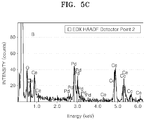
FIGS. 5A through 5C illustrate results of analysis of a catalyst of Example 6 using scanning transmission electron microscopy with energy-dispersive X-ray spectrometry (STEM-EDX); -
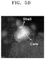
FIG. 5D is a transmission electron microscopic (TEM) image of the catalyst of Example 6; -
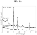
FIGS. 6A and6B illustrate results of X-ray diffraction (XRD) analysis on the catalyst of Example 6 and a catalyst of Comparative Example R6; -
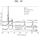
FIG. 6C illustrates results of XRD analysis on catalysts of Examples 11 and 12 and Comparative Example 3; -
FIG. 7A illustrates a result of analysis of the catalyst of Example 6 using X-ray photoelectron spectroscopy (XPS); -
FIG. 7B illustrates results of XRD analysis on catalysts of Example 13 and Comparative Example 6; -
FIG. 7C illustrates a result of extended X-ray absorption fine structure (EXAFS) analysis of the catalyst of Example 13; -
FIG. 8 illustrates a result of oxygen reduction reaction (ORR) activity measurements of half cells including electrodes manufactured according to Manufacture Example 1 and Comparative Manufacture Example 3, which were conducted at room temperature in a 1M HClO4 solution saturated with oxygen; -
FIG. 9 illustrates a result of ORR activity measurements of half cells including electrodes manufactured according to Manufacture Example 2 and Comparative Manufacture Example 1, which were conducted at room temperature in a 1M HClO4 solution saturated with oxygen; -
FIG. 10 illustrates a result of ORR activity measurements of half cells including electrodes manufactured according to Manufacture Examples 3-6 and Comparative Manufacture Example 2, which were conducted at room temperature in a 1M HClO4 solution saturated with oxygen; -
FIG. 11 illustrates a result of ORR activity measurements of half cells including electrodes manufactured according to Manufacture Examples 7-9 and Comparative Manufacture Example 2, which were conducted at room temperature in a 1M HClO4 solution saturated with oxygen; -
FIG. 12 is a graph showing ORR activities at room temperature of half cells including electrodes manufactured according to Manufacture Example 10 and Comparative Manufacture Examples 4-5; and -
FIG. 13 is a graph of cell voltages with respect to current density of fuel cells including catalysts prepared in Example 1 and Comparative Example 1. - Reference will now be made in detail to embodiments, examples of which are illustrated in the accompanying drawings, wherein like reference numerals refer to the like elements throughout. In this regard, the present embodiments may have different forms and should not be construed as being limited to the descriptions set forth herein. Accordingly, the embodiments are merely described below, by referring to the figures, to explain aspects of the present description. As used herein, the term "and/or" includes any and all combinations of one or more of the associated listed items. Expressions such as "at least one of," when preceding a list of elements, modify the entire list of elements and do not modify the individual elements of the list.
- According to an embodiment of the present disclosure, there is provided a catalyst including core-shell structured active particles that have a core including a first metal oxide, and a shell including an alloy of a second metal with a reduction product of the first metal oxide; and wherein the catalyst is: a catalyst including titanium (Ti) as the first metal, and platinum (Pt) as the second metal; a catalyst including titanium (Ti) or cerium (Ce) as the first metal, and a Pdlr alloy as the second metal; or a catalyst including titanium (Ti), cerium (Ce), tantalum (Ta), molybdenum (Mo), tin (Sn), tungsten (W), indium (In), or manganese (Mn) as the first metal; and palladium (Pd) as the second metal.
- The catalyst may further include a carbonaceous support, in addition to active particles with a core-shell structure. The carbonaceous support is reacted to the first metal oxide to prepare a first metal oxide-carbon composite material.
- In an embodiment, when the first metal oxide is supported by the carbonaceous support, and a second metal is added thereto, via high-temperature surface reduction reaction of the first metal oxide in the presence of the second metal, strong bonds are formed between a reduction product of the first metal oxide and the second metal, thereby enhancing activity of the catalyst.
- The amount of the second metal in the catalyst may be from about 1 part to 70 parts by weight based on 100 parts by weight of a total weight of the first metal oxide and a reduction product of the first metal oxide.
-
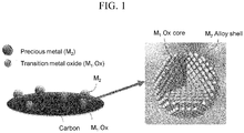
FIG. 1 illustrates a catalyst supported on a carbonaceous support, according to an embodiment of the present disclosure. - Referring to
FIG. 1 , the catalyst includes the active particles with the core-shell structure supported on the carbonaceous support. - Although not illustrated in
FIG. 1 , the catalyst may further include a second metal layer that contains a second metal on an outer surface of the shell. - The core-shell structure of the catalyst may be identified using scanning transmission electron microscopy with energy-dispersive X-ray spectrometry (STEM-EDX).
- The second metal layer may have any thickness that is not specifically limited, for example, may have a thickness of from about 0.1 nm to about 5 nm.
-
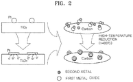
FIG. 2 is a diagram for describing preparation processes of a catalyst, according to an embodiment of the present disclosure, which uses titanium oxide (TiO2) as the first metal oxide, platinum (Pt) as the second metal, and carbon as a carbonaceous support. - As illustrated in
FIG. 2 , when a TiO2/Pt catalyst is subjected to high-temperature reduction at about 400°C or higher, strong chemical bonds are formed between TiO2 and Pt in the catalyst so that Pt spreads over a surface of TiO2. At the same time, a partially reduced titanium oxide Ti4O7 donates electrons to Pt, so that an oxygen reduction reaction (ORR) activity of Pt is enhanced. - According to an embodiment of the present disclosure, a catalyst with a core-shell structure may be obtained by preparing a first metal oxide for forming the core, supporting precious particles or a second metal precursor on the first metal oxide-carbon composite material, and performing a high-temperature reducing process to induce strong metal-support interactions.
- "Strong metal-support interactions" means very strong interactions exerted between the second metal and first metal oxide, which are attributed to chemical bonds between the second metal and first metal oxide formed as a result of reducing a first metal oxide support with the second metal supported thereon.
- The strong bond between a reduction product of the first metal oxide and the second metal may improve activity of the catalyst. Using an electrode including this catalyst, a battery with improved durability and cell performance may be manufactured.
- In an embodiment the catalyst may include titanium (Ti) as the first metal, and platinum (Pt) as the second metal.
- In some embodiments the active particles of the catalyst may include Ti or Ce as the first metal, and an alloy of PdIr such as Pd5Ir as the second metal.
- In some other embodiments the active particles of the catalyst may include Ti, Ce, Ta, Mo, Sn, W, In, or Mn as the first metal, and Pd as the second metal.
- Non-limiting examples of the active particles of the catalyst are active particles with a core including titanium oxide (TiO2) and a shell including an alloy of Pd5Ir with a reduction product (TiO2-y, 0<y≤2) of the titanium oxide; active particles with a core including cerium oxide (CeO2) and a shell including an alloy of Pd5Ir with a reduction product (CeO2-y, 0<y≤2) of the cerium oxide; active particles with a core including tantalum oxide (TaO2.5) and a shell including an alloy of Pd with a reduction product (TaO2.5-y, 0<y≤2.5) of the tantalum oxide; active particles with a core including molybdenum oxide (MoO3) and a shell including an alloy of Pd with a reduction product (MoO3-y, 0<y≤3) of the molybdenum oxide; active particles with a core including tin oxide (SnO2) and a shell including an alloy of Pd with a reduction product (SnO2-y, 0<y≤2) of the tin oxide; active particles with a core including cerium oxide (CeO2) and a shell including an alloy of Pd with a reduction product (CeO2-y, 0<y≤2) of the cerium oxide; active particles with a core including titanium oxide (TiO2) and a shell including an alloy of Pd with a reduction product (TiO2-y, 0<y≤2) of the titanium oxide; active particles with a core including tungsten oxide (WO2) and a shell including an alloy of Pd with a reduction product (WO2-y, 0<y≤2) of the tungsten oxide; active particles with a core including indium oxide (InO1.5) and a shell including an alloy of Pd with a reduction product (InO1.5-y, 0<y≤1.5) of the indium oxide; active particles with a core including titanium oxide (TiO2) and a shell including an alloy of Pt with a reduction product (TiO2-y, 0<y≤2) of the titanium oxide; and active particles with a core including manganese oxide (MnO2), and a shell including an alloy of Pd with a reduction product of the manganese oxide (MnO2-y, 0<y≤2).
- The amount of the second metal (for example, Pd5Ir) in the catalyst may be from about 1 part to 70 parts by weight based on 100 parts by weight of a total weight of a first metal oxide (for example, TiO2) and a reduction product of the first metal oxide (for example, TiO2-y, 0<y≤2). In some embodiments catalysts that are not particularly indicated above may have the same composition as above. The catalyst may further include a carbonaceous support. When the catalyst further includes a carbonaceous support, the carbonaceous support may react with the first metal oxide, such as titanium oxide, cerium oxide, or the like, thereby forming a composite material. As a result, the catalyst may have a core that includes the first metal oxide (titanium oxide)-carbonaceous support composite material, and a shell that includes an alloy of the second metal with a reduction product of the composite material.
- The carbonaceous support may be selected from the group consisting of, for example, ketjen black, carbon black, graphite carbon, carbon nanotubes, Vulcan carbon, and carbon fiber.
- The amount of the carbonaceous support may be from about 10 parts to about 99.9 parts by weight, for example, from about 30 parts to about 80 parts by weight, based on 100 parts by weight of a total weight of the catalyst. When the amount of the carbonaceous support is within these ranges, the catalyst may have improved activity. The total weight of the catalyst means the total weight of the active particles and carbonaceous support.
- The catalyst may be used in an electrode for fuel cells.
- According to another embodiment of the present disclosure, there is provided a fuel cell including a polymer electrolyte membrane, and an anode and a cathode), at least one of the cathode and anode having a catalyst layer that contains the above-described catalyst, on opposite sides of the polymer electrolyte membrane.
- Hydrogen oxidation reaction (HOR) represented below occurs in the anode.
H2 → 2H+ + 2e-
- Hydrogen ions (H+) generated through the reaction diffuse.
- On the other hand, oxygen reduction reaction (ORR) represented below takes place in the cathode.
2H+ + 2e-+ 1/2O2 → H2O
- In the catalyst for electrodes of fuel cells the active particles supported on the carbonaceous support may have a diameter of from about 1 nm to about 20 nm. When the diameter of the active particles is within these ranges, the catalyst may have increased activity. The diameter of the catalyst active particles may be identified using X-ray diffraction (XRD) analysis.
- In an embodiment the catalyst may have high ORR activity.
- Hereinafter, a method of preparing the above-described catalyst, according to an embodiment of the present disclosure, will now be described in detail.
- First, a first metal oxide is mixed with a second metal precursor or second metal particles to obtain a mixture. The mixture is thermally treated at about 400°C or higher to be reduced, thereby preparing the catalyst. These processes will now be described in more detail below.
- Preparation of the first metal oxide particles may involve mixing a first metal precursor and a solvent to obtain a mixture, and drying and thermally treating the mixture to oxidize it. In mixing the first metal precursor and the solvent together, a carbonaceous support may be further added. When the carbonaceous support is further added, as a result of the thermal treatment to induce oxidation, an amorphous or low-crystalline first metal oxide-carbonaceous support composite material may be obtained.
- The solvent may be water, ethanol, methanol, ethylene glycol, or the like.
- The amount of the solvent may be from about 100 parts to about 5000 parts by weight based on 100 parts by weight of the first metal precursor. When the amount of the solvent is within this range, all the components for forming the catalyst may be uniformly and thoroughly dispersed and mixed in the composition.
- Non-limiting examples of the first metal precursor are a nitrate, chloride, sulfide, acetate, acetylacetonate, cyanide, isopropoxide, and butoxide of the first metal.
- The amount of the carbonaceous support may be from about 1 part to about 1,000 parts by weight based on 100 parts by weight of the first metal precursor. When the amount of the carbonaceous support is within this range, the catalyst may have increased activity.
- The mixture of the first metal precursor and the solvent is dried and thermally treated to oxidize it.
- The thermal treatment to induce oxidation may be performed at a temperature of lower then about 300°C, and in some embodiments, may be performed at a temperature from about 100°C to about 299°C. When the thermal treatment to induce oxidation is performed within these temperature ranges, amorphous or low-crystalline first metal oxide or first metal oxide-carbonaceous support composite material particles may be obtained. Using the first metal oxide or first metal oxide-carbonaceous support composite material, the catalyst may have enhanced activity.
- The mixing of the first metal oxide with the second metal precursor or second metal particles together may be performed, for example, in the presence of a reducing agent to disperse the second metal precursor or second metal particles in the first metal oxide. In some embodiments, the second metal particles or may be dispersed in the resulting product obtained by the thermal treatment to induce oxidation using liquid-phase reduction, or the second metal precursor may be dispersed in the resulting product obtained by the thermal treatment to induce oxidation.
- The second metal precursor may be at least one selected from among a palladium precursor and a platinum precursor.
- Non-limiting examples of the palladium and platinum precursor are nitrates, chlorides, sulfides, acetates, acetylacetonates, cyanides, isopropoxides, and butoxides of palladium, platinum, ruthenium, iridium, silver, and gold, respectively.
- The amount of the second metal precursor may be from about 50 parts to about 1000 parts by weight based on 100 parts by weight of the first metal precursor. When the amount of the second metal precursor is within this range, the catalyst may exhibit improved activity.
- The liquid-phase reduction may use a reducing agent, for example, NaBH4, hydrazine, citric acid, hydrogen, or ascorbic acid.
- The amount of the reducing agent may be from about 1 mole to about 5 moles based on 1 mole of the second metal precursor or second metal particles. When the amount of the reducing agent is within this range, reactivity of the reduction reaction may be high.
- The resulting dispersion may be thermally treated at about 400°C or higher to be reduced.
- The thermal treatment to induce reduction may be performed at a temperature of from about 400°C to about 900°C, and in some embodiments, may be performed at a temperature from about 400°C to about 800°C, and in some other embodiments, may be performed at a temperature from about 400°C to about 700°C. When the thermal treatment temperature for reduction is within these ranges, a catalyst with increased activity may be attained.
- The thermal treatment to induce reduction is not specifically limited; for example, the thermal treatment to induce reduction may be performed in a furnace supplied with a reducing gas. The reducing gas may be, for example, a hydrogen gas.
- According to an embodiment of the present disclosure, there is provided a fuel cell including a cathode, an anode, and an electrolyte membrane disposed between the cathode and the anode, wherein at least one of the cathode and the anode contains the above-described catalyst.
- The catalyst may be a catalyst supported on a carbonaceous support, or may be a non-supported catalyst.
- The catalyst may be, for example, a supported catalyst, which may be used in the cathode.
- The fuel cell may be implemented as, for example, a phosphoric acid fuel cell (PAFC), a polymer electrolyte membrane fuel cell (PEMFC), or a direct methanol fuel cell (DMFC).
- In an embodiment the fuel cell may be a PEMFC for vehicles.
-
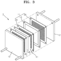
FIG. 3 is a perspective exploded view of afuel cell 1 according to an embodiment of the present disclosure.FIG. 4 is a cross-sectional diagram of a membrane-electrode assembly (MEA) of thefuel cell 1 ofFIG. 3 . - Referring to
FIG. 3 , thefuel cell 1 includes twounit cells 11 that are supported by a pair ofholders 12. Eachunit cell 11 includes anMEA 10, andbipolar plates MEA 10. Thebipolar plates 20 include a conductive metal, carbon or the like, and function as current collectors while providing oxygen and fuel to the catalyst layers of the MEAs10. - Although only two
unit cells 11 are shown inFIG. 3 , the number of unit cells is not limited to two and a fuel cell may have several tens or hundreds of unit cells, depending on the required properties of the fuel cell. - Referring to
FIG. 4 , eachMEA 10 includes anelectrolyte membrane 100, catalyst layers 110 and 110' including an electrode catalyst according to one of the above-described embodiments and respectively disposed on either side of theelectrolyte membrane 100 in the thickness direction thereof; first gas diffusion layers 121 and 121' respectively stacked on the catalyst layers 110 and 110'; and second gas diffusion layers 120 and 120' respectively stacked on the first gas diffusion layers 121 and 121'. - The catalyst layers 110 and 110' include a catalyst according to one of the above-described embodiment, and a binder therein. The catalyst layers 110 and 110' may further include a material able to increase the electrochemical surface area of the catalyst.
- The first gas diffusion layers 121 and 121' and the second gas diffusion layers 120 and 120' may each be formed of a material such as, for example, carbon sheet or carbon paper. The first gas diffusion layers 121 and 121' and the second gas diffusion layers 120 and 120' diffuse oxygen and fuel supplied through the
bipolar plates 20 into the entire surfaces of the catalyst layers 110 and 110'. - The
fuel cell 1 including theMEA 10 operates at a temperature of 100 to 300°C. Fuel such as hydrogen is supplied through one of thebipolar plates 20 into a first catalyst layer, and an oxidant such as oxygen is supplied through the otherbipolar plate 20 into a second catalyst layer. Then, hydrogen is oxidized into protons in the first catalyst layer, and the protons are conducted to the second catalyst layer through theelectrolyte membrane 4. Then, the protons electrochemically react with oxygen in the second catalyst layer to produce water and generate electrical energy. Hydrogen produced by reforming hydrocarbons or alcohols may be used as the fuel. Oxygen as the oxidant may be supplied in the form of air. - According to embodiments of the present disclosure, there are provided an electrode for a lithium air battery that includes core-shell structured active particles having a core that includes a first metal oxide, and a shell that includes an alloy of a second metal with a reduction product of the first metal oxide; and a lithium air battery including the electrode.
- The electrode includes a carbonaceous material. The carbonaceous material may be selected from the group consisting of, for example, ketjen black, carbon black, graphite carbon, carbon nanotubes, Vulcan carbon, and carbon fiber.
- The active particles may be used as an electrode active material. The electrode active material may be, for example, a cathode active material.
- Types and amounts of the first metal and second metal in the active particles may be identical to those used in the catalyst described above.
- Hereinafter, one or more embodiments of the present invention will be described in detail with reference to the following examples. These examples are not intended to limit the purpose and scope of the one or more embodiments of the present invention.
- 0.78 g of titanium tetraisopropoxide (Ti(OCH(CH3)2)4) as a titanium precursor and 1 g of Ketjen Black (KB) as a carbonaceous material were dispersed in 100 g of ethanol and mixed together to prepare a mixed solution.
- The mixed solution was dried by distillation at about 60°C under a reduced pressure, and heated at about 200°C in the air to prepare an amorphous titanium oxide-carbon composite material.
- Afterward, 0.914 g of palladium nitrate (Pd(NO3)2·2H2O) as a Pd precursor and 0.340 g of hexachloroiridic acid hexahydrate as an Ir precursor were dissolved in distilled water to prepare a mixed solution. 0.5 g of the titanium oxide-carbon composite material was added to 300 g of this mixed solution, followed by titration with a 10 wt% NaOH solution to
pH 11, and agitation. - 1 g of NaBH4 dissolved in 100 g of distilled water was added to the titrated mixed solution that was agitated so that Pd5Ir particles were dispersed on the titanium oxide-carbon composite material. The resulting mixture was thermally treated at about 500°C in a hydrogen atmosphere to obtain a catalyst including active materials supported on the carbonaceous support, wherein the active materials had a core of titanium oxide (TiO2) and a shell of an alloy of Pd5Ir with a reduction product (TiO2-y, 0<y≤2) of the titanium oxide. The amount of the carbonaceous support was about 40 parts by weight based on 100 parts by weight of a total weight of the catalyst.
- 0.99 g of CeCl3·7H2O as a Ce precursor and 1 g of KB as a carbonaceous material were dispersed in 100 g of distilled water and mixed together to prepare a mixed solution.
- The mixed solution was dried by distillation at about 60°C under a reduced pressure, and heated at about 200°C in the air to prepare a cerium oxide-carbon composite material in the form of nanoparticulates.
- Afterward, the same catalyst preparation processes as used in Example 1, in which Pd and Ir were supported on the titanium oxide-carbon composite material, were performed except that the cerium oxide-carbon composite material instead of the titanium oxide-carbon composite material was used, thereby preparing a catalyst including active particles supported on the carbonaceous support, wherein the active particles had a core of cerium oxide (CeO2) and a shell of an alloy of Pd5Ir with a reduction product (CeO2-y, 0<y≤2) of the cerium oxide. The amount of the carbonaceous support was about 40 parts by weight based on 100 parts by weight of a total weight of the catalyst.
- 0.952 g of tantalum chloride as a Ta precursor and 1 g of KB as a carbonaceous material were dispersed in 100 g of distilled water to prepare a mixed solution.
- The mixed solution was dried by distillation at about 60°C under a reduced pressure, and heated at about 200°C in the air to prepare a tantalum oxide-carbon composite material in the form of nanoparticulates.
- Afterward, 1.24g of palladium nitrate (Pd(NO3)2·2H2O) as a Pd precursor was dissolved in distilled water to prepare a mixed solution. 0.5 g of the tantalum oxide-carbon composite material was added to 60 g of this mixed solution and agitated.
- The mixed solution was dried by distillation at about 60°C under a reduced pressure. Subsequently, the dried product was thermally treated at about 500°C in a hydrogen atmosphere, thereby preparing a catalyst including active particles supported on the carbonaceous support, wherein the active particles had a core of tantalum oxide (TaO2.5) and a shell of an alloy of Pd with a reduction product (TaO2.5-y, 0<y≤2.5) of the tantalum oxide. The amount of the carbonaceous support was about 40 parts by weight based on 100 parts by weight of a total weight of the catalyst.
- 0.47 g of ammonium molybdate tetrahydrate as a Mo precursor and 1 g of KB as a carbonaceous material were dispersed in 100 g of distilled water to prepare a mixed solution.
- The mixed solution was dried by distillation at about 60°C under a reduced pressure, and heated at about 200°C in the air to prepare a molybdenum oxide-carbon composite material in the form of nanoparticulates.
- Afterward, 1.24 g of palladium nitrate (Pd(NO3)·2H2O) as a Pd precursor was dissolved in distilled water to prepare a mixed solution. 0.5 g of the molybdenum oxide-carbon composite material was added to 60 g of this mixed solution and agitated. The mixed solution was dried by distillation at about 60°C under a reduced pressure.
- Subsequently, the dried product was thermally treated at about 500°C in a hydrogen atmosphere, thereby preparing a catalyst including active particles supported on the carbonaceous support, wherein the active particles had a core of molybdenum oxide (MoO3) and a shell of an alloy of Pd with a reduction product (MoO3-y, 0<y≤3) of the molybdenum oxide. The amount of the carbonaceous support was about 40 parts by weight based on 100 parts by weight of a total weight of the catalyst.
- 0.5 g of tin chloride (SnCl2) as a Sn precursor and 1 g of KB as a carbonaceous material were dispersed in 100 g of distilled water to prepare a mixed solution.
- The mixed solution was dried by distillation at about 60°C under a reduced pressure, and heated at about 200°C in the air to prepare a tin oxide-carbon composite material in the form of nanoparticulates.
- Afterward, 1.24 g of palladium nitrate (Pd(NO3)·2H2O) as a Pd precursor was dissolved in distilled water to prepare a mixed solution. 0.5 g of the tin oxide-carbon composite material was added to 60 g of this mixed solution and agitated. The mixed solution was dried by distillation at about 60°C under a reduced pressure. Subsequently, the dried product was thermally treated at about 500°C in a hydrogen atmosphere, thereby preparing a catalyst including active particles supported on the carbonaceous support, wherein the active particles had a core of tin oxide (SnO2) and a shell of an alloy of Pd with a reduction product (SnO2-y, 0<y≤2) of the tin oxide. The amount of the carbonaceous support was about 40 parts by weight based on 100 parts by weight of a total weight of the catalyst.
- 1.24 g of palladium nitrate (Pd(NO3)·2H2O) as a Pd precursor was dissolved in distilled water to prepare a mixed solution. 0.5 g of the cerium oxide-carbon composite material of Example 2 was added to 60 g of this mixed solution and agitated. The mixed solution was dried by distillation at about 60°C under a reduced pressure.
- Subsequently, the dried product was thermally treated at about 500°C in a hydrogen atmosphere, thereby preparing a catalyst including active particles supported on the carbonaceous support, wherein the active particles had a core of cerium oxide (CeO2) and a shell of an alloy of Pd with a reduction product (CeO2-y, 0<y≤2) of the cerium oxide. The amount of the carbonaceous support was about 40 parts by weight based on 100 parts by weight of a total weight of the catalyst.
- 1.24 g of palladium nitrate (Pd(NO3)·2H2O) as a Pd precursor was dissolved in distilled water to prepare a mixed solution. 0.5 g of the titanium oxide-carbon composite material of Example 1 was added to 60 g of this mixed solution and agitated. The mixed solution was dried by distillation at about 60°C under a reduced pressure.
- Subsequently, the dried product was thermally treated at about 500°C in a hydrogen atmosphere, thereby preparing a catalyst including active particles supported on the carbonaceous support, wherein the active particles had a core of titanium oxide (TiO2) and a shell of an alloy of Pd with a reduction product (TiO2-y, 0<y≤2) of the titanium oxide. The amount of the carbonaceous support was about 40 parts by weight based on 100 parts by weight of a total weight of the catalyst.
- 0.33 g of ammonium metatungstate ((NH4)6H2W12O40) as a W precursor and 1 g of KB as a carbonaceous material were dispersed in 100 g of distilled water to prepare a mixed solution.
- The mixed solution was dried by distillation at about 60°C under a reduced pressure, and heated at about 200°C in the air to prepare a tungsten oxide-carbon composite material.
- Afterward, 1.24 g of palladium nitrate (Pd(NO3)·2H2O) as a Pd precursor was dissolved in distilled water to prepare a mixed solution. 0.5 g of the tungsten oxide-carbon composite material was added to 60 g of this mixed solution and agitated.
- The mixed solution was dried by distillation at about 60°C under a reduced pressure. Subsequently, the dried product was thermally treated at about 500°C in a hydrogen atmosphere, thereby preparing a catalyst including active particles supported on the carbonaceous support, wherein the active particles had a core of tungsten oxide (WO2) and a shell of an alloy of Pd with a reduction product (WO2-y, 0<y≤2) of the tungsten oxide. The amount of the carbonaceous support was about 40 parts by weight based on 100 parts by weight of a total weight of the catalyst.
- 1 g of indium acetate ((CH3CO2)3In·H2O) as an In precursor and 1 g of KB as a carbonaceous material were dispersed in 100 g of distilled water to prepare a mixed solution.
- The mixed solution was dried by distillation at about 60°C under a reduced pressure, and heated at about 200°C in the air to prepare an indium oxide-carbon composite material.
- Afterward, 1.24 g of palladium nitrate (Pd(NO3)·2H2O) as a Pd precursor was dissolved in distilled water to prepare a mixed solution. 0.5 g of the indium oxide-carbon composite material was added to 60 g of this mixed solution and agitated. The mixed solution was dried by distillation at about 60°C under a reduced pressure. Subsequently, the dried product was thermally treated at about 500°C in a hydrogen atmosphere, thereby preparing a catalyst including active particles supported on the carbonaceous support, wherein the active particles had a core of indium oxide (InO1.5) and a shell of an alloy of Pd with a reduction product (InO1.5-y, 0<y≤1.5) of the indium oxide. The amount of the carbonaceous support was about 40 parts by weight based on 100 parts by weight of a total weight of the catalyst.
- 0.332g of H2PtCl6·6H2O as a Pt precursor was dissolved in distilled water to prepare a mixed solution. 0.5 g of the titanium oxide-carbon composite material of Example 1 was added to 60 g of this mixed solution and agitated.
- The mixed solution was dried by distillation at about 60°C under a reduced pressure.
- Subsequently, the dried product was thermally treated at about 500°C in a hydrogen atmosphere, thereby preparing a catalyst including active particles supported on the carbonaceous support, wherein the active particles had a core of titanium oxide (TiO2) and a shell of an alloy of Pt with a reduction product (TiO2-y, 0<y≤2) of the titanium oxide. The amount of the carbonaceous support was about 40 parts by weight based on 100 parts by weight of a total weight of the catalyst.
- A catalyst including active particles supported on a carbonaceous support wherein the active particles had a core of tin oxide (SnO2) and a shell of an alloy of Pd with a reduction product (SnO2-y, 0<y≤2) of the tin oxide was prepared in the same manner as in Example 5, except that the temperature of the thermal treatment in the hydrogen atmosphere was changed from about 500°C to about 600°C. The amount of the carbonaceous support was about 40 parts by weight based on 100 parts by weight of a total weight of the catalyst.
- A catalyst including active particles supported on a carbonaceous support wherein the active particles had a core of indium oxide (InO1.5) and a shell of an alloy of Pd with a reduction product (InO1.5-y, 0<y≤1.5) of the indium oxide was prepared in the same manner as in Example 9, except that the temperature of the thermal treatment in the hydrogen atmosphere was changed from about 500°C to about 600°C. The amount of the carbonaceous support was about 40 parts by weight based on 100 parts by weight of a total weight of the catalyst.
- 0.384 g of (Mn(NO3)2·2H2O as a Mn precursor and 1 g of KB as a carbonaceous material were dispersed in 100 g of distilled water to prepare a mixed solution.
- The mixed solution was dried by distillation at about 60°C under a reduced pressure, and heated at about 200°C in the air to prepare a manganese oxide-carbon composite material.
- Afterward, 1.24g of palladium nitrate (Pd(NO3)·2H2O) as a Pd precursor was dissolved in distilled water to prepare a mixed solution. 0.5 g of the manganese oxide-carbon composite material was added to 60 g of this mixed solution and agitated.
- The mixed solution was dried by distillation at about 60°C under a reduced pressure. Subsequently, the dried product was thermally treated at about 500°C in a hydrogen atmosphere, thereby preparing a catalyst including active particles supported on the carbonaceous support, wherein the active particles had a core of manganese oxide (MnO2) and a shell of an alloy of Pd with a reduction product (MnO2-y, 0<y≤2) of the manganese oxide. The amount of the carbonaceous support was about 40 parts by weight based on 100 parts by weight of a total weight of the catalyst.
- The same catalyst preparation processes as in Example 1 where Pd and Ir were supported on the titanium oxide-carbon composite material were performed except that 0.5 g of KB as a carbonaceous material was used instead of the titanium oxide-carbon composite material, thereby preparing a Pd5Ir/C catalyst with Pd5Ir particulates dispersed on the carbonaceous material. The amount of the carbonaceous support was about 40 parts by weight based on 100 parts by weight of a total weight of the catalyst.
- 1.24 g of palladium nitrate (Pd(NO3)·2H2O) as a Pd precursor was dissolved in distilled water to prepare a mixed solution. 0.5 g of KB as a carbonaceous material was added to 60 g of this mixed solution and agitated. The amount of the carbonaceous support was about 40 parts by weight based on 100 parts by weight of a total weight of the catalyst.
- The mixed solution was dried by distillation at about 60°C under a reduced pressure. Subsequently, the dried product was thermally treated at about 500°C in a hydrogen atmosphere, thereby preparing a Pd/C catalyst with Pd particulates dispersed on the carbonaceous material.
- A catalyst was prepared in the same manner as in Example 1 except that the thermal treatment in the hydrogen atmosphere was performed at about 300°C. The amount of the carbonaceous support was about 40 parts by weight based on 100 parts by weight of a total weight of the catalyst.
- A catalyst was prepared in the same manner as in Example 6 except that the thermal treatment in the hydrogen atmosphere was performed at about 300°C. The amount of the carbonaceous support was about 40 parts by weight based on 100 parts by weight of a total weight of the catalyst.
- 0.384 g of manganese nitrate (Mn(NO3)·2H2O) as a Mn precursor was dissolved in distilled water to prepare a mixed solution. 0.5 g of KB as a carbonaceous material was added to 60 g of this mixed solution and agitated.
- The mixed solution was dried by distillation at about 60°C under a reduced pressure. Subsequently, the dried product was thermally treated at about 500°C in a hydrogen atmosphere, thereby preparing a MnO2/C catalyst with MnO2 particulates dispersed on the carbonaceous material. The amount of the carbonaceous support was about 40 parts by weight based on 100 parts by weight of a total weight of the catalyst.
- A rotating disk electrode (RDE) was manufactured as follows.
- The catalyst prepared in Example 1 and a Nafion solution (Nafion perfluorinated ion-exchange resin, 5 wt % solution in a mixture of lower aliphatic alcohols and water, available from Aldrich) were mixed and homogenized to prepare a catalyst slurry, which was then coated on glassy carbon to form an electrode in thin film form, thereby completing the manufacture of the RDE.
- Electrodes were manufactured in the same manner as in Manufacture Example 1, except that the catalysts of Examples 2-10, instead of the catalyst of Example 1, were respectively used.
- Electrodes were manufactured in the same manner as in Manufacture Example 1, except that the catalysts of Comparative Examples 1-3, instead of the catalyst of Example 1, were respectively used.
- An electrode was manufactured in the same manner as in Manufacture Example 1, except that a 20wt% Pt/C catalyst (available from E-Tek), instead of the catalyst of Example 1, was used.
- An electrode was manufactured in the same manner as in Manufacture Example 1, except that a 48.5wt% Pt/C catalyst (available from TKK), instead of the catalyst of Example 1, was used.
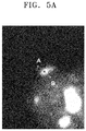
- The catalyst of Example 6 was analyzed using scanning transmission electron microscopy with energy-dispersive X-ray spectrometry (STEM-EDX). The result is shown in
FIGS. 5A through 5C .FIG. 5D is a TEM image of the catalyst of Example 6. InFIG. 5A , A indicates data on a shell region of the catalyst, and B indicates data on a core-shell region of the catalyst. - Referring to
FIGS. 5A through 5C , the catalyst of Example 6 is found to include cerium (Ce) both in the core and shell, but more in the core than in the shell. -
FIG. 5D confirms that the catalyst has a core-shell structure. - X-ray diffraction analysis was performed on the catalyst of Example 6 and the catalyst of Comparative Example 4 using an X-ray diffraction_analyzer (MP-XRD, Xpert PRO, available from Philips / Power 3kW). The results are shown in
FIGS. 6A and6B . - Referring to
FIG. 6A , both the catalysts of Examples 6 and Comparative Example 4 are found to include cerium mostly in the form of crystalline cerium oxide (CeO2). - Referring to
FIG. 6B , the catalyst of Comparative Example 4 after the reducing process at about 300°C is found to have the Pd 111 peak at 40.15°, indicating the presence of pure Pd. The catalyst of Example 6 after the reducing process at about 500°C is found to have the Pd 111 peak shifted to 40.22°, as shown inFIG. 5B . This indicates the presence of an alloy on the core surface by chemical bonds between Pd and a reduction product of cerium oxide on the core surface. - XRD analysis was performed on the catalysts of Examples 11 and 12 and Comparative Example 3. The results are shown in
FIG. 6C . - Referring to
FIG. 6C , the catalyst of Example 11 is found to include an alloy (indicated as a Pd-Me alloy inFIG. 6C ) formed by interaction between Pd and a reduction product of surficial tin oxide particles. The catalyst of Example 12 is found to include an alloy (indicated as Pd-Me alloy inFIG. 6C ) formed by interaction between Pd and a reduction product of surficial indium oxide particles. - XPS analysis was performed using a non-monochromatic Al Ka X-ray at a chamber pressure of about 5x10⁻¹⁰ mbar in a post-excitation state (after excitation using an ESCA 250 spectrometer).
- The catalyst of Example 6 was analyzed for an oxidation state of the cerium oxide on the catalyst surface using X-ray photoelectron spectroscopy (XPS). The result is shown in
FIG. 7A . The XPS analysis was performed with a depth adjustment to about 5 nm from the shell surface of the catalyst to identify the state of Ce over the depth range. - Referring to
FIG. 7A , both a tetravalent Ce (CeO2 in the core) and a reduced trivalent Ce (reduced Ce bound with Pd on the core surface) are clearly found on the core surface of the catalyst. - The catalysts of Example 13 and Comparative Example 5 were analyzed for an oxidation state of the manganese oxide on the catalyst surface using XPS. The results are shown in
FIG. 7B . The XPS analysis was performed with a transmission depth adjustment to about 5 nm. -
FIG. 7B comparatively shows the oxidation state of Mn between the catalyst of Comparative Example 5 and the catalyst of Example 3. - The catalyst of
Comparative 5 exhibits only a peak of Mn (binding energy: about 642eV) with an oxidation number of +4, while the catalyst of Example 13 exhibits a Mn peak (binding energy: about 640.8eV) from MnO resulting from a partial reduction of MnO2, a peak of Mn in a metal state (binding energy: about 639eV), and a peak of Mn with an oxidation number of +4 (binding energy: about 642eV). This also indicates that the catalyst of Example 13 includes a reduced Mn oxide and metal Mn, which resulted from the thermal treatment in a hydrogen reducing atmosphere at about 500°C. - EXAFS analysis was performed on the catalyst of Example 13. The results are shown in
FIG. 7C and Table 1 below.Table 1 Absorption edge Sample Pair R (nm) N σ2 (pm2) Pd K edge Pd/MnOx/C Before reduction Pd-O 0.200 0.6 ∼0 Pd-Pd 0.269 0.9 20 Pd-Mn 0.302 0.8 43 Pd/MnOx/C After reduction Pd-O 0.198 0.5 ∼0 Pd-Pd 0.268 1.5 11 Pd-Mn 0.298 1.5 43 - In Table 1 above, before and after reduction mean before and after the thermal treatment at about 500°C in the hydrogen atmosphere in Example 13, respectively, R represents a bond length and σ2 represents a device factor.
- Referring to
FIG. 7C and Table 1, a Pd-Mn coordination number was increased from 0.8 before reduction to 1.5 after reduction, indicating formation of an alloy of Pd with a reduction product of manganese oxide. - Rotating disk electrodes (RDEs) manufactured in Manufacture Example 1 and Comparative Manufacture Example 3 were used as working electrodes.
- Electrochemical evaluation was performed using a three-electrode system. Each half cell was manufactured using an oxygen-saturated 0.1 M-HClO4 solution as an electrolyte, and a Pt foil and a Ag/AgCI electrode, respectively, as a counter electrode and a reference electrode. All the electrochemical experiments were performed at room temperature.
- In a 0.1M HClO4 electrolyte solution saturated with oxygen, while rotating the RDE of each of the three-electrode cells at 900 rpm with voltage changes at a scan rate of 5 mV/s, current density values were measured at a voltage range from an onset potential (OCV) to about 0.9V as ORR activities at room temperature. The results are shown in
FIG. 8 - An onset potential refers to a voltage level at which current starts to flow due to an ORR. A catalyst activity is determined from a difference between ORR current values at the onset potential and a potential nearest to the onset potential.
- In
FIG. 8 , RHE is an abbreviation for reversible hydrogen electrode. - Referring to
FIG. 8 , the fuel cell of Manufacture Example 1 was found to have improved ORR activities compared with the fuel cell of Comparative Manufacture Example 3. - The ORR activities of the half cells according to Manufacture Example 2, and Comparative Manufacture Examples 1 and 4 were measured at room temperature in a 0.1M HClO4 solution saturated with oxygen. The results are shown in
FIG. 9 . - Referring to
FIG. 9 , the half cell according to Manufacture Example 2 has improved ORR activities compared with the fuel cells according to Comparative Manufacture Examples 1 and 4. - The ORR activities of the half cells according to Manufacture Examples 3-6 and Comparative Manufacture Example 2 were measured at room temperature in a 0.1M HClO4 solution saturated with oxygen. The results are shown in
FIG. 10 . - Referring to
FIG. 10 , the half cells according to Manufacture Examples 3-6 have improved ORR activities compared with the half cell according to Comparative Manufacture Example 2. - The ORR activities of the half cells according to Manufacture Examples 7-9 and Comparative Manufacture Example 2 were measured at room temperature in a 0.1M HClO4 solution saturated with oxygen. The results are shown in
FIG. 11 . - Referring to
FIG. 11 , the half cells according to Manufacture Examples 7-9 have improved ORR activities compared with the half cell according to Comparative Manufacture Example 2. - The ORR activities of the half cells according to Manufacture Example 10 and Comparative Manufacture Examples 4-5 were measured at room temperature in a 0.1M HClO4 solution saturated with oxygen. The results are shown in
FIG. 12 . - Referring to
FIG. 12 , the half cell according to Manufacture Example 10 has better ORR activities than the half cells according to Comparative Manufacture Examples 4-5. - The ORR activities in
FIGS. 9-12 were measured using the same method as described in connection withFIG. 6 . - Fuel cells were manufactured using the catalysts of Example 1 and Comparative Example 1 as follows.
- To manufacture an anode of a PEMFC, 0.03 g of polyvinylidene fluoride (PVDF) and an adequate amount of N-methyl-2-pyrrolidone (NMP) solvent were mixed per 1 g of Pdlr, to prepare an anode-forming slurry. The anode slurry was coated on a microporous layer-coated carbon paper using a bar coater, and the resultant was dried while the temperature was stepwise increased from room temperature to 150°C, thereby producing an anode. The amount of the catalyst loaded in the anode was 1mg/cm2.
- A cathode was manufactured using the catalyst of Example 1 in the same manner as in the manufacture of the anode described above. The amount of the catalyst loaded in the cathode was about1.5 mg/cm2.
- A PEMFC was manufactured by disposing poly(2,5-benzimidazole) doped with 85 wt% phosphoric acid as an electrolyte membrane between the anode and the cathode. The fuel cell manufactured using the catalyst of Comparative Example 1 was manufactured in the same manner as in the fuel cell manufactured using the catalyst of Example 1 except that the catalyst of Comparative Example 1 was used for forming teh cathode.
- Cell voltages with respect to current density were measured using the fuel cells including the catalysts of Example 1 and Comparative Example 1. The results are shown in
FIG. 13 . - Referring to
FIG. 13 , the fuel cell using the catalyst of Example 1 is found to have improved cell performed as compared with the fuel cell using the catalyst of Comparative Example 1. - As described above, according to the one or more of the above embodiments of the present disclosure, a catalyst has enhanced oxygen-reduction activity. Therefore, using the catalyst, a fuel cell with higher ORR activities may be manufactured.
- It should be understood that the exemplary embodiments described therein should be considered in a descriptive sense only and not for purposes of limitation. Descriptions of features or aspects within each embodiment should typically be considered as available for other similar features or aspects in other embodiments.
Claims (11)
- A catalyst comprising active particles that have:a core comprising a first metal oxide; anda shell comprising an alloy of a second metal with a reduction product of the first metal oxide; andwherein the catalyst is:a catalyst including titanium (Ti) as the first metal, and platinum (Pt) as the second metal;a catalyst including titanium (Ti) or cerium (Ce) as the first metal, and a Pdlr alloy as the second metal; ora catalyst including titanium (Ti), cerium (Ce), tantalum (Ta), molybdenum (Mo), tin (Sn), tungsten (W), indium (In), or manganese (Mn) as the first metal; and palladium (Pd) as the second metal.
- The catalyst of claim 1, wherein the active particles further comprise a second metal layer including the second metal on an outer surface of the shell.
- The catalyst of claim 1 or 2, wherein the catalyst comprises:active particles with a core including titanium oxide (TiO2), and a shell including an alloy of Pd5Ir with a reduction product (TiO2-y, 0<y≤2) of the titanium oxide;active particles with a core including cerium oxide (CeO2), and a shell including an alloy of Pd5Ir with a reduction product (CeO2-y, 0<y≤2) of the cerium oxide;active particles with a core including tantalum oxide (TaO2.5), and a shell including an alloy of Pd with a reduction product (TaO2.5-y, 0<y≤2.5) of the tantalum oxide;active particles with a core including molybdenum oxide (MoO3), and a shell including an alloy of Pd with a reduction product (MoO3-y, 0<y≤3) of the molybdenum oxide;active particles with a core including tin oxide (SnO2), and a shell including an alloy of Pd with a reduction product (SnO2-y, 0<y≤2) of the tin oxide;active particles with a core including cerium oxide (CeO2), and a shell including an alloy of Pd with a reduction product (CeO2-y, 0<y≤2) of the cerium oxide;active particles with a core including titanium oxide (TiO2), and a shell including an alloy of Pd with a reduction product (TiO2-y, 0<y≤2) of the titanium oxide;active particles with a core including tungsten oxide (WO2), and a shell including an alloy of Pd with a reduction product (WO2-y, 0<y≤2) of the tungsten oxide;active particles with a core including indium oxide (InO1.5), and a shell including an alloy of Pd with a reduction product (InO1.5-y, 0<y≤1.5) of the indium oxide;active particles with a core including titanium oxide (TiO2), and a shell including an alloy of Pt with a reduction product (TiO2-y, 0<y≤2) of the titanium oxide; oractive particles with a core including manganese oxide (MnO2), and a shell including an alloy of Pd with a reduction product (MnO2-y, 0<y≤2) of the manganese oxide.
- The catalyst of any of claims 1-3, further comprising a carbonaceous support on which the active particles are supported.
- A method of preparing the catalyst of any one of claims 1-4, the method comprising:mixing a first metal oxide and a second metal precursor or second metal particles together to obtain a mixture; andperforming thermal treatment to induce reduction on the mixture at 400°C or higher, preferably in the range of 400-900°C.
- The method of claim 5, wherein the first metal oxide is prepared by:mixing a first metal precursor and a solvent together to obtain a mixture; anddrying the mixture and performing thermal treatment to induce oxidation on the mixture.
- The method of claim 5, wherein the mixing of the first metal oxide and the metal precursor or second metal particles together is performed in the presence of a reducing agent so that the second metal precursor or second metal particles is dispersed in the first metal oxide.
- A fuel cell comprising a cathode, an anode, and an electrolyte membrane disposed between the cathode and the anode, wherein at least one of the cathode and anode comprises the catalyst of any one of claims 1 to 4.
- An electrode for a lithium air battery, the electrode comprising:active particles with a core that includes a first metal oxide, anda shell that includes an alloy of a second metal with a reduction product of the firs metal oxide; andwherein the active particle is an active particle including titanium (Ti) as the first metal, and platinum (Pt) as the second metal;an acitve particle including titanium (Ti) or cerium (Ce) as the first metal, and a Pdlr alloy as the second metal; oran acitve particle including titanium (Ti), cerium (Ce), tantalum (Ta), molybdenum (Mo), tin (Sn), tungsten (W), indium (In), or manganese (Mn) as the first metal; and palladium (Pd) as the second metal.
- The electrode for a lithium air battery of claim 9, further comprising a carbonaceous support.
- A lithium air battery comprising the electrode of claim 9 or 10.
Applications Claiming Priority (1)
| Application Number | Priority Date | Filing Date | Title |
|---|---|---|---|
| KR20110003551 | 2011-01-13 |
Publications (3)
| Publication Number | Publication Date |
|---|---|
| EP2477264A2 EP2477264A2 (en) | 2012-07-18 |
| EP2477264A3 EP2477264A3 (en) | 2014-04-30 |
| EP2477264B1 true EP2477264B1 (en) | 2018-12-19 |
Family
ID=45509275
Family Applications (1)
| Application Number | Title | Priority Date | Filing Date |
|---|---|---|---|
| EP12150833.7A Active EP2477264B1 (en) | 2011-01-13 | 2012-01-11 | Catalyst including active particles, method of preparing the catalyst, fuel cell including the catalyst, electrode including the active particles for lithium air battery, and lithium air battery including the electrode |
Country Status (5)
| Country | Link |
|---|---|
| US (1) | US9123976B2 (en) |
| EP (1) | EP2477264B1 (en) |
| JP (1) | JP5907736B2 (en) |
| KR (1) | KR101819038B1 (en) |
| CN (1) | CN102593472B (en) |
Families Citing this family (47)
| Publication number | Priority date | Publication date | Assignee | Title |
|---|---|---|---|---|
| KR102007412B1 (en) * | 2011-09-27 | 2019-08-05 | 삼성에스디아이 주식회사 | Electrode catalyst for fuel cell, method for preparing the same, membrane electrode assembly and fuel cell including the same |
| KR20130087292A (en) * | 2012-01-27 | 2013-08-06 | 삼성전자주식회사 | Composite, catalyst including the composite, fuel cell including the same, and lithium air battery including the same |
| KR101454877B1 (en) * | 2012-11-06 | 2014-11-04 | 한국과학기술원 | Bifunctional catalysts using bimetallic material for cathode of Li-air battery |
| KR101481230B1 (en) * | 2012-11-14 | 2015-01-12 | 인하대학교 산학협력단 | Positive Electrode for Lithium Air Battery, Method of Preparing the Same, and Lithium Air Battery Employing the Same |
| US9178219B2 (en) | 2012-12-20 | 2015-11-03 | Ford Global Technologies, Llc | Electrochemical device including amorphous metal oxide |
| CN103084175B (en) * | 2013-01-31 | 2015-04-15 | 武汉大学 | Pt-Au@Pt core-shell structure fuel cell cathode catalyst and preparation method thereof |
| JP6172734B2 (en) * | 2013-03-04 | 2017-08-02 | 国立大学法人電気通信大学 | Catalyst for polymer electrolyte fuel cell cathode and method for producing such catalyst |
| KR102056527B1 (en) * | 2013-05-10 | 2019-12-16 | 니뽄 고아 가부시끼가이샤 | Fuel cell electrode catalyst and method for activating catalyst |
| CN104600319B (en) * | 2013-10-31 | 2018-06-22 | 中国科学院上海硅酸盐研究所 | Non-carbon lithium-air electrode |
| CN104934615A (en) * | 2014-03-21 | 2015-09-23 | 中国科学院大连化学物理研究所 | Application of tin-containing nanometer oxide to cathode of low-temperature solid oxide fuel cell |
| JP6570515B2 (en) * | 2014-03-25 | 2019-09-04 | 国立大学法人横浜国立大学 | Oxygen reduction catalyst and method for producing the same |
| CN103915612A (en) * | 2014-04-18 | 2014-07-09 | 云南大学 | High-capacity MoO3-SnO2@C composite lithium ion battery core-shell negative material and preparation method |
| US9468909B2 (en) | 2014-06-27 | 2016-10-18 | Ford Global Technologies, Llc | Metal oxide stabilized platinum-based ORR catalyst |
| EP3171436A4 (en) * | 2014-07-18 | 2017-12-27 | IUCF-HYU (Industry-University Cooperation Foundation Hanyang University) | Lithium air battery and method for manufacturing same |
| US9929453B2 (en) | 2014-08-04 | 2018-03-27 | Uchicago Argonne, Llc | Bi-metallic nanoparticles as cathode electrocatalysts |
| KR101786408B1 (en) * | 2014-08-28 | 2017-10-17 | 엔.이. 켐캣 가부시키가이샤 | Catalyst for electrode, composition for forming gas diffusion electrode, gas diffusion electrode, membrane electrode assembly, and fuel cell stack |
| EP2999032B1 (en) * | 2014-09-18 | 2017-08-09 | Kabushiki Kaisha Toshiba | Active material, nonaqueous electrolyte battery, and battery pack |
| KR101670929B1 (en) * | 2014-10-21 | 2016-11-07 | 서울대학교산학협력단 | Catalytic materials and electrodes for oxygen evolution, and systems for electrochemical reaction |
| US11332834B2 (en) | 2014-10-21 | 2022-05-17 | Seoul National University R&Db Foundation | Catalyst and manufacturing method thereof |
| WO2016084762A1 (en) * | 2014-11-28 | 2016-06-02 | 昭和電工株式会社 | Catalyst carrier and method for manufacturing same |
| KR101602416B1 (en) * | 2014-12-12 | 2016-03-11 | 한국에너지기술연구원 | Cathode for Lithium-Air Battery, Method of Manufacturing the Same, and Lithium-Air Battery Comprising the Same |
| WO2016102440A1 (en) * | 2014-12-22 | 2016-06-30 | Basf Se | Carbon supported catalyst comprising a modifier and process for preparing the carbon supported catalyst |
| US9871256B2 (en) | 2015-02-04 | 2018-01-16 | Nissan North America, Inc. | Fuel cell electrode having non-ionomer proton-conducting material |
| JP6433319B2 (en) * | 2015-02-04 | 2018-12-05 | 新日鐵住金株式会社 | METAL CATALYST PARTICLE FOR SOLID POLYMER FUEL CELL, PROCESS FOR PRODUCING THE SAME, CATALYST AND SOLID POLYMER FUEL CELL |
| US9698428B2 (en) | 2015-02-04 | 2017-07-04 | Nissan North America, Inc. | Catalyst support particle structures |
| US20180048042A1 (en) * | 2015-02-26 | 2018-02-15 | Massachusetts Institute Of Technology | Rechargeable electrochemical system using transition metal promoter |
| US10177395B2 (en) * | 2015-03-31 | 2019-01-08 | N.E. Chemcat Corporation | Electrode catalyst, composition for forming gas diffusion electrode, gas diffusion electrode, membrane-electrode assembly, fuel cell stack, method for producing electrode catalyst, and composite particle |
| FR3041163A1 (en) * | 2015-09-11 | 2017-03-17 | Centre Nat Rech Scient | TYPE P / METAL-N-C HYBRID CATALYST |
| CN105304975A (en) * | 2015-11-27 | 2016-02-03 | 上海空间电源研究所 | Air electrode material of lithium-air battery and preparation method of air electrode material |
| US9822053B2 (en) * | 2016-01-28 | 2017-11-21 | Eastman Chemical Company | Single step conversion of N-butyraldehyde to 2-ethylhexanal |
| CN105762377A (en) * | 2016-02-22 | 2016-07-13 | 扬州大学 | Palladium-iron (Pd-Fe) bimetallic electro-catalysis material and preparation method thereof |
| WO2017150009A1 (en) * | 2016-02-29 | 2017-09-08 | エヌ・イー ケムキャット株式会社 | Catalyst for electrode, composition for forming gas diffusion electrode, gas diffusion electrode, membrane electrode assembly, and fuel cell stack |
| EP3425712A1 (en) | 2016-02-29 | 2019-01-09 | N.E. Chemcat Corporation | Catalyst for electrode, composition for forming gas diffusion electrode, gas diffusion electrode, membrane electrode assembly, and fuel cell stack |
| TWI592213B (en) * | 2016-03-16 | 2017-07-21 | 國立清華大學 | Catalyst layer and manufacturing method thereof, membrane electrode assembly and manufacturing method thereof, and fuel cell using the same |
| US11005115B2 (en) * | 2016-04-11 | 2021-05-11 | Fuelcell Energy, Inc. | Supported nickel catalysts used as direct internal reforming catalyst in molten carbonate fuel cells |
| CN107754795B (en) * | 2016-08-19 | 2020-06-16 | 中国科学院上海高等研究院 | Composite catalyst and preparation method and application thereof |
| US20180090802A1 (en) * | 2016-09-27 | 2018-03-29 | Samsung Electronics Co., Ltd. | Cathode and lithium air battery including the same, and method of preparing the cathode |
| CN106450207B (en) * | 2016-10-27 | 2018-10-12 | 中南大学 | A kind of tin selenium/tin oxide composite material and preparation method and application |
| US10675681B2 (en) * | 2017-02-02 | 2020-06-09 | Honda Motor Co., Ltd. | Core shell |
| CN107275652B (en) * | 2017-06-30 | 2021-05-07 | 佛山市能翼科技有限公司 | Catalyst, preparation method and zinc-air battery |
| EP3672724A4 (en) * | 2017-08-24 | 2021-06-02 | Ariel Scientific Innovations Ltd. | Electrocatalysts, the preparation thereof, and using the same for fuel cells |
| CN108630956B (en) * | 2018-04-26 | 2021-01-29 | 哈尔滨师范大学 | Palladium-based catalyst carrier for direct formic acid fuel cell and preparation method thereof |
| US11639142B2 (en) | 2019-01-11 | 2023-05-02 | Ford Global Technologies, Llc | Electronic control module wake monitor |
| KR102277962B1 (en) * | 2019-11-07 | 2021-07-15 | 현대모비스 주식회사 | Catalyst for fuel cell and manufacturing method thereof |
| CN114530608B (en) * | 2021-12-17 | 2023-07-07 | 深圳航天科技创新研究院 | Catalyst for fuel cell, preparation method of catalyst and fuel cell |
| CN114709428B (en) * | 2022-02-16 | 2024-04-19 | 江苏科技大学 | Defect tungsten oxide/ruthenium nanoparticle composite catalyst and preparation method and application thereof |
| KR102425951B1 (en) * | 2022-02-22 | 2022-07-29 | 주식회사 에코나인 | Method of preparing transition metal nanoparticle-decorated manganese oxide nanorod electrocatalysts and nanorod electrocatalysts prepared thereby |
Family Cites Families (16)
| Publication number | Priority date | Publication date | Assignee | Title |
|---|---|---|---|---|
| JP5082187B2 (en) | 2003-10-06 | 2012-11-28 | 日産自動車株式会社 | Method for producing electrode catalyst particles for polymer electrolyte fuel cell |
| KR100550998B1 (en) * | 2004-10-28 | 2006-02-13 | 삼성에스디아이 주식회사 | Catalyst for fuel cell and fuel cell system comprising same |
| US7855021B2 (en) * | 2004-12-22 | 2010-12-21 | Brookhaven Science Associates, Llc | Electrocatalysts having platium monolayers on palladium, palladium alloy, and gold alloy core-shell nanoparticles, and uses thereof |
| US7507495B2 (en) * | 2004-12-22 | 2009-03-24 | Brookhaven Science Associates, Llc | Hydrogen absorption induced metal deposition on palladium and palladium-alloy particles |
| KR100736538B1 (en) | 2005-01-13 | 2007-07-06 | 주식회사 엘지화학 | Electrode catalyst for fuel cell |
| US8062552B2 (en) * | 2005-05-19 | 2011-11-22 | Brookhaven Science Associates, Llc | Electrocatalyst for oxygen reduction with reduced platinum oxidation and dissolution rates |
| US7704919B2 (en) * | 2005-08-01 | 2010-04-27 | Brookhaven Science Associates, Llc | Electrocatalysts having gold monolayers on platinum nanoparticle cores, and uses thereof |
| US20080280190A1 (en) * | 2005-10-20 | 2008-11-13 | Robert Brian Dopp | Electrochemical catalysts |
| KR101319377B1 (en) * | 2006-06-14 | 2013-10-17 | 삼성에스디아이 주식회사 | Catalyst for fuel cell, and membrane-electrode assembly and fuel cell system comprising same |
| US8304362B2 (en) * | 2006-08-30 | 2012-11-06 | Umicore Ag & Co. Kg | Core/shell-type catalyst particles and methods for their preparation |
| JP2008153192A (en) | 2006-11-24 | 2008-07-03 | Hitachi Maxell Ltd | Precious metal containing catalyst, method for manufacturing same, membrane/electrode assembly, fuel cell and fuel cell electric power generation system |
| JP5125461B2 (en) * | 2007-01-18 | 2013-01-23 | 株式会社豊田中央研究所 | Lithium air battery |
| KR20100009359A (en) | 2008-07-18 | 2010-01-27 | (주)썬텔 | Catalyst, electrode membrane-elecrode assembly, fuel cell and method for fabricating catalyst |
| JP5354580B2 (en) * | 2009-01-28 | 2013-11-27 | 独立行政法人産業技術総合研究所 | Lithium-air battery |
| US20100216632A1 (en) * | 2009-02-25 | 2010-08-26 | Brookhaven Science Associates, Llc | High Stability, Self-Protecting Electrocatalyst Particles |
| US8236452B2 (en) * | 2009-11-02 | 2012-08-07 | Nanotek Instruments, Inc. | Nano-structured anode compositions for lithium metal and lithium metal-air secondary batteries |
-
2012
- 2012-01-11 EP EP12150833.7A patent/EP2477264B1/en active Active
- 2012-01-13 US US13/350,369 patent/US9123976B2/en active Active
- 2012-01-13 JP JP2012004962A patent/JP5907736B2/en not_active Expired - Fee Related
- 2012-01-13 KR KR1020120004520A patent/KR101819038B1/en active IP Right Grant
- 2012-01-13 CN CN201210009762.9A patent/CN102593472B/en active Active
Non-Patent Citations (3)
| Title |
|---|
| OKANISHI T ET AL: "Chemical interaction between Pt and SnO2 and influence on adsorptive properties of carbon monoxide", APPLIED CATALYSIS A: GENERAL, ELSEVIER SCIENCE, AMSTERDAM, NL, vol. 298, 10 January 2006 (2006-01-10), pages 181 - 187, XP028001411, ISSN: 0926-860X, [retrieved on 20060110], DOI: 10.1016/J.APCATA.2005.09.035 * |
| RUI LIU ET AL: "Rational design and fabrication of core-shell nanoparticles through a one-step/pot strategy", JOURNAL OF MATERIALS CHEMISTRY A: MATERIALS FOR ENERGY AND SUSTAINABILITY, vol. 4, no. 18, 1 January 2016 (2016-01-01), GB, pages 6680 - 6692, XP055457199, ISSN: 2050-7488, DOI: 10.1039/C5TA09607C * |
| TIMPERMAN L ET AL: "Nanostructured platinum becomes alloyed at oxide-composite substrate", ELECTROCHEMISTRY COMMUNICATIONS, ELSEVIER, AMSTERDAM, NL, vol. 12, no. 12, 1 December 2010 (2010-12-01), pages 1772 - 1775, XP027539458, ISSN: 1388-2481, [retrieved on 20101130], DOI: 10.1016/J.ELECOM.2010.10.020 * |
Also Published As
| Publication number | Publication date |
|---|---|
| US20120183869A1 (en) | 2012-07-19 |
| CN102593472B (en) | 2016-07-06 |
| US9123976B2 (en) | 2015-09-01 |
| KR20120090795A (en) | 2012-08-17 |
| KR101819038B1 (en) | 2018-01-17 |
| JP5907736B2 (en) | 2016-04-26 |
| EP2477264A2 (en) | 2012-07-18 |
| EP2477264A3 (en) | 2014-04-30 |
| CN102593472A (en) | 2012-07-18 |
| JP2012143753A (en) | 2012-08-02 |
Similar Documents
| Publication | Publication Date | Title |
|---|---|---|
| EP2477264B1 (en) | Catalyst including active particles, method of preparing the catalyst, fuel cell including the catalyst, electrode including the active particles for lithium air battery, and lithium air battery including the electrode | |
| KR101397020B1 (en) | Electrocatalyst for fuel cell, method for preparing the same and fuel cell including the electrode comprising the electrocatalyst | |
| KR101669217B1 (en) | Electrode catalyst for fuel cell, manufacturing method thereof, and fuel cell using the same | |
| KR101572123B1 (en) | Electrode catalyst for fuel cell manufacturing method thereof and fuel cell using the same | |
| EP2270907B1 (en) | Catalyst for fuel cell, fuel cell system and associated methods | |
| US8470495B2 (en) | Electrode catalyst with improved longevity properties and fuel cell using the same | |
| EP2634850B1 (en) | Composite, catalyst including the same, fuel cell and lithium air battery including the same | |
| US8530113B2 (en) | Electrode catalyst for fuel cell comprising palladium and iridium, method of preparing electrode catalyst, and fuel cell using electrode catalyst | |
| US20100151296A1 (en) | Electrode catalyst for fuel cell and fuel cell including electrode having electrode catalyst | |
| EP2600451A2 (en) | Electrode catalyst for fuel cell, method of preparing the same, and membrane electrode assembly and fuel cell including electrode catalyst | |
| US8956771B2 (en) | Electrode catalyst for fuel cell, method of preparation, MEA including the catalyst, and fuel cell including the MEA | |
| JP2005141920A (en) | Catalyst carrying electrode | |
| KR20130060119A (en) | Electrode catalyst for fuel cell, method for preparing the same, membrane electrode assembly and fuel cell including the same | |
| KR20100095337A (en) | Non-noble metal based catalyst, method of manufacturing the same, fuel cell electrode including the non-noble metal based catalyst, and fuel cell including the non-noble metal based catalyst | |
| KR20150035319A (en) | Ir-Ni based ternary electrode catalyst for fuel cell, manufacturing method thereof, and fuel cell using the same |
Legal Events
| Date | Code | Title | Description |
|---|---|---|---|
| PUAI | Public reference made under article 153(3) epc to a published international application that has entered the european phase |
Free format text: ORIGINAL CODE: 0009012 |
|
| AK | Designated contracting states |
Kind code of ref document: A2 Designated state(s): AL AT BE BG CH CY CZ DE DK EE ES FI FR GB GR HR HU IE IS IT LI LT LU LV MC MK MT NL NO PL PT RO RS SE SI SK SM TR |
|
| AX | Request for extension of the european patent |
Extension state: BA ME |
|
| RAP1 | Party data changed (applicant data changed or rights of an application transferred) |
Owner name: SAMSUNG ELECTRONICS CO., LTD. |
|
| PUAL | Search report despatched |
Free format text: ORIGINAL CODE: 0009013 |
|
| AK | Designated contracting states |
Kind code of ref document: A3 Designated state(s): AL AT BE BG CH CY CZ DE DK EE ES FI FR GB GR HR HU IE IS IT LI LT LU LV MC MK MT NL NO PL PT RO RS SE SI SK SM TR |
|
| AX | Request for extension of the european patent |
Extension state: BA ME |
|
| RIC1 | Information provided on ipc code assigned before grant |
Ipc: B01J 21/06 20060101ALI20140325BHEP Ipc: H01M 8/10 20060101ALI20140325BHEP Ipc: B01J 23/40 20060101ALI20140325BHEP Ipc: H01M 4/90 20060101ALI20140325BHEP Ipc: H01M 4/86 20060101ALI20140325BHEP Ipc: B01J 35/00 20060101ALN20140325BHEP Ipc: H01M 4/92 20060101AFI20140325BHEP Ipc: H01M 12/08 20060101ALI20140325BHEP |
|
| 17P | Request for examination filed |
Effective date: 20141030 |
|
| RBV | Designated contracting states (corrected) |
Designated state(s): AL AT BE BG CH CY CZ DE DK EE ES FI FR GB GR HR HU IE IS IT LI LT LU LV MC MK MT NL NO PL PT RO RS SE SI SK SM TR |
|
| 17Q | First examination report despatched |
Effective date: 20160203 |
|
| STAA | Information on the status of an ep patent application or granted ep patent |
Free format text: STATUS: EXAMINATION IS IN PROGRESS |
|
| RIC1 | Information provided on ipc code assigned before grant |
Ipc: H01M 4/86 20060101ALI20180830BHEP Ipc: B01J 35/00 20060101ALN20180830BHEP Ipc: B01J 37/34 20060101ALN20180830BHEP Ipc: H01M 8/10 20060101ALI20180830BHEP Ipc: B01J 23/40 20060101ALN20180830BHEP Ipc: H01M 8/1018 20160101ALN20180830BHEP Ipc: B01J 21/06 20060101ALN20180830BHEP Ipc: B01J 37/16 20060101ALN20180830BHEP Ipc: H01M 12/08 20060101ALI20180830BHEP Ipc: H01M 4/90 20060101ALI20180830BHEP Ipc: H01M 4/92 20060101AFI20180830BHEP |
|
| GRAP | Despatch of communication of intention to grant a patent |
Free format text: ORIGINAL CODE: EPIDOSNIGR1 |
|
| STAA | Information on the status of an ep patent application or granted ep patent |
Free format text: STATUS: GRANT OF PATENT IS INTENDED |
|
| INTG | Intention to grant announced |
Effective date: 20181005 |
|
| GRAS | Grant fee paid |
Free format text: ORIGINAL CODE: EPIDOSNIGR3 |
|
| GRAA | (expected) grant |
Free format text: ORIGINAL CODE: 0009210 |
|
| STAA | Information on the status of an ep patent application or granted ep patent |
Free format text: STATUS: THE PATENT HAS BEEN GRANTED |
|
| AK | Designated contracting states |
Kind code of ref document: B1 Designated state(s): AL AT BE BG CH CY CZ DE DK EE ES FI FR GB GR HR HU IE IS IT LI LT LU LV MC MK MT NL NO PL PT RO RS SE SI SK SM TR |
|
| REG | Reference to a national code |
Ref country code: GB Ref legal event code: FG4D |
|
| REG | Reference to a national code |
Ref country code: CH Ref legal event code: EP |
|
| REG | Reference to a national code |
Ref country code: IE Ref legal event code: FG4D |
|
| REG | Reference to a national code |
Ref country code: DE Ref legal event code: R096 Ref document number: 602012054759 Country of ref document: DE |
|
| REG | Reference to a national code |
Ref country code: AT Ref legal event code: REF Ref document number: 1079641 Country of ref document: AT Kind code of ref document: T Effective date: 20190115 |
|
| REG | Reference to a national code |
Ref country code: CH Ref legal event code: PK Free format text: BERICHTIGUNGEN |
|
| RIC2 | Information provided on ipc code assigned after grant |
Ipc: B01J 23/40 20060101ALN20180830BHEP Ipc: B01J 35/00 20060101ALN20180830BHEP Ipc: H01M 8/10 20160101ALI20180830BHEP Ipc: B01J 21/06 20060101ALN20180830BHEP Ipc: H01M 8/1018 20160101ALN20180830BHEP Ipc: H01M 12/08 20060101ALI20180830BHEP Ipc: H01M 4/90 20060101ALI20180830BHEP Ipc: H01M 4/86 20060101ALI20180830BHEP Ipc: B01J 37/34 20060101ALN20180830BHEP Ipc: B01J 37/16 20060101ALN20180830BHEP Ipc: H01M 4/92 20060101AFI20180830BHEP |
|
| REG | Reference to a national code |
Ref country code: NL Ref legal event code: MP Effective date: 20181219 |
|
| PG25 | Lapsed in a contracting state [announced via postgrant information from national office to epo] |
Ref country code: HR Free format text: LAPSE BECAUSE OF FAILURE TO SUBMIT A TRANSLATION OF THE DESCRIPTION OR TO PAY THE FEE WITHIN THE PRESCRIBED TIME-LIMIT Effective date: 20181219 Ref country code: LT Free format text: LAPSE BECAUSE OF FAILURE TO SUBMIT A TRANSLATION OF THE DESCRIPTION OR TO PAY THE FEE WITHIN THE PRESCRIBED TIME-LIMIT Effective date: 20181219 Ref country code: BG Free format text: LAPSE BECAUSE OF FAILURE TO SUBMIT A TRANSLATION OF THE DESCRIPTION OR TO PAY THE FEE WITHIN THE PRESCRIBED TIME-LIMIT Effective date: 20190319 Ref country code: NO Free format text: LAPSE BECAUSE OF FAILURE TO SUBMIT A TRANSLATION OF THE DESCRIPTION OR TO PAY THE FEE WITHIN THE PRESCRIBED TIME-LIMIT Effective date: 20190319 Ref country code: FI Free format text: LAPSE BECAUSE OF FAILURE TO SUBMIT A TRANSLATION OF THE DESCRIPTION OR TO PAY THE FEE WITHIN THE PRESCRIBED TIME-LIMIT Effective date: 20181219 Ref country code: LV Free format text: LAPSE BECAUSE OF FAILURE TO SUBMIT A TRANSLATION OF THE DESCRIPTION OR TO PAY THE FEE WITHIN THE PRESCRIBED TIME-LIMIT Effective date: 20181219 |
|
| REG | Reference to a national code |
Ref country code: LT Ref legal event code: MG4D |
|
| REG | Reference to a national code |
Ref country code: AT Ref legal event code: MK05 Ref document number: 1079641 Country of ref document: AT Kind code of ref document: T Effective date: 20181219 |
|
| PG25 | Lapsed in a contracting state [announced via postgrant information from national office to epo] |
Ref country code: RS Free format text: LAPSE BECAUSE OF FAILURE TO SUBMIT A TRANSLATION OF THE DESCRIPTION OR TO PAY THE FEE WITHIN THE PRESCRIBED TIME-LIMIT Effective date: 20181219 Ref country code: SE Free format text: LAPSE BECAUSE OF FAILURE TO SUBMIT A TRANSLATION OF THE DESCRIPTION OR TO PAY THE FEE WITHIN THE PRESCRIBED TIME-LIMIT Effective date: 20181219 Ref country code: GR Free format text: LAPSE BECAUSE OF FAILURE TO SUBMIT A TRANSLATION OF THE DESCRIPTION OR TO PAY THE FEE WITHIN THE PRESCRIBED TIME-LIMIT Effective date: 20190320 Ref country code: AL Free format text: LAPSE BECAUSE OF FAILURE TO SUBMIT A TRANSLATION OF THE DESCRIPTION OR TO PAY THE FEE WITHIN THE PRESCRIBED TIME-LIMIT Effective date: 20181219 |
|
| PG25 | Lapsed in a contracting state [announced via postgrant information from national office to epo] |
Ref country code: NL Free format text: LAPSE BECAUSE OF FAILURE TO SUBMIT A TRANSLATION OF THE DESCRIPTION OR TO PAY THE FEE WITHIN THE PRESCRIBED TIME-LIMIT Effective date: 20181219 |
|
| PG25 | Lapsed in a contracting state [announced via postgrant information from national office to epo] |
Ref country code: PL Free format text: LAPSE BECAUSE OF FAILURE TO SUBMIT A TRANSLATION OF THE DESCRIPTION OR TO PAY THE FEE WITHIN THE PRESCRIBED TIME-LIMIT Effective date: 20181219 Ref country code: CZ Free format text: LAPSE BECAUSE OF FAILURE TO SUBMIT A TRANSLATION OF THE DESCRIPTION OR TO PAY THE FEE WITHIN THE PRESCRIBED TIME-LIMIT Effective date: 20181219 Ref country code: IT Free format text: LAPSE BECAUSE OF FAILURE TO SUBMIT A TRANSLATION OF THE DESCRIPTION OR TO PAY THE FEE WITHIN THE PRESCRIBED TIME-LIMIT Effective date: 20181219 Ref country code: ES Free format text: LAPSE BECAUSE OF FAILURE TO SUBMIT A TRANSLATION OF THE DESCRIPTION OR TO PAY THE FEE WITHIN THE PRESCRIBED TIME-LIMIT Effective date: 20181219 Ref country code: PT Free format text: LAPSE BECAUSE OF FAILURE TO SUBMIT A TRANSLATION OF THE DESCRIPTION OR TO PAY THE FEE WITHIN THE PRESCRIBED TIME-LIMIT Effective date: 20190419 |
|
| PG25 | Lapsed in a contracting state [announced via postgrant information from national office to epo] |
Ref country code: RO Free format text: LAPSE BECAUSE OF FAILURE TO SUBMIT A TRANSLATION OF THE DESCRIPTION OR TO PAY THE FEE WITHIN THE PRESCRIBED TIME-LIMIT Effective date: 20181219 Ref country code: IS Free format text: LAPSE BECAUSE OF FAILURE TO SUBMIT A TRANSLATION OF THE DESCRIPTION OR TO PAY THE FEE WITHIN THE PRESCRIBED TIME-LIMIT Effective date: 20190419 Ref country code: EE Free format text: LAPSE BECAUSE OF FAILURE TO SUBMIT A TRANSLATION OF THE DESCRIPTION OR TO PAY THE FEE WITHIN THE PRESCRIBED TIME-LIMIT Effective date: 20181219 Ref country code: SM Free format text: LAPSE BECAUSE OF FAILURE TO SUBMIT A TRANSLATION OF THE DESCRIPTION OR TO PAY THE FEE WITHIN THE PRESCRIBED TIME-LIMIT Effective date: 20181219 Ref country code: SK Free format text: LAPSE BECAUSE OF FAILURE TO SUBMIT A TRANSLATION OF THE DESCRIPTION OR TO PAY THE FEE WITHIN THE PRESCRIBED TIME-LIMIT Effective date: 20181219 |
|
| REG | Reference to a national code |
Ref country code: CH Ref legal event code: PL |
|
| REG | Reference to a national code |
Ref country code: DE Ref legal event code: R097 Ref document number: 602012054759 Country of ref document: DE |
|
| PG25 | Lapsed in a contracting state [announced via postgrant information from national office to epo] |
Ref country code: LU Free format text: LAPSE BECAUSE OF NON-PAYMENT OF DUE FEES Effective date: 20190111 |
|
| REG | Reference to a national code |
Ref country code: BE Ref legal event code: MM Effective date: 20190131 |
|
| PLBE | No opposition filed within time limit |
Free format text: ORIGINAL CODE: 0009261 |
|
| STAA | Information on the status of an ep patent application or granted ep patent |
Free format text: STATUS: NO OPPOSITION FILED WITHIN TIME LIMIT |
|
| REG | Reference to a national code |
Ref country code: IE Ref legal event code: MM4A |
|
| PG25 | Lapsed in a contracting state [announced via postgrant information from national office to epo] |
Ref country code: MC Free format text: LAPSE BECAUSE OF FAILURE TO SUBMIT A TRANSLATION OF THE DESCRIPTION OR TO PAY THE FEE WITHIN THE PRESCRIBED TIME-LIMIT Effective date: 20181219 Ref country code: AT Free format text: LAPSE BECAUSE OF FAILURE TO SUBMIT A TRANSLATION OF THE DESCRIPTION OR TO PAY THE FEE WITHIN THE PRESCRIBED TIME-LIMIT Effective date: 20181219 Ref country code: DK Free format text: LAPSE BECAUSE OF FAILURE TO SUBMIT A TRANSLATION OF THE DESCRIPTION OR TO PAY THE FEE WITHIN THE PRESCRIBED TIME-LIMIT Effective date: 20181219 |
|
| 26N | No opposition filed |
Effective date: 20190920 |
|
| PG25 | Lapsed in a contracting state [announced via postgrant information from national office to epo] |
Ref country code: BE Free format text: LAPSE BECAUSE OF NON-PAYMENT OF DUE FEES Effective date: 20190131 |
|
| PG25 | Lapsed in a contracting state [announced via postgrant information from national office to epo] |
Ref country code: CH Free format text: LAPSE BECAUSE OF NON-PAYMENT OF DUE FEES Effective date: 20190131 Ref country code: LI Free format text: LAPSE BECAUSE OF NON-PAYMENT OF DUE FEES Effective date: 20190131 |
|
| PG25 | Lapsed in a contracting state [announced via postgrant information from national office to epo] |
Ref country code: IE Free format text: LAPSE BECAUSE OF NON-PAYMENT OF DUE FEES Effective date: 20190111 |
|
| PG25 | Lapsed in a contracting state [announced via postgrant information from national office to epo] |
Ref country code: SI Free format text: LAPSE BECAUSE OF FAILURE TO SUBMIT A TRANSLATION OF THE DESCRIPTION OR TO PAY THE FEE WITHIN THE PRESCRIBED TIME-LIMIT Effective date: 20181219 |
|
| PG25 | Lapsed in a contracting state [announced via postgrant information from national office to epo] |
Ref country code: TR Free format text: LAPSE BECAUSE OF FAILURE TO SUBMIT A TRANSLATION OF THE DESCRIPTION OR TO PAY THE FEE WITHIN THE PRESCRIBED TIME-LIMIT Effective date: 20181219 |
|
| PG25 | Lapsed in a contracting state [announced via postgrant information from national office to epo] |
Ref country code: MT Free format text: LAPSE BECAUSE OF NON-PAYMENT OF DUE FEES Effective date: 20190111 |
|
| PG25 | Lapsed in a contracting state [announced via postgrant information from national office to epo] |
Ref country code: CY Free format text: LAPSE BECAUSE OF FAILURE TO SUBMIT A TRANSLATION OF THE DESCRIPTION OR TO PAY THE FEE WITHIN THE PRESCRIBED TIME-LIMIT Effective date: 20181219 |
|
| PG25 | Lapsed in a contracting state [announced via postgrant information from national office to epo] |
Ref country code: HU Free format text: LAPSE BECAUSE OF FAILURE TO SUBMIT A TRANSLATION OF THE DESCRIPTION OR TO PAY THE FEE WITHIN THE PRESCRIBED TIME-LIMIT; INVALID AB INITIO Effective date: 20120111 |
|
| PG25 | Lapsed in a contracting state [announced via postgrant information from national office to epo] |
Ref country code: MK Free format text: LAPSE BECAUSE OF FAILURE TO SUBMIT A TRANSLATION OF THE DESCRIPTION OR TO PAY THE FEE WITHIN THE PRESCRIBED TIME-LIMIT Effective date: 20181219 |
|
| PGFP | Annual fee paid to national office [announced via postgrant information from national office to epo] |
Ref country code: GB Payment date: 20221222 Year of fee payment: 12 Ref country code: FR Payment date: 20221221 Year of fee payment: 12 |
|
| PGFP | Annual fee paid to national office [announced via postgrant information from national office to epo] |
Ref country code: DE Payment date: 20221220 Year of fee payment: 12 |
|
| P01 | Opt-out of the competence of the unified patent court (upc) registered |
Effective date: 20230530 |