EP2594761A2 - Entkoppelelement für eine Abgasanlage - Google Patents
Entkoppelelement für eine Abgasanlage Download PDFInfo
- Publication number
- EP2594761A2 EP2594761A2 EP12191677.9A EP12191677A EP2594761A2 EP 2594761 A2 EP2594761 A2 EP 2594761A2 EP 12191677 A EP12191677 A EP 12191677A EP 2594761 A2 EP2594761 A2 EP 2594761A2
- Authority
- EP
- European Patent Office
- Prior art keywords
- decoupling element
- support ring
- flange
- element according
- face
- Prior art date
- Legal status (The legal status is an assumption and is not a legal conclusion. Google has not performed a legal analysis and makes no representation as to the accuracy of the status listed.)
- Granted
Links
Images


Classifications
-
- F—MECHANICAL ENGINEERING; LIGHTING; HEATING; WEAPONS; BLASTING
- F01—MACHINES OR ENGINES IN GENERAL; ENGINE PLANTS IN GENERAL; STEAM ENGINES
- F01N—GAS-FLOW SILENCERS OR EXHAUST APPARATUS FOR MACHINES OR ENGINES IN GENERAL; GAS-FLOW SILENCERS OR EXHAUST APPARATUS FOR INTERNAL-COMBUSTION ENGINES
- F01N13/00—Exhaust or silencing apparatus characterised by constructional features
- F01N13/18—Construction facilitating manufacture, assembly, or disassembly
- F01N13/1805—Fixing exhaust manifolds, exhaust pipes or pipe sections to each other, to engine or to vehicle body
- F01N13/1827—Sealings specially adapted for exhaust systems
-
- B—PERFORMING OPERATIONS; TRANSPORTING
- B23—MACHINE TOOLS; METAL-WORKING NOT OTHERWISE PROVIDED FOR
- B23K—SOLDERING OR UNSOLDERING; WELDING; CLADDING OR PLATING BY SOLDERING OR WELDING; CUTTING BY APPLYING HEAT LOCALLY, e.g. FLAME CUTTING; WORKING BY LASER BEAM
- B23K9/00—Arc welding or cutting
- B23K9/02—Seam welding; Backing means; Inserts
- B23K9/028—Seam welding; Backing means; Inserts for curved planar seams
-
- F—MECHANICAL ENGINEERING; LIGHTING; HEATING; WEAPONS; BLASTING
- F01—MACHINES OR ENGINES IN GENERAL; ENGINE PLANTS IN GENERAL; STEAM ENGINES
- F01N—GAS-FLOW SILENCERS OR EXHAUST APPARATUS FOR MACHINES OR ENGINES IN GENERAL; GAS-FLOW SILENCERS OR EXHAUST APPARATUS FOR INTERNAL-COMBUSTION ENGINES
- F01N13/00—Exhaust or silencing apparatus characterised by constructional features
- F01N13/18—Construction facilitating manufacture, assembly, or disassembly
- F01N13/1805—Fixing exhaust manifolds, exhaust pipes or pipe sections to each other, to engine or to vehicle body
- F01N13/1811—Fixing exhaust manifolds, exhaust pipes or pipe sections to each other, to engine or to vehicle body with means permitting relative movement, e.g. compensation of thermal expansion or vibration
- F01N13/1816—Fixing exhaust manifolds, exhaust pipes or pipe sections to each other, to engine or to vehicle body with means permitting relative movement, e.g. compensation of thermal expansion or vibration the pipe sections being joined together by flexible tubular elements only, e.g. using bellows or strip-wound pipes
-
- F—MECHANICAL ENGINEERING; LIGHTING; HEATING; WEAPONS; BLASTING
- F16—ENGINEERING ELEMENTS AND UNITS; GENERAL MEASURES FOR PRODUCING AND MAINTAINING EFFECTIVE FUNCTIONING OF MACHINES OR INSTALLATIONS; THERMAL INSULATION IN GENERAL
- F16L—PIPES; JOINTS OR FITTINGS FOR PIPES; SUPPORTS FOR PIPES, CABLES OR PROTECTIVE TUBING; MEANS FOR THERMAL INSULATION IN GENERAL
- F16L27/00—Adjustable joints; Joints allowing movement
- F16L27/10—Adjustable joints; Joints allowing movement comprising a flexible connection only
- F16L27/1004—Adjustable joints; Joints allowing movement comprising a flexible connection only introduced in exhaust pipes for hot gases
-
- F—MECHANICAL ENGINEERING; LIGHTING; HEATING; WEAPONS; BLASTING
- F16—ENGINEERING ELEMENTS AND UNITS; GENERAL MEASURES FOR PRODUCING AND MAINTAINING EFFECTIVE FUNCTIONING OF MACHINES OR INSTALLATIONS; THERMAL INSULATION IN GENERAL
- F16L—PIPES; JOINTS OR FITTINGS FOR PIPES; SUPPORTS FOR PIPES, CABLES OR PROTECTIVE TUBING; MEANS FOR THERMAL INSULATION IN GENERAL
- F16L27/00—Adjustable joints; Joints allowing movement
- F16L27/10—Adjustable joints; Joints allowing movement comprising a flexible connection only
- F16L27/107—Adjustable joints; Joints allowing movement comprising a flexible connection only the ends of the pipe being interconnected by a flexible sleeve
- F16L27/11—Adjustable joints; Joints allowing movement comprising a flexible connection only the ends of the pipe being interconnected by a flexible sleeve the sleeve having the form of a bellows with multiple corrugations
-
- F—MECHANICAL ENGINEERING; LIGHTING; HEATING; WEAPONS; BLASTING
- F16—ENGINEERING ELEMENTS AND UNITS; GENERAL MEASURES FOR PRODUCING AND MAINTAINING EFFECTIVE FUNCTIONING OF MACHINES OR INSTALLATIONS; THERMAL INSULATION IN GENERAL
- F16L—PIPES; JOINTS OR FITTINGS FOR PIPES; SUPPORTS FOR PIPES, CABLES OR PROTECTIVE TUBING; MEANS FOR THERMAL INSULATION IN GENERAL
- F16L55/00—Devices or appurtenances for use in, or in connection with, pipes or pipe systems
- F16L55/02—Energy absorbers; Noise absorbers
- F16L55/033—Noise absorbers
- F16L55/0332—Noise absorbers by inserting a body of compressible material in the pipe
-
- F—MECHANICAL ENGINEERING; LIGHTING; HEATING; WEAPONS; BLASTING
- F01—MACHINES OR ENGINES IN GENERAL; ENGINE PLANTS IN GENERAL; STEAM ENGINES
- F01N—GAS-FLOW SILENCERS OR EXHAUST APPARATUS FOR MACHINES OR ENGINES IN GENERAL; GAS-FLOW SILENCERS OR EXHAUST APPARATUS FOR INTERNAL-COMBUSTION ENGINES
- F01N13/00—Exhaust or silencing apparatus characterised by constructional features
- F01N13/18—Construction facilitating manufacture, assembly, or disassembly
- F01N13/1838—Construction facilitating manufacture, assembly, or disassembly characterised by the type of connection between parts of exhaust or silencing apparatus, e.g. between housing and tubes, between tubes and baffles
- F01N13/1844—Mechanical joints
- F01N13/1855—Mechanical joints the connection being realised by using bolts, screws, rivets or the like
-
- F—MECHANICAL ENGINEERING; LIGHTING; HEATING; WEAPONS; BLASTING
- F01—MACHINES OR ENGINES IN GENERAL; ENGINE PLANTS IN GENERAL; STEAM ENGINES
- F01N—GAS-FLOW SILENCERS OR EXHAUST APPARATUS FOR MACHINES OR ENGINES IN GENERAL; GAS-FLOW SILENCERS OR EXHAUST APPARATUS FOR INTERNAL-COMBUSTION ENGINES
- F01N2450/00—Methods or apparatus for fitting, inserting or repairing different elements
- F01N2450/22—Methods or apparatus for fitting, inserting or repairing different elements by welding or brazing
Definitions
- the present invention relates to a decoupling element for an exhaust system of an internal combustion engine, in particular of a motor vehicle.
- the present invention also relates to an exhaust system for an internal combustion engine, in particular of a motor vehicle, which is equipped with at least one such decoupling element.
- Decoupling elements are used in exhaust systems mainly for the decoupling of load changes and vibrations between the engine and exhaust system for use.
- a decoupling element can be arranged as an exhaust-carrying section of an exhaust gas line between a catalyst close to the engine and a center silencer of the exhaust system in the exhaust gas system.
- a decoupling comprises an elastic, exhaust gas-carrying body, which can be integrated at its longitudinal ends in a suitable manner in the exhaust system.
- said body may be connected at its longitudinal ends in each case with a piece of pipe or at least at one longitudinal end already firmly connected to an exhaust gas treatment device of the exhaust system.
- the body of the decoupling element has a structure suitable for the temperatures and pressures of the exhaust system and consists of corresponding materials. At the respective axial end of the body may be provided a support ring which encloses an axial end portion of the body from outside in the circumferential direction.
- the decoupling element may also be equipped with at least one flange which is fastened by means of a weld on the support ring. With the aid of the flange, the decoupling element can, for example, be connected to an exhaust gas treatment device. It is also possible, with the help of such a flange the decoupling element at a periphery of the exhaust system, for. B. on an underbody of a vehicle to attach.
- the present invention is concerned with the problem of providing for such a decoupling element or for an exhaust system equipped therewith with an improved or at least another embodiment, which is characterized in particular by a reasonably feasible weld between flange and support ring with sufficient reliability.
- the invention is based on the general idea to equip the flange with a nozzle, so that the nozzle can be inserted axially into the end portion of the body enclosed by the support ring.
- the weld can be attached circumferentially on the outside.
- the weld can now comparatively easily be realized so that it connects an axial end face of the support ring with an outer periphery of the neck of the flange.
- the proposed arrangement makes it possible to produce the desired welded connection between the support ring and the flange comparatively easily with high reliability. In particular, can thus be dispensed with a costly preparation of the weld.
- the radially arranged between the outer circumference of the neck and the support ring end portion of the body may extend axially to the front side of the support ring, in which case the circumferential weld the end face of the support ring, including an axial end face of the end portion with the outer circumference of the neck combines.
- the end face of the end section can be integrated into the weld seam. The latter implies that the particular material of which the body is made is compatible with making such a weld. This results in a particularly intimate connection with high strength between flange, support ring and body.
- support ring and end portion of the body can also be coordinated so that the body facing away from the axial end face of the support ring projects axially beyond the axial end face of the end portion.
- the weld bridges a radial gap between the outer circumference of the nozzle and the support ring. Because the support ring in turn in a suitable manner, e.g. B. via a solder joint or another welded joint, is firmly connected to the body, thus a sufficiently firm connection of the flange to the body can be realized.
- the body may be designed at least two layers, wherein an inner layer and an outer layer are provided.
- the outer layer encloses the inner layer.
- the outer layer and inner layer extend into the respective axial end section and accordingly axially as far as into the support ring and possibly also through the support ring.
- the inner layer can be configured as Agraff.
- Agraff structure is generally known, for example, for the pressure-resistant and flexible sheath of shower hoses.
- the inner layer can also be designed as a corrugated tube, which also has a high flexibility.
- the outer layer can be configured as wire mesh. Both the inner layer and the outer layer are suitably made of a metallic material, preferably an iron alloy.
- both layers of the body can now extend to the end face of the end section and be bridged by the weld seam, so that at least one of the two layers is bound into the weld seam or enclosed by the weld without connection to the weld seam.
- the inner layer projects axially beyond the outer layer. In this case, the weld has a better contact with the inner layer.
- the flange may have a radially outwardly protruding from the neck, preferably circumferential collar, which is provided for attachment of the flange to the periphery of the exhaust system or to an exhaust gas treatment device.
- an embodiment of the decoupling element can thus be realized as a load-bearing decoupling element with the aid of the collar.
- the decoupling element in particular via its flange, is attached to a periphery of the exhaust system, the decoupling element additionally has a support function, so that it can also be referred to as a load-bearing decoupling element.
- the decoupling element generally assumes no supporting function and accordingly can also be referred to as a non-load-bearing decoupling element.
- the flange on the collar distal to the neck can now have an axially angled, preferably circumferential rim.
- the rigidity of the flange, in particular in the region of the collar can be significantly increased, which facilitates a stable fixation of the flange to a mating flange complementary thereto.
- the board may be angled to the body, whereby the decoupling element in the region of the flange in the radial direction can be made comparatively compact.
- the board may be angled away from the body, whereby the flange in the radial direction requires more space to attach it to a mating flange, but in such an embodiment, the axial space requirement of the decoupling element is reduced in the region of the flange.
- the flange is preferably a sheet metal part.
- the nozzle can be designed as a passage and in particular be prepared by deep drawing.
- the support ring has a circumferential collar which projects radially outward from the support ring.
- the collar of the support ring is arranged on a side facing away from the weld axial end of the support ring.
- An exhaust system according to the invention is characterized in that at least one decoupling element of the type described above is incorporated into an exhaust gas system of the exhaust gas system.
- the decoupling element can be configured as a load-bearing decoupling element or as a non-load-bearing decoupling element.
- the respective decoupling element may be connected within the exhaust gas line at the one longitudinal end to a tubular body of the exhaust gas line or to an exhaust gas treatment device of the exhaust gas line.
- the decoupling element can be connected to another pipe body of the exhaust gas line or to another exhaust gas treatment device of the exhaust gas line.
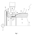
- an exhaust system 1 only partially shown here in an exhaust line 23 at least one here also only partially illustrated decoupling element 2, for example.
- the exhaust system 1 is housed together with the internal combustion engine in a vehicle, not shown here, and expediently arranged on an underbody of the vehicle.
- the exhaust gas line 23 contains, for example, a catalyst, not shown, and a silencer, not shown.
- the decoupling element 2 comprises an elastic body 3, which is designed to guide exhaust gas as a hollow body or surrounds a cavity 4 in a circumferential direction 5.
- the circumferential direction 5 is related to a longitudinal central axis 6 of the decoupling element 2.
- the decoupling element 2 has In addition, at least one support ring 7 which is fixedly connected to the body 3.
- the support ring 7 encloses an axial end portion 8 of the body 3 in the circumferential direction 5 from the outside or on an outer side. Accordingly, the support ring 7 is attached to the outside of the end portion 8 and the end portion 8 is inserted into the support ring 7.
- Support ring 7 and end portion 8 are fixedly connected to each other in a suitable manner, for example.
- the decoupling element 2 also has at least one flange 9, with which the decoupling element 2 can be fastened, for example, to a counterflange 10.
- the counter flange 10 may be formed, for example, on an exhaust gas treatment device of the exhaust system 1.
- the counter flange 10 may be formed on a periphery of the exhaust system 1.
- the decoupling element 2 can be configured as a load-bearing decoupling element 2 or as a non-load-bearing decoupling element 2.
- the flange 9 is fixed in the example in each case via an annular disk-shaped sealing element 11 on the counter flange 10, for example. By means not shown here screw.
- the flange 9 is fixed by means of a weld 12 on the support ring 7.
- the weld seam 12 is configured circumferentially in the circumferential direction 5.
- the weld 12 can be arranged externally or attached from the outside, the flange 9 has a nozzle 13 which is inserted into the enclosed by the support ring 9 end portion 8 of the body 3.
- the weld 12 can now be circumferentially mounted outside so that it connects an axial end face 14 of the support ring 7 remote from the body 3 with an outer periphery 15 of the neck 13.
- the weld 12 is comparatively easy to produce, as provided for the production of the weld 12 outboard, circumferential weld for a welding tool 16 is relatively easily accessible, so that, for example, a welding wire 17 is not obstructed by an undercut or the like.
- the weld seam 12 can be realized with high reliability so that it connects said end face 14 of the support ring 7 securely and directly to the outer circumference 15 of the neck 13.
- the radially arranged between the outer periphery 15 of the nozzle 13 and the support ring 7 end portion 8 of the body 3 extends axially to the end face 14 of the support ring 7.
- the circumferential weld 12 can now the end face 14 of the support ring 7, including a axial end face 18 of the end portion 8 with the outer periphery 15 of the nozzle 13 connect.
- said end face 18 of the end section 8 can be incorporated into the weld seam 12, so that ultimately the end section 8 is welded via the weld seam 12 both to the connection piece 13 and to the support ring 7.
- the body 3 is configured at least two layers. Accordingly, the body 3 has at least an inner layer 19 and an outer layer 20, which surrounds the inner layer 19 in the circumferential direction 5.
- the outer layer 20 is expediently designed as wire mesh.
- the inner layer 19 may be configured as Agraff or corrugated pipe. If the body 3 is configured in two layers or in multiple layers, the two layers 19, 20 or all layers 19, 20 of the body 3 can extend to the front side 18 of the end section 8 and accordingly be bridged by the weld seam 12. If, as shown here, the axial end face 18 of the end section 18 projects axially beyond the end face 14 of the support ring 7, the individual layers 19, 20 of the body 3 can be integrated into the weld seam 12.
- the flange 9 each has a radially outwardly projecting from the neck 13, expediently circumferential in the circumferential direction 5 collar 21.
- the flange 9 has a relatively high dimensional stability.
- the collar 21 may, for example, be used for fastening the flange 9 to the counter flange 10.
- an axially angled, preferably circumferential in the circumferential direction 5 board 22 may be formed on the collar 21 distal to the nozzle 13.
- the board 22 is angled toward the body 3 from the collar 21.
- the flange 9 is relatively compact in the radial direction.
- the board 22 is angled away from the body 3 away from the collar 21, whereby the flange 9 builds comparatively compact in the axial direction.
- the support ring 7 has a circumferential collar 24 which projects radially outwards from the support ring 7.
- the collar 24 of the support ring 7 is arranged on a side facing away from the weld 12 axial end of the support ring 7.
Landscapes
- Engineering & Computer Science (AREA)
- General Engineering & Computer Science (AREA)
- Mechanical Engineering (AREA)
- Chemical & Material Sciences (AREA)
- Combustion & Propulsion (AREA)
- Physics & Mathematics (AREA)
- Plasma & Fusion (AREA)
- Exhaust Silencers (AREA)
- Processes For Solid Components From Exhaust (AREA)
- Exhaust Gas After Treatment (AREA)
Abstract
Description
- Die vorliegende Erfindung betrifft ein Entkoppelelement für eine Abgasanlage einer Brennkraftmaschine, insbesondere eines Kraftfahrzeugs. Die vorliegende Erfindung betrifft außerdem eine Abgasanlage für eine Brennkraftmaschine, insbesondere eines Kraftfahrzeugs, die mit wenigstens einem derartigen Entkoppelelement ausgestattet ist.
- Entkoppelelemente kommen bei Abgasanlagen vorwiegend zur Entkopplung von Lastwechselbewegungen und Schwingungen zwischen Motor und Abgasanlage zum Einsatz. Bspw. kann ein derartiges Entkoppelelement als abgasführender Abschnitt eines Abgasstrangs zwischen einem motornahen Katalysator und einem Mittelschalldämpfer der Abgasanlage im Abgasstrang angeordnet sein. Hierzu umfasst ein derartiges Entkoppelelement einen elastischen, abgasführenden Körper, der an seinen Längsenden auf geeignete Weise in den Abgasstrang eingebunden werden kann. Dabei kann besagter Körper an seinen Längsenden jeweils mit einem Rohrstück verbunden sein oder zumindest an einem Längsende bereits mit einer Abgasbehandlungseinrichtung der Abgasanlage fest verbunden sein. Der Körper des Entkoppelelements besitzt einen für die auftretenden Temperaturen und Drücke der Abgasanlage geeigneten Aufbau und besteht aus entsprechenden Materialien. Am jeweiligen axialen Ende des Körpers kann ein Stützring vorgesehen sein, der einen axialen Endabschnitt des Körpers von außen in der Umfangsrichtung umschließt. Für bestimmte Einbausituationen kann das Entkoppelelement außerdem mit wenigstens einem Flansch ausgestattet sein, der mittels einer Schweißnaht am Stützring befestigt ist. Mit Hilfe des Flansches kann das Entkoppelelement bspw. an eine Abgasbehandlungseinrichtung angeschlossen werden. Ebenso ist es möglich, mit Hilfe eines derartigen Flansches das Entkoppelelement an einer Peripherie der Abgasanlage, z. B. an einem Unterboden eines Fahrzeugs, zu befestigen.
- Für den Fall, dass der Stützring in eine Aufnahmeöffnung des Flansches eingesetzt wird, und für den Fall, dass der jeweilige axiale Endabschnitt des Körpers fertigungsbedingt über den Stützring axial vorsteht, besteht beim Herstellen der Schweißverbindung zwischen Flansch und Stützring die Gefahr, dass sich die Schweißnaht vorrangig mit der axialen Stirnseite des Endabschnitts verbindet und nur nachrangig oder gar nicht mit dem Stützring, sodass die Schweißverbindung letztlich nur zwischen der Stirnseite des Körpers und dem Flansch besteht. Denn bei einer derartigen Konstellation entsteht eine innen liegende Schweißstelle, die außerdem durch eine im Flansch ausgebildete, als Axialanschlag für den Stützring dienende Ringschulter weitgehend verdeckt sein kann, was die Zugänglichkeit der Schweißstelle erschwert. Um dies zu vermeiden, ist eine aufwändige Vorbereitung des Entkoppelelements im Bereich des Stützrings erforderlich, beispielsweise um das am Stützring axial überstehende Ende des zugehörigen Endabschnitts zu entfernen.
- Die vorliegende Erfindung beschäftigt sich mit dem Problem, für ein derartiges Entkoppelelement bzw. für eine damit ausgestattete Abgasanlage eine verbesserte oder zumindest eine andere Ausführungsform anzugeben, die sich insbesondere durch eine preiswert realisierbare Schweißverbindung zwischen Flansch und Stützring mit ausreichender Zuverlässigkeit auszeichnet.
- Dieses Problem wird erfindungsgemäß durch die Gegenstände der unabhängigen Ansprüche gelöst. Vorteilhafte Ausführungsformen sind Gegenstand der abhängigen Ansprüche.
- Die Erfindung beruht auf dem allgemeinen Gedanken, den Flansch mit einem Stutzen auszustatten, sodass der Stutzen in den vom Stützring umschlossenen Endabschnitt des Körpers axial eingesteckt werden kann. In der Folge kann die Schweißnaht außen umlaufend angebracht werden. Insbesondere durch die bessere Einsehbarkeit der Schweißstelle lässt sich die Schweißnaht nun vergleichsweise einfach so realisieren, dass sie eine axiale Stirnseite des Stützrings mit einem Außenumfang des Stutzens des Flansches verbindet.
- Durch die vorgeschlagene Anordnung lässt sich die gewünschte Schweißverbindung zwischen Stützring und Flansch vergleichsweise leicht mit hoher Zuverlässigkeit herstellen. Insbesondere kann somit auf eine kostenintensive Vorbereitung der Schweißstelle verzichtet werden.
- Entsprechend einer besonders vorteilhaften Ausführungsform kann sich der radial zwischen dem Außenumfang des Stutzens und dem Stützring angeordnete Endabschnitt des Körpers axial bis zur Stirnseite des Stützrings erstrecken, wobei dann die umlaufende Schweißnaht die Stirnseite des Stützrings unter Einschluss einer axialen Stirnseite des Endabschnitts mit dem Außenumfang des Stutzens verbindet. Insbesondere kann dabei die Stirnseite des Endabschnitts in die Schweißnaht eingebunden werden. Letzteres setzt voraus, dass der jeweilige Werkstoff, aus dem der Körper hergestellt ist, zur Herstellung einer derartigen Schweißverbindung kompatibel ist. Hierdurch ergibt sich eine besonders innige Verbindung mit hoher Festigkeit zwischen Flansch, Stützring und Körper.
- Alternativ können Stützring und Endabschnitt des Körpers auch so aufeinander abgestimmt sein, dass die vom Körper wegweisende bzw. abgewandte axiale Stirnseite des Stützrings axial über die axiale Stirnseite des Endabschnitts vorsteht. In diesem Fall überbrückt die Schweißnaht einen radialen Spalt zwischen dem Außenumfang des Stutzens und dem Stützring. Da der Stützring seinerseits auf geeignete Weise, z. B. über eine Lötverbindung oder eine andere Schweißverbindung, mit dem Körper fest verbunden ist, kann auch hierdurch eine ausreichend feste Anbindung des Flansches am Körper realisiert werden.
- Entsprechend einer vorteilhaften Ausführungsform kann der Körper wenigstens zweilagig ausgestaltet sein, wobei eine Innenlage sowie eine Außenlage vorgesehen sind. Die Außenlage umschließt dabei die Innenlage. Zweckmäßig erstrecken sich Außenlage und Innenlage bis in den jeweiligen axialen Endabschnitt und dementsprechend axial bis in den Stützring und ggf. auch durch den Stützring hindurch.
- Zweckmäßig kann die Innenlage als Agraff ausgestaltet sein. Eine derartige Agraff-Struktur ist bspw. zur druckstabilen und flexiblen Ummantelung von Brauseschläuchen allgemein bekannt. Alternativ kann die Innenlage auch als Wellrohr ausgestaltet sein, das ebenfalls eine hohe Flexibilität besitzt. Die Außenlage kann dagegen als Drahtgewebe ausgestaltet sein. Sowohl die Innenlage als auch die Außenlage sind zweckmäßig aus einem metallischen Werkstoff hergestellt, vorzugsweise eine Eisenlegierung.
- Gemäß einer anderen vorteilhaften Ausführungsform können sich nun beide Lagen des Körpers bis zur Stirnseite des Endabschnitts erstrecken und von der Schweißnaht überbrückt sein, sodass zumindest eine der beiden Lagen in die Schweißnaht eingebunden oder ohne Verbindung mit der Schweißnaht von dieser eingeschlossen ist.
- Bei einer anderen Ausführungsform steht die Innenlage axial über die Außenlage vor. In diesem Fall hat die Schweißnaht einen besseren Kontakt zur Innenschicht.
- Bei einer anderen vorteilhaften Ausführungsform kann der Flansch einen radial nach außen vom Stutzen abstehenden, vorzugsweise umlaufenden Kragen aufweisen, der zur Befestigung des Flansches an der Peripherie der Abgasanlage oder an einer Abgasbehandlungseinrichtung vorgesehen ist. Insbesondere lässt sich mit Hilfe des Kragens somit eine Ausgestaltung des Entkoppelelements als tragendes Entkoppelelement realisieren.
- Sofern das Entkoppelelement, insbesondere über seinen Flansch, an einer Peripherie der Abgasanlage befestigt ist, besitzt das Entkoppelelement zusätzlich eine Tragfunktion, sodass es auch als tragendes Entkoppelelement bezeichnet werden kann. Dient ein derartiger Flansch dagegen nur zur Befestigung des Entkoppelelements an einer Abgasbehandlungseinrichtung, übernimmt das Entkoppelelement in der Regel keine tragende Funktion und kann dementsprechend auch als nichttragendes Entkoppelelement bezeichnet werden.
- Bei einer bevorzugten Weiterbildung kann nun der Flansch am Kragen distal zum Stutzen einen axial abgewinkelten, vorzugsweise umlaufenden Bord aufweisen. Mit Hilfe eines derartigen, abgewinkelten Bords kann die Steifigkeit des Flansches, insbesondere im Bereich des Kragens signifikant erhöht werden, was eine stabile Fixierung des Flansches an einem dazu komplementären Gegenflansch vereinfacht.
- Bei einer weiteren vorteilhaften Weiterbildung kann der Bord auf den Körper zu abgewinkelt sein, wodurch das Entkoppelelement im Bereich des Flansches in radialer Richtung vergleichsweise kompakt gestaltet werden kann. Alternativ dazu kann der Bord vom Körper weg abgewinkelt sein, wodurch der Flansch in der Radialrichtung mehr Raum benötigt, um ihn an einem Gegenflansch anbringen zu können, jedoch ist bei einer derartigen Ausführungsform der axiale Raumbedarf des Entkoppelelements im Bereich des Flansches reduziert.
- Beim Flansch handelt es sich bevorzugt um ein Blechformteil. Der Stutzen kann dabei als Durchzug ausgestaltet und insbesondere durch Tiefziehen hergestellt sein.
- Gemäß einer anderen Ausführungsform weist der Stützring einen umlaufenden Kragen auf, der vom Stützring radial nach außen absteht. Insbesondere ist der Kragen des Stützrings an einem von der Schweißnaht abgewandten axialen Ende des Stützrings angeordnet. Mithilfe eines solchen abgewinkelten Kragens kann die Steifigkeit des Stützrings signifikant verbessert werden.
- Eine erfindungsgemäße Abgasanlage zeichnet sich dadurch aus, dass in einen Abgasstrang der Abgasanlage zumindest ein Entkoppelelement der vorstehend beschriebenen Art eingebunden ist. Dabei kann das Entkoppelelement als tragendes Entkoppelelement oder als nicht tragendes Entkoppelelement ausgestaltet sein. Das jeweilige Entkoppelelement kann innerhalb des Abgasstrangs an dem einen Längsende an einen Rohrkörper des Abgasstrangs oder an eine Abgasbehandlungseinrichtung des Abgasstrangs angeschlossen sein. Am anderen Längsende kann das Entkoppelelement an einen anderen Rohrkörper des Abgasstrangs oder an eine andere Abgasbehandlungseinrichtung des Abgasstrangs angeschlossen sein.
- Weitere wichtige Merkmale und Vorteile der Erfindung ergeben sich aus den Unteransprüchen, aus den Zeichnungen und aus der zugehörigen Figurenbeschreibung anhand der Zeichnungen.
- Es versteht sich, dass die vorstehend genannten und die nachstehend noch zu erläuternden Merkmale nicht nur in der jeweils angegebenen Kombination, sondern auch in anderen Kombinationen oder in Alleinstellung verwendbar sind, ohne den Rahmen der vorliegenden Erfindung zu verlassen.
- Bevorzugte Ausführungsbeispiele der Erfindung sind in den Zeichnungen dargestellt und werden in der nachfolgenden Beschreibung näher erläutert, wobei sich gleiche Bezugszeichen auf gleiche oder ähnliche oder funktional gleiche Bauteile beziehen.
- Es zeigen, jeweils schematisch,
- Fig. 1
- einen stark vereinfachten Längsschnitt durch eine Abgasanlage im Bereich eines Flansches eines Entkoppelelements,
- Fig. 2
- eine Ansicht wie in
Fig. 1 , jedoch bei einer anderen Ausführungsform. - Entsprechend den
Figuren 1 und2 kann eine hier nur teilweise dargestellte Abgasanlage 1 in einem Abgasstrang 23 zumindest ein hier ebenfalls nur teilweise dargestelltes Entkoppelelement 2 aufweisen, bspw. um eine schwingungsmäßige und bewegungsmäßige Entkopplung zwischen einer Brennkraftmaschine und der Abgasanlage 1 zu erreichen, welche die Abgase der Brennkraftmaschine abführt. Zweckmäßig ist die Abgasanlage 1 zusammen mit der Brennkraftmaschine in einem hier nicht gezeigten Fahrzeug untergebracht und dabei zweckmäßig an einem Unterboden des Fahrzeugs angeordnet. Der Abgasstrang 23 enthält z.B. einen nicht gezeigten Katalysator sowie einen nicht gezeigten Schalldämpfer. - Das Entkoppelelement 2 umfasst einen elastischen Körper 3, der zum Führen von Abgas als Hohlkörper ausgestaltet ist bzw. einen Hohlraum 4 in einer Umfangsrichtung 5 umschließt. Die Umfangsrichtung 5 ist dabei auf eine Längsmittelachse 6 des Entkoppelelements 2 bezogen. Das Entkoppelelement 2 weist außerdem zumindest einen Stützring 7 auf, der fest mit dem Körper 3 verbunden ist. Außerdem umschließt der Stützring 7 einen axialen Endabschnitt 8 des Körpers 3 in der Umfangsrichtung 5 von außen bzw. an einer Außenseite. Dementsprechend ist der Stützring 7 außen auf den Endabschnitt 8 aufgesteckt bzw. ist der Endabschnitt 8 in den Stützring 7 eingesteckt. Stützring 7 und Endabschnitt 8 sind auf geeignete Weise fest miteinander verbunden, bspw. mittels einer hier nicht gezeigten Schweißverbindung oder mittels einer hier nicht gezeigten Lötverbindung.
- Das Entkoppelelement 2 weist außerdem zumindest einen Flansch 9 auf, mit dem das Entkoppelelement 2 bspw. an einem Gegenflansch 10 befestigt werden kann. Der Gegenflansch 10 kann bspw. an einer Abgasbehandlungseinrichtung der Abgasanlage 1 ausgebildet sein. Ebenso kann der Gegenflansch 10 an einer Peripherie der Abgasanlage 1 ausgebildet sein. Dementsprechend kann das Entkoppelelement 2 als tragendes Entkoppelelement 2 oder als nicht tragendes Entkoppelelement 2 ausgestaltet sein. Der Flansch 9 ist im Beispiel jeweils über ein ringscheibenförmiges Dichtelement 11 am Gegenflansch 10 festgelegt, bspw. mittels hier nicht gezeigter Schraubverbindungen.
- Der Flansch 9 ist mittels einer Schweißnaht 12 am Stützring 7 befestigt. Zweckmäßig ist die Schweißnaht 12 dabei in der Umfangsrichtung 5 umlaufend ausgestaltet. Damit die Schweißnaht 12 außen angeordnet bzw. von außen angebracht werden kann, besitzt der Flansch 9 einen Stutzen 13, der in den vom Stützring 9 umschlossenen Endabschnitt 8 des Körpers 3 eingesteckt ist. Die Schweißnaht 12 kann nun außen umlaufend so angebracht werden, dass sie eine vom Körper 3 abgewandte axiale Stirnseite 14 des Stützrings 7 mit einem Außenumfang 15 des Stutzens 13 verbindet. Durch diese Maßnahme ist die Schweißnaht 12 vergleichsweise einfach herstellbar, da die für die Herstellung der Schweißnaht 12 vorgesehene außen liegende, umlaufende Schweißstelle für ein Schweißwerkzeug 16 relativ gut zugänglich ist, sodass bspw. ein Schweißdraht 17 nicht durch einen Hinterschnitt oder dergleichen behindert ist. In der Folge kann mit hoher Zuverlässigkeit die Schweißnaht 12 so realisiert werden, dass sie besagte Stirnseite 14 des Stützrings 7 sicher und direkt mit dem Außenumfang 15 des Stutzens 13 verbindet.
- Bei den hier gezeigten Beispielen erstreckt sich der radial zwischen dem Außenumfang 15 des Stutzens 13 und dem Stützring 7 angeordnete Endabschnitt 8 des Körpers 3 axial bis zur Stirnseite 14 des Stützrings 7. Die umlaufende Schweißnaht 12 kann nun die Stirnseite 14 des Stützrings 7 unter Einschluss einer axialen Stirnseite 18 des Endabschnitts 8 mit dem Außenumfang 15 des Stutzens 13 verbinden. Insbesondere kann dabei besagte Stirnseite 18 des Endabschnitts 8 in die Schweißnaht 12 eingebunden werden, sodass letztlich der Endabschnitt 8 über die Schweißnaht 12 sowohl mit dem Stutzen 13 als auch mit dem Stützring 7 verschweißt ist.
- Zweckmäßig ist der Körper 3 zumindest zweilagig ausgestaltet. Dementsprechend besitzt der Körper 3 zumindest eine Innenlage 19 und eine Außenlage 20, welche die Innenlage 19 in der Umfangsrichtung 5 umschließt. Die Außenlage 20 ist zweckmäßig als Drahtgewebe ausgestaltet. Die Innenlage 19 kann als Agraff oder als Wellrohr ausgestaltet sein. Sofern der Körper 3 zweilagig oder mehrlagig ausgestaltet ist, können sich die beiden Lagen 19, 20 bzw. können sich alle Lagen 19, 20 des Körpers 3 bis zur Stirnseite 18 des Endabschnitts 8 erstrecken und dementsprechend von der Schweißnaht 12 überbrückt werden. Sofern wie hier gezeigt, die axiale Stirnseite 18 des Endabschnitts 18 axial über die Stirnseite 14 des Stützrings 7 übersteht, können die einzelnen Lagen 19, 20 des Körpers 3 in die Schweißnaht 12 eingebunden werden. Steht dagegen die Stirnseite 14 des Stützrings 7 axial über die Stirnseite 18 des Endabschnitts 8 über, werden die Lagen 19, 20 an der Stirnseite 18 des Endabschnitts 8 von der Schweißnaht 12 im radialen Ringspalt zwischen Stutzen 13 und Stützring 7 eingeschlossen.
- Bei den hier gezeigten Ausführungsformen besitzt der Flansch 9 jeweils einen radial nach außen vom Stutzen 13 abstehenden, zweckmäßig in der Umfangsrichtung 5 umlaufenden Kragen 21. Durch den gegenüber dem Stutzen 13 abgewinkelten Kragen 21 besitzt der Flansch 9 eine vergleichsweise hohe Formstabilität. Der Kragen 21 kann bspw. zum Befestigen des Flansches 9 am Gegenflansch 10 verwendet werden. Zur Aussteifung des Flansches 9 im Bereich des Kragens 21 kann am Kragen 21 distal zum Stutzen 13 ein axial abgewinkelter, vorzugsweise in der Umfangsrichtung 5 umlaufender Bord 22 ausgebildet sein. Bei der in
Fig. 1 gezeigten Ausführungsform ist der Bord 22 auf den Körper 3 zu vom Kragen 21 abgewinkelt. Hierdurch baut der Flansch 9 in der radialen Richtung vergleichsweise kompakt. Bei der inFig. 2 gezeigten Ausführungsform ist der Bord 22 vom Körper 3 weg vom Kragen 21 abgewinkelt, wodurch der Flansch 9 in der Axialrichtung vergleichsweise kompakt baut. - Gemäß der Ausführungsformen der
Fig. 1 und2 weist der Stützring 7 einen umlaufenden Kragen 24 auf, der vom Stützring 7 radial nach außen absteht. Insbesondere ist der Kragen 24 des Stützrings 7 an einem von der Schweißnaht 12 abgewandten axialen Ende des Stützrings 7 angeordnet.
Claims (14)
- Entkoppelelement für eine Abgasanlage (1) einer Brennkraftmaschine,- mit einem elastischen, abgasführenden Körper (3),- mit mindestens einem fest mit dem Körper (3) verbundenen Stützring (7), der einen axialen Endabschnitt (8) des Körpers (3) außen in der Umfangsrichtung (5) umschließt,- mit mindestens einem Flansch (9), der mittels einer Schweißnaht (12) am Stützring (7) befestigt ist,- wobei der Flansch (9) einen Stutzen (13) aufweist, der in den vom Stützring (7) umschlossenen Endabschnitt (8) des Körpers (3) eingesteckt ist,- wobei die Schweißnaht (12) außen umlaufend ausgestaltet ist und eine vom Körper (3) abgewandte axiale Stirnseite (14) des Stützrings (7) mit dem Außenumfang (15) des Stutzens (13) des Flansches (9) verbindet.
- Entkoppelelement nach Anspruch 1,
dadurch gekennzeichnet,
dass sich der radial zwischen dem Außenumfang (15) des Stutzens (13) und dem Stützring (7) angeordnete Endabschnitt (8) des Körpers (3) axial bis zur Stirnseite (14) des Stützrings (7) erstreckt, wobei die umlaufende Schweißnaht (12) die Stirnseite (14) des Stützrings (7) unter Einschluss einer axialen Stirnseite (18) des Endabschnitts (8) mit dem Außenumfang (15) des Stutzens (13) verbindet. - Entkoppelelement nach Anspruch 2,
dadurch gekennzeichnet,
dass die Stirnseite (18) des Endabschnitts (8) in die Schweißnaht (12) eingebunden ist. - Entkoppelelement nach einem der Ansprüche 1 bis 3,
dadurch gekennzeichnet,
dass der Körper (3) wenigstens zweilagig ausgestaltet ist und eine Innenlage (19) sowie eine die Innenlage (19) umschließende Außenlage (20) aufweist. - Entkoppelelement nach Anspruch 4,
dadurch gekennzeichnet,- dass die Innenlage (19) als Agraff oder als Wellrohr ausgestaltet ist,- dass die Außenlage (20) als Drahtgewebe ausgestaltet ist. - Entkoppelelement nach Anspruch 2 oder 3, sowie nach Anspruch 4 oder 5,
dadurch gekennzeichnet,
dass sich beide Lagen (19,20) des Körpers (3) bis zur Stirnseite (18) des Endabschnitts (8) erstrecken und von der Schweißnaht (12) überbrückt sind. - Entkoppelelement nach Anspruch 6,
dadurch gekennzeichnet,
dass die Inneschicht (19) axial über die Außenschicht (20) vorsteht. - Entkoppelelement nach einem der Ansprüche 1 bis 7,
dadurch gekennzeichnet,
dass der Flansch (9) einen radial nach außen vom Stutzen (13) abstehenden, umlaufenden Kragen (21) aufweist. - Entkoppelelement nach Anspruch 8,
dadurch gekennzeichnet,
dass der Flansch (9) am Kragen (21) distal zum Stutzen (13) einen axial abgewinkelten Bord (22) aufweist. - Entkoppelelement nach Anspruch 9,
dadurch gekennzeichnet,
dass der Bord (22) auf den Körper (3) zu abgewinkelt ist. - Entkoppelelement nach Anspruch 9,
dadurch gekennzeichnet,
dass der Bord (22) vom Körper (3) weg abgewinkelt ist. - Entkoppelelement nach einem der Ansprüche 1 bis 11,
dadurch gekennzeichnet,
dass der Stützring (7) einen umlaufenden Kragen (24) aufweist, der radial nach außen vom Stützring (7) absteht. - Entkoppelelement nach Anspruch 12,
dadurch gekennzeichnet,
dass der Kragen (24) des Stützrings (7) an einem von der Schweißnaht (12) abgewandten axialen Ende des Stützrings (7) angeordnet ist. - Abgasanlage für eine Brennkraftmaschine, insbesondere eines Kraftfahrzeugs, mit mindestens einem Entkoppelelement (2) nach einem der Ansprüche 1 bis 13.
Priority Applications (1)
| Application Number | Priority Date | Filing Date | Title |
|---|---|---|---|
| PL12191677T PL2594761T3 (pl) | 2011-11-16 | 2012-11-07 | Element odsprzęgający do układu wydechowego |
Applications Claiming Priority (1)
| Application Number | Priority Date | Filing Date | Title |
|---|---|---|---|
| DE102011086463.6A DE102011086463C5 (de) | 2011-11-16 | 2011-11-16 | Entkoppelelement für eine Abgasanlage |
Publications (3)
| Publication Number | Publication Date |
|---|---|
| EP2594761A2 true EP2594761A2 (de) | 2013-05-22 |
| EP2594761A3 EP2594761A3 (de) | 2017-05-03 |
| EP2594761B1 EP2594761B1 (de) | 2021-12-29 |
Family
ID=47143726
Family Applications (1)
| Application Number | Title | Priority Date | Filing Date |
|---|---|---|---|
| EP12191677.9A Active EP2594761B1 (de) | 2011-11-16 | 2012-11-07 | Entkoppelelement für eine Abgasanlage |
Country Status (5)
| Country | Link |
|---|---|
| US (1) | US9835076B2 (de) |
| EP (1) | EP2594761B1 (de) |
| CN (1) | CN103114899B (de) |
| DE (1) | DE102011086463C5 (de) |
| PL (1) | PL2594761T3 (de) |
Cited By (1)
| Publication number | Priority date | Publication date | Assignee | Title |
|---|---|---|---|---|
| US9835076B2 (en) | 2011-11-16 | 2017-12-05 | Eberspaecher Exhaust Technology Gmbh & Co. Kg | Decoupling element for an exhaust system |
Families Citing this family (6)
| Publication number | Priority date | Publication date | Assignee | Title |
|---|---|---|---|---|
| DE102013111957B4 (de) | 2013-10-30 | 2016-12-01 | Benteler Automobiltechnik Gmbh | Abgasleitungseinheit eines Kraftfahrzeugs |
| MX2018002980A (es) * | 2015-09-14 | 2018-05-28 | Nippon Steel & Sumitomo Metal Corp | Metodo de soldadura de filete y junta soldada de filete. |
| EP3366897B1 (de) * | 2017-02-28 | 2020-04-08 | Sjm Co., Ltd. | Flexibles leitungselement |
| DE102019110603A1 (de) * | 2019-04-24 | 2020-10-29 | Liebherr France Sas | Verfahren zur Herstellung eines Rohres mit Verbindungsflansch |
| DE102019115771A1 (de) * | 2019-06-11 | 2020-12-17 | Eberspächer Exhaust Technology GmbH & Co. KG | Verfahren zur Herstellung einer Anschlussbaugruppe, insbesondere an einer Abgasanlagenkomponente einer Abgasanlage einer Brennkraftmaschine, und Abgasanlagenkomponente |
| CN111810753A (zh) * | 2020-07-10 | 2020-10-23 | 江苏曙光压力容器有限公司 | 用于金属波纹管膨胀节内置环焊缝的强化结构 |
Family Cites Families (21)
| Publication number | Priority date | Publication date | Assignee | Title |
|---|---|---|---|---|
| US2232657A (en) * | 1941-02-18 | Expansion joint and method of | ||
| US3169785A (en) * | 1961-11-09 | 1965-02-16 | Eugene H Ziebold | Bellows expansion unit |
| FR2339126A1 (fr) * | 1976-01-22 | 1977-08-19 | Semt | Systeme de raccordement etanche entre deux elements de tuyauterie |
| DE4025652A1 (de) | 1989-10-26 | 1991-05-02 | Hermanns Gebr Kremo Werke | Aufsteckflansch fuer rohrleitungen und verfahren zu seiner herstellung |
| DE69205499T2 (de) * | 1991-06-14 | 1996-03-21 | Toyota Motor Co Ltd | Biegsame Verbindung für ein Auspuffrohr. |
| US5480194A (en) | 1994-11-21 | 1996-01-02 | Boa Ag | Metal expansion joint vibration absorber apparatus for pipe systems |
| US5542715A (en) * | 1995-05-17 | 1996-08-06 | Boa Ag | Metal expansion joint and vibration absorber apparatus for pipe systems |
| EP0848143B1 (de) * | 1996-12-13 | 2003-05-02 | FLEXIDER S.r.l. | Flexible Entkopplungsverbindung, insbesondere für Kraftfahrzeugabgasleitungen |
| US6354332B1 (en) * | 1999-04-30 | 2002-03-12 | Witzenmann Gmbh, Metallschlauch-Fabrik Pforzheim | Coolant line for air conditioning systems |
| FR2821145B1 (fr) * | 2001-02-22 | 2003-12-12 | Renault | Brides d'echappement minces galbees |
| DE10158877A1 (de) * | 2001-11-30 | 2003-06-12 | Iwka Balg Und Kompensatoren Te | Verfahren und Vorrichtung zum Verbinden von Teilen einer Abgasanlage |
| DE102004010815A1 (de) | 2004-03-05 | 2005-09-29 | Benteler Automobiltechnik Gmbh | Anordnung zur Fixierung eines Abgaskrümmers auf dem Zylinderkopf einer Brennkraftmaschine |
| DE102005048909A1 (de) * | 2005-10-10 | 2007-04-12 | J. Eberspächer GmbH & Co. KG | Bauteil einer Abgasanlage |
| DE102006011091A1 (de) * | 2006-03-08 | 2007-09-13 | J. Eberspächer GmbH & Co. KG | Komponente einer Abgasanlage |
| DE102006020608B4 (de) | 2006-05-02 | 2009-04-23 | Benteler Automobiltechnik Gmbh | Anordnung und Verfahren zur Fixierung eines Abgasrohrs an einem Zylinderkopf |
| DE202006018593U1 (de) * | 2006-12-08 | 2008-04-17 | Witzenmann Gmbh | Entkoppelelement |
| DE202007006720U1 (de) | 2007-05-10 | 2008-09-18 | Witzenmann Gmbh | Entkoppelelement mit Verlängerung |
| DE102007050968B4 (de) * | 2007-10-25 | 2025-02-13 | Purem GmbH | Blechbauteil, insbesondere einer Abgasanlage |
| JP4815522B2 (ja) * | 2009-09-30 | 2011-11-16 | 本田技研工業株式会社 | フレキシブルチューブ |
| US8382165B2 (en) * | 2010-11-09 | 2013-02-26 | Tru-Flex Metal Hose, Llc | Exhaust connection member with preformed braided cover |
| DE102011086463C5 (de) | 2011-11-16 | 2021-11-18 | Purem GmbH | Entkoppelelement für eine Abgasanlage |
-
2011
- 2011-11-16 DE DE102011086463.6A patent/DE102011086463C5/de active Active
-
2012
- 2012-11-07 PL PL12191677T patent/PL2594761T3/pl unknown
- 2012-11-07 EP EP12191677.9A patent/EP2594761B1/de active Active
- 2012-11-15 US US13/678,460 patent/US9835076B2/en active Active
- 2012-11-16 CN CN201210465764.9A patent/CN103114899B/zh active Active
Non-Patent Citations (1)
| Title |
|---|
| None |
Cited By (1)
| Publication number | Priority date | Publication date | Assignee | Title |
|---|---|---|---|---|
| US9835076B2 (en) | 2011-11-16 | 2017-12-05 | Eberspaecher Exhaust Technology Gmbh & Co. Kg | Decoupling element for an exhaust system |
Also Published As
| Publication number | Publication date |
|---|---|
| EP2594761A3 (de) | 2017-05-03 |
| DE102011086463C5 (de) | 2021-11-18 |
| EP2594761B1 (de) | 2021-12-29 |
| PL2594761T3 (pl) | 2022-05-02 |
| US9835076B2 (en) | 2017-12-05 |
| CN103114899B (zh) | 2015-10-21 |
| CN103114899A (zh) | 2013-05-22 |
| US20130313819A1 (en) | 2013-11-28 |
| DE102011086463B4 (de) | 2015-01-08 |
| DE102011086463A1 (de) | 2013-05-16 |
Similar Documents
| Publication | Publication Date | Title |
|---|---|---|
| DE102011086463B4 (de) | Entkoppelelement für eine Abgasanlage | |
| EP1887194B1 (de) | Abgasreinigungseinrichtung | |
| EP2420656B1 (de) | Abgasreinigungsvorrichtung, Abgasanlage, Ausbauverfahren | |
| EP2261475A1 (de) | Abgasreinigungseinrichtung | |
| EP2105588A1 (de) | Abgasbehandlungseinrichtung | |
| EP1715155B1 (de) | Abgasanlage und zugehörige Abgasbehandlungsvorrichtung | |
| DE19517462A1 (de) | Endrohr einer Abgasanlage | |
| EP1149992A1 (de) | Abgasvorrichtung einer Abgasanlage, insbesondere Kraftfahrzeug-Katalysator in Modulbauweise | |
| EP1832726A2 (de) | Komponente einer Abgasanlage | |
| EP2639423B1 (de) | Schalldämpfer-einheit | |
| EP2799681A1 (de) | Abgasanlagenkomponente | |
| EP3530898B1 (de) | Abgasanlage | |
| DE4202079C2 (de) | Abgasanlage für Brennkraftmaschinen | |
| EP2461001B1 (de) | Fahrzeugbauteil | |
| EP3173595B1 (de) | Schalldämpfer | |
| EP1772603B1 (de) | Bauteil einer Abgasanlage | |
| EP1531242B1 (de) | Entkoppelelement für Abgasanlagen | |
| EP2474722A2 (de) | Flanschbauteil und Herstellungsverfahren | |
| DE19951714C2 (de) | Heizungsanlage eines Kraftfahrzeuges | |
| EP1118749B1 (de) | Abgaskatalysator | |
| DE19962311B4 (de) | Katalytische Abgasreinigungsvorrichtung | |
| DE102008008352A1 (de) | Bauteilverbindung | |
| DE29605418U1 (de) | Start-Katalysator und Abgasanlage | |
| EP4311919B1 (de) | Abgasführungskomponente für eine abgasanlage einer brennkraftmaschine | |
| DE102015100994A1 (de) | Hitzeschildbaugruppe für eine Fahrzeugabgasanlage sowie Abgasanlagenbauteil eines Kraftfahrzeugs |
Legal Events
| Date | Code | Title | Description |
|---|---|---|---|
| PUAI | Public reference made under article 153(3) epc to a published international application that has entered the european phase |
Free format text: ORIGINAL CODE: 0009012 |
|
| AK | Designated contracting states |
Kind code of ref document: A2 Designated state(s): AL AT BE BG CH CY CZ DE DK EE ES FI FR GB GR HR HU IE IS IT LI LT LU LV MC MK MT NL NO PL PT RO RS SE SI SK SM TR |
|
| AX | Request for extension of the european patent |
Extension state: BA ME |
|
| RAP1 | Party data changed (applicant data changed or rights of an application transferred) |
Owner name: EBERSPAECHER EXHAUST TECHNOLOGY GMBH & CO. KG |
|
| PUAL | Search report despatched |
Free format text: ORIGINAL CODE: 0009013 |
|
| AK | Designated contracting states |
Kind code of ref document: A3 Designated state(s): AL AT BE BG CH CY CZ DE DK EE ES FI FR GB GR HR HU IE IS IT LI LT LU LV MC MK MT NL NO PL PT RO RS SE SI SK SM TR |
|
| AX | Request for extension of the european patent |
Extension state: BA ME |
|
| RIC1 | Information provided on ipc code assigned before grant |
Ipc: F16L 27/11 20060101ALI20170325BHEP Ipc: F16L 27/111 20060101ALI20170325BHEP Ipc: F01N 13/18 20100101AFI20170325BHEP |
|
| STAA | Information on the status of an ep patent application or granted ep patent |
Free format text: STATUS: REQUEST FOR EXAMINATION WAS MADE |
|
| STAA | Information on the status of an ep patent application or granted ep patent |
Free format text: STATUS: EXAMINATION IS IN PROGRESS |
|
| 17P | Request for examination filed |
Effective date: 20170904 |
|
| RBV | Designated contracting states (corrected) |
Designated state(s): AL AT BE BG CH CY CZ DE DK EE ES FI FR GB GR HR HU IE IS IT LI LT LU LV MC MK MT NL NO PL PT RO RS SE SI SK SM TR |
|
| 17Q | First examination report despatched |
Effective date: 20171011 |
|
| GRAP | Despatch of communication of intention to grant a patent |
Free format text: ORIGINAL CODE: EPIDOSNIGR1 |
|
| STAA | Information on the status of an ep patent application or granted ep patent |
Free format text: STATUS: GRANT OF PATENT IS INTENDED |
|
| RIC1 | Information provided on ipc code assigned before grant |
Ipc: F01N 13/18 20100101AFI20210125BHEP Ipc: F16L 27/111 20060101ALI20210125BHEP Ipc: F16L 27/11 20060101ALI20210125BHEP Ipc: B23K 9/028 20060101ALI20210125BHEP |
|
| INTG | Intention to grant announced |
Effective date: 20210215 |
|
| GRAJ | Information related to disapproval of communication of intention to grant by the applicant or resumption of examination proceedings by the epo deleted |
Free format text: ORIGINAL CODE: EPIDOSDIGR1 |
|
| STAA | Information on the status of an ep patent application or granted ep patent |
Free format text: STATUS: EXAMINATION IS IN PROGRESS |
|
| INTC | Intention to grant announced (deleted) | ||
| GRAS | Grant fee paid |
Free format text: ORIGINAL CODE: EPIDOSNIGR3 |
|
| STAA | Information on the status of an ep patent application or granted ep patent |
Free format text: STATUS: GRANT OF PATENT IS INTENDED |
|
| GRAP | Despatch of communication of intention to grant a patent |
Free format text: ORIGINAL CODE: EPIDOSNIGR1 |
|
| RIC1 | Information provided on ipc code assigned before grant |
Ipc: F01N 13/18 20100101AFI20210617BHEP Ipc: F16L 27/111 20060101ALI20210617BHEP Ipc: F16L 27/11 20060101ALI20210617BHEP Ipc: B23K 9/028 20060101ALI20210617BHEP Ipc: F16L 27/10 20060101ALI20210617BHEP |
|
| INTG | Intention to grant announced |
Effective date: 20210720 |
|
| RAP1 | Party data changed (applicant data changed or rights of an application transferred) |
Owner name: PUREM GMBH |
|
| GRAA | (expected) grant |
Free format text: ORIGINAL CODE: 0009210 |
|
| STAA | Information on the status of an ep patent application or granted ep patent |
Free format text: STATUS: THE PATENT HAS BEEN GRANTED |
|
| AK | Designated contracting states |
Kind code of ref document: B1 Designated state(s): AL AT BE BG CH CY CZ DE DK EE ES FI FR GB GR HR HU IE IS IT LI LT LU LV MC MK MT NL NO PL PT RO RS SE SI SK SM TR |
|
| REG | Reference to a national code |
Ref country code: GB Ref legal event code: FG4D Free format text: NOT ENGLISH |
|
| REG | Reference to a national code |
Ref country code: CH Ref legal event code: EP |
|
| REG | Reference to a national code |
Ref country code: AT Ref legal event code: REF Ref document number: 1458842 Country of ref document: AT Kind code of ref document: T Effective date: 20220115 |
|
| REG | Reference to a national code |
Ref country code: IE Ref legal event code: FG4D Free format text: LANGUAGE OF EP DOCUMENT: GERMAN |
|
| REG | Reference to a national code |
Ref country code: DE Ref legal event code: R096 Ref document number: 502012016963 Country of ref document: DE |
|
| REG | Reference to a national code |
Ref country code: SE Ref legal event code: TRGR |
|
| REG | Reference to a national code |
Ref country code: LT Ref legal event code: MG9D |
|
| PG25 | Lapsed in a contracting state [announced via postgrant information from national office to epo] |
Ref country code: RS Free format text: LAPSE BECAUSE OF FAILURE TO SUBMIT A TRANSLATION OF THE DESCRIPTION OR TO PAY THE FEE WITHIN THE PRESCRIBED TIME-LIMIT Effective date: 20211229 Ref country code: LT Free format text: LAPSE BECAUSE OF FAILURE TO SUBMIT A TRANSLATION OF THE DESCRIPTION OR TO PAY THE FEE WITHIN THE PRESCRIBED TIME-LIMIT Effective date: 20211229 Ref country code: FI Free format text: LAPSE BECAUSE OF FAILURE TO SUBMIT A TRANSLATION OF THE DESCRIPTION OR TO PAY THE FEE WITHIN THE PRESCRIBED TIME-LIMIT Effective date: 20211229 Ref country code: BG Free format text: LAPSE BECAUSE OF FAILURE TO SUBMIT A TRANSLATION OF THE DESCRIPTION OR TO PAY THE FEE WITHIN THE PRESCRIBED TIME-LIMIT Effective date: 20220329 |
|
| REG | Reference to a national code |
Ref country code: NL Ref legal event code: MP Effective date: 20211229 |
|
| PG25 | Lapsed in a contracting state [announced via postgrant information from national office to epo] |
Ref country code: NO Free format text: LAPSE BECAUSE OF FAILURE TO SUBMIT A TRANSLATION OF THE DESCRIPTION OR TO PAY THE FEE WITHIN THE PRESCRIBED TIME-LIMIT Effective date: 20220329 Ref country code: LV Free format text: LAPSE BECAUSE OF FAILURE TO SUBMIT A TRANSLATION OF THE DESCRIPTION OR TO PAY THE FEE WITHIN THE PRESCRIBED TIME-LIMIT Effective date: 20211229 Ref country code: HR Free format text: LAPSE BECAUSE OF FAILURE TO SUBMIT A TRANSLATION OF THE DESCRIPTION OR TO PAY THE FEE WITHIN THE PRESCRIBED TIME-LIMIT Effective date: 20211229 Ref country code: GR Free format text: LAPSE BECAUSE OF FAILURE TO SUBMIT A TRANSLATION OF THE DESCRIPTION OR TO PAY THE FEE WITHIN THE PRESCRIBED TIME-LIMIT Effective date: 20220330 |
|
| PG25 | Lapsed in a contracting state [announced via postgrant information from national office to epo] |
Ref country code: NL Free format text: LAPSE BECAUSE OF FAILURE TO SUBMIT A TRANSLATION OF THE DESCRIPTION OR TO PAY THE FEE WITHIN THE PRESCRIBED TIME-LIMIT Effective date: 20211229 |
|
| PG25 | Lapsed in a contracting state [announced via postgrant information from national office to epo] |
Ref country code: SM Free format text: LAPSE BECAUSE OF FAILURE TO SUBMIT A TRANSLATION OF THE DESCRIPTION OR TO PAY THE FEE WITHIN THE PRESCRIBED TIME-LIMIT Effective date: 20211229 Ref country code: SK Free format text: LAPSE BECAUSE OF FAILURE TO SUBMIT A TRANSLATION OF THE DESCRIPTION OR TO PAY THE FEE WITHIN THE PRESCRIBED TIME-LIMIT Effective date: 20211229 Ref country code: RO Free format text: LAPSE BECAUSE OF FAILURE TO SUBMIT A TRANSLATION OF THE DESCRIPTION OR TO PAY THE FEE WITHIN THE PRESCRIBED TIME-LIMIT Effective date: 20211229 Ref country code: PT Free format text: LAPSE BECAUSE OF FAILURE TO SUBMIT A TRANSLATION OF THE DESCRIPTION OR TO PAY THE FEE WITHIN THE PRESCRIBED TIME-LIMIT Effective date: 20220429 Ref country code: ES Free format text: LAPSE BECAUSE OF FAILURE TO SUBMIT A TRANSLATION OF THE DESCRIPTION OR TO PAY THE FEE WITHIN THE PRESCRIBED TIME-LIMIT Effective date: 20211229 Ref country code: EE Free format text: LAPSE BECAUSE OF FAILURE TO SUBMIT A TRANSLATION OF THE DESCRIPTION OR TO PAY THE FEE WITHIN THE PRESCRIBED TIME-LIMIT Effective date: 20211229 |
|
| PG25 | Lapsed in a contracting state [announced via postgrant information from national office to epo] |
Ref country code: IS Free format text: LAPSE BECAUSE OF FAILURE TO SUBMIT A TRANSLATION OF THE DESCRIPTION OR TO PAY THE FEE WITHIN THE PRESCRIBED TIME-LIMIT Effective date: 20220429 |
|
| REG | Reference to a national code |
Ref country code: DE Ref legal event code: R097 Ref document number: 502012016963 Country of ref document: DE |
|
| PG25 | Lapsed in a contracting state [announced via postgrant information from national office to epo] |
Ref country code: DK Free format text: LAPSE BECAUSE OF FAILURE TO SUBMIT A TRANSLATION OF THE DESCRIPTION OR TO PAY THE FEE WITHIN THE PRESCRIBED TIME-LIMIT Effective date: 20211229 Ref country code: AL Free format text: LAPSE BECAUSE OF FAILURE TO SUBMIT A TRANSLATION OF THE DESCRIPTION OR TO PAY THE FEE WITHIN THE PRESCRIBED TIME-LIMIT Effective date: 20211229 |
|
| PLBE | No opposition filed within time limit |
Free format text: ORIGINAL CODE: 0009261 |
|
| STAA | Information on the status of an ep patent application or granted ep patent |
Free format text: STATUS: NO OPPOSITION FILED WITHIN TIME LIMIT |
|
| 26N | No opposition filed |
Effective date: 20220930 |
|
| PG25 | Lapsed in a contracting state [announced via postgrant information from national office to epo] |
Ref country code: SI Free format text: LAPSE BECAUSE OF FAILURE TO SUBMIT A TRANSLATION OF THE DESCRIPTION OR TO PAY THE FEE WITHIN THE PRESCRIBED TIME-LIMIT Effective date: 20211229 |
|
| PG25 | Lapsed in a contracting state [announced via postgrant information from national office to epo] |
Ref country code: MC Free format text: LAPSE BECAUSE OF FAILURE TO SUBMIT A TRANSLATION OF THE DESCRIPTION OR TO PAY THE FEE WITHIN THE PRESCRIBED TIME-LIMIT Effective date: 20211229 |
|
| REG | Reference to a national code |
Ref country code: CH Ref legal event code: PL |
|
| REG | Reference to a national code |
Ref country code: BE Ref legal event code: MM Effective date: 20221130 |
|
| PG25 | Lapsed in a contracting state [announced via postgrant information from national office to epo] |
Ref country code: LI Free format text: LAPSE BECAUSE OF NON-PAYMENT OF DUE FEES Effective date: 20221130 Ref country code: CH Free format text: LAPSE BECAUSE OF NON-PAYMENT OF DUE FEES Effective date: 20221130 |
|
| PG25 | Lapsed in a contracting state [announced via postgrant information from national office to epo] |
Ref country code: LU Free format text: LAPSE BECAUSE OF NON-PAYMENT OF DUE FEES Effective date: 20221107 |
|
| PG25 | Lapsed in a contracting state [announced via postgrant information from national office to epo] |
Ref country code: IE Free format text: LAPSE BECAUSE OF NON-PAYMENT OF DUE FEES Effective date: 20221107 |
|
| PG25 | Lapsed in a contracting state [announced via postgrant information from national office to epo] |
Ref country code: BE Free format text: LAPSE BECAUSE OF NON-PAYMENT OF DUE FEES Effective date: 20221130 |
|
| REG | Reference to a national code |
Ref country code: AT Ref legal event code: MM01 Ref document number: 1458842 Country of ref document: AT Kind code of ref document: T Effective date: 20221107 |
|
| PG25 | Lapsed in a contracting state [announced via postgrant information from national office to epo] |
Ref country code: AT Free format text: LAPSE BECAUSE OF NON-PAYMENT OF DUE FEES Effective date: 20221107 |
|
| PG25 | Lapsed in a contracting state [announced via postgrant information from national office to epo] |
Ref country code: HU Free format text: LAPSE BECAUSE OF FAILURE TO SUBMIT A TRANSLATION OF THE DESCRIPTION OR TO PAY THE FEE WITHIN THE PRESCRIBED TIME-LIMIT; INVALID AB INITIO Effective date: 20121107 |
|
| PG25 | Lapsed in a contracting state [announced via postgrant information from national office to epo] |
Ref country code: CY Free format text: LAPSE BECAUSE OF FAILURE TO SUBMIT A TRANSLATION OF THE DESCRIPTION OR TO PAY THE FEE WITHIN THE PRESCRIBED TIME-LIMIT Effective date: 20211229 |
|
| PG25 | Lapsed in a contracting state [announced via postgrant information from national office to epo] |
Ref country code: MK Free format text: LAPSE BECAUSE OF FAILURE TO SUBMIT A TRANSLATION OF THE DESCRIPTION OR TO PAY THE FEE WITHIN THE PRESCRIBED TIME-LIMIT Effective date: 20211229 |
|
| PG25 | Lapsed in a contracting state [announced via postgrant information from national office to epo] |
Ref country code: TR Free format text: LAPSE BECAUSE OF FAILURE TO SUBMIT A TRANSLATION OF THE DESCRIPTION OR TO PAY THE FEE WITHIN THE PRESCRIBED TIME-LIMIT Effective date: 20211229 |
|
| PG25 | Lapsed in a contracting state [announced via postgrant information from national office to epo] |
Ref country code: MT Free format text: LAPSE BECAUSE OF FAILURE TO SUBMIT A TRANSLATION OF THE DESCRIPTION OR TO PAY THE FEE WITHIN THE PRESCRIBED TIME-LIMIT Effective date: 20211229 |
|
| PGFP | Annual fee paid to national office [announced via postgrant information from national office to epo] |
Ref country code: DE Payment date: 20251118 Year of fee payment: 14 |
|
| PGFP | Annual fee paid to national office [announced via postgrant information from national office to epo] |
Ref country code: GB Payment date: 20251120 Year of fee payment: 14 |
|
| PGFP | Annual fee paid to national office [announced via postgrant information from national office to epo] |
Ref country code: IT Payment date: 20251128 Year of fee payment: 14 |
|
| PGFP | Annual fee paid to national office [announced via postgrant information from national office to epo] |
Ref country code: FR Payment date: 20251125 Year of fee payment: 14 |
|
| PGFP | Annual fee paid to national office [announced via postgrant information from national office to epo] |
Ref country code: SE Payment date: 20251119 Year of fee payment: 14 |
|
| PGFP | Annual fee paid to national office [announced via postgrant information from national office to epo] |
Ref country code: CZ Payment date: 20251024 Year of fee payment: 14 |
|
| PGFP | Annual fee paid to national office [announced via postgrant information from national office to epo] |
Ref country code: PL Payment date: 20251024 Year of fee payment: 14 |