EP2593342B1 - Sensor assembly for a master cylindre - Google Patents
Sensor assembly for a master cylindre Download PDFInfo
- Publication number
- EP2593342B1 EP2593342B1 EP11735996.8A EP11735996A EP2593342B1 EP 2593342 B1 EP2593342 B1 EP 2593342B1 EP 11735996 A EP11735996 A EP 11735996A EP 2593342 B1 EP2593342 B1 EP 2593342B1
- Authority
- EP
- European Patent Office
- Prior art keywords
- sensor
- master cylinder
- negative pressure
- housing
- displacement sensor
- Prior art date
- Legal status (The legal status is an assumption and is not a legal conclusion. Google has not performed a legal analysis and makes no representation as to the accuracy of the status listed.)
- Active
Links
- 238000006073 displacement reaction Methods 0.000 claims description 96
- 230000004907 flux Effects 0.000 claims description 30
- 238000007789 sealing Methods 0.000 claims description 11
- 230000001419 dependent effect Effects 0.000 claims description 2
- 238000001514 detection method Methods 0.000 description 26
- 238000010586 diagram Methods 0.000 description 11
- 239000012528 membrane Substances 0.000 description 8
- 238000004891 communication Methods 0.000 description 4
- 238000011161 development Methods 0.000 description 4
- 238000005259 measurement Methods 0.000 description 4
- 230000008859 change Effects 0.000 description 3
- 230000003750 conditioning effect Effects 0.000 description 3
- 230000001133 acceleration Effects 0.000 description 2
- 230000003321 amplification Effects 0.000 description 2
- 238000011156 evaluation Methods 0.000 description 2
- 239000000696 magnetic material Substances 0.000 description 2
- 238000013178 mathematical model Methods 0.000 description 2
- 238000000034 method Methods 0.000 description 2
- 238000003199 nucleic acid amplification method Methods 0.000 description 2
- 230000008569 process Effects 0.000 description 2
- 230000001172 regenerating effect Effects 0.000 description 2
- 101100220046 Bos taurus CD36 gene Proteins 0.000 description 1
- 101100315759 Komagataella pastoris PEX4 gene Proteins 0.000 description 1
- 101100407813 Saccharomyces cerevisiae (strain ATCC 204508 / S288c) PEX10 gene Proteins 0.000 description 1
- 101100407812 Schizosaccharomyces pombe (strain 972 / ATCC 24843) pas4 gene Proteins 0.000 description 1
- QJVKUMXDEUEQLH-UHFFFAOYSA-N [B].[Fe].[Nd] Chemical compound [B].[Fe].[Nd] QJVKUMXDEUEQLH-UHFFFAOYSA-N 0.000 description 1
- 229910045601 alloy Inorganic materials 0.000 description 1
- 239000000956 alloy Substances 0.000 description 1
- 229910052782 aluminium Inorganic materials 0.000 description 1
- XAGFODPZIPBFFR-UHFFFAOYSA-N aluminium Chemical compound [Al] XAGFODPZIPBFFR-UHFFFAOYSA-N 0.000 description 1
- 238000004364 calculation method Methods 0.000 description 1
- 230000008878 coupling Effects 0.000 description 1
- 238000010168 coupling process Methods 0.000 description 1
- 238000005859 coupling reaction Methods 0.000 description 1
- 230000002950 deficient Effects 0.000 description 1
- 230000000994 depressogenic effect Effects 0.000 description 1
- 230000000694 effects Effects 0.000 description 1
- 230000005670 electromagnetic radiation Effects 0.000 description 1
- 238000003780 insertion Methods 0.000 description 1
- 230000037431 insertion Effects 0.000 description 1
- 230000005415 magnetization Effects 0.000 description 1
- 238000012544 monitoring process Methods 0.000 description 1
- 229910000595 mu-metal Inorganic materials 0.000 description 1
- 229910001172 neodymium magnet Inorganic materials 0.000 description 1
- 230000003287 optical effect Effects 0.000 description 1
- 230000035699 permeability Effects 0.000 description 1
- 230000004044 response Effects 0.000 description 1
- 230000001953 sensory effect Effects 0.000 description 1
Images


Classifications
-
- B—PERFORMING OPERATIONS; TRANSPORTING
- B60—VEHICLES IN GENERAL
- B60Q—ARRANGEMENT OF SIGNALLING OR LIGHTING DEVICES, THE MOUNTING OR SUPPORTING THEREOF OR CIRCUITS THEREFOR, FOR VEHICLES IN GENERAL
- B60Q1/00—Arrangement of optical signalling or lighting devices, the mounting or supporting thereof or circuits therefor
- B60Q1/26—Arrangement of optical signalling or lighting devices, the mounting or supporting thereof or circuits therefor the devices being primarily intended to indicate the vehicle, or parts thereof, or to give signals, to other traffic
- B60Q1/44—Arrangement of optical signalling or lighting devices, the mounting or supporting thereof or circuits therefor the devices being primarily intended to indicate the vehicle, or parts thereof, or to give signals, to other traffic for indicating braking action or preparation for braking, e.g. by detection of the foot approaching the brake pedal
-
- B—PERFORMING OPERATIONS; TRANSPORTING
- B60—VEHICLES IN GENERAL
- B60T—VEHICLE BRAKE CONTROL SYSTEMS OR PARTS THEREOF; BRAKE CONTROL SYSTEMS OR PARTS THEREOF, IN GENERAL; ARRANGEMENT OF BRAKING ELEMENTS ON VEHICLES IN GENERAL; PORTABLE DEVICES FOR PREVENTING UNWANTED MOVEMENT OF VEHICLES; VEHICLE MODIFICATIONS TO FACILITATE COOLING OF BRAKES
- B60T17/00—Component parts, details, or accessories of power brake systems not covered by groups B60T8/00, B60T13/00 or B60T15/00, or presenting other characteristic features
- B60T17/18—Safety devices; Monitoring
- B60T17/22—Devices for monitoring or checking brake systems; Signal devices
-
- B—PERFORMING OPERATIONS; TRANSPORTING
- B60—VEHICLES IN GENERAL
- B60T—VEHICLE BRAKE CONTROL SYSTEMS OR PARTS THEREOF; BRAKE CONTROL SYSTEMS OR PARTS THEREOF, IN GENERAL; ARRANGEMENT OF BRAKING ELEMENTS ON VEHICLES IN GENERAL; PORTABLE DEVICES FOR PREVENTING UNWANTED MOVEMENT OF VEHICLES; VEHICLE MODIFICATIONS TO FACILITATE COOLING OF BRAKES
- B60T11/00—Transmitting braking action from initiating means to ultimate brake actuator without power assistance or drive or where such assistance or drive is irrelevant
- B60T11/10—Transmitting braking action from initiating means to ultimate brake actuator without power assistance or drive or where such assistance or drive is irrelevant transmitting by fluid means, e.g. hydraulic
- B60T11/16—Master control, e.g. master cylinders
-
- B—PERFORMING OPERATIONS; TRANSPORTING
- B60—VEHICLES IN GENERAL
- B60T—VEHICLE BRAKE CONTROL SYSTEMS OR PARTS THEREOF; BRAKE CONTROL SYSTEMS OR PARTS THEREOF, IN GENERAL; ARRANGEMENT OF BRAKING ELEMENTS ON VEHICLES IN GENERAL; PORTABLE DEVICES FOR PREVENTING UNWANTED MOVEMENT OF VEHICLES; VEHICLE MODIFICATIONS TO FACILITATE COOLING OF BRAKES
- B60T13/00—Transmitting braking action from initiating means to ultimate brake actuator with power assistance or drive; Brake systems incorporating such transmitting means, e.g. air-pressure brake systems
- B60T13/10—Transmitting braking action from initiating means to ultimate brake actuator with power assistance or drive; Brake systems incorporating such transmitting means, e.g. air-pressure brake systems with fluid assistance, drive, or release
- B60T13/24—Transmitting braking action from initiating means to ultimate brake actuator with power assistance or drive; Brake systems incorporating such transmitting means, e.g. air-pressure brake systems with fluid assistance, drive, or release the fluid being gaseous
- B60T13/46—Vacuum systems
- B60T13/52—Vacuum systems indirect, i.e. vacuum booster units
-
- B—PERFORMING OPERATIONS; TRANSPORTING
- B60—VEHICLES IN GENERAL
- B60T—VEHICLE BRAKE CONTROL SYSTEMS OR PARTS THEREOF; BRAKE CONTROL SYSTEMS OR PARTS THEREOF, IN GENERAL; ARRANGEMENT OF BRAKING ELEMENTS ON VEHICLES IN GENERAL; PORTABLE DEVICES FOR PREVENTING UNWANTED MOVEMENT OF VEHICLES; VEHICLE MODIFICATIONS TO FACILITATE COOLING OF BRAKES
- B60T7/00—Brake-action initiating means
- B60T7/02—Brake-action initiating means for personal initiation
- B60T7/04—Brake-action initiating means for personal initiation foot actuated
- B60T7/042—Brake-action initiating means for personal initiation foot actuated by electrical means, e.g. using travel or force sensors
-
- G—PHYSICS
- G01—MEASURING; TESTING
- G01L—MEASURING FORCE, STRESS, TORQUE, WORK, MECHANICAL POWER, MECHANICAL EFFICIENCY, OR FLUID PRESSURE
- G01L5/00—Apparatus for, or methods of, measuring force, work, mechanical power, or torque, specially adapted for specific purposes
- G01L5/28—Apparatus for, or methods of, measuring force, work, mechanical power, or torque, specially adapted for specific purposes for testing brakes
Definitions
- the present disclosure relates generally to the field of automotive brake systems. More specifically, a sensor assembly for use with a master cylinder of a brake system will be described.
- Vacuum brake boosters are used in automobiles to increase the foot force applied by the driver to a brake pedal.
- a conventional vacuum brake booster has a vacuum chamber and a working chamber, which are separated by a piston formed as a membrane.
- the membrane is force-transmitting coupled to an input-side actuator of a master cylinder, which also acts on the foot force applied by the driver.
- a negative pressure is constantly maintained during driving, while the working chamber can be selectively connected to the vacuum chamber or to atmospheric pressure.
- the working chamber is fluidically separated from the vacuum chamber and the working chamber also connected to atmospheric pressure.
- the resulting increase in pressure in the working chamber leads to a pressure difference across the membrane. This pressure difference in turn causes a displacement of the membrane in the direction of the vacuum chamber and thus an amplifying force on the actuating element of the master cylinder.
- a negative pressure sensor is mounted on the brake booster to determine the air pressure.
- the vacuum sensor from defective brake booster disassembled and mounted on the new brake booster, which, however, associated with a lot of time.
- a particular embodiment provides to integrate the vacuum sensor with a position sensor of a brake light switch in a sensor assembly and to provide the entire sensor assembly in the negative pressure region of the master cylinder.
- the sensor assembly comprises a finger-like support element, at the tip of the vacuum sensor and the position sensor are added.
- the carrier is guided with the sensors recorded on the front side through a channel formed in the master cylinder, which opens into the negative pressure region.
- the invention has for its object to provide an alternative and in particular improved assembly concept for a master cylinder sensor assembly.
- a sensor assembly for use with a master cylinder, the master cylinder having an input side actuator and a vacuum portion for communicating with a vacuum brake booster.
- the sensor module comprises a vacuum sensor for detecting a negative pressure in the negative pressure region of the master cylinder, at least one further sensor for detecting a signal generator rigidly coupled to the actuating element of the master cylinder, and a housing accommodating the negative pressure sensor and the at least one further sensor.
- the housing has a housing opening, which allows communication of the vacuum sensor with the negative pressure region of the master cylinder, and a mounting arrangement for mounting the housing on the outside of the master cylinder.
- the mounting arrangement may comprise recesses (for example bores) for receiving screws or other fastening elements with which the housing is mounted on the outside of the master cylinder.
- the mounting arrangement may also include a thread attached to the housing to screw the housing into the master cylinder.
- Another realization of Mounting arrangement includes a housing shape, which makes it possible to mount the housing by means of a press fit on the master cylinder.
- the housing may surround the vacuum sensor and the at least one other sensor on one or more sides.
- the housing can surround the sensors at least on an upper side.
- the housing is thus formed by a plate-shaped element which covers, for example, a recess in the master cylinder.
- the housing surrounds the sensors at least laterally and on an upper side.
- the housing it is conceivable for the housing to surround the sensors at least in regions on an underside adjoining the master cylinder.
- the housing opening may be formed on an underside of the housing adjacent to the master cylinder. However, it would also be conceivable to provide the housing opening laterally or at another point of the housing.
- the sensor module comprises a sealing element for the vacuum-tight sealing of the housing opening with respect to the main cylinder and in particular with respect to its negative pressure region.
- the sealing element may be formed, for example, as a sealing ring surrounding the housing opening.
- the sealing element for sealing the housing opening may also be formed on the master cylinder or may be provided loosely between the master cylinder and the sensor assembly.
- a common electrical connection may be present.
- the common electrical connection can be formed (for example as a plug contact) on the housing.
- the vacuum sensor and the at least one further sensor can be arranged together on a printed circuit board accommodated in the housing.
- the printed circuit board can enable a contacting of the sensors or a signal conditioning circuit provided for this purpose via the common electrical connection.
- the at least one further sensor for detecting the signal generator coupled to the actuating element may be a displacement sensor for detecting a path traveled by the actuating element. Furthermore, the at least one further sensor may be a position sensor for detecting the reaching of a predetermined position of the actuating element. According to an optional further development, the position sensor is part of a brake light switch.
- the displacement sensor can provide an analog signal and, for example, designed as a continuous (eg linear) Hall sensor be.
- the position sensor can provide a binary signal and be executed, for example, as a binary Hall sensor with two switching states.
- the sensor assembly comprises not only the vacuum sensor, but also the displacement sensor and the position sensor. Accordingly, at least three sensors are provided. But there are also conceivable implementations in which both a displacement sensor and a position sensor but no vacuum sensor are provided.
- a circuit device may be provided which is designed to calibrate the displacement sensor on the basis of an output signal of the position sensor.
- the circuit device may be part of the sensor module or may be integrated outside the sensor module (also for example in a control unit).
- the displacement sensor and the position sensor are at a distance from each other. This distance can be selected as a function of a length extension of the signal generator. Both the distance between the displacement sensor and the position sensor and the length dimension of the signal generator can be defined in a direction of movement of the actuating element or the signal generator.
- the distance between the displacement sensor and the position sensor according to a variant can correspond to approximately half the length of the signal generator. Such a distance is advantageous, for example, in the case of an electromagnetic radiation-emitting signal transmitter (for example a magnetic element). Depending on the realization of the sensors and the signal transmitter, however, a different distance between the displacement sensor and the position sensor can be selected.
- the displacement sensor and the position sensor may be configured to detect electromagnetic radiation, such as a magnetic flux density.
- the displacement sensor may be placed such that the displacement sensor in an initial position of the actuator is approximately within a range of a maximum flux density (due to the signal transmitter).
- the sensor module comprises a further, second displacement sensor
- the second displacement sensor can be placed in such a way that, in an initial position of the actuating element, it lies approximately in a range of a further maximum flux density.
- the position sensor may be placed such that the position sensor in a Starting position of the actuator is located approximately in a range between two flux density maxima.
- the accuracy of the position detection can be increased such that an output signal of the displacement sensor can also be used for detecting pedal travel (an additional pedal travel sensor can thus be dispensed with).
- the pedal travel detection is an essential prerequisite for the implementation of an electro-hydraulic brake system, a regenerative braking system ("hybrid brake system”) or similar concepts. Therefore, the sensor assembly presented here can also be used in connection with such braking systems.
- the signal generator can be rigidly coupled to the actuator in different ways. In the simplest case, the signal generator is directly coupled to the actuating element or even identical to the actuating element. Alternatively, the signal generator can also be provided on a rigidly coupled to the actuator structure. This structure may, for example, be a tappet coupled to the actuating element and carrying the signal transmitter.
- the sensor assembly may further include a channel (e.g., within a cartridge) for receiving the plunger.
- the housing opening may be arranged such that the negative pressure sensor communicates via the channel with the negative pressure region of the master cylinder. The housing opening may therefore be formed, for example, by an opening (which is in relation to the plunger) of the channel or else provided within the channel.
- the master cylinder includes the input side actuator and the vacuum section for communicating with a vacuum brake booster.
- the master cylinder assembly may further include the vacuum brake booster itself.
- the master cylinder assembly comprises the actuator coupled to the plunger, which carries the signal generator. Further, a channel for receiving the plunger may be formed on the master cylinder. The channel may belong to the negative pressure region of the master cylinder and be arranged to connect a vacuum chamber of the vacuum brake booster with the housing opening. In this way, communication of the vacuum sensor with the vacuum chamber is made possible.
- a sensor system is provided with a sensor assembly comprising the displacement sensor and the position sensor as well as a circuit device which is designed to calibrate the displacement sensor on the basis of an output signal of the position sensor.
- This sensor system may be used to simulate a pedal travel sensor signal based on the output of the displacement sensor.
- Use of the sensor assembly may further include balancing the trajectory sensed by the displacement sensor and reaching the predetermined position sensed by the position sensor.
- Such adjustment may include, for example, calibrating (an output signal) of the displacement sensor based on an output signal of the position sensor.
- the calibration can be done upon detecting the reaching of the predetermined position (ie, for example, at a switching point of the position sensor).
- the output signal of the displacement sensor can be related to a reference signal.
- an amplification factor for the output signal of the displacement sensor may be set in accordance with the reference signal.
- the output signal of the position sensor can be made plausible.
- This plausibility check may comprise the redundant evaluation of another signal indicative of a braking process.
- Such a signal may, for example, be provided by a longitudinal acceleration sensor or a wheel speed sensor.
- a brake pedal travel and / or a negative pressure in a vacuum brake booster can be determined.
- the respective determination can be made on the basis of a mathematical calculation (eg using a mathematical model).
- Fig. 1 shows an embodiment of a generally designated 10 master cylinder assembly.
- the master cylinder assembly 10 includes a master cylinder 12, a vacuum brake booster 14 fixed to the front side of the master cylinder 12, and a sensor assembly 16 mounted on the outside of the master cylinder 12.
- the vacuum brake booster 14 comprises a housing 18. Within the housing 18, a vacuum chamber 20 and a working chamber 22 are formed. The working chamber 22 is separated from the vacuum chamber 20 by means of a displaceable in the housing 18 in the manner of a piston 24 membrane. The membrane 24 in turn is coupled in a force-transmitting manner with an input rod 25. The input rod 25 is actuated by means of a brake pedal (not shown).
- the master cylinder 12 comprises a housing 26, which is fastened via a sealing element in the form of an O-ring 27 on the housing 18 of the brake booster 14.
- a hydraulic chamber 28 is formed.
- a rigidly coupled to the input rod 25 actuating piston (primary piston) 30 is guided displaceably.
- actuating piston 30 By means of the actuating piston 30, a hydraulic pressure for actuating wheel brakes (not shown) can be built up within the hydraulic chamber 28.
- the brake pressure build-up in the hydraulic chamber 28 is effected by displacing the actuating piston 30 in FIG Fig. 1 to the right.
- the displacement of the actuating piston 30 by means of the brake pedal coupled to the input rod 25 and the membrane 24.
- On the actuating piston 30 acts here on the one hand initiated by the driver in the brake pedal foot force and the other by the brake booster 14 (in a conventional manner) generated amplifying force.
- a plate member 32 is attached to the actuating piston 30 at its end face facing the input rod 25 end face.
- the plate element 32 is arranged concentrically to the actuating piston 30 and protrudes in the radial direction beyond the actuating piston 30 also.
- In the vicinity of the outer periphery of the plate member 32 is a parallel to the actuating piston 30 in the direction of the master cylinder housing 26 extending plunger 34 rigidly attached.
- the plunger 34 is formed as a rod-like element and extends through a formed in the housing 26 channel 36 in a likewise formed in the housing 26 recess 38.
- a signal transmitter element 40 for detection by means of the sensor assembly sixteenth Due to the rigid coupling of the plunger 34 with the actuating piston 30, any translational movement of the actuating piston 30 transmits directly to the signal transmitter element 40. For this reason, detection of a movement or position of the signal transmitter element 40 by means of the sensor assembly 16 allows a statement about a movement or position of the Actuating piston 30.
- the input rod 25, the plate member 32, the plunger 34 and the actuating piston 30 are at least partially disposed in the vacuum chamber 20 of the brake booster 14. Further, a negative pressure area in the master cylinder 12 is defined via the communicating with the vacuum chamber 20 and channel 36 communicating with the channel 36 recess 38 of the master cylinder housing 26. The plunger 34 with the attached signal transmitter element 40 immersed in this negative pressure range.
- Fig. 2 shows an enlarged detail of the Fig. 1 in the area of the sensor assembly 16.
- the sensor assembly 16 includes a housing 42 which is externally mounted on the housing 26 of the master cylinder 12.
- the assembly of the housing 42 of the sensor assembly 16 on the master cylinder housing 26 is such that the recess 38 is closed in the master cylinder housing 26 vacuum-tight.
- a sealing element 44 is provided around the recess 38 between the housing 42 of the sensor assembly 16 and the master cylinder housing 26. In this way prevents air from the environment via the recess 38 and the channel 36 in the master cylinder housing 26 penetrates into the vacuum chamber 20 of the brake booster 14.
- the housing 42 of the sensor assembly 16 is secured to the master cylinder housing 26 by bolts (not shown).
- the housing 42 but also using less stable mounting arrangements on the outside of the master cylinder 12 can be mounted.
- folding or locking connections for the assembly of the housing 42 in question can be mounted.
- the housing 42 comprises a first housing element, which defines a lower side 46 and a side wall 48 of the housing 42, and a second housing element, which is designed as a cover 50 and closes the first housing element on the upper side.
- a printed circuit board 52 (Printed Circuit Board, PCB) is added.
- a vacuum sensor 54, a linear or planar trained displacement sensor 56 and a circuit device 58 are mounted on the circuit board 52.
- the vacuum sensor 54 allows the detection of a negative pressure in the negative pressure region of the brake booster 14.
- an opening 60 formed in the underside 46 of the housing 42 allows communication of the vacuum sensor 54 with the recess 38 formed in the master cylinder housing 26 and thus - via the channel 36 -.
- the vacuum sensor 54 (or the printed circuit board 52) closes the housing opening 60 in a vacuum-tight manner relative to an interior of the housing 42 of the sensor assembly 16.
- the negative pressure sensor 54 itself is arranged in a chamber 64 formed in the interior of the housing 42.
- the housing cover 50 has a cover opening 64 in the region of the chamber 62. For this reason, atmospheric pressure prevails in the interior of the chamber 62 in order to enable a pressure-difference-based negative pressure detection by means of the vacuum sensor 54.
- the chamber 62 itself is vacuum-sealed with respect to the remaining interior of the housing 42.
- the displacement sensor 56 is formed linearly or flat on the printed circuit board 52 and therefore in the sectional view according to Fig. 2 not immediately recognizable.
- the displacement sensor 56 is designed as a continuous or linear Hall sensor for detecting a path traveled by the actuating piston 30.
- the detection of the path traveled by the actuating piston 30 is effected indirectly by detecting the distance covered by the signal transmitter element 40 which is rigidly coupled to the actuating piston 30.
- the signal transmitter element 40 is realized in the present embodiment as a permanent magnet whose magnetic field is detected by means of the designed as a Hall sensor displacement sensor 56.
- the circuitry 58 is electrically coupled to both the vacuum sensor 54 and the displacement sensor 56 and includes appropriate signal conditioning circuitry for the two sensors 54, 56.
- the circuitry 58 is configured as an ASIC (Application Specific Integrated Circuit).
- the circuit device 58 sets its output signals via a in Fig. 2 not shown common electrical connection (for example, a multi-pin electrical connector) an external control unit available.
- an external control unit available.
- the external control unit may be an electronic control unit (ECU).
- the circuit device 58 itself comprises the required control unit functionalities according to the "smart sensor" concept.
- the circuit device 58 can be connected in this case (for example via a CAN bus) to a higher-level control system.
- the recess 38 designed as a helical spring spring element 66 is arranged, which on the signal transmitter element 40 carrying ram 34 a restoring force (in Fig. 2 to the left).
- the spring element 66 ensures that after completion of a braking operation, the plunger 34 with the signal transmitter element 40 always returns to its in Fig. 2 returns to the initial position shown.
- the signal transmitter element 40 is mounted on the slide 34 via a slide 68.
- the carriage 68 in turn is guided in a groove 69 which is formed in a side wall of the recess 38 or a separate signal generator cartridge, guided.
- a hydraulic pressure sensor 70 is provided in the recess 38 of the master cylinder housing 26.
- the hydraulic pressure sensor 70 is fixed to the bottom of the recess 38 and communicates via a bore 72 with the hydraulic chamber 28.
- the bore 72 is sealed hydraulically by means of the pressure sensor 70 with respect to the recess 38.
- the hydraulic pressure sensor 70 is electrically contacted by the circuit device 58.
- the circuit 58 also includes a signal conditioning circuit for the hydraulic pressure sensor 70 and provides a corresponding output signal that can be tapped via the common electrical connection.
- the interior of the housing 42 may not necessarily be formed vacuum-tight. Namely, the vacuum-tight closure of the negative pressure region of the master cylinder 12 is effected via the housing bottom 46 in combination with the circumferential sealing element 44 between the housing bottom 46 and the master cylinder housing 26. A vacuum leak over the housing opening 60 is prevented by the housing opening 60 being vacuum-tight by means of the vacuum sensor 54 (FIGS. or the printed circuit board 52) is closed.
- Fig. 3 shows a second embodiment of the sensor assembly 16, in which there is a negative pressure in the interior of the housing 42.
- similar elements will be given the same reference numerals as in the first embodiment.
- the housing 42 surrounds in accordance with the embodiment Fig. 3 the vacuum sensor 54 and the displacement sensor 56 only laterally and above. The negative pressure region of the master cylinder 12 can therefore continue into the interior of the housing 42.
- the signal transmitter element 40 may be provided in a cartridge for insertion in the recess 38 of the master cylinder housing 26.
- Fig. 4 shows an embodiment of such a cartridge 80.
- the cartridge 80 includes a cartridge housing 82 which internally defines a channel for translatory movement of the transducer element 40.
- the signal transmitter element 40 is preconfigured on the carriage 68 and is of the spring element 66 in its initial position according to Fig. 4 biased.
- the groove 69 is formed for guided movement of the carriage 68. To assemble the cartridge 80, it is inserted into the recess 38 of the master cylinder housing 26 in a first step.
- the plunger 34 is coupled to the carriage 68 (for example by means of a detent, plug or bayonet connection).
- the cartridge housing 82 has an in Fig. 4 not shown opening to a Communication of the vacuum sensor 54 with the interior of the cartridge housing 82 and thus to allow the negative pressure region of the master cylinder 12.
- Fig. 5 shows a further embodiment of a cartridge 80. While it is in the signal transmitter element 40 according to Fig. 4 is a magnetic element for detection by means of a Hall sensor, shows Fig. 5 a signal transmitter element 40 in the form of a lying outside of the cartridge housing 82 reflector, transducer or similar component. The displacement sensor 56 is adjusted accordingly.
- cartridges 80 may either form a separate assembly or combined with the sensor assembly 16 into a single assembly. In the last genanten realization no separate mounting arrangement for the cartridge 80 is required. Rather, the cartridge 80 may be mounted to the master cylinder 12 along with the housing 42 of the sensor assembly 16.
- Fig. 6 shows a further embodiment of a master cylinder assembly 10.
- the sensor assembly 16 includes a position sensor 90 in addition to the vacuum sensor 54 and the displacement sensor 56.
- the position sensor 90 allows the detection of reaching a predetermined position of the signal transmitter element 40 (and thus of the actuating piston 30).
- the position sensor 90 may for example be part of a brake light switch (not shown) and designed as a binary (switching) Hall sensor.
- the displacement sensor 56 provides an analog signal representing a portion of the travel of the actuator piston 30 (and thus the pedal travel)
- the position sensor 90 provides an ON / OFF signal that can be used to turn the brake light on and off.
- Fig. 7 includes the sensor assembly 16 in addition to the vacuum sensor 54 and in addition to the displacement sensor 56 and position sensor 90, a further displacement sensor 56 '.
- the negative pressure sensor 54 in FIG Some realizations are omitted because the negative pressure can also be calculated from a model based on the displacement sensor signal.
- the position sensor 90 can again assume two switching states and be designed, for example, as a binary (switching) Hall sensor.
- the displacement sensor 56 may be a continuous Hall sensor.
- the position sensor 90 configured as a binary Hall sensor comprises a continuous Hall sensor and a comparator connected downstream of the continuous Hall sensor. The comparator thresholds the output of the continuous Hall sensor and outputs either a logical "0" ("OFF") or a logic "1" ("ON") depending on the decision.
- the position sensor 90 provides an ON / OFF signal.
- This ON / OFF signal can be used to switch the brake light on and off. Additionally or alternatively, however, it is also possible to calibrate the analog signal of the displacement sensor 56 using the ON / OFF signal of the position sensor 90, so as to reproduce a pedal travel signal with sufficient accuracy.
- the pedal travel may be determined based on an output of the displacement sensor 56, and a separate pedal travel sensor may be saved.
- the pedal travel detection is an essential prerequisite for the implementation of an electro-hydraulic brake system, a regenerative braking system ("hybrid brake system") or similar concepts. Therefore, the sensor assembly presented here can also be used in connection with such braking systems.
- the master cylinder 12 is made of a non-magnetic material such as aluminum.
- the signal transmitter element 40 comprises a permanent magnet of, for example, a neodymium-iron-boron alloy.
- the Magnetization direction of the signal transmitter element 40 extends parallel to the translational movement direction of the plunger 34 (as in Fig. 7 represented by the south magnetic pole "S" and the north magnetic pole "N").
- Fig. 7 is the resulting course of the magnetic flux density in the initial position of the plunger 34 (solid line), ie when the brake pedal is not actuated, as well as in the end position of the plunger 34 (dotted line), that is illustrated with fully worn brake pedal.
- a flux guide plate 92 is arranged made of a soft magnetic material of high magnetic permeability.
- the flux guide plate 92 shields the sensors 56, 56 ', 90 from external interference fields and therefore allows a higher measurement accuracy.
- the flux guide plate 92 may be made of ⁇ -metal, for example.
- FIG. 7 only schematically drawn courses of the magnetic flux density are in the diagram of Fig. 8 shown more clearly. More specifically illustrated Fig. 8 the location-dependent course of the magnetic flux density B along a parallel to the plunger 34 extending and both the displacement sensor 56 and the position sensor 90 containing straight lines.
- the solid line illustrates as in Fig. 7 the flux density curve in the initial position of the plunger 34 when the brake pedal is not actuated.
- the dotted line indicates the flux density curve in the end position of the plunger 34, so when fully depressed brake pedal.
- the flux density curve has two maxima.
- the two maxima are arranged in the region of the two poles of the magnetic signal transmitter element 40.
- the flux density has an approximately linear course in the section between the two maxima.
- the flux density in the region beyond the two maxima in each case an asymptotic monotonous course.
- Fig. 8 is also the position of the displacement sensor 56 and the position sensor 90 with respect to the Fluß Whyverlaufs shown.
- the fact that the distance between the displacement sensor 56 and the position sensor 90 is selected as a function of a longitudinal extent of the signal transmitter element 40 can be clearly recognized. More specifically, the distance between the displacement sensor 56 and the position sensor 90 corresponds to approximately half the length of the transducer element 40. This fact can be seen from the fact that the displacement sensor 56 in the starting position of the plunger 34 is approximately in the range of a Flußêtmaximums, while the position sensor 90 is in the initial position approximately in the range between the two flux density maxima.
- the detection range of the displacement sensor 56 is selected such that it extends from the location of the highest magnetic flux (flux density maximum) in the direction of the asymptotically monotonous course. If the plunger 34 is moved relative to its starting position in the direction of the end position, the signal transmitter element 40 moves away from the displacement sensor 56, resulting in a monotonous decrease in the magnetic flux of the displacement sensor 56 (and a corresponding monotonic course of a sensor output signal).
- the magnetic flux density has in the in Fig. 8 illustrated sensing range less steep than in the region between the two flux density maxima. To some extent, this detracts from the measurement accuracy, but in favor of a much larger measuring range with monotonically changing magnetic flux.
- Fig. 9 illustrates the course of an output signal of the displacement sensor 56, namely the sensor output voltage, in response to the distance traveled by the plunger 34 and thus by the actuating piston 30 of the master cylinder 12 way.
- the distance traveled by the actuating piston 30 is directly proportional to the pedal travel, so that it is possible to determine from the travel traveled by the actuating piston 30 via a proportionality factor of the pedal travel.
- the distance covered by the actuating piston 30, in turn, is the change in the sensor output voltage of the displacement sensor 56 with the aid of the in Fig. 9 to determine the diagram shown.
- Fig. 9 are both the in Fig. 8 illustrated detection range of the displacement sensor 56 and an alternative detection range for the displacement sensor 56 shown.
- the alternative detection range is arranged between the two flux density maxima.
- the alternative detection range allows a higher accuracy of the position detection, but possibly at the expense of the maximum detectable travel of the actuating piston 30.
- the in Fig. 8 illustrated position of the position sensor 90 are changed, for example, as in Fig. 8 for the displacement sensor 56.
- a further displacement sensor 56 ' may be provided, which is arranged spatially offset with respect to the displacement sensor 56 along the direction of movement of the plunger 34.
- the displacement sensor 56 is provided in the region of a first maximum of the flux density progression and the further sensor 56 'in the region of the second maximum.
- the detection and evaluation of the output signals of both displacement sensors 56, 56 'in creases the accuracy of the position detection.
- the redundancy increases the reliability of the sensor assembly 12.
- a redundant position sensor could similarly be provided.
- the diagram according to Fig. 10 Illustrates in the upper half of the output signal (output voltage) of the position sensor 90 and in the lower half, the output signal (output voltage) of the displacement sensor 56 in dependence on the distance traveled by the actuating piston 30 from its initial position.
- the output signal of the position sensor 90 shows the expected binary progression with a jump of the signal level at a predefined switching point. In practice it has been found that the position of the switching point has no significant temperature dependence.
- the one in the lower half of the diagram of the Fig. 10 illustrated course of the output signal of the displacement sensor 56 shows the expected continuous course in Consistent with the continuous change in the magnetic flux of the displacement sensor 56. It can be clearly seen the strong dependence of the curve of the output signal of the displacement sensor 56 from the temperature.
- a gain factor for the output signal of the displacement sensor 56 is set such that always the in Fig. 10 represented as a solid line represents normalized signal (reference signal).
- the adjustment of the gain as well as the signal gain may be performed in an ECU to obtain a temperature influence compensated signal. Calibration can be performed again each time the brake pedal is pressed.
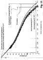
- Fig. 11 shows in a further diagram the course of the sensor output voltage of the displacement sensor 56 as a function of the pedal travel at room temperature and at a temperature of 50 ° C. It can be clearly seen again the strong temperature dependence of the sensor output signal. Also marked in Fig. 11 is the switching point of the position sensor 90. This switching point, which is defined with respect to the initial position of the plunger 34 and the actuating piston 30, has virtually no temperature dependence and is therefore suitable as a reference point for the calibration of the displacement sensor 56th As in Fig. 11 Also, as can be seen, the output of Hall sensor 56 is approaching the asymptotic value 2.5V as the pedal travel increases. This fact allows the displacement sensor 56 to be calibrated based on the amplification factor selection discussed above.
- the output signal of the position sensor 90 can be made plausible on the basis of another signal indicative of a braking process. For example, if we detect a braking operation on the basis of an output signal of a wheel speed sensor or a longitudinal acceleration sensor without the position sensor 90 changing its switching state, it is possible to conclude that an error has occurred.
- Fig. 12 illustrates the relationship between the brake pedal travel as determined, for example, based on the output of the displacement sensor 56 can be, and the negative pressure in the vacuum chamber 20 of the brake booster 14 (see. Fig. 1 ). It has been found that by means of a mathematical model of in Fig. 12 illustrated negative pressure with the also in Fig. 12 shown brake pedal travel can be brought into a relationship. By means of this model can thus be determined on the basis of the output signal of the displacement sensor 56 of the pressure prevailing in the brake booster 14 negative pressure. On the example in Fig. 2 Vacuum sensor shown can therefore be omitted in certain embodiments. In some embodiments, it is also possible to dispense with a separate pedal travel sensor which, in other exemplary embodiments, may be provided in addition to the travel sensor 56.
- the sensor module concept presented here enables simplified mounting of the sensors on the master cylinder.
- Various sensors can be integrated into a single housing, which can be easily mounted on the outside of the master cylinder.
- the sensor signals can be read out via a common electrical connection and plausibilized or calibrated with one another.
Description
Die vorliegende Offenbarung betrifft allgemein das Gebiet der Kraftfahrzeug-Bremsanlagen. Genauer gesagt wird eine Sensorbaugruppe zur Verwendung mit einem Hauptzylinder einer Bremsanlage beschrieben.The present disclosure relates generally to the field of automotive brake systems. More specifically, a sensor assembly for use with a master cylinder of a brake system will be described.
Unterdruck-Bremskraftverstärker werden in Kraftfahrzeugen eingesetzt, um die vom Fahrer an einem Bremspedal aufgebrachte Fußkraft zu verstärken. Ein herkömmlicher Unterdruck-Bremskraftverstärker besitzt eine Unterdruckkammer sowie eine Arbeitskammer, die durch einen als Membran ausgebildeten Kolben voneinander getrennt sind. Die Membran wiederum ist kraftübertragend mit einem eingangsseitigen Betätigungselement eines Hauptzylinders gekoppelt, auf welches auch die vom Fahrer aufgebrachte Fußkraft einwirkt.Vacuum brake boosters are used in automobiles to increase the foot force applied by the driver to a brake pedal. A conventional vacuum brake booster has a vacuum chamber and a working chamber, which are separated by a piston formed as a membrane. The membrane, in turn, is force-transmitting coupled to an input-side actuator of a master cylinder, which also acts on the foot force applied by the driver.
In der Unterdruckkammer wird während des Fahrbetriebs ständig ein Unterdruck aufrechterhalten, während die Arbeitskammer wahlweise mit der Unterdruckkammer oder mit Atmosphärendruck verbunden werden kann. Solange die beiden Kammern miteinander verbunden sind, herrscht in beiden Kammern der gleiche Druck, und die Membran befindet sich in ihrer Ausgangsstellung. Im Rahmen eines Bremsvorgangs wird die Arbeitskammer von der Unterdruckkammer fluidisch getrennt und die Arbeitskammer darüber hinaus mit Atmosphärendruck verbunden. Der daraus resultierende Druckanstieg in der Arbeitskammer führt zu einer Druckdifferenz an der Membran. Diese Druckdifferenz wiederum bewirkt eine Verschiebung der Membran in Richtung der Unterdruckkammer und damit eine Verstärkungskraft am Betätigungselement des Hauptzylinders.In the vacuum chamber, a negative pressure is constantly maintained during driving, while the working chamber can be selectively connected to the vacuum chamber or to atmospheric pressure. As long as the two chambers are connected to each other, the same pressure prevails in both chambers, and the membrane is in its initial position. As part of a braking operation, the working chamber is fluidically separated from the vacuum chamber and the working chamber also connected to atmospheric pressure. The resulting increase in pressure in the working chamber leads to a pressure difference across the membrane. This pressure difference in turn causes a displacement of the membrane in the direction of the vacuum chamber and thus an amplifying force on the actuating element of the master cylinder.
Zur Beurteilung der Leistungsfähigkeit eines Unterdruck-Bremskraftverstärkers ist es wünschenswert, den Druck in der Unterdruckkammer sensorisch zu überwachen. Bei bisherigen Überwachungslösungen, wie sie insbesondere in der
Zur Vermeidung dieser Nachteile wird in der
Der Erfindung liegt die Aufgabe zugrunde, ein alternatives und insbesondere verbessertes Montagekonzept für eine Hauptzylinder-Sensorbaugruppe anzugeben.The invention has for its object to provide an alternative and in particular improved assembly concept for a master cylinder sensor assembly.
Diese Aufgabe wird gelöst durch eine Sensorbaugruppe zur Verwendung mit einem Hauptzylinder, wobei der Hauptzylinder ein eingangsseitiges Betätigungselement und einen Unterdruckbereich zur Kommunikation mit einem Unterdruck-Bremskraftverstärker aufweist. Die Sensorbaugruppe umfasst einen Unterdrucksensor zur Erfassung eines Unterdrucks im Unterdruckbereich des Hauptzylinders, wenigstens einen weiteren Sensor zur Erfassung eines mit dem Betätigungselement des Hauptzylinders starr gekoppelten Signalgebers sowie ein den Unterdrucksensor und den wenigstens einen weiteren Sensor aufnehmendes Gehäuse. Das Gehäuse besitzt eine Gehäuseöffnung, die eine Kommunikation des Unterdrucksensors mit dem Unterdruckbereich des Hauptzylinders gestattet, und eine Befestigungsanordnung zur Montage des Gehäuses außenseitig am Hauptzylinder.This object is achieved by a sensor assembly for use with a master cylinder, the master cylinder having an input side actuator and a vacuum portion for communicating with a vacuum brake booster. The sensor module comprises a vacuum sensor for detecting a negative pressure in the negative pressure region of the master cylinder, at least one further sensor for detecting a signal generator rigidly coupled to the actuating element of the master cylinder, and a housing accommodating the negative pressure sensor and the at least one further sensor. The housing has a housing opening, which allows communication of the vacuum sensor with the negative pressure region of the master cylinder, and a mounting arrangement for mounting the housing on the outside of the master cylinder.
Die Befestigungsanordnung kann Ausnehmungen (zum Beispiel Bohrungen) zur Aufnahme von Schrauben oder anderen Befestigungselementen umfassen, mit denen das Gehäuse außenseitig am Hauptzylinder montiert wird. Alternativ hierzu kann die Befestigungsanordnung auch ein am Gehäuse angebrachtes Gewinde umfassen, um das Gehäuse in den Hauptzylinder einzuschrauben. Eine weitere Realisierung der Befestigungsanordnung umfasst eine Gehäuseformgebung, die es ermöglicht, das Gehäuse mittels eines Presssitzes am Hauptzylinder zu montieren.The mounting arrangement may comprise recesses (for example bores) for receiving screws or other fastening elements with which the housing is mounted on the outside of the master cylinder. Alternatively, the mounting arrangement may also include a thread attached to the housing to screw the housing into the master cylinder. Another realization of Mounting arrangement includes a housing shape, which makes it possible to mount the housing by means of a press fit on the master cylinder.
Das Gehäuse kann den Unterdrucksensor und den wenigstens einen weiteren Sensor auf einer oder mehreren Seiten umgeben. So kann das Gehäuse die Sensoren wenigstens auf einer Oberseite umgeben. Im einfachsten Fall wird das Gehäuse damit von einem plattenförmigen Element gebildet, welches beispielsweise eine Ausnehmung im Hauptzylinder abdeckt. Gemäß einer weiteren Ausgestaltung umgibt das Gehäuse die Sensoren zumindest seitlich und auf einer Oberseite. Ferner ist es denkbar, dass das Gehäuse die Sensoren zumindest bereichsweise auf einer an den Hauptzylinder angrenzenden Unterseite umgibt.The housing may surround the vacuum sensor and the at least one other sensor on one or more sides. Thus, the housing can surround the sensors at least on an upper side. In the simplest case, the housing is thus formed by a plate-shaped element which covers, for example, a recess in the master cylinder. According to a further embodiment, the housing surrounds the sensors at least laterally and on an upper side. Furthermore, it is conceivable for the housing to surround the sensors at least in regions on an underside adjoining the master cylinder.
Die Gehäuseöffnung kann an einer an den Hauptzylinder angrenzenden Unterseite des Gehäuses ausgebildet sein. Es wäre jedoch auch denkbar, die Gehäuseöffnung seitlich oder an einer anderen Stelle des Gehäuses vorzusehen. Gemäß einer Weiterbildung umfasst die Sensorbaugruppe ein Dichtelement zum unterdruckdichten Abdichten der Gehäuseöffnung gegenüber dem Hauptzylinder und insbesondere gegenüber dessen Unterdruckbereich. Das Dichtelement kann beispielsweise als ein die Gehäuseöffnung umgebender Dichtring ausgebildet sein. Das Dichtelement zum Abdichten der Gehäuseöffnung kann auch am Hauptzylinder ausgebildet sein oder aber lose zwischen Hauptzylinder und Sensorbaugruppe vorgesehen werden.The housing opening may be formed on an underside of the housing adjacent to the master cylinder. However, it would also be conceivable to provide the housing opening laterally or at another point of the housing. According to a further development, the sensor module comprises a sealing element for the vacuum-tight sealing of the housing opening with respect to the main cylinder and in particular with respect to its negative pressure region. The sealing element may be formed, for example, as a sealing ring surrounding the housing opening. The sealing element for sealing the housing opening may also be formed on the master cylinder or may be provided loosely between the master cylinder and the sensor assembly.
Für den Unterdrucksensor und den wenigstens einen weiteren Sensor kann ein gemeinsamer elektrischer Anschluss vorhanden sein. Der gemeinsame elektrische Anschluss kann (beispielsweise als Steckkontakt) am Gehäuse ausgebildet sein. Der Unterdrucksensor und der wenigstens eine weitere Sensor können gemeinsam auf einer im Gehäuse aufgenommenen Leiterplatte angeordnet werden. Die Leiterplatte kann eine Kontaktierung der Sensoren oder einer hierfür vorgesehenen Signalaufbereitungsschaltung über den gemeinsamen elektrischen Anschluss ermöglichen.For the vacuum sensor and the at least one further sensor, a common electrical connection may be present. The common electrical connection can be formed (for example as a plug contact) on the housing. The vacuum sensor and the at least one further sensor can be arranged together on a printed circuit board accommodated in the housing. The printed circuit board can enable a contacting of the sensors or a signal conditioning circuit provided for this purpose via the common electrical connection.
Der wenigstens eine weitere Sensor zur Erfassung des mit dem Betätigungselement gekoppelten Signalgebers kann ein Wegsensor zur Erfassung eines vom Betätigungselement zurückgelegten Wegs sein. Ferner kann der wenigstens eine weitere Sensor ein Positionssensor zur Erfassung des Erreichens einer vorgegebenen Position des Betätigungselements sein. Gemäß einer optionalen Weiterbildung ist der Positionssensor Teil eines Bremslichtschalters. Der Wegsensor kann ein analoges Signal bereitstellen und beispielsweise als kontinuierlicher (z.B. linearer) Hall-Sensor ausgebildet sein. Ferner kann der Positionssensor ein binäres Signal bereitstellen und beispielsweise als binärer Hall-Sensor mit zwei Schaltzuständen ausgeführt werden.The at least one further sensor for detecting the signal generator coupled to the actuating element may be a displacement sensor for detecting a path traveled by the actuating element. Furthermore, the at least one further sensor may be a position sensor for detecting the reaching of a predetermined position of the actuating element. According to an optional further development, the position sensor is part of a brake light switch. The displacement sensor can provide an analog signal and, for example, designed as a continuous (eg linear) Hall sensor be. Furthermore, the position sensor can provide a binary signal and be executed, for example, as a binary Hall sensor with two switching states.
Gemäß einer Realisierungsform umfasst die Sensorbaugruppe neben dem Unterdrucksensor sowohl den Wegsensor als auch den Positionssensor. Demgemäss sind wenigstens drei Sensoren vorgesehen. Es sind aber auch Realisierungen denkbar, bei denen sowohl ein Wegsensor als auch ein Positionssensor aber kein Unterdrucksensor vorgesehen sind.According to one embodiment, the sensor assembly comprises not only the vacuum sensor, but also the displacement sensor and the position sensor. Accordingly, at least three sensors are provided. But there are also conceivable implementations in which both a displacement sensor and a position sensor but no vacuum sensor are provided.
Es kann ferner eine Schaltungseinrichtung vorgesehen sein, welche zur Kalibrierung des Wegsensors auf der Grundlage eines Ausgangssignals des Positionssensors ausgebildet ist. Die Schaltungseinrichtung kann Teil der Sensorbaugruppe sein oder aber außerhalb der Sensorbaugruppe (auch beispielsweise in einem Steuergerät) integriert sein.Furthermore, a circuit device may be provided which is designed to calibrate the displacement sensor on the basis of an output signal of the position sensor. The circuit device may be part of the sensor module or may be integrated outside the sensor module (also for example in a control unit).
Gemäß einer Realisierung weisen der Wegsensor und der Positionssensor einen Abstand voneinander auf. Dieser Abstand kann in Abhängigkeit einer Längenausdehnung des Signalgebers gewählt sein. Sowohl der Abstand zwischen dem Wegsensor und dem Positionssensor als auch die Längenausdehnung des Signalgebers können in einer Bewegungsrichtung des Betätigungselements oder des Signalgebers definiert sein.According to an implementation, the displacement sensor and the position sensor are at a distance from each other. This distance can be selected as a function of a length extension of the signal generator. Both the distance between the displacement sensor and the position sensor and the length dimension of the signal generator can be defined in a direction of movement of the actuating element or the signal generator.
Der Abstand zwischen dem Wegsensor und dem Positionssensor kann gemäß einer Variante ungefähr der halben Länge des Signalgebers entsprechen. Ein derartiger Abstand ist beispielsweise bei einem elektromagnetische Strahlung aussendenden Signalgeber (z.B. einem Magnetelement) vorteilhaft. Je nach Realisierung der Sensoren sowie des Signalgebers kann jedoch auch ein anderer Abstand zwischen dem Wegsensor und dem Positionssensor gewählt werden.The distance between the displacement sensor and the position sensor according to a variant can correspond to approximately half the length of the signal generator. Such a distance is advantageous, for example, in the case of an electromagnetic radiation-emitting signal transmitter (for example a magnetic element). Depending on the realization of the sensors and the signal transmitter, however, a different distance between the displacement sensor and the position sensor can be selected.
Der Wegsensor und der Positionssensor können dazu ausgebildet sein, elektromagnetische Strahlung, wie beispielsweise eine magnetische Flussdichte, zu erfassen. Bei einer solchen Implementierung kann der Wegsensor derart platziert sein, dass der Wegsensor in einer Ausgangsstellung des Betätigungselements ungefähr in einem Bereich eines (auf den Signalgeber zurückgehenden) Flussdichtemaximums liegt. Umfasst die Sensorbaugruppe einen weiteren, zweiten Wegsensor, kann der zweite Wegsensor derart platziert sein, dass er in einer Ausgangsstellung des Betätigungselements ungefähr in einem Bereich eines weiteren Flussdichtemaximums liegt. Ferner kann der Positionssensor derart platziert sein, dass der Positionssensor in einer Ausgangsstellung des Betätigungselements ungefähr in einem Bereich zwischen zwei Flussdichtemaxima liegt.The displacement sensor and the position sensor may be configured to detect electromagnetic radiation, such as a magnetic flux density. In such an implementation, the displacement sensor may be placed such that the displacement sensor in an initial position of the actuator is approximately within a range of a maximum flux density (due to the signal transmitter). If the sensor module comprises a further, second displacement sensor, the second displacement sensor can be placed in such a way that, in an initial position of the actuating element, it lies approximately in a range of a further maximum flux density. Furthermore, the position sensor may be placed such that the position sensor in a Starting position of the actuator is located approximately in a range between two flux density maxima.
Mittels des Kalibrierungskonzepts lässt sich die Genauigkeit der Wegerfassung derart erhöhen, dass ein Ausgangssignal des Wegsensors auch zur Pedalwegerfassung herangezogen werden kann (ein zusätzlicher Pedalwegsensor kann damit entfallen). Die Pedalwegerfassung ist eine wesentliche Voraussetzung für die Implementierung einer elektrohydraulischen Bremsanlage, einer regenerativen Bremsanlage ("Hybrid-Bremsanlage") oder ähnlicher Konzepte. Daher kann die hier vorgestellte Sensorbaugruppe auch im Zusammenhang mit solchen Bremsanlagen zum Einsatz gelangen.By means of the calibration concept, the accuracy of the position detection can be increased such that an output signal of the displacement sensor can also be used for detecting pedal travel (an additional pedal travel sensor can thus be dispensed with). The pedal travel detection is an essential prerequisite for the implementation of an electro-hydraulic brake system, a regenerative braking system ("hybrid brake system") or similar concepts. Therefore, the sensor assembly presented here can also be used in connection with such braking systems.
Der Signalgeber kann auf unterschiedliche Art und Weise starr mit dem Betätigungselement gekoppelt werden. Im einfachsten Fall ist der Signalgeber unmittelbar mit dem Betätigungselement gekoppelt oder sogar mit dem Betätigungselement identisch. Alternativ hierzu kann der Signalgeber auch an einer starr mit dem Betätigungselement gekoppelten Struktur vorgesehen werden. Bei dieser Struktur kann es sich beispielsweise um einen mit dem Betätigungselement gekoppelten Stößel handeln, der den Signalgeber trägt. In diesem Fall kann die Sensorbaugruppe ferner einen Kanal (z.B. innerhalb einer Kartusche) zur Aufnahme des Stößels besitzen. Gemäß dieser Ausgestaltung kann die Gehäuseöffnung derart angeordnet sein, dass der Unterdrucksensor über den Kanal mit dem Unterdruckbereich des Hauptzylinders kommuniziert. Die Gehäuseöffnung kann also beispielsweise von einer (in Bezug auf den Stößel) eingangsseitigen Öffnung des Kanals gebildet sein oder aber innerhalb des Kanals vorgesehen werden.The signal generator can be rigidly coupled to the actuator in different ways. In the simplest case, the signal generator is directly coupled to the actuating element or even identical to the actuating element. Alternatively, the signal generator can also be provided on a rigidly coupled to the actuator structure. This structure may, for example, be a tappet coupled to the actuating element and carrying the signal transmitter. In this case, the sensor assembly may further include a channel (e.g., within a cartridge) for receiving the plunger. According to this embodiment, the housing opening may be arranged such that the negative pressure sensor communicates via the channel with the negative pressure region of the master cylinder. The housing opening may therefore be formed, for example, by an opening (which is in relation to the plunger) of the channel or else provided within the channel.
Ebenfalls vorgeschlagen wird eine Hauptzylinderbaugruppe mit einem Hauptzylinder und der hier vorgestellten Sensorbaugruppe. Der Hauptzylinder umfasst das eingangsseitige Betätigungselement und den Unterdruckbereich zur Kommunikation mit einem Unterdruck-Bremskraftverstärker. Die Hauptzylinderbaugruppe kann ferner den Unterdruck-Bremskraftverstärker selbst umfassen.Also proposed is a master cylinder assembly having a master cylinder and the sensor assembly presented herein. The master cylinder includes the input side actuator and the vacuum section for communicating with a vacuum brake booster. The master cylinder assembly may further include the vacuum brake booster itself.
Gemäß einer Weiterbildung umfasst die Hauptzylinderbaugruppe den mit dem Betätigungselement gekoppelten Stößel, welcher den Signalgeber trägt. Ferner kann am Hauptzylinder ein Kanal zur Aufnahme des Stößels ausgebildet sein. Der Kanal kann zum Unterdruckbereich des Hauptzylinders gehören und angeordnet sein, um eine Unterdruckkammer des Unterdruck-Bremskraftverstärkers mit der Gehäuseöffnung zu verbinden. Auf diese Weise wird eine Kommunikation des Unterdrucksensors mit der Unterdruckkammer ermöglicht.According to a development, the master cylinder assembly comprises the actuator coupled to the plunger, which carries the signal generator. Further, a channel for receiving the plunger may be formed on the master cylinder. The channel may belong to the negative pressure region of the master cylinder and be arranged to connect a vacuum chamber of the vacuum brake booster with the housing opening. In this way, communication of the vacuum sensor with the vacuum chamber is made possible.
Ferner wird ein Sensorsystem mit einer den Wegsensor und den Positionssensor umfassenden Sensorbaugruppe sowie eine Schaltungseinrichtung, die zur Kalibrierung des Wegsensors auf der Grundlage eines Ausgangssignals des Positionssensors ausgebildet ist, bereitgestellt. Dieses Sensorsystem kann zur Simulation eines Pedalwegsensorsignals auf der Grundlage des Ausgangssignals des Wegsensors verwendet werden.Furthermore, a sensor system is provided with a sensor assembly comprising the displacement sensor and the position sensor as well as a circuit device which is designed to calibrate the displacement sensor on the basis of an output signal of the position sensor. This sensor system may be used to simulate a pedal travel sensor signal based on the output of the displacement sensor.
Eine Verwendung der Sensorbaugruppe kann ferner ein Abgleichen des zurückgelegten Wegs, der vom Wegsensor erfasst wurde, und des Erreichens der vorgegebenen Position, das vom Positionssensor erfasst wurde, umfassen. Ein derartiger Abgleich kann beispielsweise das Kalibrieren (eines Ausgangssignals) des Wegsensors auf der Grundlage eines Ausgangssignals des Positionssensors beinhalten. Das Kalibrieren kann bei Erfassen des Erreichens der vorgegebenen Position (also beispielsweise an einem Schaltpunkt des Positionssensors) erfolgen. Zum Kalibrieren kann bei Erreichen der vorgegebenen Position das Ausgangssignal des Wegsensors auf ein Referenzsignal bezogen werden. In diesem Zusammenhang kann beispielsweise ein Verstärkungsfaktor für das Ausgangssignal des Wegsensors in Übereinstimmung mit dem Referenzsignal eingestellt werden.Use of the sensor assembly may further include balancing the trajectory sensed by the displacement sensor and reaching the predetermined position sensed by the position sensor. Such adjustment may include, for example, calibrating (an output signal) of the displacement sensor based on an output signal of the position sensor. The calibration can be done upon detecting the reaching of the predetermined position (ie, for example, at a switching point of the position sensor). For calibration, upon reaching the predetermined position, the output signal of the displacement sensor can be related to a reference signal. In this connection, for example, an amplification factor for the output signal of the displacement sensor may be set in accordance with the reference signal.
Das Ausgangssignal des Positionssensors kann plausibilisiert werden. Dieses Plausibilisieren kann das redundante Auswerten eines anderen, auf einen Bremsvorgang hinweisenden Signals umfassen. Ein solches Signal kann beispielsweise von einem Längsbeschleunigungssensor oder einem Raddrehzahlsensor geliefert werden.The output signal of the position sensor can be made plausible. This plausibility check may comprise the redundant evaluation of another signal indicative of a braking process. Such a signal may, for example, be provided by a longitudinal acceleration sensor or a wheel speed sensor.
Auf der Grundlage eines Ausgangssignals des Wegsensors können weitere Größen bestimmt werden. Die Bestimmung dieser Größen ist insbesondere bei einer vorhergehenden Kalibrierung des Wegsensors (und gegebenenfalls einer Plausibilisierung dessen Ausgangssignals) besonders genau und zuverlässig. So kann auf der Grundlage eines Ausgangssignals des Wegsensors ein Bremspedalweg und/oder ein Unterdruck in einem Unterdruck-Bremskraftverstärker ermittelt werden. Die jeweilige Ermittlung kann auf der Grundlage einer mathematischen Berechnung (z.B. unter Verwendung eines mathematischen Modells) erfolgen.On the basis of an output signal of the displacement sensor, further variables can be determined. The determination of these variables is particularly accurate and reliable, especially in the case of a previous calibration of the displacement sensor (and, if appropriate, a plausibility check of its output signal). Thus, on the basis of an output signal of the displacement sensor, a brake pedal travel and / or a negative pressure in a vacuum brake booster can be determined. The respective determination can be made on the basis of a mathematical calculation (eg using a mathematical model).
Weitere Aspekte, Vorteile und Ausgestaltungen der Erfindung ergeben sich aus der nachfolgenden Beschreibung mehrerer Ausführungsbeispiele sowie aus den Figuren. Es zeigt:
- Fig. 1
- eine Schnittansicht eines Ausführungsbeispiels einer Hauptzylinderbaugruppe;
- Fig. 2
- eine Ausschnittsvergrößerung aus
Fig. 1 , die ein erstes Ausführungsbeispiel einer Sensorbaugruppe zeigt; - Fig. 3
- ein zweites Ausführungsbeispiel einer Sensorbaugruppe;
- Fig. 4
- ein erstes Ausführungsbeispiel einer Signalgeberkartusche für eine Sensorbaugruppe;
- Fig. 5
- ein zweites Ausführungsbeispiel einer Signalgeberkartusche für eine Sensorbaugruppe;
- Fig. 6
- ein weiteres Ausführungsbeispiel einer Hauptzylinderbaugruppe;
- Fig. 7
- noch ein Ausführungsbeispiel einer Hauptzylinderbaugruppe;
- Fig. 8
- ein schematisches Diagramm, welches den Verlauf der magnetischen Flussdichte für das Ausführungsbeispiel gemäß
Fig. 8 veranschaulicht; - Fig. 9
- ein schematisches Diagramm, welches den Verlauf eines SensorAusgangssignals und die mögliche Wahl von Erfassungsbereichen veranschaulicht;
- Fig. 10
- ein schematisches Diagramm, welches ein Kalibrierungskonzept veranschaulicht;
- Fig. 11
- ein schematisches Diagramm, welches ein das Kalibrierungskonzept weiter veranschaulicht; und
- Fig. 12
- ein schematisches Diagramm, welches die Bestimmung des Bremskraftverstärker-Unterdrucks auf der Grundlage des Bremspedalwegs veranschaulicht.
- Fig. 1
- a sectional view of an embodiment of a master cylinder assembly;
- Fig. 2
- an excerpt from
Fig. 1 showing a first embodiment of a sensor assembly; - Fig. 3
- a second embodiment of a sensor assembly;
- Fig. 4
- a first embodiment of a sensor cartridge for a sensor assembly;
- Fig. 5
- a second embodiment of a sensor cartridge for a sensor assembly;
- Fig. 6
- another embodiment of a master cylinder assembly;
- Fig. 7
- another embodiment of a master cylinder assembly;
- Fig. 8
- a schematic diagram showing the course of the magnetic flux density for the embodiment according to
Fig. 8 illustrated; - Fig. 9
- a schematic diagram illustrating the course of a sensor output signal and the possible choice of detection areas;
- Fig. 10
- a schematic diagram illustrating a calibration concept;
- Fig. 11
- a schematic diagram which further illustrates the calibration concept; and
- Fig. 12
- a schematic diagram illustrating the determination of the brake booster vacuum based on the brake pedal travel.
Der Unterdruck-Bremskraftverstärker 14 umfasst ein Gehäuse 18. Innerhalb des Gehäuses 18 sind eine Unterdruckkammer 20 sowie eine Arbeitskammer 22 ausgebildet. Die Arbeitskammer 22 ist von der Unterdruckkammer 20 mittels einer im Gehäuse 18 nach Art eines Kolbens verschiebbaren Membran 24 getrennt. Die Membran 24 wiederum ist in kraftübertragender Weise mit einer Eingangsstange 25 gekoppelt. Die Eingangsstange 25 wird mittels eines Bremspedals (nicht dargestellt) betätigt.The
Der Hauptzylinder 12 umfasst ein Gehäuse 26, welches über ein Dichtelement in Gestalt eines O-Rings 27 am Gehäuse 18 des Bremskraftverstärkers 14 befestigt ist. Im Gehäuse 26 ist eine Hydraulikkammer 28 ausgebildet. Innerhalb der Hydraulikkammer 28 ist ein mit der Eingangsstange 25 starr gekoppelter Betätigungskolben (Primärkolben) 30 verschieblich geführt. Mittels des Betätigungskolbens 30 kann innerhalb der Hydraulikkammer 28 ein Hydraulikdruck zur Betätigung von Radbremsen (nicht dargestellt) aufgebaut werden. Der Bremsdruckaufbau in der Hydraulikkammer 28 erfolgt durch Verschieben des Betätigungskolbens 30 in
Wie aus
Wie in
Um einen Unterdruckverlust in der Unterdruckkammer 20 durch Eintritt von Atmosphärenluft in den Unterdruckbereich des Hauptzylinders 26 zu verhindern, ist die Ausnehmung 38 des Hauptzylindergehäuses 26 unterdruckdicht mittels der Sensorbaugruppe 16 verschlossen. Dieser Sachverhalt sowie die Konfiguration der Sensorbaugruppe 16 wird im Folgenden anhand von
Wie in
Im Ausführungsbeispiel gemäß
Im Ausführungsbeispiel gemäß
Der Unterdrucksensor 54 gestattet die Erfassung eines Unterdrucks im Unterdruckbereich des Bremskraftverstärkers 14. Zu diesem Zweck ermöglicht eine in der Unterseite 46 des Gehäuses 42 ausgebildete Öffnung 60 eine Kommunikation des Unterdrucksensors 54 mit der im Hauptzylindergehäuse 26 ausgebildeten Ausnehmung 38 und damit - über den Kanal 36 - mit der Unterdruckkammer 20 des Bremskraftverstärkers 14. Der Unterdrucksensor 54 (bzw. die Leiterplatte 52) verschließt die Gehäuseöffnung 60 unterdruckdicht bezüglich eines Innenraums des Gehäuses 42 der Sensorbaugruppe 16.The
Wie in
Der Wegsensor 56 ist linear oder flächig auf der Leiterplatte 52 ausgebildet und daher in der Schnittansicht gemäß
Die Schaltungseinrichtung 58 ist elektrisch sowohl mit dem Unterdrucksensor 54 als auch dem Wegsensor 56 gekoppelt und beinhaltet geeignete Signalaufbereitungsschaltungen für die beiden Sensoren 54, 56. In einer Ausführungsform ist die Schaltungseinrichtung 58 als ASIC (Application Specific Integrated Circuit) ausgebildet.The
Die Schaltungseinrichtung 58 stellt ihre Ausgangssignale über einen in
Wie in
Im Ausführungsbeispiel gemäß
In dem in
Bei dem in
Bei dem Ausführungsbeispiel gemäß
Die in den
Der Positionssensor 90 ermöglicht die Erfassung des Erreichens einer vorgegebenen Position des Signalgeberelements 40 (und damit des Betätigungskolbens 30). Der Positionssensor 90 kann beispielsweise Teil eines Bremslichtschalters (nicht dargestellt) und als binärer (schaltender) Hall-Sensor ausgelegt sein. Während der Wegsensor 56 ein analoges Signal bereitstellt, das einen Ausschnitt des Wegs des Betätigungskolbens 30 (und somit des Pedalwegs) repräsentiert, liefert der Positionssensor 90 ein ON/OFF-Signal, das für das Ein- und Ausschalten des Bremslichts herangezogen werden kann. Es ist jedoch auch möglich, unter Heranziehung des ON/OFF-Signals des Positionssensors 90 das analoge Signal des Wegsensors 56 zu kalibrieren, um so ein Pedalwegsignal mit ausreichender Genauigkeit nachzubilden. Aufgrund dieses Genauigkeitsgewinns kann der Pedalweg auf der Grundlage eines Signals des Wegsensors 56 ermittelt und ein Pedalwegsensor eingespart werden. Mittels der Kalibrierung lässt sich insbesondere die Temperaturabhängigkeit der Wegmessung deutlich reduzieren.The
Im Ausführungsbeispiel gemäß
Der Positionssensor 90 kann wiederum zwei Schaltzustände einnehmen und beispielsweise als binärer (schaltender) Hall-Sensor ausgelegt sein. Der Wegsensor 56 kann hingegen ein kontinuierlicher Hall-Sensor sein. In einer Implementierung umfasst der als binärer Hall-Sensor ausgelegte Positionssensor 90 einen kontinuierlichen Hall-Sensor und einen dem kontinuierlichen Hall-Sensor nachgeschalteten Komparator. Der Komparator unterzieht das Ausgangssignal des kontinuierlichen Hall-Sensors einer Schwellenwert-Entscheidung und gibt in Abhängigkeit der Entscheidung entweder eine logische "0" ("OFF)" oder eine logische "1" ("ON") aus.The
Während der Wegsensor 56 somit ein analoges (kontinuierliches) Signal bereitstellt, das einen Ausschnitt des Wegs des Betätigungskolbens 30 (und somit des Pedalwegs) repräsentiert, liefert der Positionssensor 90 ein ON/OFF-Signal. Diese ON/OFF-Signal kann für das Ein- und Ausschalten des Bremslichts herangezogen werden kann. Zusätzlich oder alternativ hierzu ist jedoch auch möglich, unter Heranziehung des ON/OFF-Signals des Positionssensors 90 das analoge Signal des Wegsensors 56 zu kalibrieren, um so ein Pedalwegsignal mit ausreichender Genauigkeit nachzubilden.Thus, while the
Bei gewissen Anwendungen kann der Pedalweg auf der Grundlage eines Ausgangssignals des Wegsensors 56 ermittelt und ein separater Pedalwegsensor kann so eingespart werden. Die Pedalwegerfassung ist eine wesentliche Voraussetzung für die Implementierung einer elektrohydraulischen Bremsanlage, einer regenerativen Bremsanlage ("Hybrid-Bremsanlage") oder ähnlicher Konzepte. Daher kann die hier vorgestellte Sensorbaugruppe auch im Zusammenhang mit solchen Bremsanlagen zum Einsatz gelangen.In certain applications, the pedal travel may be determined based on an output of the
Im Folgenden werden unter Bezugnahme auf das Ausführungsbeispiel gemäß
Bei dem Ausführungsbeispiel gemäß
Unterhalb dieses Positionssensors 90, des Wegsensors 56 sowie des optionalen weiteren Wegsensors 56' ist ein Flussleitblech 92 aus einem weichmagnetischen Material von hoher magnetischer Permeabilität angeordnet. Das Flussleitblech 92 schirmt die Sensoren 56, 56', 90 vor äußeren Störfeldern ab und ermöglicht daher eine höhere Messgenauigkeit. Das Flussleitblech 92 kann beispielsweise aus µ-Metall gefertigt sein.Below this
Die in
Deutlich zu erkennen ist die Tatsache, dass der Flussdichte-Verlauf zwei Maxima aufweist. Die beiden Maxima sind im Bereich der beiden Pole des magnetischen Signalgeberelements 40 angeordnet. Die Flussdichte besitzt im Abschnitt zwischen den beiden Maxima einen annähernd linearen Verlauf. Ferner weist die Flussdichte im Bereich jenseits der beiden Maxima jeweils einen asymptotisch monotonen Verlauf auf.Clearly recognizable is the fact that the flux density curve has two maxima. The two maxima are arranged in the region of the two poles of the magnetic
In
Aus den oben erläuterten Lagen des Wegsensors 56 sowie des Positionssensors 90 bezüglich des Flussdichteverlaufs ergeben sich der in
Der Erfassungsbereich des Wegsensors 56 ist hingegen derart gewählt, dass er sich vom Ort der höchsten magnetischen Durchflutung (Flussdichtemaximum) in Richtung des asymptotisch monotonen Verlaufs erstreckt. Wird der Stößel 34 gegenüber seiner Ausgangsstellung in Richtung der Endstellung verschoben, entfernt sich das Signalgeberelement 40 vom Wegsensor 56, woraus eine monotone Abnahme der magnetischen Durchflutung des Wegsensors 56 (und ein entsprechender monotoner Verlauf eines Sensor-Ausgangssignals) resultiert. Die magnetische Flussdichte weist in dem in
In
Wie im Ausführungsbeispiel gemäß
Im Folgenden wird unter Bezugnahme auf das Diagramm gemäß
Das Diagramm gemäß
Der in der unteren Hälfte des Diagramms der
Um die Temperatur-Abhängigkeit des Ausgangssignals des Wegsensors 56 zu kompensieren, wird ein Kalibrieren dieses Ausgangssignals auf der Grundlage des im Wesentlichen temperaturunabhängigen Schaltpunkts des Positionssensors 90 vorgeschlagen. Genauer gesagt wird bei Erfassen des Schaltpunkts des Positionssensors 90 das Ausgangssignal des Wegsensors 56 auf ein Referenzsignal bezogen. In diesem Zusammenhang wird ein Verstärkungsfaktor für das Ausgangssignal des Wegsensors 56 derart eingestellt, dass sich stets das in
Gemäß einer Weiterbildung der Ausführungsbeispiele kann das Ausgangssignal des Positionssensors 90 auf der Grundlage eines anderen, auf einen Bremsvorgang hinweisenden Signals plausibilisiert werden. Wir beispielsweise auf der Grundlage eines Ausgangssignals eines Radrehzahlsensors oder eines Längsbeschleunigungssensors eine Bremsvorgang erkannt, ohne dass der Positionssensor 90 seinen Schaltzustand ändert, so kann auf einen Fehlerfall geschlossen werden.According to a development of the exemplary embodiments, the output signal of the
Wie sich aus den Ausführungsbeispielen ergibt, ermöglicht das hier vorgestellte Sensorbaugruppenkonzept eine vereinfachte Montage der Sensoren am Hauptzylinder. Verschiedenste Sensoren (optionaler Unterdrucksensor zur Systemausfallerkennung, Wegsensor z.B. zur Pedalwegermittlung, Positionssensor z.B. für Bremslichtschalter, usw.) können in ein einziges Gehäuse integriert werden, welches auf einfache Weise außen am Hauptzylinder angebracht werden kann. Die Sensorsignale können über einen gemeinsamen elektrischen Anschluss ausgelesen und untereinander plausibilisiert bzw. kalibriert werden.As can be seen from the exemplary embodiments, the sensor module concept presented here enables simplified mounting of the sensors on the master cylinder. Various sensors (optional vacuum sensor for system failure detection, displacement sensor for pedal travel detection, position sensor for brake light switches, etc.) can be integrated into a single housing, which can be easily mounted on the outside of the master cylinder. The sensor signals can be read out via a common electrical connection and plausibilized or calibrated with one another.
Claims (15)
- Sensor assembly (16) for use with a master cylinder (12) having an input side actuation element (30) and a negative pressure region (36, 38) for communicating with a negative pressure brake booster (14), the sensor assembly (16) comprising the following:a negative pressure sensor (54) for detecting a negative pressure in the negative pressure region (36, 38) of the master cylinder (12);at least one additional sensor (56, 90) for detecting a signal transmitter (40) which is rigidly coupled to the actuation element (30) of the master cylinder (12); anda housing (42) which receives the negative pressure sensor (54) and the at least one additional sensor (56, 90), the housing (42) having a housing opening (60) which allows the negative pressure sensor (54) to communicate with the negative pressure region (36, 38) of the master cylinder (12), and a fastening arrangement for attaching the housing (42) to the outer side of the master cylinder (12).
- Sensor assembly according to claim 1, the housing (42) surrounding the negative pressure sensor (54) and the at least one additional sensor (56, 90) at least at an upper side and the housing opening (60) being formed at a lower side (56) of the housing (42) adjacent to the master cylinder (12).
- Sensor assembly according to claim 1 or 2, further comprising a sealing element (44) for sealing the housing opening (60) with respect to the master cylinder (12).
- Sensor assembly according to one of the preceding claims, the at least one additional sensor being a displacement sensor (56) for detecting a path travelled by the actuation element (30).
- Sensor assembly according to one of the preceding claims, the at least one additional sensor being a position sensor (90) for detecting the reaching of a predetermined position of the actuation element (30), the position sensor (90) preferably being part of a brake light switch.
- Sensor assembly according to claims 4 and 5, the displacement sensor (56) and the position sensor (90) being provided and the displacement sensor (56) being adapted so as to be calibrateable on the basis of an output signal of the position sensor (90).
- Sensor assembly according to one of claims 4 to 6, the displacement sensor (56) providing an analogue signal and being constructed in particular as a continuous Hall sensor and/or the position sensor (90) providing a binary signal and being constructed in particular as a binary Hall sensor.
- Sensor assembly according to at least claims 4 and 5, the displacement sensor (56) and the position sensor (90) being spaced from one another and the spacing being selected dependent on a longitudinal extent of the signal transmitter (40), the spacing between the displacement sensor (56) and the position sensor (90) preferably corresponding to approximately half of the length of the signal transmitter element (40).
- Sensor assembly according to one of claims 4 to 8, the displacement sensor (56) and/or the position sensor (90) being constructed to detect a magnetic flux density, the displacement sensor (56) preferably being positioned in such a manner that, in an initial position of the actuation element (30), the displacement sensor (56) is located approximately in a region of a first flux density maximum.
- Sensor assembly according to claim 9, the position sensor (90) being positioned in such a manner that, in an initial position of the actuation element (30), the position sensor (90) is located approximately in a region between two flux density maxima.
- Sensor assembly according to one of the preceding claims, further comprising a channel (82) for receiving a tappet (34) which is coupled to the actuation element (30) of the master cylinder (12), the tappet (34) carrying the signal transmitter element (40), and the negative pressure sensor (54) preferably communicating with the negative pressure region (32) of the master cylinder (12) via the channel (82).
- Master cylinder assembly (10) comprising
a master cylinder (12) having an input side actuation element (30) and a negative pressure region (36, 38) for communicating with a negative pressure brake booster (14); and
a sensor assembly (16) according to one of the preceding claims. - Master cylinder assembly according to claim 12, further comprising a tappet (34) which, is coupled to the actuation element (30) of the master cylinder (12), the tappet (34) carrying the signal transmitter element (40), and preferably further comprising an optional channel (36) which is formed on the master cylinder (12) for receiving the tappet (34), the channel (36) belonging to the negative pressure region (36, 38) of the master cylinder (12) and being arranged in order to connect a negative pressure chamber (20) of the negative pressure brake booster (14) to the housing opening (60).
- Use of a sensor assembly according to at least claim 4 for simulating a signal of a pedal displacement sensor on the basis of an output signal of the displacement sensor (56).
- Use of a sensor assembly according to at least claims 4 and 5 for calibrating the displacement sensor (56) on the basis of an output signal of the position sensor (90), the calibrating preferably being carried out when detecting the reaching of the predetermined position, wherein the output signal of the displacement sensor (56) is preferably referred to a reference signal when reaching the predetermined position.
Applications Claiming Priority (2)
| Application Number | Priority Date | Filing Date | Title |
|---|---|---|---|
| DE102010027308A DE102010027308A1 (en) | 2010-07-16 | 2010-07-16 | Sensor assembly for a master cylinder |
| PCT/EP2011/003549 WO2012007176A2 (en) | 2010-07-16 | 2011-07-15 | Sensor module for a master cylinder |
Publications (2)
| Publication Number | Publication Date |
|---|---|
| EP2593342A2 EP2593342A2 (en) | 2013-05-22 |
| EP2593342B1 true EP2593342B1 (en) | 2016-04-20 |
Family
ID=44534238
Family Applications (2)
| Application Number | Title | Priority Date | Filing Date |
|---|---|---|---|
| EP11735997.6A Active EP2593334B1 (en) | 2010-07-16 | 2011-07-15 | Sensor assembly for a master cylinder |
| EP11735996.8A Active EP2593342B1 (en) | 2010-07-16 | 2011-07-15 | Sensor assembly for a master cylindre |
Family Applications Before (1)
| Application Number | Title | Priority Date | Filing Date |
|---|---|---|---|
| EP11735997.6A Active EP2593334B1 (en) | 2010-07-16 | 2011-07-15 | Sensor assembly for a master cylinder |
Country Status (6)
| Country | Link |
|---|---|
| US (2) | US8978457B2 (en) |
| EP (2) | EP2593334B1 (en) |
| KR (1) | KR101759267B1 (en) |
| CN (2) | CN103097217B (en) |
| DE (1) | DE102010027308A1 (en) |
| WO (2) | WO2012007178A2 (en) |
Families Citing this family (42)
| Publication number | Priority date | Publication date | Assignee | Title |
|---|---|---|---|---|
| DE102010027308A1 (en) * | 2010-07-16 | 2012-01-19 | Lucas Automotive Gmbh | Sensor assembly for a master cylinder |
| EP2643197B1 (en) * | 2010-11-26 | 2020-01-08 | Haldex Brake Products AB | Brake monitoring device and components associated therewith |
| DE102012216380A1 (en) * | 2012-09-14 | 2014-03-20 | Zf Friedrichshafen Ag | Arrangement for determining position of magnets on path in rear axle steering actuator for steering rear wheels of vehicle, has sensor and switch arranged in series, where functional area of sensor overlaps with switching area of switch |
| DE102012022520A1 (en) * | 2012-11-16 | 2014-05-22 | Lucas Automotive Gmbh | Master brake cylinder arrangement with actuation detection for a motor vehicle brake system |
| DE102012022519A1 (en) | 2012-11-16 | 2014-05-22 | Lucas Automotive Gmbh | Master brake cylinder arrangement with actuation detection for a motor vehicle brake system |
| KR101801536B1 (en) | 2013-05-13 | 2017-11-27 | 주식회사 만도 | Installation structure for pedal stroke sensor |
| US9061671B2 (en) * | 2013-08-27 | 2015-06-23 | Bendix Commercial Vehicle Systems Llc | Driver braking demand indicator apparatus for a heavy vehicle |
| JP5945828B2 (en) * | 2013-12-05 | 2016-07-05 | 日信工業株式会社 | Brake system input device and vehicle brake system |
| KR101702844B1 (en) * | 2014-02-27 | 2017-02-06 | 주식회사 만도 | Brake master cylinder |
| KR101447165B1 (en) | 2014-03-03 | 2014-10-10 | 한국델파이주식회사 | Brake light sensor module |
| DE102014003641A1 (en) * | 2014-03-14 | 2015-09-17 | Lucas Automotive Gmbh | Calibration method for an electro-hydraulic motor vehicle brake system and calibration device therefor |
| CN104930043B (en) * | 2014-03-17 | 2017-08-29 | 科沃斯家用机器人(苏州)有限公司 | Intelligent and safe sucker, certainly mobile adsorption system and its control method |
| US11124406B1 (en) * | 2014-07-13 | 2021-09-21 | Sestra Systems, Inc. | System and method for piston detection in a metering mechanism for use with beverage dispensing system |
| KR101594318B1 (en) * | 2014-10-13 | 2016-02-16 | 주식회사 만도 | Brake master cylinder |
| KR102345500B1 (en) * | 2015-05-06 | 2022-01-03 | 주식회사 만도 | Brake master cylinder |
| FR3037548B1 (en) * | 2015-06-22 | 2019-05-17 | Robert Bosch Gmbh | MASTER CYLINDER TANDEM |
| FR3037547B1 (en) * | 2015-06-22 | 2019-07-05 | Robert Bosch Gmbh | MASTER CYLINDER TANDEM EQUIPPED WITH A STOP LIGHT SWITCH |
| KR101641133B1 (en) | 2015-09-30 | 2016-07-20 | 이래오토모티브시스템 주식회사 | Brake light sensor module |
| CN109073417B (en) | 2016-04-22 | 2021-09-07 | Ksr Ip控股有限责任公司 | Inductive sensor for shock absorber |
| DE102016005377A1 (en) * | 2016-05-04 | 2017-11-09 | Fte Automotive Gmbh | Hydraulic cylinders, in particular master brake cylinders for hydraulic brake systems |
| US11303460B2 (en) * | 2016-06-29 | 2022-04-12 | Arizona Board Of Regents On Behalf Of Northern Arizona University | PUFs from sensors and their calibration |
| KR102596595B1 (en) * | 2016-10-10 | 2023-11-01 | 에이치엘만도 주식회사 | Electric brake system and method thereof |
| DE102016014485A1 (en) * | 2016-12-06 | 2018-06-07 | Lucas Automotive Gmbh | Master brake cylinder arrangement with position sensor element and sealing arrangement |
| KR102321150B1 (en) * | 2017-03-08 | 2021-11-03 | 주식회사 만도 | Pedal displacement sensor and electric brake system comprising the same |
| USD821194S1 (en) | 2017-03-10 | 2018-06-26 | Johannes Cornelious VAN WINGERDEN | Produce bowl |
| USD830664S1 (en) | 2017-03-30 | 2018-10-09 | Johannes Cornelious VAN WINGERDEN | Engagement device for a hydroponic growing system |
| USD839783S1 (en) | 2017-04-27 | 2019-02-05 | Johannes Cornelious VAN WINGERDEN | Growing trough |
| US10124778B1 (en) | 2017-06-14 | 2018-11-13 | Veoneer Us, Inc. | Stroke sensor assembly |
| US10485192B2 (en) | 2017-07-26 | 2019-11-26 | Johannes Cornelious VAN WINGERDEN | Hydroponic growing system |
| US10368507B2 (en) | 2017-07-26 | 2019-08-06 | Johannes Cornelious VAN WINGERDEN | Hydroponic growing system |
| US10201134B1 (en) * | 2017-07-26 | 2019-02-12 | Johannes Cornelious VAN WINGERDEN | Hydroponic growing system |
| US10051799B1 (en) | 2017-07-26 | 2018-08-21 | Johannes Cornelious VAN WINGERDEN | Gutter for a hydroponic growing system |
| US10080335B1 (en) | 2017-10-02 | 2018-09-25 | Johannes Cornelious VAN WINGERDEN | Apparatus, system and method for a grow ring for produce |
| KR20190043686A (en) | 2017-10-19 | 2019-04-29 | 주식회사 만도 | Installation structure for pedal stroke sensor |
| JP2019132754A (en) * | 2018-02-01 | 2019-08-08 | アイシン精機株式会社 | Sensor unit |
| JP6775710B2 (en) | 2018-05-21 | 2020-10-28 | 三菱電機株式会社 | Deterioration detection system, brake control device, and deterioration detection method |
| EP3620754B1 (en) * | 2018-09-06 | 2022-01-05 | KNORR-BREMSE Systeme für Nutzfahrzeuge GmbH | A magnet holder and stroke sensor with the magnet holder |
| US10941826B2 (en) * | 2018-09-12 | 2021-03-09 | Honeywell International Inc. | Determining estimated remaining use of brake assembly |
| KR20200127502A (en) * | 2019-05-02 | 2020-11-11 | 주식회사 만도 | Stroke sensor device for brake pedal |
| DE102019213058A1 (en) * | 2019-08-29 | 2021-03-04 | Continental Teves Ag & Co. Ohg | Actuating unit for a hydraulically actuated brake system and associated brake system |
| CN113199983A (en) * | 2021-05-24 | 2021-08-03 | 东风柳州汽车有限公司 | Brake lamp control method and brake-by-wire system |
| DE102021208845A1 (en) | 2021-08-12 | 2023-02-16 | Continental Automotive Technologies GmbH | Actuating device for a brake system of a motor vehicle and a method for operating an actuating device |
Family Cites Families (25)
| Publication number | Priority date | Publication date | Assignee | Title |
|---|---|---|---|---|
| DE4436297C2 (en) | 1994-10-11 | 1998-10-08 | Lucas Ind Plc | Electronically controlled brake booster and method for its operation |
| US6253656B1 (en) * | 1998-07-08 | 2001-07-03 | Lucas Industries Public Limited Company | Sensor assembly for a brake booster and brake booster equipped therewith |
| DE19855358A1 (en) * | 1998-12-01 | 2000-06-08 | Bosch Gmbh Robert | Path-measuring device, especially for brake pedal movement in vehicle has at least one analog sensor and at least one incremental sensor to output analog and pulse train signals of path, respectively |
| DE10024921A1 (en) * | 2000-05-19 | 2001-11-22 | Asg Luftfahrttechnik Und Senso | Pedal travel unit |
| US6324845B1 (en) * | 2000-06-23 | 2001-12-04 | Delphi Technologies, Inc. | Self contained, supplemental vacuum assist unit for vehicle brake booster |
| DE10059128A1 (en) * | 2000-11-29 | 2002-06-13 | Lucas Varity Gmbh | Device for determining positions and movements of a brake pedal for a vehicle brake system |
| US6464306B2 (en) * | 2001-02-27 | 2002-10-15 | Delphi Technologies, Inc. | Brake pedal feel emulator with integral force and travel sensors |
| DE10218972A1 (en) * | 2001-06-02 | 2003-02-20 | Continental Teves Ag & Co Ohg | Vacuum brake booster of a vehicle brake system and method for operating a vehicle brake system with a vacuum brake booster |
| US6564694B2 (en) * | 2001-06-29 | 2003-05-20 | Delphi Technologies, Inc. | Dual hall effect sensor for determining travel |
| US6652039B1 (en) * | 2002-09-30 | 2003-11-25 | Robert Bosch Corporation | Anti-lock braking system with accumulator volume monitoring |
| DE10313676A1 (en) * | 2003-03-26 | 2004-10-07 | Imi Norgren-Herion Fluidtronic Gmbh & Co. Kg | Position measuring device for fluidic cylinder-piston arrangements |
| DE102004013191B4 (en) | 2004-03-17 | 2007-02-22 | Lucas Automotive Gmbh | Master brake cylinder with integrated pressure detection device |
| DE102005014414A1 (en) * | 2005-03-24 | 2006-09-28 | Continental Teves Ag & Co. Ohg | Device for monitoring the position and movement of a brake pedal and assembly method therefor |
| DE102005026735A1 (en) * | 2005-06-09 | 2006-12-21 | Lucas Automotive Gmbh | Hydraulic brake system for a land vehicle |
| JP2008253030A (en) | 2007-03-29 | 2008-10-16 | Toyota Motor Corp | Brake and brake control method |
| JP5014916B2 (en) * | 2007-08-10 | 2012-08-29 | 日立オートモティブシステムズ株式会社 | Brake control device |
| US20090140572A1 (en) * | 2007-12-04 | 2009-06-04 | Mando Corporation | Pressure sensor |
| FR2925673B1 (en) | 2007-12-21 | 2009-12-18 | Bosch Gmbh Robert | LINEAR SENSOR WITH ANGLE DISPLACEMENT AND CABLE DISPLACEMENT |
| EP2283499A1 (en) * | 2008-05-19 | 2011-02-16 | Stoneridge Control Devices, Inc. | Cylinder position sensor and cylinder incorporating the same |
| DE102008041349A1 (en) * | 2008-08-19 | 2010-02-25 | Robert Bosch Gmbh | Connecting element for measuring an actuating force of a vehicle brake system |
| US8511758B2 (en) * | 2009-08-31 | 2013-08-20 | Hitachi Automotive Systems, Ltd. | Brake system |
| JP5135311B2 (en) * | 2009-09-30 | 2013-02-06 | 日立オートモティブシステムズ株式会社 | Electric booster |
| DE102010027308A1 (en) * | 2010-07-16 | 2012-01-19 | Lucas Automotive Gmbh | Sensor assembly for a master cylinder |
| DE102010032929A1 (en) * | 2010-07-30 | 2012-02-02 | Lucas Automotive Gmbh | Method for operating an electrically controllable brake system |
| US8829893B2 (en) * | 2011-09-09 | 2014-09-09 | Honeywell International Inc. | Linear position sensor |
-
2010
- 2010-07-16 DE DE102010027308A patent/DE102010027308A1/en not_active Ceased
-
2011
- 2011-07-15 EP EP11735997.6A patent/EP2593334B1/en active Active
- 2011-07-15 US US13/810,240 patent/US8978457B2/en active Active
- 2011-07-15 EP EP11735996.8A patent/EP2593342B1/en active Active
- 2011-07-15 US US13/810,241 patent/US9266517B2/en active Active
- 2011-07-15 WO PCT/EP2011/003551 patent/WO2012007178A2/en active Application Filing
- 2011-07-15 CN CN201180043645.8A patent/CN103097217B/en active Active
- 2011-07-15 KR KR1020137004046A patent/KR101759267B1/en active IP Right Grant
- 2011-07-15 CN CN201180043951.1A patent/CN103097197B/en active Active
- 2011-07-15 WO PCT/EP2011/003549 patent/WO2012007176A2/en active Application Filing
Also Published As
| Publication number | Publication date |
|---|---|
| CN103097197B (en) | 2015-07-15 |
| DE102010027308A1 (en) | 2012-01-19 |
| CN103097217B (en) | 2015-10-21 |
| EP2593334A2 (en) | 2013-05-22 |
| WO2012007178A2 (en) | 2012-01-19 |
| CN103097217A (en) | 2013-05-08 |
| EP2593334B1 (en) | 2018-05-09 |
| US9266517B2 (en) | 2016-02-23 |
| EP2593342A2 (en) | 2013-05-22 |
| US20130205881A1 (en) | 2013-08-15 |
| KR20130037720A (en) | 2013-04-16 |
| US20140144223A1 (en) | 2014-05-29 |
| US8978457B2 (en) | 2015-03-17 |
| CN103097197A (en) | 2013-05-08 |
| KR101759267B1 (en) | 2017-07-18 |
| WO2012007176A3 (en) | 2012-03-08 |
| WO2012007176A2 (en) | 2012-01-19 |
| WO2012007178A3 (en) | 2012-03-08 |
Similar Documents
| Publication | Publication Date | Title |
|---|---|---|
| EP2593342B1 (en) | Sensor assembly for a master cylindre | |
| EP2814708B1 (en) | Main brake cylinder having a device for the contactless monitoring of the position and movement of a linearly movable piston | |
| DE112011102270B4 (en) | Actuating device for a motor vehicle brake system | |
| EP2956339B1 (en) | Braking device having a travel sensor for integrated motor vehicle brake systems | |
| EP3131799B1 (en) | Actuating unit for a hydraulic brake system | |
| DE20315735U1 (en) | Axial position sensing device for piston in hydraulic clutch in motor vehicle, has flux-conducting element extending over range of relative axial positions of permanent magnet | |
| DE102019200581A1 (en) | SENSOR UNIT | |
| EP2590842B1 (en) | Pedal sensor device and method for providing an information when using such a pedal | |
| DE102010045617A1 (en) | Operating device for brake assembly in passenger car, has piston connected with another piston of tandem main brake cylinder via connection device, and auxiliary piston actuated by pedal plunger and brake pedal | |
| DE102011084206A1 (en) | Brake system for motor vehicles | |
| DE102008020934A1 (en) | Master brake cylinder arrangement with actuation detection for a motor vehicle brake system and motor vehicle brake system | |
| EP1337422B1 (en) | Device for detecting positions and movements of a brake pedal for a vehicle brake system | |
| DE102016005481B4 (en) | Brake master cylinder | |
| EP0418495A1 (en) | Tyre pressure control apparatus | |
| DE102010062163A1 (en) | Device for monitoring the position and movement of a brake pedal | |
| DE102014220358A1 (en) | Device for determining a position and / or an adjustment path of a linearly adjustable piston of a brake system of a vehicle and production method for such a device | |
| DE10152422A1 (en) | disc brake | |
| EP0526454B1 (en) | Process for adjusting a functional dimension | |
| EP1339586B1 (en) | Sensor arrangement for a vacuum brake booster and vacuum brake booster which is equipped with the same | |
| DE10133163A1 (en) | measuring system | |
| EP1339583B1 (en) | Sensor system for a vacuum brake booster | |
| DE102012212141A1 (en) | Pneumatic brake booster | |
| DE102019213058A1 (en) | Actuating unit for a hydraulically actuated brake system and associated brake system | |
| EP1790860A2 (en) | Linear displacement measuring system for clutch detachment systems | |
| DE10242266A1 (en) | Magnetoresistance position signal generator integrated into main brake cylinder has sensor in housing of adapter that can be varied in position at least during mounting of sensor on main cylinder |
Legal Events
| Date | Code | Title | Description |
|---|---|---|---|
| PUAI | Public reference made under article 153(3) epc to a published international application that has entered the european phase |
Free format text: ORIGINAL CODE: 0009012 |
|
| 17P | Request for examination filed |
Effective date: 20130110 |
|
| AK | Designated contracting states |
Kind code of ref document: A2 Designated state(s): AL AT BE BG CH CY CZ DE DK EE ES FI FR GB GR HR HU IE IS IT LI LT LU LV MC MK MT NL NO PL PT RO RS SE SI SK SM TR |
|
| DAX | Request for extension of the european patent (deleted) | ||
| GRAP | Despatch of communication of intention to grant a patent |
Free format text: ORIGINAL CODE: EPIDOSNIGR1 |
|
| INTG | Intention to grant announced |
Effective date: 20151126 |
|
| GRAS | Grant fee paid |
Free format text: ORIGINAL CODE: EPIDOSNIGR3 |
|
| GRAA | (expected) grant |
Free format text: ORIGINAL CODE: 0009210 |
|
| AK | Designated contracting states |
Kind code of ref document: B1 Designated state(s): AL AT BE BG CH CY CZ DE DK EE ES FI FR GB GR HR HU IE IS IT LI LT LU LV MC MK MT NL NO PL PT RO RS SE SI SK SM TR |
|
| REG | Reference to a national code |
Ref country code: GB Ref legal event code: FG4D Free format text: NOT ENGLISH |
|
| REG | Reference to a national code |
Ref country code: CH Ref legal event code: EP |
|
| REG | Reference to a national code |
Ref country code: AT Ref legal event code: REF Ref document number: 792069 Country of ref document: AT Kind code of ref document: T Effective date: 20160515 |
|
| REG | Reference to a national code |
Ref country code: IE Ref legal event code: FG4D Free format text: LANGUAGE OF EP DOCUMENT: GERMAN |
|
| REG | Reference to a national code |
Ref country code: DE Ref legal event code: R096 Ref document number: 502011009541 Country of ref document: DE |
|
| REG | Reference to a national code |
Ref country code: FR Ref legal event code: PLFP Year of fee payment: 6 |
|
| REG | Reference to a national code |
Ref country code: LT Ref legal event code: MG4D |
|
| REG | Reference to a national code |
Ref country code: NL Ref legal event code: MP Effective date: 20160420 |
|
| PG25 | Lapsed in a contracting state [announced via postgrant information from national office to epo] |
Ref country code: LT Free format text: LAPSE BECAUSE OF FAILURE TO SUBMIT A TRANSLATION OF THE DESCRIPTION OR TO PAY THE FEE WITHIN THE PRESCRIBED TIME-LIMIT Effective date: 20160420 Ref country code: NO Free format text: LAPSE BECAUSE OF FAILURE TO SUBMIT A TRANSLATION OF THE DESCRIPTION OR TO PAY THE FEE WITHIN THE PRESCRIBED TIME-LIMIT Effective date: 20160720 Ref country code: PL Free format text: LAPSE BECAUSE OF FAILURE TO SUBMIT A TRANSLATION OF THE DESCRIPTION OR TO PAY THE FEE WITHIN THE PRESCRIBED TIME-LIMIT Effective date: 20160420 Ref country code: FI Free format text: LAPSE BECAUSE OF FAILURE TO SUBMIT A TRANSLATION OF THE DESCRIPTION OR TO PAY THE FEE WITHIN THE PRESCRIBED TIME-LIMIT Effective date: 20160420 Ref country code: NL Free format text: LAPSE BECAUSE OF FAILURE TO SUBMIT A TRANSLATION OF THE DESCRIPTION OR TO PAY THE FEE WITHIN THE PRESCRIBED TIME-LIMIT Effective date: 20160420 |
|
| PG25 | Lapsed in a contracting state [announced via postgrant information from national office to epo] |
Ref country code: SE Free format text: LAPSE BECAUSE OF FAILURE TO SUBMIT A TRANSLATION OF THE DESCRIPTION OR TO PAY THE FEE WITHIN THE PRESCRIBED TIME-LIMIT Effective date: 20160420 Ref country code: RS Free format text: LAPSE BECAUSE OF FAILURE TO SUBMIT A TRANSLATION OF THE DESCRIPTION OR TO PAY THE FEE WITHIN THE PRESCRIBED TIME-LIMIT Effective date: 20160420 Ref country code: LV Free format text: LAPSE BECAUSE OF FAILURE TO SUBMIT A TRANSLATION OF THE DESCRIPTION OR TO PAY THE FEE WITHIN THE PRESCRIBED TIME-LIMIT Effective date: 20160420 Ref country code: HR Free format text: LAPSE BECAUSE OF FAILURE TO SUBMIT A TRANSLATION OF THE DESCRIPTION OR TO PAY THE FEE WITHIN THE PRESCRIBED TIME-LIMIT Effective date: 20160420 Ref country code: PT Free format text: LAPSE BECAUSE OF FAILURE TO SUBMIT A TRANSLATION OF THE DESCRIPTION OR TO PAY THE FEE WITHIN THE PRESCRIBED TIME-LIMIT Effective date: 20160822 Ref country code: GR Free format text: LAPSE BECAUSE OF FAILURE TO SUBMIT A TRANSLATION OF THE DESCRIPTION OR TO PAY THE FEE WITHIN THE PRESCRIBED TIME-LIMIT Effective date: 20160721 Ref country code: ES Free format text: LAPSE BECAUSE OF FAILURE TO SUBMIT A TRANSLATION OF THE DESCRIPTION OR TO PAY THE FEE WITHIN THE PRESCRIBED TIME-LIMIT Effective date: 20160420 |
|
| PG25 | Lapsed in a contracting state [announced via postgrant information from national office to epo] |
Ref country code: IT Free format text: LAPSE BECAUSE OF FAILURE TO SUBMIT A TRANSLATION OF THE DESCRIPTION OR TO PAY THE FEE WITHIN THE PRESCRIBED TIME-LIMIT Effective date: 20160420 Ref country code: BE Free format text: LAPSE BECAUSE OF NON-PAYMENT OF DUE FEES Effective date: 20160731 |
|
| REG | Reference to a national code |
Ref country code: DE Ref legal event code: R097 Ref document number: 502011009541 Country of ref document: DE |
|
| PG25 | Lapsed in a contracting state [announced via postgrant information from national office to epo] |
Ref country code: RO Free format text: LAPSE BECAUSE OF FAILURE TO SUBMIT A TRANSLATION OF THE DESCRIPTION OR TO PAY THE FEE WITHIN THE PRESCRIBED TIME-LIMIT Effective date: 20160420 Ref country code: SK Free format text: LAPSE BECAUSE OF FAILURE TO SUBMIT A TRANSLATION OF THE DESCRIPTION OR TO PAY THE FEE WITHIN THE PRESCRIBED TIME-LIMIT Effective date: 20160420 Ref country code: CZ Free format text: LAPSE BECAUSE OF FAILURE TO SUBMIT A TRANSLATION OF THE DESCRIPTION OR TO PAY THE FEE WITHIN THE PRESCRIBED TIME-LIMIT Effective date: 20160420 Ref country code: DK Free format text: LAPSE BECAUSE OF FAILURE TO SUBMIT A TRANSLATION OF THE DESCRIPTION OR TO PAY THE FEE WITHIN THE PRESCRIBED TIME-LIMIT Effective date: 20160420 Ref country code: EE Free format text: LAPSE BECAUSE OF FAILURE TO SUBMIT A TRANSLATION OF THE DESCRIPTION OR TO PAY THE FEE WITHIN THE PRESCRIBED TIME-LIMIT Effective date: 20160420 |
|
| PLBE | No opposition filed within time limit |
Free format text: ORIGINAL CODE: 0009261 |
|
| STAA | Information on the status of an ep patent application or granted ep patent |
Free format text: STATUS: NO OPPOSITION FILED WITHIN TIME LIMIT |
|
| PG25 | Lapsed in a contracting state [announced via postgrant information from national office to epo] |
Ref country code: SM Free format text: LAPSE BECAUSE OF FAILURE TO SUBMIT A TRANSLATION OF THE DESCRIPTION OR TO PAY THE FEE WITHIN THE PRESCRIBED TIME-LIMIT Effective date: 20160420 |
|
| REG | Reference to a national code |
Ref country code: CH Ref legal event code: PL |
|
| 26N | No opposition filed |
Effective date: 20170123 |
|
| PG25 | Lapsed in a contracting state [announced via postgrant information from national office to epo] |
Ref country code: MC Free format text: LAPSE BECAUSE OF FAILURE TO SUBMIT A TRANSLATION OF THE DESCRIPTION OR TO PAY THE FEE WITHIN THE PRESCRIBED TIME-LIMIT Effective date: 20160420 |
|
| PG25 | Lapsed in a contracting state [announced via postgrant information from national office to epo] |
Ref country code: LI Free format text: LAPSE BECAUSE OF NON-PAYMENT OF DUE FEES Effective date: 20160731 Ref country code: CH Free format text: LAPSE BECAUSE OF NON-PAYMENT OF DUE FEES Effective date: 20160731 |
|
| REG | Reference to a national code |
Ref country code: IE Ref legal event code: MM4A |
|
| PG25 | Lapsed in a contracting state [announced via postgrant information from national office to epo] |
Ref country code: SI Free format text: LAPSE BECAUSE OF FAILURE TO SUBMIT A TRANSLATION OF THE DESCRIPTION OR TO PAY THE FEE WITHIN THE PRESCRIBED TIME-LIMIT Effective date: 20160420 |
|
| REG | Reference to a national code |
Ref country code: FR Ref legal event code: PLFP Year of fee payment: 7 |
|
| PG25 | Lapsed in a contracting state [announced via postgrant information from national office to epo] |
Ref country code: IE Free format text: LAPSE BECAUSE OF NON-PAYMENT OF DUE FEES Effective date: 20160715 |
|
| PG25 | Lapsed in a contracting state [announced via postgrant information from national office to epo] |
Ref country code: LU Free format text: LAPSE BECAUSE OF NON-PAYMENT OF DUE FEES Effective date: 20160715 |
|
| REG | Reference to a national code |
Ref country code: AT Ref legal event code: MM01 Ref document number: 792069 Country of ref document: AT Kind code of ref document: T Effective date: 20160715 |
|
| PG25 | Lapsed in a contracting state [announced via postgrant information from national office to epo] |
Ref country code: AT Free format text: LAPSE BECAUSE OF NON-PAYMENT OF DUE FEES Effective date: 20160715 |
|
| PG25 | Lapsed in a contracting state [announced via postgrant information from national office to epo] |
Ref country code: CY Free format text: LAPSE BECAUSE OF FAILURE TO SUBMIT A TRANSLATION OF THE DESCRIPTION OR TO PAY THE FEE WITHIN THE PRESCRIBED TIME-LIMIT Effective date: 20160420 Ref country code: HU Free format text: LAPSE BECAUSE OF FAILURE TO SUBMIT A TRANSLATION OF THE DESCRIPTION OR TO PAY THE FEE WITHIN THE PRESCRIBED TIME-LIMIT; INVALID AB INITIO Effective date: 20110715 |
|
| PG25 | Lapsed in a contracting state [announced via postgrant information from national office to epo] |
Ref country code: MT Free format text: LAPSE BECAUSE OF FAILURE TO SUBMIT A TRANSLATION OF THE DESCRIPTION OR TO PAY THE FEE WITHIN THE PRESCRIBED TIME-LIMIT Effective date: 20160420 Ref country code: TR Free format text: LAPSE BECAUSE OF FAILURE TO SUBMIT A TRANSLATION OF THE DESCRIPTION OR TO PAY THE FEE WITHIN THE PRESCRIBED TIME-LIMIT Effective date: 20160420 Ref country code: IS Free format text: LAPSE BECAUSE OF FAILURE TO SUBMIT A TRANSLATION OF THE DESCRIPTION OR TO PAY THE FEE WITHIN THE PRESCRIBED TIME-LIMIT Effective date: 20160420 Ref country code: MK Free format text: LAPSE BECAUSE OF FAILURE TO SUBMIT A TRANSLATION OF THE DESCRIPTION OR TO PAY THE FEE WITHIN THE PRESCRIBED TIME-LIMIT Effective date: 20160420 |
|
| REG | Reference to a national code |
Ref country code: FR Ref legal event code: PLFP Year of fee payment: 8 |
|
| PG25 | Lapsed in a contracting state [announced via postgrant information from national office to epo] |
Ref country code: BG Free format text: LAPSE BECAUSE OF FAILURE TO SUBMIT A TRANSLATION OF THE DESCRIPTION OR TO PAY THE FEE WITHIN THE PRESCRIBED TIME-LIMIT Effective date: 20160420 |
|
| PG25 | Lapsed in a contracting state [announced via postgrant information from national office to epo] |
Ref country code: AL Free format text: LAPSE BECAUSE OF FAILURE TO SUBMIT A TRANSLATION OF THE DESCRIPTION OR TO PAY THE FEE WITHIN THE PRESCRIBED TIME-LIMIT Effective date: 20160420 |
|
| REG | Reference to a national code |
Ref country code: DE Ref legal event code: R081 Ref document number: 502011009541 Country of ref document: DE Owner name: ZF ACTIVE SAFETY GMBH, DE Free format text: FORMER OWNER: LUCAS AUTOMOTIVE GMBH, 56070 KOBLENZ, DE |
|
| PGFP | Annual fee paid to national office [announced via postgrant information from national office to epo] |
Ref country code: FR Payment date: 20190725 Year of fee payment: 9 |
|
| PGFP | Annual fee paid to national office [announced via postgrant information from national office to epo] |
Ref country code: GB Payment date: 20190729 Year of fee payment: 9 |
|
| GBPC | Gb: european patent ceased through non-payment of renewal fee |
Effective date: 20200715 |
|
| PG25 | Lapsed in a contracting state [announced via postgrant information from national office to epo] |
Ref country code: FR Free format text: LAPSE BECAUSE OF NON-PAYMENT OF DUE FEES Effective date: 20200731 Ref country code: GB Free format text: LAPSE BECAUSE OF NON-PAYMENT OF DUE FEES Effective date: 20200715 |
|
| P01 | Opt-out of the competence of the unified patent court (upc) registered |
Effective date: 20230528 |
|
| PGFP | Annual fee paid to national office [announced via postgrant information from national office to epo] |
Ref country code: DE Payment date: 20230531 Year of fee payment: 13 |