EP2592730A1 - Cage rotor, and cage rotor manufacturing method - Google Patents
Cage rotor, and cage rotor manufacturing method Download PDFInfo
- Publication number
- EP2592730A1 EP2592730A1 EP11803638.3A EP11803638A EP2592730A1 EP 2592730 A1 EP2592730 A1 EP 2592730A1 EP 11803638 A EP11803638 A EP 11803638A EP 2592730 A1 EP2592730 A1 EP 2592730A1
- Authority
- EP
- European Patent Office
- Prior art keywords
- rotor
- squirrel
- end rings
- slots
- cage rotor
- Prior art date
- Legal status (The legal status is an assumption and is not a legal conclusion. Google has not performed a legal analysis and makes no representation as to the accuracy of the status listed.)
- Withdrawn
Links
Images



Classifications
-
- H—ELECTRICITY
- H02—GENERATION; CONVERSION OR DISTRIBUTION OF ELECTRIC POWER
- H02K—DYNAMO-ELECTRIC MACHINES
- H02K15/00—Processes or apparatus specially adapted for manufacturing, assembling, maintaining or repairing of dynamo-electric machines
- H02K15/02—Processes or apparatus specially adapted for manufacturing, assembling, maintaining or repairing of dynamo-electric machines of stator or rotor bodies
-
- H—ELECTRICITY
- H02—GENERATION; CONVERSION OR DISTRIBUTION OF ELECTRIC POWER
- H02K—DYNAMO-ELECTRIC MACHINES
- H02K15/00—Processes or apparatus specially adapted for manufacturing, assembling, maintaining or repairing of dynamo-electric machines
- H02K15/02—Processes or apparatus specially adapted for manufacturing, assembling, maintaining or repairing of dynamo-electric machines of stator or rotor bodies
- H02K15/021—Magnetic cores
- H02K15/023—Cage rotors
-
- H—ELECTRICITY
- H02—GENERATION; CONVERSION OR DISTRIBUTION OF ELECTRIC POWER
- H02K—DYNAMO-ELECTRIC MACHINES
- H02K17/00—Asynchronous induction motors; Asynchronous induction generators
- H02K17/02—Asynchronous induction motors
- H02K17/16—Asynchronous induction motors having rotors with internally short-circuited windings, e.g. cage rotors
- H02K17/168—Asynchronous induction motors having rotors with internally short-circuited windings, e.g. cage rotors having single-cage rotors
-
- H—ELECTRICITY
- H02—GENERATION; CONVERSION OR DISTRIBUTION OF ELECTRIC POWER
- H02K—DYNAMO-ELECTRIC MACHINES
- H02K2213/00—Specific aspects, not otherwise provided for and not covered by codes H02K2201/00 - H02K2211/00
- H02K2213/03—Machines characterised by numerical values, ranges, mathematical expressions or similar information
-
- Y—GENERAL TAGGING OF NEW TECHNOLOGICAL DEVELOPMENTS; GENERAL TAGGING OF CROSS-SECTIONAL TECHNOLOGIES SPANNING OVER SEVERAL SECTIONS OF THE IPC; TECHNICAL SUBJECTS COVERED BY FORMER USPC CROSS-REFERENCE ART COLLECTIONS [XRACs] AND DIGESTS
- Y10—TECHNICAL SUBJECTS COVERED BY FORMER USPC
- Y10T—TECHNICAL SUBJECTS COVERED BY FORMER US CLASSIFICATION
- Y10T29/00—Metal working
- Y10T29/49—Method of mechanical manufacture
- Y10T29/49002—Electrical device making
- Y10T29/49009—Dynamoelectric machine
- Y10T29/49012—Rotor
Definitions
- the present invention relates to a squirrel-cage rotor and a manufacturing method of a squirrel-cage rotor.
- Patent Literature 1 Conventionally a technique for fixing a rotor core to a mold, filling the mold with molten metal which is a material for a rotor bar and an end ring, and integrally forming the rotor bar and the end ring with casting is known as a technique for manufacturing a squirrel-cage rotor (see Patent Literature 1).
- a technique for inserting many rotor bars to the rotor core and thereafter manufacturing the rotor bars and end rings by welding the rotor bars and the end rings or brazing the rotor bars and the end rings is also known as a technique for manufacturing a squirrel-cage rotor (see Patent Literature 2 or 3).
- Patent Literature 1 Japanese Patent Laid-open No. 2005-12907
- Patent Literature 2 Japanese Patent Laid-open No. 2007-202235
- Patent Literature 3 Japanese Patent Laid-open No. 2002-335659
- casting failure may occur due to, e.g., air inclusion and internal gases during the casting.
- the present invention is made in view of the above problem, and it is an object of the present invention to provide a squirrel-cage rotor and a manufacturing method of a squirrel-cage rotor capable of preventing occurrence of, e.g., internal defect and reduction of strength and reducing the time it takes to manufacture the squirrel-cage rotor.
- a squirrel-cage rotor includes: a rotor core made by stacking a plurality of cores made of steel plates and having a plurality of slots extending in parallel to each other; a plurality of rotor bars respectively inserted into the plurality of slots, the rotor bars being made of metal and having lengths longer than the lengths of the slots inserted; and two end rings respectively provided at end portions of the rotor core and both end portions in a direction in which the plurality of slots extend, the two end rings short-circuiting the plurality of rotor bars, wherein the end rings are formed by blowing, to the end portions, metal material powder in a solid state constituting the end rings at a temperature lower than a melting point of the metal material powder using heated compressed gas.
- the end portions of the plurality of rotor bars are buried in an inside of the end rings.
- the end rings are made of aluminum, aluminum alloy, copper, or copper alloy.
- the end rings are made of copper or copper alloy including alumina, tungsten, or zirconium as a dispersion material.
- a squirrel-cage rotor including a rotor core made by stacking a plurality of cores made of steel plates and having a plurality of slots extending in parallel to each other, a plurality of rotor bars respectively inserted into the plurality of slots, the rotor bars being made of metal and having lengths longer than the lengths of the slots inserted, and two end rings respectively provided at end portions of the rotor core and both end portions in a direction in which the plurality of slots extend, the two end rings short-circuiting the plurality of rotor bars according to the present invention, the end rings are formed by blowing, to the end portions, metal material powder in a solid state constituting the end rings at a temperature lower than a melting point of the metal material powder using heated compressed gas.
- the end rings are formed by blowing, to the end portions of the rotor core, the metal material powder in the solid state constituting the end rings at a temperature lower than the melting point of the metal material powder using heated compressed gas, so that the end portions of the plurality of rotor bars are buried.
- an end ring is formed by blowing mental material powder in a solid state constituting the end ring to an end portion of the rotor core at a temperature lower than a melting point of the metal material powder using a heated compressed gas, so that there is an advantage in that the squirrel-cage rotor according to the present invention can be manufactured in a short time without causing internal defect and reduction of the strength due to heat generated during bonding.
- FIG. 1 is a perspective view illustrating a configuration of a squirrel-cage rotor 1 according to an embodiment of the present invention.
- FIG. 2 is a longitudinal cross-sectional view illustrating the squirrel-cage rotor 1 of FIG. 1 .
- the squirrel-cage rotor 1 includes a rotor core 2, rotor bars 5, and end rings 3 and 4.
- the rotor core 2 is made of stacked plates made of silicon steel plate in a hollow disk shape having a shaft hole 6 at a central portion into which a rotation shaft is inserted.
- a shaft hole 6 of the rotor core 2 multiple slots 7 into which the rotor bars 5 are inserted are arranged in a peripheral direction.
- the rotor bar 5 is a long and narrow rod-shaped body in a circular column shape, in a square column shape, or in a rectangular column shape.
- the rotor bar 5 is formed by cutting or casting a metal having a high electrical conductivity such as aluminum, aluminum alloy, copper, copper alloy, gold, silver, or platinum.
- a metal having a high electrical conductivity such as aluminum, aluminum alloy, copper, copper alloy, gold, silver, or platinum.
- the squirrel-cage rotor 1 is used for the purpose of a high number of revolutions, a large amount of current is passed through the rotor bars 5. Therefore, the material used for the rotor bar 5 is selected in view of electrical resistance value or mechanical strength.
- the squirrel-cage rotor 1 for a high number of revolutions mainly uses copper or copper alloy of which electrical resistance is low and of which mechanical strength is high.
- the rotor bar 5 is formed of a metallic material having a dispersion material added thereto in accordance with the purpose of use of the squirrel-cage rotor 1, the strength and the thermal expansion rate of the rotor bar 5 can be adjusted.
- One weight percent of alumina, tungsten, zirconium, and the like is used as the dispersion material for the copper or the copper alloy.
- Silicon carbide and the like are used as the dispersion material for aluminum or aluminum alloy.
- the rotor bars 5 are formed by cutting and the like in advance, and thereafter, the rotor bars 5 are inserted into the slots 7, but when, e.g., the length of the slot 7 is short (the length of the rotor core 2 is short), the rotor bars 5 may be formed by directly stacking material powder of the rotor bars 5 in the slots 7, using cold spray method, explained later.
- the end rings 3 and 4 connect and short-circuit the different ends of the rotor bars 5 inserted into the slots 7 of the rotor core 2.
- the end rings 3 and 4 are formed with a metal having a high electrical conductivity such as aluminum, aluminum alloy, copper, copper alloy, gold, silver, or platinum.
- the end rings 3 and 4 are formed by so-called "cold spray method", in which the metal material powder in the solid state explained above is blown to the external peripheral portion of the rotor bars 5 at a temperature lower than the melting point of the metal material powder using heated compressed gas. How the end rings 3 and 4 are formed will be explained later in detail.
- the material used for the end rings 3 and 4 is selected in view of electrical resistance value or mechanical strength.
- a squirrel-cage rotor 1 for a high number of revolutions mainly uses copper or copper alloy of which electrical resistance is low and of which mechanical strength is high.
- the end rings 3 and 4 are formed of a metallic material having a dispersion material added thereto in accordance with the purpose of use of the squirrel-cage rotor 1, the strength and the thermal expansion rate of the end rings 3 and 4 can be adjusted.
- One or less weight percent of alumina, tungsten, zirconium, and the like is used as the dispersion material for the copper or the copper alloy. Silicon carbide and the like are used as the dispersion material for aluminum or aluminum alloy.
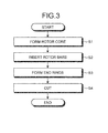
- FIG. 3 is a flowchart illustrating a manufacturing method of the squirrel-cage rotor 1 according to an embodiment of the present invention.
- step S1 stacking plates having the shaft hole 6 are stacked to form the rotor core 2
- the stacking plates are formed with not only the shaft hole 6 but also holes for the multiple slots 7, and accordingly, the stacking plates are stacked while aligning the positions of the holes for the shaft hole 6 and the slots 7.
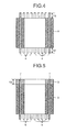
- FIGS. 4 to 6 are cross sectional views illustrating a step of manufacturing the squirrel-cage rotor 1. As illustrated in FIG. 4 , in this case, the length by which the rotor bar 5 projects out of the rotor core 2 is uniformly set as a predetermined length h2.
- the metal powder material of the end rings 3 and 4 is cold-sprayed to the end portions of the rotor core 2, so that the end rings 3 and 4 are formed (step S3).
- the material of the end ring 3 is cold-sprayed, and the end ring 3 is stacked and formed, and thereafter, the rotor core 2 is made in the opposite and fixed, and the shaft hole 6 is masked (not illustrated), and as illustrated in FIG. 6 , at the other end portion of the rotor core 2, the material of the end ring 4 is cold-sprayed, so that the end ring 4 is formed.
- FIG. 7 is an explanatory diagram illustrating overview of a thermal spraying device used to manufacture the squirrel-cage rotor 1 according to an embodiment of the present invention.
- the thermal spraying device 50 includes a gas heating device 40 for heating compressed gas, a powder providing device 41 for containing powder material thermally sprayed onto an object and providing a spray gun 44, and a gas nozzle 45 for injecting material powder mixed with compressed gas heated by the spray gun 44 to a base material.
- Helium, nitrogen, air, and the like are used as the compressed gas.
- the provided compressed gas is provided to the gas heating device 40 and the powder providing device 41 with valves 42 and 43, and the compressed gas provided to the gas heating device 40 is heated to, e.g., 50 to 700 degrees Celsius, and thereafter, the compressed gas is provided to the spray gun 44.
- the compressed gas is heated so that the maximum temperature of the spray material powder sprayed onto the base material is maintained at a level equal to or less than the melting point of the metal material. This is because, when the heating temperature of the powder material is maintained at a level equal to or less than the melting point of the metal material, oxidization of the metal material can be suppressed.
- the compressed gas provided to the powder providing device 41 is provided so that, e.g., the material powder of which particle diameter is about 10 to 100 ⁇ m in the powder providing device 41 is provided to the spray gun 44 with a predetermined amount of spray.
- the heated compressed gas is at a supersonic flow (about 340 m/s or more) by the gas nozzle 45 in a tapered shape.
- the powder material provided to the spray gun 44 is accelerated when the compressed gas is placed into the supersonic flow, and it collides with the base material at a high speed still in the solid state, so that a cover film is formed.
- any device capable of forming the cover film by causing the material powder to collide with the base material in the solid state can be used to manufacture the squirrel-cage rotor 1 according to an embodiment of the present invention, and is not limited to the thermal spraying device 50 of FIG. 7 .
- the end rings 3 and 4 are stacked and formed on the entire end surface perpendicular to the axial direction of the rotor core 2, but as long as they have the structure of short-circuiting and connecting all the rotor bars 5, the external diameter of the end rings 3 and 4 may be formed to be less than the external diameter of the rotor core 2, or the internal diameter of the end rings 3 and 4 may be formed to be more than the internal diameter of the rotor core 2.
- step S4 the upper surface, the external peripheral surface, and the internal peripheral surface of the stacked and formed end rings 3 and 4 are finished into a predetermined shape by cutting, grinding, and the like.
- the height of the end rings 3 and 4 is h1 in the ultimate shape
- the height h2 by which the rotor bar 5 projects out of the rotor core 2 is set as a length longer than h1.
- the end ring 3 and end ring 4 that short-circuit and connect the rotor bars 5 are formed by cold spray method, the used material is hardly oxidized, and the quality thereof hardly changes with heat, and the fine end rings with a high degree of contact strength can be formed.
- the end ring 3 and end ring 4 and the rotor bar 5 are bonded with the cold spray method, it takes much less time to bond them as compared with welding or brazing. Further, this can solve reduction of the strength and electrical failure that occurs due to the heat and sink marks made during welding and brazing, and moreover, there is an effect of solving casting failure that occurs due to, e.g., air inclusion and internal gases during casting.
- the squirrel-cage rotor having the rotor bars and the end rings made of the copper or the copper alloy can be manufactured in a short time without reducing the strength that occurs during bonding and the casting failure.
- the rotor bars and the end rings are made of the same material, but the end rings may be formed by the cold spray method, and different materials may be used.
- the material constituting the end rings can be selected without any limitation such as bonding, and the squirrel-cage rotor can be manufactured.
- FIG. 8 is a perspective view illustrating a configuration of the squirrel-cage rotor 1A according to a first modification of an embodiment of the present invention.
- FIG. 9 is a longitudinal cross-sectional view illustrating the squirrel-cage rotor 1 of FIG. 8 .
- rotor bars 5A are not exposed on the upper surfaces of end rings 3A and 4A.
- the rotor bar 5A inserted into the slot is configured to have a length h3, at which the rotor bar 5 slightly protrudes from the rotor core 2.
- the length h3 is preferably shorter as long as they are short-circuited and brought into conduction by the end rings 3A and 4A thereafter stacked and formed by the cold spray method.
- the rotor core 2 is formed by stacking the stacking plates having the shaft hole 6, and the rotor bars 5A formed with a predetermined material in a predetermined shape in advance are inserted into all the slots 7. Subsequently, the portion of the shaft hole 6 is masked, and the metal powder material of the end ring 3A is cold-sprayed from the upper side of the rotor bars 5A using the thermal spraying device 50 as illustrated in FIG. 7 , so that the end ring 3A is formed.
- the end ring 3A is formed by cold-spraying from the above without masking the portions of the rotor bars 5A, and the end ring 3A can be formed more easily.
- the end ring 4A is formed in the same manner, and the upper surface, the external peripheral surface, and internal peripheral surface of the end rings 3A and 4A stacked formed are made into a predetermined shape by, e.g., cutting and grinding, so that the squirrel-cage rotor 1A is formed.
- the squirrel-cage rotor 1A according to the first modification is made by bonding the end ring 3A and the end ring 4A with the rotor bars 5A by the cold spray method, and therefore, it takes much less time to bond them as compared with welding and brazing. Further, this can solve reduction of the strength and electrical failure that occurs due to the heat and sink marks made during welding and brazing, and moreover, there is an effect of solving casting failure that occurs due to, e.g., air inclusion and internal gases during casting. According to this first modification, the configuration of the mask portion during cold spray is easy, and therefore, the end rings 3A and 4A can be formed more easily.
- the present invention can be used for a squirrel-cage rotor and a manufacturing method thereof, and in particular, the present invention is useful for a high-speed squirrel-cage rotor.
Landscapes
- Engineering & Computer Science (AREA)
- Power Engineering (AREA)
- Manufacturing & Machinery (AREA)
- Induction Machinery (AREA)
- Manufacture Of Motors, Generators (AREA)
Abstract
Description
- The present invention relates to a squirrel-cage rotor and a manufacturing method of a squirrel-cage rotor. Background
- Conventionally a technique for fixing a rotor core to a mold, filling the mold with molten metal which is a material for a rotor bar and an end ring, and integrally forming the rotor bar and the end ring with casting is known as a technique for manufacturing a squirrel-cage rotor (see Patent Literature 1). A technique for inserting many rotor bars to the rotor core and thereafter manufacturing the rotor bars and end rings by welding the rotor bars and the end rings or brazing the rotor bars and the end rings is also known as a technique for manufacturing a squirrel-cage rotor (see
Patent Literature 2 or 3). - Patent Literature 1: Japanese Patent Laid-open No.
2005-12907
Patent Literature 2: Japanese Patent Laid-open No.2007-202235
Patent Literature 3: Japanese Patent Laid-open No.2002-335659 - However, when a rotor is manufactured with casting as described in
Patent Literature 1, casting failure may occur due to, e.g., air inclusion and internal gases during the casting. - As described in
Patent Literature - The present invention is made in view of the above problem, and it is an object of the present invention to provide a squirrel-cage rotor and a manufacturing method of a squirrel-cage rotor capable of preventing occurrence of, e.g., internal defect and reduction of strength and reducing the time it takes to manufacture the squirrel-cage rotor.
- To solve the problem described above and achieve the object, a squirrel-cage rotor according to the present invention includes: a rotor core made by stacking a plurality of cores made of steel plates and having a plurality of slots extending in parallel to each other; a plurality of rotor bars respectively inserted into the plurality of slots, the rotor bars being made of metal and having lengths longer than the lengths of the slots inserted; and two end rings respectively provided at end portions of the rotor core and both end portions in a direction in which the plurality of slots extend, the two end rings short-circuiting the plurality of rotor bars, wherein the end rings are formed by blowing, to the end portions, metal material powder in a solid state constituting the end rings at a temperature lower than a melting point of the metal material powder using heated compressed gas.
- In the squirrel-cage rotor according to the present invention as set forth in the invention described above, the end portions of the plurality of rotor bars are buried in an inside of the end rings.
- In the squirrel-cage rotor according to the present invention as set forth in the invention described above, the end rings are made of aluminum, aluminum alloy, copper, or copper alloy.
- In the squirrel-cage rotor according to the present invention as set forth in the invention described above, the end rings are made of copper or copper alloy including alumina, tungsten, or zirconium as a dispersion material.
- In a manufacturing method of a squirrel-cage rotor including a rotor core made by stacking a plurality of cores made of steel plates and having a plurality of slots extending in parallel to each other, a plurality of rotor bars respectively inserted into the plurality of slots, the rotor bars being made of metal and having lengths longer than the lengths of the slots inserted, and two end rings respectively provided at end portions of the rotor core and both end portions in a direction in which the plurality of slots extend, the two end rings short-circuiting the plurality of rotor bars according to the present invention, the end rings are formed by blowing, to the end portions, metal material powder in a solid state constituting the end rings at a temperature lower than a melting point of the metal material powder using heated compressed gas.
- In the squirrel-cage rotor according to the present invention as set forth in the invention described above, the end rings are formed by blowing, to the end portions of the rotor core, the metal material powder in the solid state constituting the end rings at a temperature lower than the melting point of the metal material powder using heated compressed gas, so that the end portions of the plurality of rotor bars are buried.
- In the squirrel-cage rotor according to the present invention, an end ring is formed by blowing mental material powder in a solid state constituting the end ring to an end portion of the rotor core at a temperature lower than a melting point of the metal material powder using a heated compressed gas, so that there is an advantage in that the squirrel-cage rotor according to the present invention can be manufactured in a short time without causing internal defect and reduction of the strength due to heat generated during bonding.
-
-
FIG. 1 is a perspective view illustrating a configuration of a squirrel-cage rotor according to an embodiment of the present invention. -
FIG. 2 is a longitudinal cross-sectional view illustrating the squirrel-cage rotor ofFIG. 1 . -
FIG. 3 is a flowchart illustrating a manufacturing method of the squirrel-cage rotor according to an embodiment of the present invention. -
FIG. 4 is a cross sectional view illustrating a step of manufacturing the squirrel-cage rotor according to an embodiment of the present invention. -
Fig. 5 is cross sectional view illustrating a step of manufacturing the squirrel-cage rotor according to an embodiment of the present invention. -
FIG. 6 is a cross sectional view illustrating a step of manufacturing the squirrel-cage rotor according to an embodiment of the present invention. -
FIG. 7 is an explanatory diagram illustrating overview of a thermal spraying device used to manufacture the squirrel-cage rotor according to an embodiment of the present invention. -
FIG. 8 is a perspective view illustrating a configuration of the squirrel-cage rotor according to a modification of the present invention. -
FIG. 9 is a longitudinal cross-sectional view illustrating a squirrel-cage rotor ofFIG. 8 . - Hereinafter, an embodiment of a squirrel-cage rotor according to the present invention will be explained in detail with reference to drawings. It should be noted that the present invention is not limited to the embodiment, and can be changed in various manners without deviating from the gist of the present invention.
-
FIG. 1 is a perspective view illustrating a configuration of a squirrel-cage rotor 1 according to an embodiment of the present invention.FIG. 2 is a longitudinal cross-sectional view illustrating the squirrel-cage rotor 1 ofFIG. 1 . The squirrel-cage rotor 1 includes arotor core 2,rotor bars 5, andend rings - The
rotor core 2 is made of stacked plates made of silicon steel plate in a hollow disk shape having ashaft hole 6 at a central portion into which a rotation shaft is inserted. Around theshaft hole 6 of therotor core 2,multiple slots 7 into which therotor bars 5 are inserted are arranged in a peripheral direction. - The
rotor bar 5 is a long and narrow rod-shaped body in a circular column shape, in a square column shape, or in a rectangular column shape. Therotor bar 5 is formed by cutting or casting a metal having a high electrical conductivity such as aluminum, aluminum alloy, copper, copper alloy, gold, silver, or platinum. When the squirrel-cage rotor 1 is used for the purpose of a high number of revolutions, a large amount of current is passed through therotor bars 5. Therefore, the material used for therotor bar 5 is selected in view of electrical resistance value or mechanical strength. For example, the squirrel-cage rotor 1 for a high number of revolutions mainly uses copper or copper alloy of which electrical resistance is low and of which mechanical strength is high. When therotor bar 5 is formed of a metallic material having a dispersion material added thereto in accordance with the purpose of use of the squirrel-cage rotor 1, the strength and the thermal expansion rate of therotor bar 5 can be adjusted. One weight percent of alumina, tungsten, zirconium, and the like is used as the dispersion material for the copper or the copper alloy. Silicon carbide and the like are used as the dispersion material for aluminum or aluminum alloy. - According to an embodiment of the present invention, the
rotor bars 5 are formed by cutting and the like in advance, and thereafter, therotor bars 5 are inserted into theslots 7, but when, e.g., the length of theslot 7 is short (the length of therotor core 2 is short), therotor bars 5 may be formed by directly stacking material powder of therotor bars 5 in theslots 7, using cold spray method, explained later. - The
end rings rotor bars 5 inserted into theslots 7 of therotor core 2. Like therotor bar 5, theend rings end rings rotor bars 5 at a temperature lower than the melting point of the metal material powder using heated compressed gas. How theend rings - When the squirrel-
cage rotor 1 is used for the purpose of a high number of revolutions, a large amount of current is passed through theend rings end rings cage rotor 1 for a high number of revolutions mainly uses copper or copper alloy of which electrical resistance is low and of which mechanical strength is high. When theend rings cage rotor 1, the strength and the thermal expansion rate of theend rings - Subsequently, a manufacturing method of the squirrel-
cage rotor 1 according to an embodiment of the present invention will be explained with reference toFIGS. 3 to 7 .FIG. 3 is a flowchart illustrating a manufacturing method of the squirrel-cage rotor 1 according to an embodiment of the present invention. - As illustrated in the flowchart of
FIG. 3 , first, stacking plates having theshaft hole 6 are stacked to form the rotor core 2 (step S1). The stacking plates are formed with not only theshaft hole 6 but also holes for themultiple slots 7, and accordingly, the stacking plates are stacked while aligning the positions of the holes for theshaft hole 6 and theslots 7. - Subsequently, the
rotor bars 5 formed with a predetermined material in a predetermined shape in advance are inserted into all the slots 7 (step S2).FIGS. 4 to 6 are cross sectional views illustrating a step of manufacturing the squirrel-cage rotor 1. As illustrated inFIG. 4 , in this case, the length by which therotor bar 5 projects out of therotor core 2 is uniformly set as a predetermined length h2. - Thereafter, after the
shaft hole 6 is masked (not illustrated), the metal powder material of the end rings 3 and 4 is cold-sprayed to the end portions of therotor core 2, so that the end rings 3 and 4 are formed (step S3). At one of the end portions of therotor core 2, for example, as illustrated inFIG. 5 , the material of theend ring 3 is cold-sprayed, and theend ring 3 is stacked and formed, and thereafter, therotor core 2 is made in the opposite and fixed, and theshaft hole 6 is masked (not illustrated), and as illustrated inFIG. 6 , at the other end portion of therotor core 2, the material of theend ring 4 is cold-sprayed, so that theend ring 4 is formed. - The cold spray is performed using a
thermal spraying device 50 as illustrated inFIG. 7. FIG. 7 is an explanatory diagram illustrating overview of a thermal spraying device used to manufacture the squirrel-cage rotor 1 according to an embodiment of the present invention. Thethermal spraying device 50 includes agas heating device 40 for heating compressed gas, apowder providing device 41 for containing powder material thermally sprayed onto an object and providing aspray gun 44, and agas nozzle 45 for injecting material powder mixed with compressed gas heated by thespray gun 44 to a base material. - Helium, nitrogen, air, and the like are used as the compressed gas. The provided compressed gas is provided to the
gas heating device 40 and thepowder providing device 41 withvalves gas heating device 40 is heated to, e.g., 50 to 700 degrees Celsius, and thereafter, the compressed gas is provided to thespray gun 44. Preferably, the compressed gas is heated so that the maximum temperature of the spray material powder sprayed onto the base material is maintained at a level equal to or less than the melting point of the metal material. This is because, when the heating temperature of the powder material is maintained at a level equal to or less than the melting point of the metal material, oxidization of the metal material can be suppressed. The compressed gas provided to thepowder providing device 41 is provided so that, e.g., the material powder of which particle diameter is about 10 to 100 µm in thepowder providing device 41 is provided to thespray gun 44 with a predetermined amount of spray. The heated compressed gas is at a supersonic flow (about 340 m/s or more) by thegas nozzle 45 in a tapered shape. The powder material provided to thespray gun 44 is accelerated when the compressed gas is placed into the supersonic flow, and it collides with the base material at a high speed still in the solid state, so that a cover film is formed. Any device capable of forming the cover film by causing the material powder to collide with the base material in the solid state can be used to manufacture the squirrel-cage rotor 1 according to an embodiment of the present invention, and is not limited to thethermal spraying device 50 ofFIG. 7 . - According to an embodiment of the present invention, the end rings 3 and 4 are stacked and formed on the entire end surface perpendicular to the axial direction of the
rotor core 2, but as long as they have the structure of short-circuiting and connecting all the rotor bars 5, the external diameter of the end rings 3 and 4 may be formed to be less than the external diameter of therotor core 2, or the internal diameter of the end rings 3 and 4 may be formed to be more than the internal diameter of therotor core 2. - Subsequently, the upper surface, the external peripheral surface, and the internal peripheral surface of the stacked and formed end rings 3 and 4 are finished into a predetermined shape by cutting, grinding, and the like (step S4). When the height of the end rings 3 and 4 is h1 in the ultimate shape, the height h2 by which the
rotor bar 5 projects out of therotor core 2 is set as a length longer than h1. - As described above, when the
end ring 3 and endring 4 that short-circuit and connect the rotor bars 5 are formed by cold spray method, the used material is hardly oxidized, and the quality thereof hardly changes with heat, and the fine end rings with a high degree of contact strength can be formed. When theend ring 3 and endring 4 and therotor bar 5 are bonded with the cold spray method, it takes much less time to bond them as compared with welding or brazing. Further, this can solve reduction of the strength and electrical failure that occurs due to the heat and sink marks made during welding and brazing, and moreover, there is an effect of solving casting failure that occurs due to, e.g., air inclusion and internal gases during casting. - In recent years, high-speed rotation rotors using copper or copper alloy for the rotor bars and the end rings are manufactured, but the copper or the copper alloy have high melting points, and therefore, it is difficult to integrally form the rotor bars and end rings with casting. According to the present invention, the squirrel-cage rotor having the rotor bars and the end rings made of the copper or the copper alloy can be manufactured in a short time without reducing the strength that occurs during bonding and the casting failure.
- Further, conventionally, when a squirrel-cage rotor is manufactured according to an assembly method by casting, welding, or brazing, the rotor bars and the end rings are made of the same material, but the end rings may be formed by the cold spray method, and different materials may be used. In this case, the material constituting the end rings can be selected without any limitation such as bonding, and the squirrel-cage rotor can be manufactured.
- A squirrel-
cage rotor 1A as illustrated inFIG. 8 is illustrated as an example of a squirrel-cage rotor according to a modification of an embodiment of the present invention.FIG. 8 is a perspective view illustrating a configuration of the squirrel-cage rotor 1A according to a first modification of an embodiment of the present invention.FIG. 9 is a longitudinal cross-sectional view illustrating the squirrel-cage rotor 1 ofFIG. 8 . In the squirrel-cage rotor 1A, rotor bars 5A are not exposed on the upper surfaces of end rings 3A and 4A. - As illustrated in
FIG. 9 , therotor bar 5A inserted into the slot is configured to have a length h3, at which therotor bar 5 slightly protrudes from therotor core 2. The length h3 is preferably shorter as long as they are short-circuited and brought into conduction by the end rings 3A and 4A thereafter stacked and formed by the cold spray method. - When the squirrel-
cage rotor 1A according to the first modification is manufactured, therotor core 2 is formed by stacking the stacking plates having theshaft hole 6, and the rotor bars 5A formed with a predetermined material in a predetermined shape in advance are inserted into all theslots 7. Subsequently, the portion of theshaft hole 6 is masked, and the metal powder material of theend ring 3A is cold-sprayed from the upper side of the rotor bars 5A using thethermal spraying device 50 as illustrated inFIG. 7 , so that theend ring 3A is formed. Theend ring 3A is formed by cold-spraying from the above without masking the portions of the rotor bars 5A, and theend ring 3A can be formed more easily. Theend ring 4A is formed in the same manner, and the upper surface, the external peripheral surface, and internal peripheral surface of the end rings 3A and 4A stacked formed are made into a predetermined shape by, e.g., cutting and grinding, so that the squirrel-cage rotor 1A is formed. - Like the squirrel-cage rotor according to an embodiment of the present invention, the squirrel-
cage rotor 1A according to the first modification is made by bonding theend ring 3A and theend ring 4A with the rotor bars 5A by the cold spray method, and therefore, it takes much less time to bond them as compared with welding and brazing. Further, this can solve reduction of the strength and electrical failure that occurs due to the heat and sink marks made during welding and brazing, and moreover, there is an effect of solving casting failure that occurs due to, e.g., air inclusion and internal gases during casting. According to this first modification, the configuration of the mask portion during cold spray is easy, and therefore, the end rings 3A and 4A can be formed more easily. - The present invention can be used for a squirrel-cage rotor and a manufacturing method thereof, and in particular, the present invention is useful for a high-speed squirrel-cage rotor.
-
1, 1A squirrel- cage rotor 2 rotor core 3, 3A, 4, 4A end ring 5, 5A rotor bar 6 shaft hole 7 slot 40 gas heating device 41 powder providing device 42, 43 valve 44 spray gun 45 gas nozzle 50 thermal spraying device
Claims (6)
- A squirrel-cage rotor comprising:a rotor core made by stacking a plurality of cores made of steel plates and having a plurality of slots extending in parallel to each other;a plurality of rotor bars respectively inserted into the plurality of slots, the rotor bars being made of metal and having lengths longer than the lengths of the slots inserted; andtwo end rings respectively provided at end portions of the rotor core and both end portions in a direction in which the plurality of slots extend, the two end rings short-circuiting the plurality of rotor bars,wherein the end rings are formed by blowing, to the end portions, metal material powder in a solid state constituting the end rings at a temperature lower than a melting point of the metal material powder using heated compressed gas.
- The squirrel-cage rotor according to claim 1, wherein the end portions of the plurality of rotor bars are buried in an inside of the end rings.
- The squirrel-cage rotor according to claim 1 or 2, wherein the end rings are made of aluminum, aluminum alloy, copper, or copper alloy.
- The squirrel-cage rotor according to claim 3, wherein the end rings are made of copper or copper alloy including alumina, tungsten, or zirconium as a dispersion material.
- A manufacturing method for a squirrel-cage rotor comprising a rotor core made by stacking a plurality of cores made of steel plates and having a plurality of slots extending in parallel to each other, a plurality of rotor bars respectively inserted into the plurality of slots, the rotor bars being made of metal and having lengths longer than the lengths of the slots inserted, and two end rings respectively provided at end portions of the rotor core and both end portions in a direction in which the plurality of slots extend, the two end rings short-circuiting the plurality of rotor bars,
wherein the end rings are formed by blowing, to the end portions, metal material powder in a solid state constituting the end rings at a temperature lower than a melting point of the metal material powder using heated compressed gas. - The manufacturing method for the squirrel-cage rotor according to claim 5, wherein the end rings are formed by blowing, to the end portions of the rotor core, the metal material powder in the solid state constituting the end rings at a temperature lower than the melting point of the metal material powder using heated compressed gas, so that the end portions of the plurality of rotor bars are buried.
Applications Claiming Priority (2)
| Application Number | Priority Date | Filing Date | Title |
|---|---|---|---|
| JP2010156068A JP5693884B2 (en) | 2010-07-08 | 2010-07-08 | Cage type rotor and method of manufacturing a cage type rotor |
| PCT/JP2011/065506 WO2012005304A1 (en) | 2010-07-08 | 2011-07-06 | Cage rotor, and cage rotor manufacturing method |
Publications (2)
| Publication Number | Publication Date |
|---|---|
| EP2592730A1 true EP2592730A1 (en) | 2013-05-15 |
| EP2592730A4 EP2592730A4 (en) | 2017-06-28 |
Family
ID=45441280
Family Applications (1)
| Application Number | Title | Priority Date | Filing Date |
|---|---|---|---|
| EP11803638.3A Withdrawn EP2592730A4 (en) | 2010-07-08 | 2011-07-06 | Cage rotor, and cage rotor manufacturing method |
Country Status (4)
| Country | Link |
|---|---|
| US (1) | US20130106233A1 (en) |
| EP (1) | EP2592730A4 (en) |
| JP (1) | JP5693884B2 (en) |
| WO (1) | WO2012005304A1 (en) |
Cited By (2)
| Publication number | Priority date | Publication date | Assignee | Title |
|---|---|---|---|---|
| EP3595146A1 (en) * | 2018-07-12 | 2020-01-15 | Siemens Aktiengesellschaft | Rotor having a short circuit cage, method of manufacturing |
| EP3629452A1 (en) * | 2018-09-28 | 2020-04-01 | Siemens Aktiengesellschaft | Method for the preparation of a rotor of a rotary electric machine |
Families Citing this family (11)
| Publication number | Priority date | Publication date | Assignee | Title |
|---|---|---|---|---|
| JP5155423B2 (en) * | 2011-04-04 | 2013-03-06 | ファナック株式会社 | Cage-shaped rotor and manufacturing method thereof |
| JP5326012B2 (en) | 2012-02-14 | 2013-10-30 | ファナック株式会社 | Rotor with cage-shaped conductor formed with reinforcing structure and method for manufacturing the same |
| KR101545785B1 (en) * | 2013-11-07 | 2015-08-19 | (주) 에이스터보 | Rotor for squirrel cage induction motor |
| JP2015162913A (en) * | 2014-02-26 | 2015-09-07 | 住友重機械工業株式会社 | Induction motor and manufacturing method of rotor thereof |
| WO2015151244A1 (en) * | 2014-04-02 | 2015-10-08 | 三菱電機株式会社 | Squirrel-cage rotor |
| KR101696043B1 (en) * | 2014-12-22 | 2017-01-13 | 주식회사 포스코 | Manufacturing apparatus and method for rotor of motor |
| DE102017207671A1 (en) * | 2017-05-08 | 2018-11-08 | Audi Ag | Rotor for an electric machine, electric machine comprising such a rotor and method for producing a rotor |
| CN108110922A (en) * | 2017-10-17 | 2018-06-01 | 晟昌机电股份有限公司 | Motor rotor short circuit ring and conductive copper sheet combination method |
| CN113241910A (en) * | 2021-06-08 | 2021-08-10 | 苏州精力电气有限公司 | Preparation method of low-loss squirrel-cage motor rotor |
| DE102023103204A1 (en) * | 2023-02-09 | 2024-08-14 | Additive | Drives GmbH | Method for producing a rotor and/or runner and/or rotor and electrical machine |
| FR3147060A1 (en) * | 2023-03-23 | 2024-09-27 | Safran Ventilation Systems | METHOD FOR MANUFACTURING A SQUIRREL CAGE ROTOR FOR AN ELECTRIC MACHINE |
Family Cites Families (19)
| Publication number | Priority date | Publication date | Assignee | Title |
|---|---|---|---|---|
| US1160428A (en) * | 1912-11-14 | 1915-11-16 | George E Markley | Art of metal-working. |
| JPS5454209A (en) * | 1977-10-07 | 1979-04-28 | Toshiba Corp | Method of manufacturing aluminum casting rotor of revolving electric machine |
| DE3031159A1 (en) * | 1979-08-14 | 1982-04-01 | Siemens AG, 1000 Berlin und 8000 München | Short-circuit rotor cage for electrical machine - uses short-circuit bars with transverse bore or keying indentation at each end |
| DE2932952A1 (en) * | 1979-08-14 | 1981-03-26 | Siemens AG, 1000 Berlin und 8000 München | METHOD FOR PRODUCING SHORT CIRCUIT CABLES |
| JPH02193552A (en) * | 1989-01-18 | 1990-07-31 | Toshiba Heating Appliances Co | Manufacture of rotor for motor |
| JPH02219444A (en) * | 1989-02-17 | 1990-09-03 | Mitsubishi Electric Corp | Manufacture of cage rotor |
| US5185918A (en) * | 1991-10-25 | 1993-02-16 | General Motors Corporation | Method of manufacturing a copper bar induction rotor |
| JPH05260710A (en) * | 1992-03-16 | 1993-10-08 | Toshiba Corp | Manufacture of squirrel-cage rotor |
| DE4308683A1 (en) * | 1993-03-18 | 1994-09-22 | Siemens Ag | Squirrel-cage rotor for an asynchronous machine |
| JPH09117119A (en) * | 1995-10-17 | 1997-05-02 | Toshiba Corp | Cage-shaped rotor and manufacturing method thereof |
| JP2000060079A (en) * | 1998-08-07 | 2000-02-25 | Matsushita Electric Ind Co Ltd | Rotor manufacturing method |
| JP4560755B2 (en) * | 2000-11-02 | 2010-10-13 | 株式会社Ihi | Induction motor rotor manufacturing method |
| JP2002335659A (en) * | 2001-05-09 | 2002-11-22 | Yaskawa Electric Corp | Cage rotor and its manufacturing method. |
| US6592935B2 (en) * | 2001-05-30 | 2003-07-15 | Ford Motor Company | Method of manufacturing electromagnetic devices using kinetic spray |
| JP2003230261A (en) * | 2002-01-31 | 2003-08-15 | Ishikawajima Harima Heavy Ind Co Ltd | Induction machine rotor structure and rotor manufacturing method |
| JP4245988B2 (en) | 2003-06-18 | 2009-04-02 | 三菱電機株式会社 | Manufacturing apparatus and manufacturing method for cage rotor |
| JP2005333743A (en) * | 2004-05-20 | 2005-12-02 | Yaskawa Electric Corp | Cage type rotor and manufacturing method thereof |
| JP2006052449A (en) * | 2004-08-13 | 2006-02-23 | Nippon Steel Corp | Method for forming a cold spray film |
| JP4868122B2 (en) | 2006-01-24 | 2012-02-01 | 株式会社安川電機 | Cage type rotor and electric motor using the same |
-
2010
- 2010-07-08 JP JP2010156068A patent/JP5693884B2/en active Active
-
2011
- 2011-07-06 EP EP11803638.3A patent/EP2592730A4/en not_active Withdrawn
- 2011-07-06 WO PCT/JP2011/065506 patent/WO2012005304A1/en not_active Ceased
- 2011-07-06 US US13/807,856 patent/US20130106233A1/en not_active Abandoned
Non-Patent Citations (1)
| Title |
|---|
| See references of WO2012005304A1 * |
Cited By (4)
| Publication number | Priority date | Publication date | Assignee | Title |
|---|---|---|---|---|
| EP3595146A1 (en) * | 2018-07-12 | 2020-01-15 | Siemens Aktiengesellschaft | Rotor having a short circuit cage, method of manufacturing |
| EP3629452A1 (en) * | 2018-09-28 | 2020-04-01 | Siemens Aktiengesellschaft | Method for the preparation of a rotor of a rotary electric machine |
| WO2020064413A1 (en) * | 2018-09-28 | 2020-04-02 | Siemens Aktiengesellschaft | Method for producing a rotor for an electric rotating machine |
| US11411475B2 (en) | 2018-09-28 | 2022-08-09 | Siemens Aktiengesellschaft | Method for producing a rotor for an electric rotating machine |
Also Published As
| Publication number | Publication date |
|---|---|
| JP2012019634A (en) | 2012-01-26 |
| WO2012005304A1 (en) | 2012-01-12 |
| US20130106233A1 (en) | 2013-05-02 |
| EP2592730A4 (en) | 2017-06-28 |
| JP5693884B2 (en) | 2015-04-01 |
Similar Documents
| Publication | Publication Date | Title |
|---|---|---|
| US20130106233A1 (en) | Squirrel-cage rotor and manufacturing method of squirrel-cage rotor | |
| CN102738988B (en) | Squirrel-cage rotor and production method thereof | |
| JP4728419B2 (en) | Cage type rotor and method of manufacturing a cage type rotor | |
| JP5993144B2 (en) | Cooling channel system and associated method for high temperature components covered by a coating | |
| CA2958128C (en) | Casting with metal components and metal skin layers | |
| US20160010469A1 (en) | Hybrid manufacturing for rotors | |
| EP2662473A1 (en) | Conductive member | |
| EP3369937B1 (en) | Method of manufacturing impeller | |
| US20160208645A1 (en) | Blade outer air seal cooling scheme | |
| CN103795195A (en) | Induction rotor and method for fabricating the same | |
| CN111869061A (en) | Method for making squirrel cage rotors | |
| EP2920868B1 (en) | Casting technology for induction rotor assemblies | |
| EP3210693A1 (en) | Casting with a second metal component formed around a first metal component using hot isostatic pressing | |
| EP4227022A1 (en) | Bulk dual phase soft magnetic components having three-dimensional magnetic flux and manufacturing methods | |
| JP5571472B2 (en) | Heater unit with shaft and heater unit manufacturing method with shaft | |
| US9713838B2 (en) | Static core tie rods | |
| JP2008522582A (en) | Cryogenic pump system, rotor, and method of pumping cryogenic fluid | |
| CN113828954B (en) | Metal-ceramic sealing method, metal-ceramic composite structure | |
| KR101098303B1 (en) | Rotor of induction motor and its manufacturing method | |
| JP4480438B2 (en) | Electronic component manufacturing method | |
| JP2026507042A (en) | Three-dimensional magnetic flux motor and its manufacturing method | |
| RU2361307C2 (en) | Smelted magnetic medium on basis of hard-magnetic alloy and method of manufacturing from it of monolithic magnetic circuits of electric machines | |
| JP6576449B2 (en) | Charging equipment for heat treatment of tantalum capacitors | |
| JP2018103233A (en) | Composite metal wire and manufacturing method thereof | |
| KR20090102389A (en) | Duct spacer and diecast roter manufacturing method having cooling passage used thereof |
Legal Events
| Date | Code | Title | Description |
|---|---|---|---|
| PUAI | Public reference made under article 153(3) epc to a published international application that has entered the european phase |
Free format text: ORIGINAL CODE: 0009012 |
|
| 17P | Request for examination filed |
Effective date: 20130103 |
|
| AK | Designated contracting states |
Kind code of ref document: A1 Designated state(s): AL AT BE BG CH CY CZ DE DK EE ES FI FR GB GR HR HU IE IS IT LI LT LU LV MC MK MT NL NO PL PT RO RS SE SI SK SM TR |
|
| DAX | Request for extension of the european patent (deleted) | ||
| RA4 | Supplementary search report drawn up and despatched (corrected) |
Effective date: 20170529 |
|
| RIC1 | Information provided on ipc code assigned before grant |
Ipc: H02K 17/16 20060101AFI20170522BHEP Ipc: H02K 15/02 20060101ALI20170522BHEP |
|
| 17Q | First examination report despatched |
Effective date: 20180410 |
|
| STAA | Information on the status of an ep patent application or granted ep patent |
Free format text: STATUS: THE APPLICATION IS DEEMED TO BE WITHDRAWN |
|
| 18D | Application deemed to be withdrawn |
Effective date: 20180821 |