EP2592424A1 - Automatic analyzer - Google Patents
Automatic analyzer Download PDFInfo
- Publication number
- EP2592424A1 EP2592424A1 EP11803502.1A EP11803502A EP2592424A1 EP 2592424 A1 EP2592424 A1 EP 2592424A1 EP 11803502 A EP11803502 A EP 11803502A EP 2592424 A1 EP2592424 A1 EP 2592424A1
- Authority
- EP
- European Patent Office
- Prior art keywords
- reagent
- automatic analyzer
- transfer mechanism
- dispensing probe
- reagent container
- Prior art date
- Legal status (The legal status is an assumption and is not a legal conclusion. Google has not performed a legal analysis and makes no representation as to the accuracy of the status listed.)
- Granted
Links
Images



Classifications
-
- G—PHYSICS
- G01—MEASURING; TESTING
- G01N—INVESTIGATING OR ANALYSING MATERIALS BY DETERMINING THEIR CHEMICAL OR PHYSICAL PROPERTIES
- G01N35/00—Automatic analysis not limited to methods or materials provided for in any single one of groups G01N1/00 - G01N33/00; Handling materials therefor
- G01N35/10—Devices for transferring samples or any liquids to, in, or from, the analysis apparatus, e.g. suction devices, injection devices
- G01N35/1065—Multiple transfer devices
-
- G—PHYSICS
- G01—MEASURING; TESTING
- G01N—INVESTIGATING OR ANALYSING MATERIALS BY DETERMINING THEIR CHEMICAL OR PHYSICAL PROPERTIES
- G01N35/00—Automatic analysis not limited to methods or materials provided for in any single one of groups G01N1/00 - G01N33/00; Handling materials therefor
- G01N35/02—Automatic analysis not limited to methods or materials provided for in any single one of groups G01N1/00 - G01N33/00; Handling materials therefor using a plurality of sample containers moved by a conveyor system past one or more treatment or analysis stations
- G01N35/04—Details of the conveyor system
-
- G—PHYSICS
- G01—MEASURING; TESTING
- G01N—INVESTIGATING OR ANALYSING MATERIALS BY DETERMINING THEIR CHEMICAL OR PHYSICAL PROPERTIES
- G01N35/00—Automatic analysis not limited to methods or materials provided for in any single one of groups G01N1/00 - G01N33/00; Handling materials therefor
- G01N35/02—Automatic analysis not limited to methods or materials provided for in any single one of groups G01N1/00 - G01N33/00; Handling materials therefor using a plurality of sample containers moved by a conveyor system past one or more treatment or analysis stations
- G01N35/04—Details of the conveyor system
- G01N2035/0474—Details of actuating means for conveyors or pipettes
- G01N2035/0491—Position sensing, encoding; closed-loop control
-
- G—PHYSICS
- G01—MEASURING; TESTING
- G01N—INVESTIGATING OR ANALYSING MATERIALS BY DETERMINING THEIR CHEMICAL OR PHYSICAL PROPERTIES
- G01N35/00—Automatic analysis not limited to methods or materials provided for in any single one of groups G01N1/00 - G01N33/00; Handling materials therefor
- G01N35/10—Devices for transferring samples or any liquids to, in, or from, the analysis apparatus, e.g. suction devices, injection devices
- G01N35/1009—Characterised by arrangements for controlling the aspiration or dispense of liquids
- G01N35/1011—Control of the position or alignment of the transfer device
Definitions
- This invention relates to an automatic analyzer for analyzing specimens of blood, urine or the like. More particularly, the invention relates to an automatic analyzer furnished with a mechanism for replacing reagent containers.
- Patent Document 1 discloses an automatic analyzer which includes replacement reagent storage means 2 apart from reagent storage means 1 in an analysis unit and which has reagent transport means interposed between the reagent storage means 1 and the replacement reagent storage means 2, thereby simplifying the work of reagent replacement and minimizing interruptions of analytical work.
- An object of this invention is to provide an automatic analyzer having a reagent transport mechanism for automatically replacing reagent containers, the reagent transport mechanism being moved at the same height as those of diverse units including the reagent probe so that the equipment size may be kept small and that the analyzer may operate without problems.
- the present invention may be configured as follows:
- An automatic analyzer including: a reagent container which contains a reagent; reagent container placement mechanisms which place a plurality of the reagent containers; a reagent dispensing probe with a mechanism for transferring the position of a nozzle which aspirates a predetermined amount of a reagent held in the reagent containers on the reagent container placement mechanisms, before discharging the aspirated reagent into a reaction container, and a reagent container transfer mechanism which transfers the reagent containers to the reagent container placement mechanisms.
- the reagent dispensing probe and the reagent container transfer mechanism are configured to interfere with one another.
- the automatic analyzer further includes: a position detection mechanism which detects the position of at least either the reagent dispensing probe or the reagent container transfer mechanism, and a control mechanism which, if the position detection mechanism detects that at least either the reagent dispensing probe or the reagent container transfer mechanism is in a predetermined position, performs control not to transfer at least either the reagent dispensing probe or the reagent container transfer mechanism.
- the automatic analyzer performs reset operations of various units for operation check thereof.
- the reagent transport mechanism should preferably be furnished with a detector, a detection plate, etc., as means for determining whether the reagent transport mechanism is in a non-resettable region.
- the detector and detection plate attached to the reagent transport mechanism permit the analyzer to detect the position of the reagent transport mechanism. This allows the reagent transport mechanism to transport reagent cassettes without interfering with the reagent probe.
- Fig. 1 is a plan view of the automatic analyzer.
- An automatic analyzer is made up of an analysis unit 10 and a buffer unit 11.
- the analysis unit 10 includes reagent cabinets A 28 and B 29, a reagent transport mechanism 27 that takes a reagent container 12 from the buffer unit 11 and transports the container to the reagent cabinet A 28 or B 29, and a reagent ejection and stowing mechanism 26 that ejects the reagent container 12 from the analysis unit 10.
- the buffer unit 11 includes a replenishing reagent cabinet 20 that temporarily stores replenishing reagents and a reagent ejection mechanism 25 that ejects the reagent containers.
- a reagent injection mechanism 24 transfers the reagent container 12 to the replenishing reagent cabinet 20.
- the reagent container 12 transferred to the replenishing reagent cabinet 20 carries an RFID tag on which is recorded such information as the remaining reagent amount, a lot number, and a use-by date.
- the information is read by a reagent information read mechanism 21 mounted on the replenishing reagent cabinet 20, and is stored into a control computer, not shown.
- the reagent container 12 is ejected by the reagent ejection mechanism 25 in the buffer unit 11 if the container in question is determined to be unusable for analysis by the control computer for such reasons as expiration of the use-by date or an insufficient remaining amount of the reagent.
- the reagent for which a reagent replenishment request has been issued is transferred to a cap opening position of a reagent cap opening mechanism 23 mounted beforehand on the replenishing reagent cabinet 20.
- the cap opening position the reagent cap of the reagent container 12 is opened, and the cap is discarded into a reagent cap disposal box 34.
- the reagent cassette 12 with its reagent cap opened is sent to a reagent container transfer position inside the replenishing reagent cabinet 20. Once placed in that position, the reagent cassette 12 is sent from the buffer unit 11 to the analysis unit 10 by a reagent container transfer mechanism 22.
- the replacing of reagents is timed to be performed typically in an idle cycle between exhausted reagents or an interval between the dispensing of a first reagent and that of a second reagent, provided the replacing will not cause a shortage of reagents. If the replenishment of a reagent cannot be completed in time, the sampling of specimens is suspended, the reagent is dispensed to the specimens yet to be sampled, and then the reagent is replenished. In any case, the equipment is currently in analyzing mode and not temporarily stopped to have the reagent replenished. Thus the idle time resulting from the suspension of analysis may be shortened.
- the reagent cassette 12 transferred to the analysis unit 10 is placed on a reagent rotation mechanism 32 installed in the analysis unit 10.
- the reagent rotation mechanism 32 reorients the reagent bottle 12 in a direction necessary for mounting onto the reagent cabinet A 28 or B 29.
- the reoriented reagent bottle 12 is transferred by the reagent transport mechanism 27 to the reagent cabinet A 28 or B 29 from which a reagent replacement request has been made.
- the reagent transport mechanism 27 transfers any reagent container 12 of which the remaining reagent is insufficient and which needs to be replaced from the reagent cabinet A28 or B29 back to the reagent ejection and stowing mechanism 26.
- the reagent ejection and stowing mechanism 26 transfers the reagent container 12 to a reagent stowing part inside the reagent ejection and stowing mechanism 26; the reagent container 12 is stowed there until the operator removes it.
- the automatic analyzer furnished with the reagent transport mechanism 27 above tends to be bulky in external dimensions because of this mechanism.
- the analysis unit 10 may be provided in which the reagent probe is moved within the same range of heights as the reagent transport mechanism 27 so that the external dimensions of the analyzer remain the same.
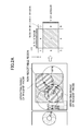
- Fig. 2A is a plan view showing non-resettable regions of the automatic analyzer equipped with the reagent transport mechanism according to this invention.
- One sensor is provided for each of the directions involved so that the analysis unit may be divided into nine blocks. This arrangement makes it possible to identify whether the reagent transport mechanism is in a non-resettable region. If the reagent transport mechanism is found in a non-resettable region, an alarm is activated.
- Fig. 2B is a flowchart of processes up to the activation of an alarm in effect when a reset is designated.
- S1 the status of an X-D1 sensor attached to the X-axis of the reagent transport mechanism is checked (S1). If this status is OFF (block 1, 2, 3, 7, 8 or 9), there is no risk of interference between the reagent transport mechanism and the reagent probe. In this case, a reset is performed (S2). If the status above is ON, the status of a Y-D1 sensor attached to the Y-axis is checked (S3). If this status is OFF (block 4 or 6), a reset is performed (S2).
- a "non-resettable region” alarm is activated (S4).
- the alarm may involve giving an indication such as "MOVE MANUALLY TO RESETTABLE REGION” prompting manual movement of the transport mechanism to a resettable region. After the movement, a reset may be performed.
- the sensors used here may be of any type including transmission-type sensors or reflection-type sensors, as long as they are capable of determining status.
- Fig. 3A is a plan view showing non-resettable regions of the automatic analyzer of this invention. Two sensors are provided for each of the directions involved so that the analysis unit may be divided into 25 blocks. This arrangement makes the non-resettable regions narrower each than those in Fig. 2A (blocks 7 and 19). The larger the number of sensors installed, the narrower the resulting blocks constituting the non-resettable regions that are narrower.
- Fig. 3B is a flowchart of processes up to the activation of an alarm in effect when a reset is designated.
- S5 the status of an X-D1 sensor attached to the X-axis of the reagent transport mechanism is checked (S5). If this status is OFF, the status of an X-D2 sensor attached to the same X-axis is checked (S6). If this status is OFF (block 1, 2, 3, 4, 5, 21, 22, 23, 24 or 25), there is no risk of interference between the reagent transport mechanism and the reagent probe. In this case, a reset is performed (S7).
- the status of a Y-D1 sensor attached to the Y-axis is checked (S8). If this status is OFF (block 16, 19 or 20), a reset is performed (S9). If this status is ON (block 17 or 18), the "non-resettable region” alarm is activated (S10).
- the status of the X-D2 sensor is checked (S11). If this status is OFF, the status of the Y-D1 sensor is checked (S12). If this status is OFF, the status of the Y-D2 sensor is checked (S13). If this status is OFF (block 6 or 10), a reset is performed (S14). If this status is ON (block 9), the "non-resettable region” alarm is activated (S15).
- the status of the Y-D2 sensor is checked (S16). If this status is OFF (block 7), a reset is performed (S17). If this status is ON (block 8), the "non-resettable region” alarm is activated (S18).
- the status of the Y-D1 sensor is checked (S19). If this status is OFF, the status of the Y-D2 sensor is checked (S20). If this status is OFF (block 11 or 15), a reset is performed (S21). If this status is ON (block 14), the "non-resettable region” alarm is activated (S22).
- the above procedure can perform reset processing in 25 blocks. If three sensors were set up for each direction, there would be 49 blocks; if four sensors were installed for each direction, there would be 81 blocks; and more sensors would make the non-resettable regions progressively narrower still. However, in view of the growing complexity of logic, space constraints, and cost restrictions, the number of sensors should preferably be two per direction.
- Figs. 2A , 2B , 3A and 3B show all operating ranges of the reagent probe to be non-resettable regions, the position of the reagent probe can be restricted since sensors are usually attached also to the reagent probe. It is then possible to further narrow the non-resettable regions by clarifying the positional relationship between the reagent probe and the reagent transport mechanism.
Landscapes
- Physics & Mathematics (AREA)
- Health & Medical Sciences (AREA)
- Life Sciences & Earth Sciences (AREA)
- Chemical & Material Sciences (AREA)
- Analytical Chemistry (AREA)
- Biochemistry (AREA)
- General Health & Medical Sciences (AREA)
- General Physics & Mathematics (AREA)
- Immunology (AREA)
- Pathology (AREA)
- Automatic Analysis And Handling Materials Therefor (AREA)
Abstract
Description
- This invention relates to an automatic analyzer for analyzing specimens of blood, urine or the like. More particularly, the invention relates to an automatic analyzer furnished with a mechanism for replacing reagent containers.
- Automatic analyzers recently need to have their reagent containers replaced more frequently than before due to higher rates at which reagents have been consumed because of the growing number of specimens to be processed and the increasing number of items to be measured. Meanwhile, there has been a need for reducing as much as possible the workload on operators so as to lower costs notably labor cost. Thus it has been desired to simplify the work of replacing reagent containers.
- Also raised have been the speeds at which automatic analyzer process specimens. It has been desired that interruptions of analyzing operations be minimized so that the equipment may continuously operate even during the work of reagent replacement.
-
Patent Document 1 discloses an automatic analyzer which includes replacement reagent storage means 2 apart from reagent storage means 1 in an analysis unit and which has reagent transport means interposed between the reagent storage means 1 and the replacement reagent storage means 2, thereby simplifying the work of reagent replacement and minimizing interruptions of analytical work. -
- Patent Document 1:
JP-2005-037171-A - In the automatic analyzer disclosed in
Patent Document 1, if the reagent transport mechanism is configured to move at the same height as the reagent probe, the mechanism and the probe can interfere with one another. If the reagent transport mechanism and the reagent probe are configured not to interfere with one another, the equipment size can become inordinately large. - An object of this invention is to provide an automatic analyzer having a reagent transport mechanism for automatically replacing reagent containers, the reagent transport mechanism being moved at the same height as those of diverse units including the reagent probe so that the equipment size may be kept small and that the analyzer may operate without problems.
- In achieving the above object, the present invention may be configured as follows:
- An automatic analyzer is provided including: a reagent container which contains a reagent; reagent container placement mechanisms which place a plurality of the reagent containers; a reagent dispensing probe with a mechanism for transferring the position of a nozzle which aspirates a predetermined amount of a reagent held in the reagent containers on the reagent container placement mechanisms, before discharging the aspirated reagent into a reaction container, and a reagent container transfer mechanism which transfers the reagent containers to the reagent container placement mechanisms. The reagent dispensing probe and the reagent container transfer mechanism are configured to interfere with one another. The automatic analyzer further includes: a position detection mechanism which detects the position of at least either the reagent dispensing probe or the reagent container transfer mechanism, and a control mechanism which, if the position detection mechanism detects that at least either the reagent dispensing probe or the reagent container transfer mechanism is in a predetermined position, performs control not to transfer at least either the reagent dispensing probe or the reagent container transfer mechanism.
- At the start of analysis or maintenance, the automatic analyzer performs reset operations of various units for operation check thereof.
- At that point, if the reagent transport mechanism of the analyzer is inside an operating range of the reagent probe, then an alarm is activated and control is performed to inhibit the reset operations.
- The reagent transport mechanism should preferably be furnished with a detector, a detection plate, etc., as means for determining whether the reagent transport mechanism is in a non-resettable region.
- In the automatic analyzer that has the reagent transport mechanism moving at the same height as that of the reagent probe, the detector and detection plate attached to the reagent transport mechanism permit the analyzer to detect the position of the reagent transport mechanism. This allows the reagent transport mechanism to transport reagent cassettes without interfering with the reagent probe.
-
- [
Fig. 1 ]
Fig. 1 is a plan view of an automatic analyzer according to the present invention. - [
Fig. 2A ]
Fig. 2A is a plan view showing non-resettable regions of the automatic analyzer of this invention. - [
Fig. 2B ]
Fig. 2B is a flowchart of processes up to the activation of an alarm in effect when a reset is designated on the automatic analyzer of this invention. - [
Fig. 3A ]
Fig. 3A is a plan view showing non-resettable regions of the automatic analyzer of this invention. - [
Fig. 3B ]
Fig. 3B is a flowchart of processes up to the activation of an alarm in effect when a reset is designated on the automatic analyzer of this invention. - Some preferred embodiments of this invention are explained below in detail by reference to the accompanying drawings.
-
Fig. 1 is a plan view of the automatic analyzer. - An automatic analyzer is made up of an
analysis unit 10 and abuffer unit 11. - The
analysis unit 10 includesreagent cabinets A 28 andB 29, areagent transport mechanism 27 that takes areagent container 12 from thebuffer unit 11 and transports the container to thereagent cabinet A 28 orB 29, and a reagent ejection andstowing mechanism 26 that ejects thereagent container 12 from theanalysis unit 10. Thebuffer unit 11 includes a replenishingreagent cabinet 20 that temporarily stores replenishing reagents and areagent ejection mechanism 25 that ejects the reagent containers. - Explained below is the procedure for transporting the
reagent containers 12 using the equipment above. - First, when an operator places a
reagent container 12 at a reagent injection port, not shown, areagent injection mechanism 24 transfers thereagent container 12 to the replenishingreagent cabinet 20. - The
reagent container 12 transferred to the replenishingreagent cabinet 20 carries an RFID tag on which is recorded such information as the remaining reagent amount, a lot number, and a use-by date. The information is read by a reagentinformation read mechanism 21 mounted on the replenishingreagent cabinet 20, and is stored into a control computer, not shown. At this point, thereagent container 12 is ejected by thereagent ejection mechanism 25 in thebuffer unit 11 if the container in question is determined to be unusable for analysis by the control computer for such reasons as expiration of the use-by date or an insufficient remaining amount of the reagent. - The reagent for which a reagent replenishment request has been issued is transferred to a cap opening position of a reagent
cap opening mechanism 23 mounted beforehand on the replenishingreagent cabinet 20. In the cap opening position, the reagent cap of thereagent container 12 is opened, and the cap is discarded into a reagentcap disposal box 34. - The
reagent cassette 12 with its reagent cap opened is sent to a reagent container transfer position inside the replenishingreagent cabinet 20. Once placed in that position, thereagent cassette 12 is sent from thebuffer unit 11 to theanalysis unit 10 by a reagentcontainer transfer mechanism 22. The replacing of reagents is timed to be performed typically in an idle cycle between exhausted reagents or an interval between the dispensing of a first reagent and that of a second reagent, provided the replacing will not cause a shortage of reagents. If the replenishment of a reagent cannot be completed in time, the sampling of specimens is suspended, the reagent is dispensed to the specimens yet to be sampled, and then the reagent is replenished. In any case, the equipment is currently in analyzing mode and not temporarily stopped to have the reagent replenished. Thus the idle time resulting from the suspension of analysis may be shortened. - The
reagent cassette 12 transferred to theanalysis unit 10 is placed on areagent rotation mechanism 32 installed in theanalysis unit 10. Thereagent rotation mechanism 32 reorients thereagent bottle 12 in a direction necessary for mounting onto thereagent cabinet A 28 orB 29. - The reoriented
reagent bottle 12 is transferred by thereagent transport mechanism 27 to thereagent cabinet A 28 orB 29 from which a reagent replacement request has been made. After transferring thereagent bottle 12 to thereagent cabinet A 28 orB 29, thereagent transport mechanism 27 transfers anyreagent container 12 of which the remaining reagent is insufficient and which needs to be replaced from the reagent cabinet A28 or B29 back to the reagent ejection and stowingmechanism 26. The reagent ejection and stowingmechanism 26 transfers thereagent container 12 to a reagent stowing part inside the reagent ejection and stowingmechanism 26; thereagent container 12 is stowed there until the operator removes it. - The automatic analyzer furnished with the
reagent transport mechanism 27 above tends to be bulky in external dimensions because of this mechanism. However, there has been a growing need in recent years for smaller-sized analyzers. Even when equipped with thereagent transport mechanism 27, the analyzer needs to remain small in external size. In view of that need, theanalysis unit 10 may be provided in which the reagent probe is moved within the same range of heights as thereagent transport mechanism 27 so that the external dimensions of the analyzer remain the same. - Where the
reagent transport mechanism 27 is moved at the same height as the reagent probe, there is a risk of interference therebetween. In order to avoid the interference, non-resettable regions are established. -
Fig. 2A is a plan view showing non-resettable regions of the automatic analyzer equipped with the reagent transport mechanism according to this invention. One sensor is provided for each of the directions involved so that the analysis unit may be divided into nine blocks. This arrangement makes it possible to identify whether the reagent transport mechanism is in a non-resettable region. If the reagent transport mechanism is found in a non-resettable region, an alarm is activated. -
Fig. 2B is a flowchart of processes up to the activation of an alarm in effect when a reset is designated. First, the status of an X-D1 sensor attached to the X-axis of the reagent transport mechanism is checked (S1). If this status is OFF (block - The sensors used here may be of any type including transmission-type sensors or reflection-type sensors, as long as they are capable of determining status.
-
Fig. 3A is a plan view showing non-resettable regions of the automatic analyzer of this invention. Two sensors are provided for each of the directions involved so that the analysis unit may be divided into 25 blocks. This arrangement makes the non-resettable regions narrower each than those inFig. 2A (blocks 7 and 19). The larger the number of sensors installed, the narrower the resulting blocks constituting the non-resettable regions that are narrower. -
Fig. 3B is a flowchart of processes up to the activation of an alarm in effect when a reset is designated. First, the status of an X-D1 sensor attached to the X-axis of the reagent transport mechanism is checked (S5). If this status is OFF, the status of an X-D2 sensor attached to the same X-axis is checked (S6). If this status is OFF (block - If the status is ON in S6, the status of a Y-D1 sensor attached to the Y-axis is checked (S8). If this status is OFF (block 16, 19 or 20), a reset is performed (S9). If this status is ON (block 17 or 18), the "non-resettable region" alarm is activated (S10).
- If the status is ON in S5, the status of the X-D2 sensor is checked (S11). If this status is OFF, the status of the Y-D1 sensor is checked (S12). If this status is OFF, the status of the Y-D2 sensor is checked (S13). If this status is OFF (block 6 or 10), a reset is performed (S14). If this status is ON (block 9), the "non-resettable region" alarm is activated (S15).
- If the status is ON in S11, the status of the Y-D2 sensor is checked (S16). If this status is OFF (block 7), a reset is performed (S17). If this status is ON (block 8), the "non-resettable region" alarm is activated (S18).
- If the status is ON in S10, the status of the Y-D1 sensor is checked (S19). If this status is OFF, the status of the Y-D2 sensor is checked (S20). If this status is OFF (block 11 or 15), a reset is performed (S21). If this status is ON (block 14), the "non-resettable region" alarm is activated (S22).
- If the status is ON in S18 (block 12 or 13), the "non-resettable region" alarm is activated (S23).
- The above procedure can perform reset processing in 25 blocks. If three sensors were set up for each direction, there would be 49 blocks; if four sensors were installed for each direction, there would be 81 blocks; and more sensors would make the non-resettable regions progressively narrower still. However, in view of the growing complexity of logic, space constraints, and cost restrictions, the number of sensors should preferably be two per direction.
- One way of narrowing the non-resettable regions is by reviewing the operating ranges of the reagent probe. Whereas
Figs. 2A ,2B ,3A and3B show all operating ranges of the reagent probe to be non-resettable regions, the position of the reagent probe can be restricted since sensors are usually attached also to the reagent probe. It is then possible to further narrow the non-resettable regions by clarifying the positional relationship between the reagent probe and the reagent transport mechanism. -
- 10
- Analysis unit
- 11
- Buffer unit
- 12
- Reagent container (also called reagent cassette or reagent bottle)
- 20
- Replenishing reagent cabinet
- 21
- Reagent information read mechanism
- 22
- Reagent transfer mechanism
- 23
- Reagent cap opening mechanism
- 24
- Reagent injection mechanism
- 25
- Reagent ejection mechanism
- 26
- Reagent ejection and stowing mechanism
- 27
- Reagent transport mechanism
- 28
- Reagent cabinet A
- 29
- Reagent cabinet B
- 30
- Reagent injection port A
- 31
- Reagent injection port B
- 32
- Reagent rotation mechanism
- 33
- Reaction mechanism
- 34
- Reagent cap disposal box
- 35
- Reagent injection port
Claims (6)
- An automatic analyzer comprising:a reagent container (12) which contains a reagent;reagent container placement mechanisms (28, 29) which place a plurality of the reagent containers;a reagent dispensing probe with a mechanism for transferring the position of a nozzle which aspirates a predetermined amount of a reagent held in the reagent containers on the reagent container placement mechanisms, before discharging the aspirated reagent into a reaction container, anda reagent container transfer mechanism (27) which transfers the reagent containers to the reagent container placement mechanisms;wherein the reagent dispensing probe and the reagent container transfer mechanism are configured to interfere with one another;the automatic analyzer further including:a position detection mechanism which detects the position of at least either the reagent dispensing probe or the reagent container transfer mechanism, anda control mechanism which, if the position detection mechanism detects that at least either the reagent dispensing probe or the reagent container transfer mechanism is in a predetermined position, performs control not to transfer at least either the reagent dispensing probe or the reagent container transfer mechanism.
- The automatic analyzer according to claim 1, wherein the position detection mechanism includes a detection plate installed along a transfer locus of either the reagent dispensing probe or the reagent container transfer mechanism, and a detector which detects the detection plate attached to either the reagent dispensing probe or the reagent container transfer mechanism.
- The automatic analyzer according to claim 1, wherein the reagent dispensing probe includes an arm part which rotates around a rotation axis, and a nozzle attached to the arm part.
- The automatic analyzer according to claim 1, wherein the reagent container transfer mechanism includes a holding part for taking hold of the reagent containers and a holding part transfer mechanism for transferring the holding part.
- The automatic analyzer according to claim 1, wherein the position detection mechanism divides a detection area into a plurality of regions so as to detect the region in which either the reagent dispensing probe or the reagent container transfer mechanism is present.
- The automatic analyzer according to claim 1, wherein, if the position detection mechanism detects that at least either the reagent dispensing probe or the reagent container transfer mechanism is in the predetermined position, then the position detection mechanism prevents transfer of at least either the reagent dispensing probe or the reagent container transfer mechanism by inhibiting a reset operation thereof.
Applications Claiming Priority (2)
| Application Number | Priority Date | Filing Date | Title |
|---|---|---|---|
| JP2010156311A JP5097804B2 (en) | 2010-07-09 | 2010-07-09 | Automatic analyzer |
| PCT/JP2011/065060 WO2012005168A1 (en) | 2010-07-09 | 2011-06-30 | Automatic analyzer |
Publications (3)
| Publication Number | Publication Date |
|---|---|
| EP2592424A1 true EP2592424A1 (en) | 2013-05-15 |
| EP2592424A4 EP2592424A4 (en) | 2017-11-22 |
| EP2592424B1 EP2592424B1 (en) | 2022-05-11 |
Family
ID=45441149
Family Applications (1)
| Application Number | Title | Priority Date | Filing Date |
|---|---|---|---|
| EP11803502.1A Active EP2592424B1 (en) | 2010-07-09 | 2011-06-30 | Automatic analyzer |
Country Status (5)
| Country | Link |
|---|---|
| US (1) | US9052301B2 (en) |
| EP (1) | EP2592424B1 (en) |
| JP (1) | JP5097804B2 (en) |
| CN (1) | CN102985830B (en) |
| WO (1) | WO2012005168A1 (en) |
Families Citing this family (7)
| Publication number | Priority date | Publication date | Assignee | Title |
|---|---|---|---|---|
| JP5854647B2 (en) * | 2011-05-31 | 2016-02-09 | 株式会社東芝 | Automatic analyzer |
| JP6026753B2 (en) * | 2012-02-23 | 2016-11-16 | 株式会社日立ハイテクノロジーズ | Automatic analyzer |
| JP6879871B2 (en) * | 2017-09-07 | 2021-06-02 | 株式会社日立ハイテク | Automatic analyzer |
| EP3971580B1 (en) * | 2019-05-16 | 2024-07-03 | Hitachi High-Tech Corporation | Automated analyzer |
| WO2022230502A1 (en) * | 2021-04-27 | 2022-11-03 | 株式会社日立ハイテク | Automated analysis device |
| CN116413460A (en) * | 2021-12-31 | 2023-07-11 | 力合科技(湖南)股份有限公司 | Automatic solution analysis device |
| CN118304950A (en) * | 2022-12-29 | 2024-07-09 | 中元汇吉生物技术股份有限公司 | Probe mechanism and control method thereof, and sample analyzer |
Family Cites Families (15)
| Publication number | Priority date | Publication date | Assignee | Title |
|---|---|---|---|---|
| US5051238A (en) * | 1987-11-20 | 1991-09-24 | Hitachi, Ltd. | Automatic analyzing system |
| JPH09196925A (en) | 1996-01-19 | 1997-07-31 | Hitachi Ltd | Automatic analyzer |
| US6429016B1 (en) * | 1999-10-01 | 2002-08-06 | Isis Pharmaceuticals, Inc. | System and method for sample positioning in a robotic system |
| US7458483B2 (en) * | 2001-04-24 | 2008-12-02 | Abbott Laboratories, Inc. | Assay testing diagnostic analyzer |
| JP2004317269A (en) * | 2003-04-16 | 2004-11-11 | Hitachi High-Technologies Corp | Automatic analyzer |
| JP4033060B2 (en) * | 2003-07-17 | 2008-01-16 | 株式会社日立ハイテクノロジーズ | Automatic analyzer |
| JP4221349B2 (en) * | 2004-09-17 | 2009-02-12 | 株式会社日立ハイテクノロジーズ | Automatic analyzer |
| JP4538365B2 (en) * | 2005-04-25 | 2010-09-08 | 株式会社日立ハイテクノロジーズ | Reagent cooler and automatic analyzer equipped with the same |
| JP4861762B2 (en) | 2006-07-13 | 2012-01-25 | ベックマン コールター, インコーポレイテッド | Automatic analyzer |
| JP4500822B2 (en) * | 2007-02-19 | 2010-07-14 | 株式会社日立ハイテクノロジーズ | Automatic analyzer |
| EP2175259A4 (en) * | 2007-06-19 | 2011-11-02 | Beckman Coulter Inc | Method of specifying error and analyzer |
| JP5486160B2 (en) * | 2008-02-27 | 2014-05-07 | シスメックス株式会社 | Sample analyzer, abnormality control method thereof, and program for sample analyzer |
| US8473085B2 (en) * | 2008-04-30 | 2013-06-25 | Perkinelmer Las, Inc. | Mutex-mediated control of spatial access by appliances moveable over a common physical space |
| JP2010145284A (en) * | 2008-12-19 | 2010-07-01 | Toshiba Corp | Automatic analyzer |
| JP2010151519A (en) * | 2008-12-24 | 2010-07-08 | Hitachi High-Technologies Corp | Automatic analyzer |
-
2010
- 2010-07-09 JP JP2010156311A patent/JP5097804B2/en active Active
-
2011
- 2011-06-30 US US13/809,161 patent/US9052301B2/en active Active
- 2011-06-30 WO PCT/JP2011/065060 patent/WO2012005168A1/en not_active Ceased
- 2011-06-30 CN CN201180033674.6A patent/CN102985830B/en active Active
- 2011-06-30 EP EP11803502.1A patent/EP2592424B1/en active Active
Non-Patent Citations (1)
| Title |
|---|
| See references of WO2012005168A1 * |
Also Published As
| Publication number | Publication date |
|---|---|
| EP2592424A4 (en) | 2017-11-22 |
| CN102985830A (en) | 2013-03-20 |
| US9052301B2 (en) | 2015-06-09 |
| JP5097804B2 (en) | 2012-12-12 |
| US20130115134A1 (en) | 2013-05-09 |
| WO2012005168A1 (en) | 2012-01-12 |
| CN102985830B (en) | 2014-12-03 |
| EP2592424B1 (en) | 2022-05-11 |
| JP2012018104A (en) | 2012-01-26 |
Similar Documents
| Publication | Publication Date | Title |
|---|---|---|
| US9052301B2 (en) | Automatic analyzer | |
| CN101251544B (en) | Automatic analyzer | |
| CN102818907B (en) | Automatic analyzer | |
| EP1477816B1 (en) | Automatic analyzer | |
| EP1248113B1 (en) | Automatic analyzer and rack transfer device | |
| EP2647997B1 (en) | Automatic analytical apparatus | |
| EP2647998B1 (en) | Automatic analytical apparatus | |
| EP2672271B1 (en) | Automatic analysis system | |
| JP2005037171A (en) | Automatic analyzer | |
| JP2017067794A (en) | Automatic analyzer | |
| WO2018155049A1 (en) | Automated analyzer | |
| JP2012021862A (en) | Automatic analyzer | |
| US8728395B2 (en) | Automatic analyzer | |
| JP6210891B2 (en) | Automatic analyzer | |
| JP5178891B2 (en) | Automatic analyzer | |
| JP2006337386A (en) | Automatic analyzer | |
| US20250224416A1 (en) | Automatic analyzer | |
| JP7614360B2 (en) | Automated analyzer and guidance method for the automated analyzer | |
| CN113795758A (en) | Automatic analyzer |
Legal Events
| Date | Code | Title | Description |
|---|---|---|---|
| PUAI | Public reference made under article 153(3) epc to a published international application that has entered the european phase |
Free format text: ORIGINAL CODE: 0009012 |
|
| 17P | Request for examination filed |
Effective date: 20121220 |
|
| AK | Designated contracting states |
Kind code of ref document: A1 Designated state(s): AL AT BE BG CH CY CZ DE DK EE ES FI FR GB GR HR HU IE IS IT LI LT LU LV MC MK MT NL NO PL PT RO RS SE SI SK SM TR |
|
| DAX | Request for extension of the european patent (deleted) | ||
| RA4 | Supplementary search report drawn up and despatched (corrected) |
Effective date: 20171024 |
|
| RIC1 | Information provided on ipc code assigned before grant |
Ipc: G01N 35/02 20060101AFI20171018BHEP Ipc: G01N 35/04 20060101ALI20171018BHEP Ipc: G01N 35/00 20060101ALI20171018BHEP |
|
| STAA | Information on the status of an ep patent application or granted ep patent |
Free format text: STATUS: EXAMINATION IS IN PROGRESS |
|
| 17Q | First examination report despatched |
Effective date: 20191114 |
|
| RAP1 | Party data changed (applicant data changed or rights of an application transferred) |
Owner name: HITACHI HIGH-TECH CORPORATION |
|
| GRAP | Despatch of communication of intention to grant a patent |
Free format text: ORIGINAL CODE: EPIDOSNIGR1 |
|
| STAA | Information on the status of an ep patent application or granted ep patent |
Free format text: STATUS: GRANT OF PATENT IS INTENDED |
|
| INTG | Intention to grant announced |
Effective date: 20220131 |
|
| GRAS | Grant fee paid |
Free format text: ORIGINAL CODE: EPIDOSNIGR3 |
|
| GRAA | (expected) grant |
Free format text: ORIGINAL CODE: 0009210 |
|
| STAA | Information on the status of an ep patent application or granted ep patent |
Free format text: STATUS: THE PATENT HAS BEEN GRANTED |
|
| AK | Designated contracting states |
Kind code of ref document: B1 Designated state(s): AL AT BE BG CH CY CZ DE DK EE ES FI FR GB GR HR HU IE IS IT LI LT LU LV MC MK MT NL NO PL PT RO RS SE SI SK SM TR |
|
| REG | Reference to a national code |
Ref country code: GB Ref legal event code: FG4D |
|
| REG | Reference to a national code |
Ref country code: CH Ref legal event code: EP |
|
| REG | Reference to a national code |
Ref country code: AT Ref legal event code: REF Ref document number: 1491850 Country of ref document: AT Kind code of ref document: T Effective date: 20220515 |
|
| REG | Reference to a national code |
Ref country code: DE Ref legal event code: R096 Ref document number: 602011072878 Country of ref document: DE |
|
| REG | Reference to a national code |
Ref country code: IE Ref legal event code: FG4D |
|
| REG | Reference to a national code |
Ref country code: LT Ref legal event code: MG9D |
|
| REG | Reference to a national code |
Ref country code: NL Ref legal event code: MP Effective date: 20220511 |
|
| REG | Reference to a national code |
Ref country code: AT Ref legal event code: MK05 Ref document number: 1491850 Country of ref document: AT Kind code of ref document: T Effective date: 20220511 |
|
| PG25 | Lapsed in a contracting state [announced via postgrant information from national office to epo] |
Ref country code: SE Free format text: LAPSE BECAUSE OF FAILURE TO SUBMIT A TRANSLATION OF THE DESCRIPTION OR TO PAY THE FEE WITHIN THE PRESCRIBED TIME-LIMIT Effective date: 20220511 Ref country code: PT Free format text: LAPSE BECAUSE OF FAILURE TO SUBMIT A TRANSLATION OF THE DESCRIPTION OR TO PAY THE FEE WITHIN THE PRESCRIBED TIME-LIMIT Effective date: 20220912 Ref country code: NO Free format text: LAPSE BECAUSE OF FAILURE TO SUBMIT A TRANSLATION OF THE DESCRIPTION OR TO PAY THE FEE WITHIN THE PRESCRIBED TIME-LIMIT Effective date: 20220811 Ref country code: NL Free format text: LAPSE BECAUSE OF FAILURE TO SUBMIT A TRANSLATION OF THE DESCRIPTION OR TO PAY THE FEE WITHIN THE PRESCRIBED TIME-LIMIT Effective date: 20220511 Ref country code: LT Free format text: LAPSE BECAUSE OF FAILURE TO SUBMIT A TRANSLATION OF THE DESCRIPTION OR TO PAY THE FEE WITHIN THE PRESCRIBED TIME-LIMIT Effective date: 20220511 Ref country code: HR Free format text: LAPSE BECAUSE OF FAILURE TO SUBMIT A TRANSLATION OF THE DESCRIPTION OR TO PAY THE FEE WITHIN THE PRESCRIBED TIME-LIMIT Effective date: 20220511 Ref country code: GR Free format text: LAPSE BECAUSE OF FAILURE TO SUBMIT A TRANSLATION OF THE DESCRIPTION OR TO PAY THE FEE WITHIN THE PRESCRIBED TIME-LIMIT Effective date: 20220812 Ref country code: FI Free format text: LAPSE BECAUSE OF FAILURE TO SUBMIT A TRANSLATION OF THE DESCRIPTION OR TO PAY THE FEE WITHIN THE PRESCRIBED TIME-LIMIT Effective date: 20220511 Ref country code: ES Free format text: LAPSE BECAUSE OF FAILURE TO SUBMIT A TRANSLATION OF THE DESCRIPTION OR TO PAY THE FEE WITHIN THE PRESCRIBED TIME-LIMIT Effective date: 20220511 Ref country code: BG Free format text: LAPSE BECAUSE OF FAILURE TO SUBMIT A TRANSLATION OF THE DESCRIPTION OR TO PAY THE FEE WITHIN THE PRESCRIBED TIME-LIMIT Effective date: 20220811 Ref country code: AT Free format text: LAPSE BECAUSE OF FAILURE TO SUBMIT A TRANSLATION OF THE DESCRIPTION OR TO PAY THE FEE WITHIN THE PRESCRIBED TIME-LIMIT Effective date: 20220511 |
|
| PG25 | Lapsed in a contracting state [announced via postgrant information from national office to epo] |
Ref country code: RS Free format text: LAPSE BECAUSE OF FAILURE TO SUBMIT A TRANSLATION OF THE DESCRIPTION OR TO PAY THE FEE WITHIN THE PRESCRIBED TIME-LIMIT Effective date: 20220511 Ref country code: PL Free format text: LAPSE BECAUSE OF FAILURE TO SUBMIT A TRANSLATION OF THE DESCRIPTION OR TO PAY THE FEE WITHIN THE PRESCRIBED TIME-LIMIT Effective date: 20220511 Ref country code: LV Free format text: LAPSE BECAUSE OF FAILURE TO SUBMIT A TRANSLATION OF THE DESCRIPTION OR TO PAY THE FEE WITHIN THE PRESCRIBED TIME-LIMIT Effective date: 20220511 Ref country code: IS Free format text: LAPSE BECAUSE OF FAILURE TO SUBMIT A TRANSLATION OF THE DESCRIPTION OR TO PAY THE FEE WITHIN THE PRESCRIBED TIME-LIMIT Effective date: 20220911 |
|
| PG25 | Lapsed in a contracting state [announced via postgrant information from national office to epo] |
Ref country code: SM Free format text: LAPSE BECAUSE OF FAILURE TO SUBMIT A TRANSLATION OF THE DESCRIPTION OR TO PAY THE FEE WITHIN THE PRESCRIBED TIME-LIMIT Effective date: 20220511 Ref country code: SK Free format text: LAPSE BECAUSE OF FAILURE TO SUBMIT A TRANSLATION OF THE DESCRIPTION OR TO PAY THE FEE WITHIN THE PRESCRIBED TIME-LIMIT Effective date: 20220511 Ref country code: RO Free format text: LAPSE BECAUSE OF FAILURE TO SUBMIT A TRANSLATION OF THE DESCRIPTION OR TO PAY THE FEE WITHIN THE PRESCRIBED TIME-LIMIT Effective date: 20220511 Ref country code: EE Free format text: LAPSE BECAUSE OF FAILURE TO SUBMIT A TRANSLATION OF THE DESCRIPTION OR TO PAY THE FEE WITHIN THE PRESCRIBED TIME-LIMIT Effective date: 20220511 Ref country code: DK Free format text: LAPSE BECAUSE OF FAILURE TO SUBMIT A TRANSLATION OF THE DESCRIPTION OR TO PAY THE FEE WITHIN THE PRESCRIBED TIME-LIMIT Effective date: 20220511 Ref country code: CZ Free format text: LAPSE BECAUSE OF FAILURE TO SUBMIT A TRANSLATION OF THE DESCRIPTION OR TO PAY THE FEE WITHIN THE PRESCRIBED TIME-LIMIT Effective date: 20220511 |
|
| REG | Reference to a national code |
Ref country code: CH Ref legal event code: PL |
|
| REG | Reference to a national code |
Ref country code: DE Ref legal event code: R097 Ref document number: 602011072878 Country of ref document: DE |
|
| REG | Reference to a national code |
Ref country code: BE Ref legal event code: MM Effective date: 20220630 |
|
| PG25 | Lapsed in a contracting state [announced via postgrant information from national office to epo] |
Ref country code: MC Free format text: LAPSE BECAUSE OF FAILURE TO SUBMIT A TRANSLATION OF THE DESCRIPTION OR TO PAY THE FEE WITHIN THE PRESCRIBED TIME-LIMIT Effective date: 20220511 |
|
| PLBE | No opposition filed within time limit |
Free format text: ORIGINAL CODE: 0009261 |
|
| STAA | Information on the status of an ep patent application or granted ep patent |
Free format text: STATUS: NO OPPOSITION FILED WITHIN TIME LIMIT |
|
| PG25 | Lapsed in a contracting state [announced via postgrant information from national office to epo] |
Ref country code: AL Free format text: LAPSE BECAUSE OF FAILURE TO SUBMIT A TRANSLATION OF THE DESCRIPTION OR TO PAY THE FEE WITHIN THE PRESCRIBED TIME-LIMIT Effective date: 20220511 |
|
| 26N | No opposition filed |
Effective date: 20230214 |
|
| GBPC | Gb: european patent ceased through non-payment of renewal fee |
Effective date: 20220811 |
|
| PG25 | Lapsed in a contracting state [announced via postgrant information from national office to epo] |
Ref country code: LU Free format text: LAPSE BECAUSE OF NON-PAYMENT OF DUE FEES Effective date: 20220630 Ref country code: LI Free format text: LAPSE BECAUSE OF NON-PAYMENT OF DUE FEES Effective date: 20220630 Ref country code: IE Free format text: LAPSE BECAUSE OF NON-PAYMENT OF DUE FEES Effective date: 20220630 Ref country code: CH Free format text: LAPSE BECAUSE OF NON-PAYMENT OF DUE FEES Effective date: 20220630 |
|
| PG25 | Lapsed in a contracting state [announced via postgrant information from national office to epo] |
Ref country code: SI Free format text: LAPSE BECAUSE OF FAILURE TO SUBMIT A TRANSLATION OF THE DESCRIPTION OR TO PAY THE FEE WITHIN THE PRESCRIBED TIME-LIMIT Effective date: 20220511 Ref country code: BE Free format text: LAPSE BECAUSE OF NON-PAYMENT OF DUE FEES Effective date: 20220630 |
|
| PG25 | Lapsed in a contracting state [announced via postgrant information from national office to epo] |
Ref country code: GB Free format text: LAPSE BECAUSE OF NON-PAYMENT OF DUE FEES Effective date: 20220811 |
|
| PG25 | Lapsed in a contracting state [announced via postgrant information from national office to epo] |
Ref country code: IT Free format text: LAPSE BECAUSE OF FAILURE TO SUBMIT A TRANSLATION OF THE DESCRIPTION OR TO PAY THE FEE WITHIN THE PRESCRIBED TIME-LIMIT Effective date: 20220511 |
|
| PG25 | Lapsed in a contracting state [announced via postgrant information from national office to epo] |
Ref country code: HU Free format text: LAPSE BECAUSE OF FAILURE TO SUBMIT A TRANSLATION OF THE DESCRIPTION OR TO PAY THE FEE WITHIN THE PRESCRIBED TIME-LIMIT; INVALID AB INITIO Effective date: 20110630 |
|
| PG25 | Lapsed in a contracting state [announced via postgrant information from national office to epo] |
Ref country code: MK Free format text: LAPSE BECAUSE OF FAILURE TO SUBMIT A TRANSLATION OF THE DESCRIPTION OR TO PAY THE FEE WITHIN THE PRESCRIBED TIME-LIMIT Effective date: 20220511 Ref country code: CY Free format text: LAPSE BECAUSE OF FAILURE TO SUBMIT A TRANSLATION OF THE DESCRIPTION OR TO PAY THE FEE WITHIN THE PRESCRIBED TIME-LIMIT Effective date: 20220511 |
|
| PG25 | Lapsed in a contracting state [announced via postgrant information from national office to epo] |
Ref country code: TR Free format text: LAPSE BECAUSE OF FAILURE TO SUBMIT A TRANSLATION OF THE DESCRIPTION OR TO PAY THE FEE WITHIN THE PRESCRIBED TIME-LIMIT Effective date: 20220511 |
|
| PG25 | Lapsed in a contracting state [announced via postgrant information from national office to epo] |
Ref country code: MT Free format text: LAPSE BECAUSE OF FAILURE TO SUBMIT A TRANSLATION OF THE DESCRIPTION OR TO PAY THE FEE WITHIN THE PRESCRIBED TIME-LIMIT Effective date: 20220511 |
|
| PG25 | Lapsed in a contracting state [announced via postgrant information from national office to epo] |
Ref country code: BG Free format text: LAPSE BECAUSE OF FAILURE TO SUBMIT A TRANSLATION OF THE DESCRIPTION OR TO PAY THE FEE WITHIN THE PRESCRIBED TIME-LIMIT Effective date: 20220511 |
|
| PG25 | Lapsed in a contracting state [announced via postgrant information from national office to epo] |
Ref country code: BG Free format text: LAPSE BECAUSE OF FAILURE TO SUBMIT A TRANSLATION OF THE DESCRIPTION OR TO PAY THE FEE WITHIN THE PRESCRIBED TIME-LIMIT Effective date: 20220511 |
|
| PGFP | Annual fee paid to national office [announced via postgrant information from national office to epo] |
Ref country code: DE Payment date: 20260520 Year of fee payment: 16 |
|
| PGFP | Annual fee paid to national office [announced via postgrant information from national office to epo] |
Ref country code: FR Payment date: 20260521 Year of fee payment: 16 |