EP2591663B1 - Machine agricole - Google Patents
Machine agricole Download PDFInfo
- Publication number
- EP2591663B1 EP2591663B1 EP12007573.4A EP12007573A EP2591663B1 EP 2591663 B1 EP2591663 B1 EP 2591663B1 EP 12007573 A EP12007573 A EP 12007573A EP 2591663 B1 EP2591663 B1 EP 2591663B1
- Authority
- EP
- European Patent Office
- Prior art keywords
- piston rod
- pistons
- cylinder
- piston
- agricultural machine
- Prior art date
- Legal status (The legal status is an assumption and is not a legal conclusion. Google has not performed a legal analysis and makes no representation as to the accuracy of the status listed.)
- Active
Links
Images


Classifications
-
- A—HUMAN NECESSITIES
- A01—AGRICULTURE; FORESTRY; ANIMAL HUSBANDRY; HUNTING; TRAPPING; FISHING
- A01D—HARVESTING; MOWING
- A01D78/00—Haymakers with tines moving with respect to the machine
- A01D78/08—Haymakers with tines moving with respect to the machine with tine-carrying rotary heads or wheels
- A01D78/10—Haymakers with tines moving with respect to the machine with tine-carrying rotary heads or wheels the tines rotating about a substantially vertical axis
- A01D78/1007—Arrangements to facilitate transportation specially adapted therefor
- A01D78/1014—Folding frames
Definitions
- the present invention relates to an agricultural machine, which may be designed as a haymaking machine, preferably in the form of a turret or rake, with a mountable to a tractor chassis, which is supported via a chassis on the ground, and at least one working unit for forage or tillage, which is mounted on a support frame, which is lifted relative to the chassis together with the working unit of a lifting / pivoting device in a headland and a transport position, wherein the Hubschwenkvoriques comprises an actuating cylinder unit with a plurality of cylinders and pistons.
- haymaking machines with larger working widths, which include several juxtaposed or running in different lanes rotary rake
- the support frame which carries the haymaking units, usually hinged about a horizontal transverse axis pivotally mounted on the running frame, so that the support frame together with the arranged thereon haymaking aggregates in the form of rotary rakes forward / can be pivoted or raised, wherein the support frame may optionally have hinged side parts, which are pivoted in the transport position to the front.
- Such haymaking machines in the form of caterpillars, for example, from the publications EP 18 59 670 A1 .
- EP 21 79 641 A1 or WO 2010/074558 A1 known.
- the rotary rakes are then in the transport position with the rake tines to the outside.
- the folded-up to the front of the traveling frame rotary rakes are tilted in the transport position mentioned with their Rech Vietnameseelachsen, so that said Rech Vietnameseelachsen are aligned approximately lying transversely to the direction of travel.
- Such tilting of the rotary rake in the transport position is necessary in order to achieve a sufficiently narrow road transport width in the desired manner.
- the support frame after folding the side panels can be pivoted once again about the aforementioned transverse axis a piece, so that the support frame side parts or drive the working units attached to it into support troughs and be supported there.
- the adjusting movement which has to perform the Hubschwenkvorraum, however, relatively complicated, since the pivotal movement must be stopped about the horizontal transverse axis before reaching the full end position in order to be able to fold the side parts, so that a corresponding actuating cylinder is not easily driven into its final position can, but must be stopped first.
- the control of the adjusting cylinder unit becomes even more complicated when the support frame is not only to be moved back and forth between working position and transport position, but also to be mobile in a headland position.
- the working tools are regularly excavated only a short distance from the ground, in order to be able to drive over swaths that have already gathered.
- the excavation should be relatively limited so that the drive can continue to run and the drive shafts here experience no excessive buckling.
- the lifting into the headland position is effected by the same adjusting cylinder unit, it must be able to approach another intermediate position.
- either relatively complex hydraulic control means such as check valves, control valves and the like can be used or mechanically pivotable stops are provided, so that the adjusting movement can be stopped or interrupted without having to provide an appropriate pressure control. Both are unsatisfactory.
- the present invention has for its object to provide an improved agricultural machine of the type mentioned above, which avoids the disadvantages of the prior art and the latter develops in an advantageous manner.
- a precise starting of both the headland position and the transport position is to be made possible with the simplest possible pressure control without complex valve arrangements, in particular, a fine, two-stage starting the transport position should be possible.
- a piston rod in the same cylinder at least two pistons are each assigned to be displaceable, so that the piston rod is displaceable relative to each of the two pistons, each of the pistons a different travel and thus a different actuating movement of the piston rod plays.
- a plurality of pistons are accommodated in at least one of the cylinders of the actuating cylinder unit and are displaceably mounted relative to a piston rod displaceably received in the cylinder, wherein the plurality of pistons have different, respectively limited, displaced regions relative to the piston rod.
- the displacement paths of the two pistons received in the same cylinder can be formed without overlapping on or relative to the common piston rod.
- the freedom of overlap of the displacement paths allows an individual adjustment of the piston cross-sections as well as a sectionwise adjustment of the piston rod cross-sections to the respective setting task.
- the pistons may have the same outer diameter in the invention, but they do not have.
- the piston rod diameter can be individually adapted to only one of the two pistons, in order to adapt by the resulting effective cross-sectional area on which the fluid pressure is effective to the desired restoring forces.
- two independent travel of the piston rod relative to said cylinder can be generated by the two pistons received in the same cylinder, in particular such that by applying a piston regardless of the application of the Another piston is a first travel and another position can be generated by acting on the other piston regardless of the application of the aforementioned one piston.
- the travel ranges which can be generated in each case can have different lengths in order to be able to solve different lifting tasks by acting on the different pistons.
- one of the two pistons received in the same cylinder can be provided for extending the piston rod, while the other of the two pistons received in the same cylinder is provided for retracting the piston rod into said cylinder.
- one of the two pistons received in the same cylinder is detachable from the piston rod and removable in the axial direction, so that the piston rod is movable with its rod end beyond the end position of said piston and away from it.
- said piston has a piston rod facing Axialdruck structure for pushing away, in particular extension of the piston rod. If the said piston reaches its end position provided in the direction of the travel, the piston rod can nonetheless continue to move, for example if a corresponding force acts on the actuating cylinder unit from the working unit and / or under the control of the further travel by the other displaceable piston.
- said cylinder receives a piston slidably seated on the piston rod and secured against slipping off the piston rod.
- the piston rod has for this purpose before its free end or also directly at its free end an end stop surface, which prevents a pushing down of said piston beyond the free end of the piston rod addition.
- Piston rod provided between the two slidably received in said cylinder piston.
- the piston rod advantageously has between the two pistons a free end, wherein in the region of the free end, the piston rod may have a thickening, such as a shoulder or the like.
- the said free end can form an axial pressure surface against which the piston rod detachably arranged piston can press axially to extend the piston rod.
- the said thickening in the region of the piston rod end can prevent the other displaceable piston from slipping off the piston rod.
- a free end of the piston rod between the two pistons is advantageous, but not mandatory.
- a blind-hole-like depression may be provided on the one piston or also a through-bore if the piston rod is designed to be sufficiently long, if necessary passing through the cylinder on both sides.
- the aforementioned embodiment is preferred with a free end of the piston rod between the two pistons, since on the one hand double fits avoided and on the other hand, a short, compact design can be achieved.
- the displacements of the two pistons are separated from each other in the common cylinder or the said pistons are accommodated in separate chambers of the cylinder.
- the cylinder between the piston may have at least one radially inwardly projecting stop, which limits the travel of the piston and separates from each other.
- the said stop is advantageously designed in such a way that the piston rod with its free End and / or with her a piston locking stop on said inwardly projecting stop of the cylinder is implantfahrbar so that the subdivision of the cylinder or the limitation of the travel of the piston in the cylinder does not hinder the mobility of the piston rod.
- the plurality of pistons in the common cylinder on opposite sides of the piston can be pressurized, in particular such that the piston rod can be held or clamped in an intermediate position relative to the cylinder of the two pistons.
- Said intermediate layer means a position of the piston rod, which lies between the maximum retracted and the maximum extended position of said piston rod relative to the cylinder.
- the adjusting cylinder unit comprises at least one further cylinder, which may be formed in a conventional manner as a double-acting cylinder in development of the invention.
- a piston can be received in the other cylinder, which can be axially fixedly connected to the piston rod.
- the cylinder may in this case have two pressure chambers lying on opposite sides of said piston in the development of the invention, so that retracted by the application of the opposite pressure chambers, the piston rod and can be extended.
- a single-acting cylinder training can be provided, for example, if it is ensured that always sufficient pulling force, or pressure force acts on the cylinder, for example as a result of the weight during the to be performed by the cylinder travel of the working unit to be adjusted.
- a double-acting design is preferred in order to be able to actively carry out adjusting movements in both directions.
- the actuating cylinder unit may have two cylinders which are seated on a common piston rod, wherein said piston rod by independent control movements on the one hand relative to the one cylinder and / or retractable and on the other hand relative to the other cylinder and / or or extendable.
- two cylinders could also be connected to one another, so to speak, back to back, it being possible for two piston rods to be provided, which are each individually assigned to one of the two cylinders.
- one of the two cylinders can cause a travel between headland position and transport position, while the other cylinder on the one hand provides a travel between working position and headland position and on the other hand a travel directly into or out of the transport position.
- the travel to the transport position can therefore be divided or subdivided in particular such that a lowering or lifting in or out of the transport position is controlled by a different piston than the remaining travel between transport position and headland position.
- Such a multi-stage or subdivided method in the transport position can be particularly advantageous if the working units or the working aggregates supporting frame are supported in the transport position on a support surface or in a support trough, for example, to intercept shocks and vibrations of bumps ago and To prevent excessive loads on the Hubschwenkvorraum.
- a stepwise or subdivided movability into the transport position can also be advantageous if, during or after reaching the transport position, a further auxiliary unit is to be actuated or moved, in particular by the working unit moving into the transport position or the supporting frame carrying the working unit itself, ie if the working unit or the support frame should act as a kind of Stellaktor for said auxiliary unit, so to speak.
- additional units can be of different nature, in particular, a protective barrier can be driven in front of the working unit when the working unit has reached its transport position to prevent collisions with the working unit.
- the working units can be secured in the transport position by a vorgeblendetes protection element and the protective element wegbewegbar not to hinder the movement of the working units in and out of the transport position and to be able to maintain the conventional kinematics for spending in the transport position. Due to the Wegbewegberry the collision protection this can also be arranged in the optimum position in front of the working units regardless of possible collisions hereby.
- a protective barrier may be movably mounted on the running frame, which is disposed between a protective position, viewed transversely to the direction of travel located in front of the transport position working units, and an inactive position in which the working position located in the transport position are transverse to the direction of travel, is movable.
- the protective barrier extends in its protective position so in front of the working tools of the working units, that viewed in the direction of travel, no persons from the side can run into the working tools and the work tools can not be stuck to other obstacles such as trees or building edges, since the protective barrier prevents this kind of guardrail or a bumper.
- In the inactive position located in transport position working units are transverse to the direction of travel freely, so that the working units can be folded out of the transport position transversely to the direction of travel to the outside.
- the protective barrier is located outside the pivoting or movement path of the working units from the transport position to the headland or working position and vice versa.
- a mechanical actuator for adjusting the protective barrier, which is coupled to the protective barrier and can be brought by a Heu Vietnamesesaggregatsteil and / or a Tragrahmenteil engaged when the haymaking units are moved to their transport position or get into it.
- Said actuator may in this case act in the manner of a stop against which the haymaking aggregate part or support frame part moves, in order then to displace the actuator and then to thereby generate the movement of the protective barrier. In this case, so to speak, the haymaking aggregates themselves form the actuator to spend the protective barrier in the protective position.
- said mechanical actuator may comprise a pivoting lever which is pivotable by a vertical movement and / or a transverse movement of the haymaking aggregates and generates the movement of the protective barrier.
- said pivot lever can be mounted pivotably about a lying, pointing approximately in the direction of travel axis, which results in a simple drive kinematics in particular also pivotable mounting of the protective barrier.
- said mechanical actuator together with the protective barrier form a rocker, which is a depression of the actuator converts into a lifting of the protective barrier and / or conversely, a depression of the protective barrier in a lifting of the actuator converts.
- a support surface can be provided on the traveling frame, to which the working units can be discontinued in the transport position.
- a support surface may be provided on the support frame or be connected thereto in order to support the work units in the transport position and intercept, for example, against vibrations and shocks of bumps.
- the said support surface may be formed as Absetzmulde to intercept a lying in the transport position section of the working units and intercept in the vertical direction and possibly also transversely thereto.
- said Absetzmulde be assigned to a guard of haymaking units, which usually extends in the working position of the working units in front of said working units.
- the lifting of the working unit or of the support frame from said Absetzmulde can advantageously be carried out by one of the two provided in the same cylinder piston, in particular by the releasable piston rod of the piston, which can extend said piston rod a piece.
- the support frame in an advantageous embodiment of the invention by at least one horizontal transverse axis pivotally mounted on the running frame hinged and include hinged side parts, which are hinged to a Mitteilteil of the support frame, which is pivotable in said manner about the horizontal transverse axis, such that said side members in the lowered working position to hinge lying, facing in the direction of travel axes and in the excavated Transport position together with the work units mounted thereon can be folded forward on the running frame.
- the working units can be spent in particular by the transport position, in that first of all the support frame is pivoted upwardly about the said transverse axis lying, until the said hinge axis of the side parts no longer lying, but extends upright, so that the side parts can then be folded forwards around the upright hinge axes on the traveling frame.
- said mechanical actuator can be arranged and configured in such a way that the haymaking units and / or the supporting frame press against the actuator during forward flap action against the driving frame.
- the working units can be lowered in the folded forward position a little further to push the mechanical actuator down and thereby drive the protective barrier upwards.
- This lowering or the reverse lifting which can drive the protective barrier down again, can be effected in an advantageous manner by one of the two provided in the common cylinder piston, in particular the detachable from the piston rod piston, which extend the piston rod a piece and As a result, the work unit can raise a bit.
- the articulation of the support frame does not have to be designed to be pivotable about only one horizontal transverse axis in the manner mentioned.
- multi-axis articulations or multi-part configurations of the support frame or said central part can be provided.
- said supporting frame can not be articulated directly on the driving frame, wherein advantageously between the driving frame and supporting frame multiple articulation can be provided.
- an intermediate frame may be provided between the traveling frame and the supporting frame carrying the processing units, which is hinged on the one hand about a first transverse axis pivotally mounted on the chassis and on the other hand is pivotally connected to a second transverse axis lying with the support frame.
- the Hubschwenkvoriques for lifting the support frame can be designed such that the support frame and the intermediate frame on the one hand are pivotally relative to each other to change the angular position of the processing units relative to the ground, and on the other hand together are pivotable relative to the driving frame, in the headland or transport position to be spent.
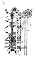
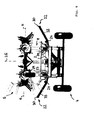
- the haymaking machine 1 advantageously comprises an elongated traveling frame 2, which can be mounted with its front end by a conventional attachment 3 on a tractor, not shown, and by a chassis 4, which can be advantageously arranged on a rear-side portion of the traveling frame 2, on Ground is supported.
- Said hitch 3 may be designed differently and advantageously allow a pivoting of the traveling frame 2 relative to the tractor to an upright axis, so that the running frame 2 can run after the tractor in the manner of a trailer.
- a plurality of rotary rakes 5 are articulated in an even closer manner as hay advertising units, which are rotationally drivable in the working position about approximately upright rotary axes 6 and encircling rake tines, by means of which lying on the ground crop such as grass or hay can be matched, swathed, gezetted or otherwise processed.
- the drive for rotatably driving the rotary rake 5 may be designed differently, for example, include a propeller shaft, possibly with transfer case to drive the rotary rake 5 of a PTO of the tractor forth.
- the raking rotors 5 mentioned here are suspended on a supporting frame 7 which is liftable and pivotable relative to the traveling frame 2.
- the rake 5 are hereby advantageously supported by support wheels 8 and Tastrate on the ground, in the illustrated embodiment under each raking rotary 5 such a support wheel 8 is provided.
- side parts of the support frame 7 are advantageously divided into a plurality of support frame parts which can hinge relative to each other about hinge axes, lying in the working position lying in the direction of travel to allow a corresponding ground adjustment across the width of the device.
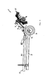
- hinge axis 9 can be pivoted in this case in the excavated position, the entire side part of the support frame 7 with the articulated rotary rakes 5 forward, so that the side parts of the support frame with the articulated rotary rakes 5 extend approximately parallel to the chassis 2 along the running frame forward , see. Fig. 2 to reduce the working width accordingly.
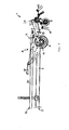
- a central middle part of said supporting frame 7 in this case comprises a rotary rake 5 cross and in the working position to the front of the traveling frame 2 out facing coupling part 10, which serves the articulation of the support frame 7 on the traveling frame 2.
- said coupling part 10 of the supporting frame 7 is articulated to an intermediate frame 11 which extends between the traveling frame 2 and the supporting frame 7.
- said intermediate frame 11 is articulated on the one hand about a first transverse axis 12 pivotally mounted on the driving frame 2, wherein said first transverse axis 12 in the region of the chassis 4, preferably immediately above the chassis 4, so that when digging in the Chassis 2 initiated weight of the rotary rake 5 can be derived directly on the chassis 4.
- said intermediate frame 11 is pivotally connected to the coupling part 10 of the supporting frame 7 about a second horizontal transverse axis 13, so that the intermediate frame 11 and the supporting frame 7 can be bent towards each other, as is a comparison of FIGS FIGS. 4 and 5 shows.
- the lifting / pivoting device 19 for lifting the support frame 7 and the hinged rake 5 hinged thereto in a headland or transport position a Stellaktor 20 between the drive frame 2 and the intermediate frame 11 to pivot the intermediate frame 11 relative to the drive frame 2 and dig out can.
- Said Stellaktor 20 may for example be a hydraulic cylinder, which is articulated on the one hand on the travel frame 2 and a console connected thereto and on the other hand to the intermediate frame 11 and an attached console, in each case spaced from the first transverse axis 12 to a corresponding lever to have.
- the said actuating actuator 20 is first actuated to pivot the entire support frame 7 about said transverse axes lying 12 and 13 upwards, wherein - depending on the work situation - in the Fig. 3 shown headland position can be stopped. Should, however, the haymaking aggregates 5 in the transport position according to Fig. 2 are spent is about the said Hubschwenkvorlegi 19 of the support frame 7 on the in Fig. 4 pivoted headland position shown pivoted upward until the aforementioned hinge axes 9 are approximately upright.
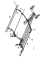
- each of said protective bars 29 has a barrier leg 30 which extends approximately parallel to the traveling frame 2 and is designed to be sufficiently long to laterally cover the haymaking units folded in parallel on the traveling frame 2.
- Said barrier leg 30 may be a bar, a tube or a sheet in the form of a shield or the like, wherein advantageously a longitudinal carrier-like design may be provided, as shown in the figures.
- the barrier leg 30 is mounted on bearing legs 33, which may extend transversely to the direction of travel, on the traveling frame 2 and / or associated holding brackets wherein a pivotable mounting can be provided around horizontal pivot axes 24, as the Fig. 5 clarified.
- the said pivot axis 24 extends for the guard bracket 29 from the longitudinal center plane 25 of the haymaking machine 1 transversely spaced substantially in the direction of travel parallel, so that the transversely projecting guard bracket 29 can be pivoted up and down.
- the said pivot axis 24 may in this case be arranged substantially below the hay-forming aggregates 5 when they are in the transport position, with the said pivot axis 24 in particular being able to extend approximately below the rotary-segment support arms of the rotary gyros.
- the said mechanical actuator 27 may be provided in the region of support surfaces 28 on which the haymaking units 5 can be discontinued in the transport position.
- the aforementioned support surfaces 28 can be provided on a support bracket, which can project transversely obliquely upward from the traveling frame 2 and form at their ends a receiving trough, in which the haymaking units can preferably be discontinued with their guards 34.
- the arrangement and design of said mechanical actuator 27 is made such that project in the lowered initial position of the protective barrier 22, the actuator 27 on the support surface 28 upwards so that when discontinuing the haymaking units 5 of the mechanical actuator 27 with the haymaking units 5 into engagement and can be depressed by these.
- the depression of the mechanical actuators 27 leads to an upward movement of the protective barrier 22 by pivoting about the said pivot axis 24.
- the complete approach of the transport position can again comprise a lowering of the side parts 31 of the support frame 7. If the said side parts 31 are completely folded forwards, the support frame 7 can be tilted a little bit further forward by means of the lifting device 19, whereby the side parts 31 of the support frame 7 projecting forward are lowered to some extent and pressed or pressed against the said actuators 27 Press them down until the support surfaces 28 are completely reached.
- the arrangement can be made such that the protective barriers 22 can extend with their bearing legs 33 in the lowered starting position lying approximately from the support surfaces 28 and slightly underneath to the outside.
- the protective barrier 22 in the lowered starting position, can lie completely below the pivotal path swept over by the side parts 31 and the haymaking units 5 attached thereto, so that the haymaking aggregates 5 are folded forward against the traveling frame 2 without colliding with the protective barriers 22 and driven against the supporting surfaces 28 can be.
- the mechanical Actuator 27 depressed, whereby the bearing legs 33 and thus the entire guard 29 of the protective barriers 22 are each pivoted upwardly, here advantageously the said bearing leg 33 in a tilted from the pivot axes 24 upwardly outward position, preferably at an angle to the horizontal about 30 ° to 60 °, in particular about 30 ° to 45 °, can be brought, as this Fig. 6 shows.
- the pivoting operation is dimensioned such that the protective barriers 22 extend with their barrier legs 30 in height of the rotary rake 5 right and left outside of the rake tines to prevent them from running into the rake tines, see. Fig. 6 ,
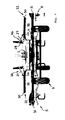
- the Stellaktor 20 In order to perform the mentioned Hubschwenkambaen between working position, headland position and transport position, said Stellaktor 20, the in Fig. 8 have shown training.
- the Stellaktor be designed as an actuating cylinder unit with a plurality of cylinders and pistons, advantageously two mutually separately formed cylinders 40 and 41 can sit on a common piston rod 42, so that the cylinders 40 and 41 each independently relative to the piston rod 42nd can proceed.
- the one cylinder 40 may in this case be formed in a conventional manner as a double-acting cylinder and receive a piston 43 which is axially fixedly connected to the piston rod 42, in particular at its end.
- the piston 43 divides the cylinder 40 in this case into two pressure chambers 46 and 47 arranged on opposite sides of the piston 43, which can each be pressurized via pressure ports 48 and 49 in order to bring about retraction or extension of the piston rod 42 relative to the cylinder 40 ,
- the other cylinder 41 receives two pistons 44 and 45 each slidably, wherein the two pistons 44 and 45 are also arranged displaceably to the piston rod 42, respectively.
- Fig. 8 sits one of the two said piston 44 on the piston rod 42 and is displaceable relative to this.
- the piston rod 42 has at its free end 50, which is located in the interior of the cylinder 41 between the two pistons 44 and 45, an end stop 51 in the form of a thickening, which secures said piston 44 against slipping off of the piston rod 42.
- the said end stop 51 may, for example, in the form of an axially screwed into the piston rod 42 end pin, the head has a larger diameter than the piston rod 42, see.
- Fig. 8
- the other piston 45 which is received in said cylinder 41, is frontally to the free end 50 of the piston rod 42, but without being firmly connected, ie the piston rod 42 can be released from the piston 45 and - Fig. 8 - Move away to the left of the piston 45.
- Said piston 45 is provided to press the end face against the piston rod 42 in order to extend this a little way from the cylinder 41 can.
- the piston 44 is provided to retract the piston rod 42 in the cylinder 41.
- Fig. 8 clarified, can be provided in the cylinder 41 on opposite sides of the two pistons 44 and 45 pressure chambers 52 and 53, to be able to act on the two pistons 44 and 45 in opposite directions.
- said pressure chambers 52 and 53 can be acted upon here by a common pressure port 54 in parallel connected manner to drive the pistons 44 and 45 against each other and thereby clamp the piston rod 42 via said end stop 51 in an intermediate position.
- the cylinder 41 may include between the two pistons 44 and 45 an inwardly projecting end stop 55, for example in the form of a constriction of the cylinder 41, which end stop 55, the travel of the pistons 44 and 45th limited in the cylinder 41 and separated from each other.
- the said end stop 55 is hereby advantageously designed in such a way that the piston rod 42, despite its thickened end portion, ie despite the end stop 51, can move past said cylinder-side end stop 55 in order to be fully extended.
- the other cylinder 40 is pressurized to retract the piston rod 42 in the cylinder 40.
- the geometric relationships are made such that when completely retracted cylinder 40 and held in the aforementioned manner in the intermediate position cylinder 41, the pivot axes 9 approximately upright on the support frame 7 and the side parts 31 - folded by further hydraulic cylinder - forward to the chassis 2 can be, with the working units, in particular the guard bracket 29 still come to lie a little way over the support surfaces 28.
- the cylinder 41 is depressurized, so that the working units can still lower a bit, which is caused by the forward pulling weight of the work units themselves.
- the first cylinder 41st again pressurized, whereby the piston 45 pushes out the piston rod 42 a bit and thereby the work units a bit far raises, so that the work units free from the support surfaces 28 and the protective barrier 22 is lowered again.
- the side parts can be unfolded again and then the support frame 7 are swung back by extending the cylinder 40 until the headland position is reached.
- By re-depressurization of the cylinder 41 of the support frame 7 can be lowered into the working position, and this can be done in a controlled manner by controlling the outflow from the cylinder 41.
Landscapes
- Life Sciences & Earth Sciences (AREA)
- Environmental Sciences (AREA)
- Soil Working Implements (AREA)
- Agricultural Machines (AREA)
Claims (13)
- Machine agricole, de préférence épandeur-faneur combiné à centrifuge multiple, avec un châssis de transport annexable sur un tracteur (2), qui est appuyé au sol via un mécanisme de roulement (4), ainsi qu'au moins un groupe de travail (5) en vue du traitement des aliments et/ou du sol, qui est monté sur un cadre porteur (7), qui est levable par rapport au châssis de transport (2) ensemble avec le groupe de travail (5) à partir d'un dispositif orientable de levage (19) à partir d'une position de travail dans une position de retournement préalable, par ailleurs ainsi que dans une position de transport, le dispositif orientable de levage (19) comprenant une unité à cylindres de réglage (20) avec plusieurs cylindres (40, 41) et plusieurs pistons (43, 44, 45), caractérisée en ce que, dans au moins un des cylindres (41) de l'unité à cylindres de réglage (20), plusieurs pistons (44, 45) sont logés de manière décalable et par rapport à une des tiges de piston contenue de manière décalable dans le cylindre (42), les plusieurs pistons (44, 45) contenant différentes zones de décalage limitées respectivement par rapport à la tige de piston, un des pistons (44) étant assis sur la tige de piston (42) et étant décalable par rapport à celui-ci, et l'autre piston (45) étant prévu afin de presser contre la tige de piston (42), le cylindre (41) présentant une butée finale saillante vers l'intérieur (55) et la tige de piston (42) présentant à son extrémité libre une butée finale (51), qui protège ledit piston (44) contre le glissement hors de la tige de piston (42).
- Machine agricole selon la revendication précédente, le cadre porteur (7) étant articulé de manière oscillante autour d'un axe transversal couché (12 ; 13) sur le châssis de transport (2) et le cadre porteur (7) comprenant au moins une partie latérale dépliante qui est articulée de manière oscillante sur une partie centrale (10) du cadre porteur (7) de sorte que ladite partie latérale est pliable dans la position de travail abaissée autour de charnières d'axe tournées dans le sens de la course et ensemble avec le groupe de travail logé sur la partie latérale vers l'avant sur le châssis de transport (2) avec le groupe de travail (5) logé sur la partie latérale.
- Machine agricole selon la revendication précédente, une surface d'appui (28), notamment une cavité, est prévue pour l'appui d'au moins une partie latérale (31) et/ou d'au moins un groupe de travail logé dessus (5), et la dépose de la partie latérale (31) et/ou du groupe de travail (5) sur la surface d'appui (28) ainsi que la levée de la partie latérale (31) et/ou du groupe de travail (5) de la surface d'appui (28) est commandable par alimentation d'un des deux pistons (45) logés de manière décalable par rapport à la tige de piston (42).
- Machine agricole selon la revendication 2 ou 3, une barrière de protection (22) étant logée de manière mobile sur le châssis de transport (2), qui est mobile entre une position de protection dans laquelle la barrière de protection (22) est disposée transversalement au sens de la marche (23) considéré en amont des groupes de transport (5) se trouvant en position de transport, et une position inactive, dans laquelle les groupes de transport (5) se trouvant en position de transport (5) sont découverts transversalement au sens de la marche (23), la barrière de protection (22) étant actionnable par abaissement des parties latérales rabattues vers l'avant du châssis de transport (7) et amenable dans sa position de protection.
- Machine agricole selon la revendication précédente, l'actionnement de la barrière de protection (22) étant pilotable par alimentation d'un des deux pistons (45) logés de manière coulissante par rapport à la tige de piston (42).
- Machine agricole selon une quelconque des deux revendications précédentes, un actionneur mécanique (27), de préférence sous la forme d'un levier orientable configuré en une bascule avec la barrière de protection, est couplé avec la barrière de protection (22), ainsi que disposé et agencé de sorte, que l'actionneur (27) est amenable en prise avec une pièce de groupe de travail et/ou une pièce de cadre porteur, lorsqu'au moins un groupe de travail (5) est déplacé vers sa position de transport et/ou parvient en position de transport.
- Machine agricole selon une quelconque des revendications précédentes, les trajectoires de décalage des deux pistons (44, 45) logés de dans le même cylindre (41) étant agencées sans chevauchement sur et/ou par rapport à la tige de piston (42).
- Machine agricole selon une quelconque des revendications précédentes, deux parcours de réglage de la tige de piston (42) indépendants l'un de l'autre étant générables par rapport audit cylindre, par les deux pistons (44, 45) intégrés dans le même cylindre (41) notamment de sorte que, par l'alimentation d'un premier piston (44), indépendamment de l'alimentation de l'autre piston, un premier parcours de réglage, et par l'alimentation de l'autre piston (45), indépendamment de l'alimentation dudit piston précité (44), un autre parcours de réglage est générable.
- Machine agricole selon la revendication précédente, les deux parcours de réglage générables par les deux pistons (44, 45) logés dans le même cylindre (41) étant de longueur différente, un parcours de réglage s'élevant de préférence à moins d'un tiers de l'autre parcours de réglage.
- Machine agricole selon une quelconque des revendications précédentes, un des deux pistons (44) logés dans le même cylindre (41) étant prévu pour la sortie de la tige de piston (42) et l'autre des deux pistons (45) logés de dans le même cylindre (41) étant prévu pour l'entrée de la tige de piston (42) dans ledit cylindre (41).
- Machine agricole selon une quelconque des revendications précédentes, le cylindre, dans lequel sont logés les plusieurs pistons (44, 45) possédant entre les pistons (44, 45) au moins une butée saillante radialement vers l'intérieur, qui limite les parcours de réglage des pistons (44, 45) et les sépare l'un de l'autre, ladite butée étant agencée de sorte que la tige de piston (42) est apte à passer avec son extrémité libre devant ladite butée.
- Machine agricole selon une quelconque des revendications précédentes, le cylindre (41) logeant les plusieurs pistons (44, 45) possédant deux chambres de compression, sur des côtés détournés l'un de l'autre des pistons (44, 45) les deux chambres de compression branchées de préférence en parallèle à partir d'une conduite de compression commune étant alimentables en pression de sorte que la tige de piston (42) est fixée et/ou serrée dans une position intermédiaire par les deux pistons (44, 45) dans leur position finale.
- Machine agricole selon une quelconque des revendications précédentes, un piston alimentable bilatéralement étant prévu dans au moins un des cylindres (40), qui est fixé de préférence axialement et de manière non décalable sur la tige de piston, et/ou deux cylindres (40, 41) étant assis sur une tige de piston commune (42), ladite tige de piston (42) étant entrable et sortable par deux mouvements de réglage exécutables indépendamment l'un de l'autre par rapport à un cylindre (40) et étant entrable et sortable par rapport à l'autre cylindre (41) et/ou un des cylindres étant prévu pour un parcours de réglage entre la position de retournement et la position de transport et un autre cylindre étant prévu pour un mouvement de réglage entre la position de travail et la position de retournement et pour un parcours de réglage adjacent à la position de transport.
Priority Applications (2)
| Application Number | Priority Date | Filing Date | Title |
|---|---|---|---|
| SI201230426T SI2591663T1 (sl) | 2011-11-09 | 2012-11-07 | Poljedelski stroj |
| PL12007573T PL2591663T3 (pl) | 2011-11-09 | 2012-11-07 | Maszyna rolnicza |
Applications Claiming Priority (1)
| Application Number | Priority Date | Filing Date | Title |
|---|---|---|---|
| DE202011107678U DE202011107678U1 (de) | 2011-11-09 | 2011-11-09 | Landwirtschaftliche Maschine |
Publications (2)
| Publication Number | Publication Date |
|---|---|
| EP2591663A1 EP2591663A1 (fr) | 2013-05-15 |
| EP2591663B1 true EP2591663B1 (fr) | 2015-10-14 |
Family
ID=47225889
Family Applications (1)
| Application Number | Title | Priority Date | Filing Date |
|---|---|---|---|
| EP12007573.4A Active EP2591663B1 (fr) | 2011-11-09 | 2012-11-07 | Machine agricole |
Country Status (5)
| Country | Link |
|---|---|
| EP (1) | EP2591663B1 (fr) |
| DE (1) | DE202011107678U1 (fr) |
| DK (1) | DK2591663T3 (fr) |
| PL (1) | PL2591663T3 (fr) |
| SI (1) | SI2591663T1 (fr) |
Families Citing this family (2)
| Publication number | Priority date | Publication date | Assignee | Title |
|---|---|---|---|---|
| GB201321992D0 (en) * | 2013-12-12 | 2014-01-29 | Fella Werke Gmbh | Agricultural working tool with transport configuration |
| DE202020103922U1 (de) | 2020-07-07 | 2021-10-08 | Pöttinger Landtechnik Gmbh | Landwirtschaftliche Maschine |
Family Cites Families (3)
| Publication number | Priority date | Publication date | Assignee | Title |
|---|---|---|---|---|
| NL1014703C2 (nl) | 2000-03-21 | 2001-09-25 | Fountain Technologies B V I O | Werkwijze en inrichting voor het vervaardigen van kunststof producten met verschillende wandstructuren. |
| NL1031852C2 (nl) | 2006-05-22 | 2007-11-23 | Maasland Nv | Landbouwmachine. |
| NL1036115C (nl) * | 2008-10-27 | 2010-04-28 | Lely Patent Nv | Landbouwmachine. |
-
2011
- 2011-11-09 DE DE202011107678U patent/DE202011107678U1/de not_active Expired - Lifetime
-
2012
- 2012-11-07 SI SI201230426T patent/SI2591663T1/sl unknown
- 2012-11-07 DK DK12007573.4T patent/DK2591663T3/en active
- 2012-11-07 EP EP12007573.4A patent/EP2591663B1/fr active Active
- 2012-11-07 PL PL12007573T patent/PL2591663T3/pl unknown
Also Published As
| Publication number | Publication date |
|---|---|
| PL2591663T3 (pl) | 2016-04-29 |
| DE202011107678U1 (de) | 2013-02-13 |
| EP2591663A1 (fr) | 2013-05-15 |
| DK2591663T3 (en) | 2016-01-11 |
| SI2591663T1 (sl) | 2016-03-31 |
Similar Documents
| Publication | Publication Date | Title |
|---|---|---|
| EP0872170B1 (fr) | Machine de fenaison | |
| EP3122168B1 (fr) | Appareil de travail du sol comprenant un dispositif d'étrillage et d'aplanissement | |
| EP3704928B1 (fr) | Machine de récolte et procédé de récolte au moyen d'une machine de récolte | |
| EP1095555B1 (fr) | Machine de fenaison | |
| EP1163830B1 (fr) | Appareil agricole tracté | |
| EP2591653B1 (fr) | Machine de fenaison | |
| EP2591663B1 (fr) | Machine agricole | |
| EP1488685B1 (fr) | Machine de fenaison | |
| DE202018106434U1 (de) | Landwirtschaftliches Anbaugerät | |
| EP3804493B1 (fr) | Faucheuse dotée d'un dispositif de protection et engin de travaux doté d'une telle faucheuse | |
| DE29818457U1 (de) | Landwirtschaftliche Bearbeitungsmaschine | |
| EP0937382B1 (fr) | Faneuse rotative | |
| EP2591662B1 (fr) | Faneuse | |
| DE9305014U1 (de) | Heuwerbungsmaschine | |
| EP3205194B1 (fr) | Appareil agricole comprenant un châssis de machine repliable | |
| EP0288416B1 (fr) | Machine de fenaison | |
| DE202008014367U1 (de) | Heuwerbungsmaschine | |
| EP3590322B1 (fr) | Appareil de travail agricole | |
| EP4278875B1 (fr) | Outil pour la culture des champs | |
| DE20219242U1 (de) | Heuwerbungsmaschine | |
| DE202020103922U1 (de) | Landwirtschaftliche Maschine | |
| EP4122304B1 (fr) | Machine de travail agricole | |
| EP3058804A1 (fr) | Faneuse | |
| EP1597953B1 (fr) | Machine agricole | |
| EP3791706B1 (fr) | Machine de travail agricole pourvue d'outil de travail réglable en hauteur |
Legal Events
| Date | Code | Title | Description |
|---|---|---|---|
| PUAI | Public reference made under article 153(3) epc to a published international application that has entered the european phase |
Free format text: ORIGINAL CODE: 0009012 |
|
| AK | Designated contracting states |
Kind code of ref document: A1 Designated state(s): AL AT BE BG CH CY CZ DE DK EE ES FI FR GB GR HR HU IE IS IT LI LT LU LV MC MK MT NL NO PL PT RO RS SE SI SK SM TR |
|
| AX | Request for extension of the european patent |
Extension state: BA ME |
|
| 17P | Request for examination filed |
Effective date: 20131113 |
|
| 17Q | First examination report despatched |
Effective date: 20140122 |
|
| GRAP | Despatch of communication of intention to grant a patent |
Free format text: ORIGINAL CODE: EPIDOSNIGR1 |
|
| INTG | Intention to grant announced |
Effective date: 20150608 |
|
| GRAS | Grant fee paid |
Free format text: ORIGINAL CODE: EPIDOSNIGR3 |
|
| GRAA | (expected) grant |
Free format text: ORIGINAL CODE: 0009210 |
|
| AK | Designated contracting states |
Kind code of ref document: B1 Designated state(s): AL AT BE BG CH CY CZ DE DK EE ES FI FR GB GR HR HU IE IS IT LI LT LU LV MC MK MT NL NO PL PT RO RS SE SI SK SM TR |
|
| REG | Reference to a national code |
Ref country code: GB Ref legal event code: FG4D Free format text: NOT ENGLISH |
|
| REG | Reference to a national code |
Ref country code: AT Ref legal event code: REF Ref document number: 754397 Country of ref document: AT Kind code of ref document: T Effective date: 20151015 Ref country code: CH Ref legal event code: EP |
|
| REG | Reference to a national code |
Ref country code: IE Ref legal event code: FG4D Free format text: LANGUAGE OF EP DOCUMENT: GERMAN |
|
| REG | Reference to a national code |
Ref country code: FR Ref legal event code: PLFP Year of fee payment: 4 |
|
| REG | Reference to a national code |
Ref country code: DE Ref legal event code: R096 Ref document number: 502012004884 Country of ref document: DE |
|
| REG | Reference to a national code |
Ref country code: DK Ref legal event code: T3 Effective date: 20160107 |
|
| REG | Reference to a national code |
Ref country code: NL Ref legal event code: FP |
|
| PGFP | Annual fee paid to national office [announced via postgrant information from national office to epo] |
Ref country code: IE Payment date: 20151124 Year of fee payment: 4 |
|
| REG | Reference to a national code |
Ref country code: LT Ref legal event code: MG4D |
|
| PG25 | Lapsed in a contracting state [announced via postgrant information from national office to epo] |
Ref country code: ES Free format text: LAPSE BECAUSE OF FAILURE TO SUBMIT A TRANSLATION OF THE DESCRIPTION OR TO PAY THE FEE WITHIN THE PRESCRIBED TIME-LIMIT Effective date: 20151014 Ref country code: NO Free format text: LAPSE BECAUSE OF FAILURE TO SUBMIT A TRANSLATION OF THE DESCRIPTION OR TO PAY THE FEE WITHIN THE PRESCRIBED TIME-LIMIT Effective date: 20160114 Ref country code: IS Free format text: LAPSE BECAUSE OF FAILURE TO SUBMIT A TRANSLATION OF THE DESCRIPTION OR TO PAY THE FEE WITHIN THE PRESCRIBED TIME-LIMIT Effective date: 20160214 Ref country code: LT Free format text: LAPSE BECAUSE OF FAILURE TO SUBMIT A TRANSLATION OF THE DESCRIPTION OR TO PAY THE FEE WITHIN THE PRESCRIBED TIME-LIMIT Effective date: 20151014 Ref country code: HR Free format text: LAPSE BECAUSE OF FAILURE TO SUBMIT A TRANSLATION OF THE DESCRIPTION OR TO PAY THE FEE WITHIN THE PRESCRIBED TIME-LIMIT Effective date: 20151014 |
|
| PG25 | Lapsed in a contracting state [announced via postgrant information from national office to epo] |
Ref country code: GR Free format text: LAPSE BECAUSE OF FAILURE TO SUBMIT A TRANSLATION OF THE DESCRIPTION OR TO PAY THE FEE WITHIN THE PRESCRIBED TIME-LIMIT Effective date: 20160115 Ref country code: FI Free format text: LAPSE BECAUSE OF FAILURE TO SUBMIT A TRANSLATION OF THE DESCRIPTION OR TO PAY THE FEE WITHIN THE PRESCRIBED TIME-LIMIT Effective date: 20151014 Ref country code: RS Free format text: LAPSE BECAUSE OF FAILURE TO SUBMIT A TRANSLATION OF THE DESCRIPTION OR TO PAY THE FEE WITHIN THE PRESCRIBED TIME-LIMIT Effective date: 20151014 Ref country code: SE Free format text: LAPSE BECAUSE OF FAILURE TO SUBMIT A TRANSLATION OF THE DESCRIPTION OR TO PAY THE FEE WITHIN THE PRESCRIBED TIME-LIMIT Effective date: 20151014 Ref country code: PT Free format text: LAPSE BECAUSE OF FAILURE TO SUBMIT A TRANSLATION OF THE DESCRIPTION OR TO PAY THE FEE WITHIN THE PRESCRIBED TIME-LIMIT Effective date: 20160215 Ref country code: LV Free format text: LAPSE BECAUSE OF FAILURE TO SUBMIT A TRANSLATION OF THE DESCRIPTION OR TO PAY THE FEE WITHIN THE PRESCRIBED TIME-LIMIT Effective date: 20151014 |
|
| RAP2 | Party data changed (patent owner data changed or rights of a patent transferred) |
Owner name: POETTINGER LANDTECHNIK GMBH |
|
| REG | Reference to a national code |
Ref country code: CH Ref legal event code: PL |
|
| REG | Reference to a national code |
Ref country code: DE Ref legal event code: R097 Ref document number: 502012004884 Country of ref document: DE |
|
| PG25 | Lapsed in a contracting state [announced via postgrant information from national office to epo] |
Ref country code: LI Free format text: LAPSE BECAUSE OF NON-PAYMENT OF DUE FEES Effective date: 20151130 Ref country code: MC Free format text: LAPSE BECAUSE OF FAILURE TO SUBMIT A TRANSLATION OF THE DESCRIPTION OR TO PAY THE FEE WITHIN THE PRESCRIBED TIME-LIMIT Effective date: 20151014 Ref country code: CZ Free format text: LAPSE BECAUSE OF FAILURE TO SUBMIT A TRANSLATION OF THE DESCRIPTION OR TO PAY THE FEE WITHIN THE PRESCRIBED TIME-LIMIT Effective date: 20151014 Ref country code: CH Free format text: LAPSE BECAUSE OF NON-PAYMENT OF DUE FEES Effective date: 20151130 |
|
| PLBE | No opposition filed within time limit |
Free format text: ORIGINAL CODE: 0009261 |
|
| STAA | Information on the status of an ep patent application or granted ep patent |
Free format text: STATUS: NO OPPOSITION FILED WITHIN TIME LIMIT |
|
| PG25 | Lapsed in a contracting state [announced via postgrant information from national office to epo] |
Ref country code: SK Free format text: LAPSE BECAUSE OF FAILURE TO SUBMIT A TRANSLATION OF THE DESCRIPTION OR TO PAY THE FEE WITHIN THE PRESCRIBED TIME-LIMIT Effective date: 20151014 Ref country code: SM Free format text: LAPSE BECAUSE OF FAILURE TO SUBMIT A TRANSLATION OF THE DESCRIPTION OR TO PAY THE FEE WITHIN THE PRESCRIBED TIME-LIMIT Effective date: 20151014 Ref country code: EE Free format text: LAPSE BECAUSE OF FAILURE TO SUBMIT A TRANSLATION OF THE DESCRIPTION OR TO PAY THE FEE WITHIN THE PRESCRIBED TIME-LIMIT Effective date: 20151014 Ref country code: RO Free format text: LAPSE BECAUSE OF FAILURE TO SUBMIT A TRANSLATION OF THE DESCRIPTION OR TO PAY THE FEE WITHIN THE PRESCRIBED TIME-LIMIT Effective date: 20151014 |
|
| 26N | No opposition filed |
Effective date: 20160715 |
|
| REG | Reference to a national code |
Ref country code: FR Ref legal event code: PLFP Year of fee payment: 5 |
|
| PG25 | Lapsed in a contracting state [announced via postgrant information from national office to epo] |
Ref country code: HU Free format text: LAPSE BECAUSE OF FAILURE TO SUBMIT A TRANSLATION OF THE DESCRIPTION OR TO PAY THE FEE WITHIN THE PRESCRIBED TIME-LIMIT; INVALID AB INITIO Effective date: 20121107 Ref country code: BG Free format text: LAPSE BECAUSE OF FAILURE TO SUBMIT A TRANSLATION OF THE DESCRIPTION OR TO PAY THE FEE WITHIN THE PRESCRIBED TIME-LIMIT Effective date: 20151014 |
|
| PG25 | Lapsed in a contracting state [announced via postgrant information from national office to epo] |
Ref country code: CY Free format text: LAPSE BECAUSE OF FAILURE TO SUBMIT A TRANSLATION OF THE DESCRIPTION OR TO PAY THE FEE WITHIN THE PRESCRIBED TIME-LIMIT Effective date: 20151014 |
|
| GBPC | Gb: european patent ceased through non-payment of renewal fee |
Effective date: 20161107 |
|
| PG25 | Lapsed in a contracting state [announced via postgrant information from national office to epo] |
Ref country code: BE Free format text: LAPSE BECAUSE OF NON-PAYMENT OF DUE FEES Effective date: 20151130 |
|
| REG | Reference to a national code |
Ref country code: IE Ref legal event code: MM4A |
|
| PG25 | Lapsed in a contracting state [announced via postgrant information from national office to epo] |
Ref country code: MT Free format text: LAPSE BECAUSE OF FAILURE TO SUBMIT A TRANSLATION OF THE DESCRIPTION OR TO PAY THE FEE WITHIN THE PRESCRIBED TIME-LIMIT Effective date: 20151014 |
|
| REG | Reference to a national code |
Ref country code: FR Ref legal event code: PLFP Year of fee payment: 6 |
|
| PG25 | Lapsed in a contracting state [announced via postgrant information from national office to epo] |
Ref country code: GB Free format text: LAPSE BECAUSE OF NON-PAYMENT OF DUE FEES Effective date: 20161107 Ref country code: LU Free format text: LAPSE BECAUSE OF NON-PAYMENT OF DUE FEES Effective date: 20151107 Ref country code: IE Free format text: LAPSE BECAUSE OF NON-PAYMENT OF DUE FEES Effective date: 20161107 |
|
| PG25 | Lapsed in a contracting state [announced via postgrant information from national office to epo] |
Ref country code: MK Free format text: LAPSE BECAUSE OF FAILURE TO SUBMIT A TRANSLATION OF THE DESCRIPTION OR TO PAY THE FEE WITHIN THE PRESCRIBED TIME-LIMIT Effective date: 20151014 Ref country code: TR Free format text: LAPSE BECAUSE OF FAILURE TO SUBMIT A TRANSLATION OF THE DESCRIPTION OR TO PAY THE FEE WITHIN THE PRESCRIBED TIME-LIMIT Effective date: 20151014 |
|
| REG | Reference to a national code |
Ref country code: FR Ref legal event code: PLFP Year of fee payment: 7 |
|
| PG25 | Lapsed in a contracting state [announced via postgrant information from national office to epo] |
Ref country code: AL Free format text: LAPSE BECAUSE OF FAILURE TO SUBMIT A TRANSLATION OF THE DESCRIPTION OR TO PAY THE FEE WITHIN THE PRESCRIBED TIME-LIMIT Effective date: 20151014 |
|
| PGFP | Annual fee paid to national office [announced via postgrant information from national office to epo] |
Ref country code: IT Payment date: 20181029 Year of fee payment: 10 |
|
| PGFP | Annual fee paid to national office [announced via postgrant information from national office to epo] |
Ref country code: AT Payment date: 20191009 Year of fee payment: 8 |
|
| PG25 | Lapsed in a contracting state [announced via postgrant information from national office to epo] |
Ref country code: IT Free format text: LAPSE BECAUSE OF NON-PAYMENT OF DUE FEES Effective date: 20191107 |
|
| REG | Reference to a national code |
Ref country code: AT Ref legal event code: MM01 Ref document number: 754397 Country of ref document: AT Kind code of ref document: T Effective date: 20201107 |
|
| PG25 | Lapsed in a contracting state [announced via postgrant information from national office to epo] |
Ref country code: AT Free format text: LAPSE BECAUSE OF NON-PAYMENT OF DUE FEES Effective date: 20201107 |
|
| PGFP | Annual fee paid to national office [announced via postgrant information from national office to epo] |
Ref country code: NL Payment date: 20221114 Year of fee payment: 11 |
|
| PGFP | Annual fee paid to national office [announced via postgrant information from national office to epo] |
Ref country code: PL Payment date: 20221018 Year of fee payment: 11 |
|
| P01 | Opt-out of the competence of the unified patent court (upc) registered |
Effective date: 20230613 |
|
| REG | Reference to a national code |
Ref country code: NL Ref legal event code: MM Effective date: 20231201 |
|
| PG25 | Lapsed in a contracting state [announced via postgrant information from national office to epo] |
Ref country code: NL Free format text: LAPSE BECAUSE OF NON-PAYMENT OF DUE FEES Effective date: 20231201 |
|
| PG25 | Lapsed in a contracting state [announced via postgrant information from national office to epo] |
Ref country code: NL Free format text: LAPSE BECAUSE OF NON-PAYMENT OF DUE FEES Effective date: 20231201 |
|
| PG25 | Lapsed in a contracting state [announced via postgrant information from national office to epo] |
Ref country code: PL Free format text: LAPSE BECAUSE OF NON-PAYMENT OF DUE FEES Effective date: 20231107 |
|
| PGFP | Annual fee paid to national office [announced via postgrant information from national office to epo] |
Ref country code: DE Payment date: 20251118 Year of fee payment: 14 |
|
| PGFP | Annual fee paid to national office [announced via postgrant information from national office to epo] |
Ref country code: DK Payment date: 20251125 Year of fee payment: 14 |
|
| PGFP | Annual fee paid to national office [announced via postgrant information from national office to epo] |
Ref country code: FR Payment date: 20251126 Year of fee payment: 14 |
|
| PGFP | Annual fee paid to national office [announced via postgrant information from national office to epo] |
Ref country code: SI Payment date: 20251028 Year of fee payment: 14 |