EP2591328B1 - Adiabatisches erfassungskalorimeter - Google Patents
Adiabatisches erfassungskalorimeter Download PDFInfo
- Publication number
- EP2591328B1 EP2591328B1 EP11749073.0A EP11749073A EP2591328B1 EP 2591328 B1 EP2591328 B1 EP 2591328B1 EP 11749073 A EP11749073 A EP 11749073A EP 2591328 B1 EP2591328 B1 EP 2591328B1
- Authority
- EP
- European Patent Office
- Prior art keywords
- sample
- shield
- temperature
- peltier element
- enthalpy
- Prior art date
- Legal status (The legal status is an assumption and is not a legal conclusion. Google has not performed a legal analysis and makes no representation as to the accuracy of the status listed.)
- Active
Links
- 230000007704 transition Effects 0.000 claims description 38
- 238000010438 heat treatment Methods 0.000 claims description 34
- 238000001816 cooling Methods 0.000 claims description 27
- 238000005259 measurement Methods 0.000 claims description 15
- 239000007787 solid Substances 0.000 claims description 13
- 239000004973 liquid crystal related substance Substances 0.000 claims description 12
- 239000007788 liquid Substances 0.000 claims description 11
- 238000000034 method Methods 0.000 claims description 8
- 239000000463 material Substances 0.000 claims description 5
- BASFCYQUMIYNBI-UHFFFAOYSA-N platinum Chemical compound [Pt] BASFCYQUMIYNBI-UHFFFAOYSA-N 0.000 claims description 4
- 238000000926 separation method Methods 0.000 claims description 3
- 230000005493 condensed matter Effects 0.000 claims description 2
- 238000012544 monitoring process Methods 0.000 claims description 2
- 229910052697 platinum Inorganic materials 0.000 claims description 2
- 210000000170 cell membrane Anatomy 0.000 claims 1
- 238000004519 manufacturing process Methods 0.000 claims 1
- 239000012071 phase Substances 0.000 description 29
- 238000001623 adiabatic scanning calorimetry Methods 0.000 description 9
- 238000000113 differential scanning calorimetry Methods 0.000 description 8
- POOSGDOYLQNASK-UHFFFAOYSA-N tetracosane Chemical compound CCCCCCCCCCCCCCCCCCCCCCCC POOSGDOYLQNASK-UHFFFAOYSA-N 0.000 description 8
- JIXOHNQBTLYMHT-UHFFFAOYSA-N 2-octyl-6-phenylbenzonitrile Chemical group CCCCCCCCC1=CC=CC(C=2C=CC=CC=2)=C1C#N JIXOHNQBTLYMHT-UHFFFAOYSA-N 0.000 description 6
- 239000004990 Smectic liquid crystal Substances 0.000 description 6
- 239000010409 thin film Substances 0.000 description 6
- 238000007707 calorimetry Methods 0.000 description 5
- 239000013078 crystal Substances 0.000 description 5
- 230000004069 differentiation Effects 0.000 description 4
- 230000004048 modification Effects 0.000 description 4
- 238000013459 approach Methods 0.000 description 3
- 230000008859 change Effects 0.000 description 3
- 239000011261 inert gas Substances 0.000 description 3
- 239000007791 liquid phase Substances 0.000 description 3
- 229910052751 metal Inorganic materials 0.000 description 3
- 239000002184 metal Substances 0.000 description 3
- 238000012986 modification Methods 0.000 description 3
- 239000004593 Epoxy Substances 0.000 description 2
- 150000001335 aliphatic alkanes Chemical class 0.000 description 2
- 238000013461 design Methods 0.000 description 2
- 238000001514 detection method Methods 0.000 description 2
- 238000011161 development Methods 0.000 description 2
- 230000018109 developmental process Effects 0.000 description 2
- 239000007789 gas Substances 0.000 description 2
- 238000011835 investigation Methods 0.000 description 2
- 239000006072 paste Substances 0.000 description 2
- 230000035945 sensitivity Effects 0.000 description 2
- 238000005476 soldering Methods 0.000 description 2
- 239000002966 varnish Substances 0.000 description 2
- RYGMFSIKBFXOCR-UHFFFAOYSA-N Copper Chemical compound [Cu] RYGMFSIKBFXOCR-UHFFFAOYSA-N 0.000 description 1
- PEDCQBHIVMGVHV-UHFFFAOYSA-N Glycerine Chemical compound OCC(O)CO PEDCQBHIVMGVHV-UHFFFAOYSA-N 0.000 description 1
- BQCADISMDOOEFD-UHFFFAOYSA-N Silver Chemical compound [Ag] BQCADISMDOOEFD-UHFFFAOYSA-N 0.000 description 1
- 230000006978 adaptation Effects 0.000 description 1
- 239000004411 aluminium Substances 0.000 description 1
- 229910052782 aluminium Inorganic materials 0.000 description 1
- XAGFODPZIPBFFR-UHFFFAOYSA-N aluminium Chemical compound [Al] XAGFODPZIPBFFR-UHFFFAOYSA-N 0.000 description 1
- 238000011088 calibration curve Methods 0.000 description 1
- 238000012512 characterization method Methods 0.000 description 1
- 239000004020 conductor Substances 0.000 description 1
- 238000010276 construction Methods 0.000 description 1
- 239000010949 copper Substances 0.000 description 1
- 229910052802 copper Inorganic materials 0.000 description 1
- 238000007405 data analysis Methods 0.000 description 1
- 239000010408 film Substances 0.000 description 1
- 230000004907 flux Effects 0.000 description 1
- 238000010348 incorporation Methods 0.000 description 1
- 239000011810 insulating material Substances 0.000 description 1
- 230000007774 longterm Effects 0.000 description 1
- 150000002739 metals Chemical class 0.000 description 1
- 239000000203 mixture Substances 0.000 description 1
- 238000005086 pumping Methods 0.000 description 1
- 230000005855 radiation Effects 0.000 description 1
- 239000004065 semiconductor Substances 0.000 description 1
- 239000004332 silver Substances 0.000 description 1
- 229910052709 silver Inorganic materials 0.000 description 1
- 238000001179 sorption measurement Methods 0.000 description 1
- 230000000087 stabilizing effect Effects 0.000 description 1
- 238000004781 supercooling Methods 0.000 description 1
Images


Classifications
-
- G—PHYSICS
- G01—MEASURING; TESTING
- G01K—MEASURING TEMPERATURE; MEASURING QUANTITY OF HEAT; THERMALLY-SENSITIVE ELEMENTS NOT OTHERWISE PROVIDED FOR
- G01K17/00—Measuring quantity of heat
-
- G—PHYSICS
- G01—MEASURING; TESTING
- G01K—MEASURING TEMPERATURE; MEASURING QUANTITY OF HEAT; THERMALLY-SENSITIVE ELEMENTS NOT OTHERWISE PROVIDED FOR
- G01K17/00—Measuring quantity of heat
- G01K17/04—Calorimeters using compensation methods, i.e. where the absorbed or released quantity of heat to be measured is compensated by a measured quantity of heating or cooling
-
- G—PHYSICS
- G01—MEASURING; TESTING
- G01N—INVESTIGATING OR ANALYSING MATERIALS BY DETERMINING THEIR CHEMICAL OR PHYSICAL PROPERTIES
- G01N25/00—Investigating or analyzing materials by the use of thermal means
- G01N25/20—Investigating or analyzing materials by the use of thermal means by investigating the development of heat, i.e. calorimetry, e.g. by measuring specific heat, by measuring thermal conductivity
- G01N25/48—Investigating or analyzing materials by the use of thermal means by investigating the development of heat, i.e. calorimetry, e.g. by measuring specific heat, by measuring thermal conductivity on solution, sorption, or a chemical reaction not involving combustion or catalytic oxidation
- G01N25/4806—Details not adapted to a particular type of sample
- G01N25/4826—Details not adapted to a particular type of sample concerning the heating or cooling arrangements
- G01N25/4833—Details not adapted to a particular type of sample concerning the heating or cooling arrangements specially adapted for temperature scanning
Definitions
- the present invention generally relates to an adiabatic scanning calorimeter for simultaneous measurements of the temperature dependence of heat capacity and enthalpy of liquids and solids and phase transitions therein. Moreover, the invention allows for an accurate separation between pretransitional enthalpy variations and true latent heats at first-order or weakly first-order phase transitions. In addition, the invention relates to calorimeters for controlling temperature differences and heat fluxes in different modes of operation.
- DSC differential scanning calorimetry
- 2,3 scanning transitiometry 4-6 and modulation techniques like ac calorimetry 7,8
- the 3 ⁇ method 9 and more recently photoacoustic and photopyroelectric techniques 10 Peltier ac and Peltier tip calorimetry, 11,12 Peltier heat-flow and modulated bath ac calorimetry. 13,14
- the setup is conceptually similar to the (power compensated) differential scanning calorimeter.
- the DSC is a very useful for many (material science) applications when the (total) energy change of a transition is of greater interest than the detailed form of the specific heat or enthalpy curve (near phase transitions).
- a commercial DSC (or modulated DSC) generally does not yield accurate absolute values of specific heat and by using high scanning rates (typically above 0.2 Ks -1 to have a reasonable sensitivity) quite often operates out of thermodynamic equilibrium, in particular near fluctuations dominated phase transitions.
- the present invention eliminates these problems completely by inserting between the sample and the shield a very sensitive (of the order of 0.1 V/K) semiconductor materials based Peltier element (PE), either a Peltier cooler or Peltier thermogenerator, which are commercially available.
- PE Peltier element
- the ⁇ K sensitivity of the PE for temperature differences allows in combination with proper servo systems (hardware or software) to maintain almost perfect equality of the sample and shield temperatures in the heating mode.
- a preset temperature difference between sample and shield can be kept constant with equal resolution.
- the present invention solves the problems of the related art by introducing an adiabatic scanning calorimeter for simultaneous measurements of heat capacity and enthalpy over broad temperature ranges (typically 100K) in different accurately controlled scanning modes by introducing sensitive Peltier elements in the temperature and scanning rate control of different stages in the calorimeter.
- the invention is broadly drawn to eliminate problems with keeping temperature differences between an investigated sample and a surrounding thermal (adiabatic) shield zero or at a preset fixed value during temperature scanning over broad ranges without approximations and lengthy calibrations inherently associated in using different separate temperature sensors as in the previous art.
- the calorimeter In one aspect of the invention it is possible in the two principal (heating or cooling) scanning modes of operation of the calorimeter to simultaneously arrive at accurate and detailed information on the temperature dependence of the heat capacity and enthalpy by delivering constant heating or cooling power to the sample and by Peltier element based control of the thermal shield.
- the thus operated calorimeter allows for a clear separation of pretransitional enthalpy increases and true latent heats at (weakly) first-order transitions and precise characterization of heat capacity anomalies at second-order phase transitions.
- An other aspect of the calorimeter is the possibility to operate, besides in the above mentioned principal modes, in several other more conventional or unconventional ways, as e.g. in DSC-like constant heating or cooling rate modes, as a classical (Nernst-type) heat pulse step calorimeter, in the two principal modes without sensor or heater attached to the sample, or in modulated heating or cooling power modes, or in purely ac heating or cooling modes.
- Still another aspect of the invention is the versatility in arranging the sample (liquid or solid) configurations to adapt to the chosen scanning modes.
- the full implementation of programmable electronic measurement and control equipment connected to a personal computer allows full software choice of operational modes, long term independent operation and extensive data analysis.
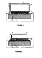
- a Peltier element based adiabatic scanning calorimeter for simultaneous measurements of heat capacity and enthalpy is illustrated in figure 1 , and partly in figure 2 .
- a sample [1] is contained in a good thermal conducting (e.g. metal) sample holder [2] containing a heating element [3] (e.g. heating wire or thin film heater) and a sensitive temperature sensor [4] (e.g. a thermistor or a Platinum resistance thermometer).
- the Peltier element is arranged to geometrically position between said at least one plate that contacts the sample holder and at least one plate that contacts the shield for instance the shield bottom [8].
- the sample holder [2] is positioned in good thermal contact with the top plate [5] of the Peltier element [6].
- the sample holder is positioned in good thermal contact with the top plate [5] of the Peltier element [6].
- Good thermal contact can e.g. be achieved by soldering, with good thermal conductive varnish, epoxy or paste. For ease of removal of the sample holder thermal paste can preferentially be used.
- the base plate [7] of the Peltier element is also positioned in good thermal contact with the shield bottom [8]. Good thermal contact can e.g.
- the shield top [9] is in very good thermal contact with the shield bottom [8] by a sufficiently long screw thread.
- the shield top [9] has a heater [10] incorporated in the wall.
- a small hole [11] in the shield is present for possible evacuation or as inert gas inlet.
- the shield also has its own temperature sensor [12].
- the shield bottom also has the necessary electrical feed-troughs [13].
- the first shield bottom [8] rests on the bottom [14] of a second shield and is thermally insulated by typically three thin rods or tubes [15] with very high thermal resistances.
- the second shield bottom [14] contains also a temperature sensor [16] and (multipin) electrical feed-troughs [17].
- a heater [19] is also incorporated in the top part of the second shield [18] . It also as a few holes [20] for evacuation purposes or as inert gas inlets.
- the top [18] and bottom [14] of the second shield are in very good thermal contact by means of a sufficiently long screw thread.
- the second shield bottom rests on the bottom [21] of a third shield (outer can) and is thermally insulated by typically three thin rods or tubes [22] with very high thermal resistances.
- the third shield bottom [21] contains vacuum-tight multipin electrical feed-troughs [23].
- the top [24] of the third outer shield and bottom [21] can be vacuum-tightly closed by means of screws and an O-ring [25] in a groove of the bottom [21].
- the third shield top [24] (or alternatively shield bottom [21]) contains a connecting tube [26] to a vacuum pumping system or an inert gas inlet system.
- the bottom of the third (outer) shield [21] is supported by typically three thin rods or tubes [27] with very high thermal resistance.
- the calorimeter allows the calorimeter to be place on a table top and if desired surrounded with insulating material.
- the calorimeter is placed in a temperature controlled chamber (stability around ⁇ 0.1 K) equipped with heating and cooling units allowing measurements between -60 °C and 150 °C.
- Lower cryogenic temperatures e. g. to -200 °C
- Proper choice of Peltier elements allows temperatures up to above 200 °C.
- FIG. 2 gives a more detailed view of a possible sample cell [2] with heater [3] and temperature sensor [4] and with inside a sample [1] (typically a liquid), on top of the top plate [5] of the Peltier element [6].
- the bottom plate [7] of the Peltier element [6] is placed on top of (part of) the bottom [8] of the first shield with the temperature sensor [12] also indicated.
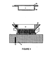
- FIG. 3 gives a more detailed view of an alternative embodiment for a solid sample [1] directly placed on top of the top plate [5] of the Peltier element [6].
- a (thin film) heater [3] and a (thin film) temperature sensor [4] are directly attached to the sample [1].
- the bottom plate [7] of the Peltier element [6] is placed on top of (part of) the bottom [8] of the first shield with the temperature sensor [12] also indicated.
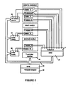
- FIG. 4 gives a more detailed view of an alternative embodiment for easy sample [1] and sample holder [2] replacement and no need for heater [3] or sensor [4] removal.
- an adapter piece [28] of a highly thermal conducting material e. g. aluminium, silver, copper
- This adapter piece contains an (embedded) temperature sensor [4] and a (thin film) heater [3].
- the sample [1] (solid or liquid) is contained in a (thin) small sample holder [2] consisting of a cup [29] and a lid [30] made of thin (soft) metal sheet.
- the cup [29] and the lid can be pressure closed.
- the sample holder cup [29] fits tightly in the cavity [31] of the adapter piece [28].
- Thermal contact between the sample holder cup [29] and the adapter piece [28] can be further improved by using (a minute quantity of) thermal conducting paste.
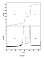
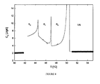
- Example 1 Enthalpy and heat capacity of first order transitions of an n-alkane.
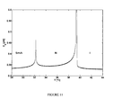
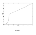
- Example 2 Enthalpy and heat capacity of first and second order phase transitions in a liquid crystal.
Landscapes
- Chemical & Material Sciences (AREA)
- Engineering & Computer Science (AREA)
- Combustion & Propulsion (AREA)
- Physics & Mathematics (AREA)
- General Physics & Mathematics (AREA)
- Chemical Kinetics & Catalysis (AREA)
- Health & Medical Sciences (AREA)
- Life Sciences & Earth Sciences (AREA)
- Analytical Chemistry (AREA)
- Biochemistry (AREA)
- General Health & Medical Sciences (AREA)
- Immunology (AREA)
- Pathology (AREA)
- Investigating Or Analyzing Materials Using Thermal Means (AREA)
Claims (15)
- Adiabatische Scanning-Kalorimeter-Vorrichtung, umfassend wenigstens ein Peltier-Element (6) und eine Probe (1) auf einem Probenhalter (2), wenigstens eine Heizvorrichtung (3), wenigstens einen thermischen oder adiabatischen Schild (8) (9), der die Probe (1) oder den Probenhalter (2) umgibt, dadurch gekennzeichnet, dass das adiabatische Scanning-Kalorimeter für gleichzeitige Messungen der Temperaturabhängigkeit der Wärmekapazität und Enthalpie von festen oder flüssigen Proben (1) und deren Phasenübergängen ist, wobei das wenigstens eine Peltier-Element (6), das als Differenzthermometer verwendet wird, zwischen der Probe oder dem Probenhalter und dem Schild angeordnet ist und gute mechanische und thermische Kontakte mit der Probe oder dem Probenhalter und dem Schild herstellt, so dass eine konstante voreingestellte Temperaturdifferenz oder eine Nulldifferenz zwischen der Probe oder dem Probenhalter und dem Schild aufrechterhalten wird.
- Vorrichtung nach Anspruch 1, wobei wenigstens ein Probenhalter (2) wenigstens einen Temperatursensor (4) auf dem Probenhalter (2) umfasst.
- Vorrichtung nach einem der vorhergehenden Ansprüche, wobei der Temperatursensor ein Thermistor oder ein Platin-Widerstandsthermometer ist.
- Vorrichtung nach einem der vorhergehenden Ansprüche, wobei die Vorrichtung mit einem Regler mit Servosystemen ausgestattet ist, um eine nahezu perfekte Gleichheit der Temperaturen von Probe und Schild im Heizmodus basierend auf den Ablesungen des Peltier-Elements aufrechtzuerhalten.
- Vorrichtung nach einem der Ansprüche 1 bis 4, die angepasst ist, so dass eine konstante Heiz-oder Kühlleistung an die Probe und/oder den Probenhalter abgegeben wird.
- Vorrichtung nach einem der Ansprüche 1 bis 4, die angepasst ist, so dass die Wärmeübertragung durch das Peltier-Element zum Aufheizen oder Abkühlen der Probe verwendet wird.
- Verwendung der Vorrichtung nach einem der Ansprüche 1 bis 6, um in einem Scanvorgang in thermodynamischem Gleichgewicht die Wärmekapazität und Enthalpie des Phasenübergangs der Probe gleichzeitig zu messen.
- Verwendung der Vorrichtung nach einem der Ansprüche 1 bis 6, um zwischen vorübergänglichen Übergangsenthalpieänderungen und echten latenten Wärmen bei Phasenübergängen erster Ordnung oder schwacher erster Ordnung zu trennen.
- Verwendung der Vorrichtung nach einem der Ansprüche 1 bis 6, um präzise Absolutwerte der spezifischen Wärme einer Probe durch Anwenden langsamer Scanraten, insbesondere niedriger als 0,2 Ks-1, zu gewinnen.
- Verwendung der Vorrichtung nach einem der Ansprüche 1 bis 6, um zwischen kontinuierlichen Phasenübergängen zweiter Ordnung und einem Phasenübergang schwacher erster Ordnung einer Probe zu unterscheiden.
- Verwendung der Vorrichtung nach einem der Ansprüche 1 bis 6, um in einem Scanvorgang einen Phasenübergang eines Stoffes als Einfluss eines Produktionsprozesses zu definieren oder zu kennzeichnen.
- Verwendung der Vorrichtung nach einem der Ansprüche 1 bis 6, um in einem Scanvorgang einen Phasenübergang in Flüssigkristallen, biologischen Systemen oder Zellmembranen zu definieren oder zu kennzeichnen.
- Verwendung der Vorrichtung nach einem der Ansprüche 1 bis 6, um in einem Scanvorgang einen geeigneten Stoff für eine definierte Eigenschaft zu definieren.
- Verwendung der Vorrichtung nach einem der Ansprüche 1 bis 6, um in einem Scanvorgang einen geeigneten Stoff für eine Verwendung auszuwählen.
- Verwendung der Vorrichtung nach einem der Ansprüche 1 bis 6, um den Energiegehalt einer Probe kondensierter Materie zu überwachen, indem man in einem Scanvorgang in thermodynamischem Gleichgewicht gleichzeitig die Temperaturabhängigkeit der Wärmekapazität und Enthalpie einer Probe und deren Phasenübergänge quantifiziert, wobei das Verfahren 1) das Abgeben einer konstanten Wärme- oder Kühlleistung an die Probe und das Halten der Temperaturdifferenzen mittels Peltier-Element zwischen einer untersuchten Probe und ihrem umgebenden thermischen Schild auf null oder einem voreingestellten festen Wert während dem Temperatur-Scanning über breite Bereiche ohne Näherungen umfasst.
Applications Claiming Priority (3)
| Application Number | Priority Date | Filing Date | Title |
|---|---|---|---|
| GBGB1011522.8A GB201011522D0 (en) | 2010-07-08 | 2010-07-08 | Adiabatic scanning calorimeter |
| GBGB1014995.3A GB201014995D0 (en) | 2010-09-09 | 2010-09-09 | Adiabatic scanning calorimeter |
| PCT/BE2011/000042 WO2012003553A1 (en) | 2010-07-08 | 2011-07-07 | Adiabatic scanning calorimeter |
Publications (2)
| Publication Number | Publication Date |
|---|---|
| EP2591328A1 EP2591328A1 (de) | 2013-05-15 |
| EP2591328B1 true EP2591328B1 (de) | 2015-09-02 |
Family
ID=45440716
Family Applications (1)
| Application Number | Title | Priority Date | Filing Date |
|---|---|---|---|
| EP11749073.0A Active EP2591328B1 (de) | 2010-07-08 | 2011-07-07 | Adiabatisches erfassungskalorimeter |
Country Status (3)
| Country | Link |
|---|---|
| US (1) | US9310263B2 (de) |
| EP (1) | EP2591328B1 (de) |
| WO (1) | WO2012003553A1 (de) |
Families Citing this family (21)
| Publication number | Priority date | Publication date | Assignee | Title |
|---|---|---|---|---|
| US9869595B2 (en) | 2012-07-06 | 2018-01-16 | Council Of Scientific & Industrial Research | Device for thermokinetic property measurement |
| US9593988B1 (en) | 2013-07-23 | 2017-03-14 | Calmetrix, Inc. | Systems and methods of thermal energy measurement |
| CN103743775B (zh) * | 2013-10-22 | 2016-04-20 | 南京大学 | 一种可与其它显微结构表征技术联用的冷热台型高速量热仪 |
| FR3012880B1 (fr) * | 2013-11-07 | 2023-01-13 | Centre Nat Rech Scient | Calorimetre a temperature stabilisee. |
| US10617891B2 (en) | 2015-04-23 | 2020-04-14 | Sun Nuclear Corporation | Radiation detector calibration |
| EP3583393B1 (de) * | 2017-02-20 | 2021-04-07 | Soojus AB | Kalorimetrische sonde und verfahren zur kalorimetrischen messung |
| EP3589366B1 (de) | 2017-02-28 | 2025-12-10 | Sun Nuclear Corporation | Verifizierung einer strahlentherapiebehandlung mit transitbildern einer elektronischen portalbildgebungsvorrichtung |
| FR3071606B1 (fr) * | 2017-09-27 | 2019-09-20 | Institut National De Recherche Pour L'agriculture, L'alimentation Et L'environnement | Systeme et procede de calorimetrie a determination multiple de flux de chaleur |
| US11499928B2 (en) * | 2018-08-24 | 2022-11-15 | University Of Wyoming | Methods and systems for isochoric measurements using differential scanning calorimetry |
| US11278744B2 (en) | 2018-09-28 | 2022-03-22 | Sun Nuclear Corporation | Systems and methods to account for tilt of a radiation measurement system |
| CN110044955B (zh) * | 2019-02-15 | 2024-04-02 | 上海海事大学 | 用于稳态法测量膏状材料导热性能的样品支架及测量方法 |
| US11600004B2 (en) | 2019-07-10 | 2023-03-07 | Sun Nuclear Corporation | Image-based radiation therapy quality assurance |
| US12011616B2 (en) | 2019-07-10 | 2024-06-18 | Sun Nuclear Corporation | Image-based radiation therapy quality assurance |
| WO2021007459A1 (en) | 2019-07-10 | 2021-01-14 | Sun Nuclear Corporation | Scintillator-based radiation therapy quality assurance |
| RU2727342C1 (ru) * | 2019-10-16 | 2020-07-21 | Федеральное государственное унитарное предприятие "Всероссийский научно-исследовательский институт метрологии им. Д.И. Менделеева" | Адиабатический калориметр |
| US11047748B1 (en) * | 2020-08-14 | 2021-06-29 | Frank L. Wu | Adiabatic power compensation differential scanning calorimeter |
| AT524363B1 (de) | 2020-10-30 | 2022-06-15 | Anton Paar Gmbh | Messgerät mit elektrothermischem Wandler zum Einstellen eines thermischen Widerstandes, und Betriebsverfahren |
| CN114594131B (zh) * | 2020-12-07 | 2024-11-05 | 中国科学院大连化学物理研究所 | 一种量热仪中的绝热屏固定装置 |
| CN114636730B (zh) * | 2020-12-15 | 2024-11-08 | 中国科学院大连化学物理研究所 | 一种量热装置绝热屏 |
| US12201850B2 (en) | 2022-06-16 | 2025-01-21 | Sun Nuclear Corporation | High dose rate radiation therapy systems and dosimetry |
| US12544596B2 (en) | 2023-03-30 | 2026-02-10 | Sun Nuclear Corporation | Adjustable radiation detector support |
Family Cites Families (5)
| Publication number | Priority date | Publication date | Assignee | Title |
|---|---|---|---|---|
| SE377348B (de) * | 1972-07-14 | 1975-06-30 | Mo Och Domsjoe Ab | |
| US4255961A (en) * | 1978-10-17 | 1981-03-17 | University Of Va. Alumni Patents Foundation | Differential calorimeter based on the heat leak principle |
| GB2280506A (en) * | 1993-07-29 | 1995-02-01 | Euratom | Thermostatic device |
| US5813763A (en) * | 1996-10-11 | 1998-09-29 | Microcal Incorporated | Ultrasensitive differential microcalorimeter |
| US8147133B2 (en) * | 2009-05-26 | 2012-04-03 | The United States Of America As Represented By The Secretary Of The Navy | Top loaded twin cell calorimeter system with removable reference |
-
2011
- 2011-07-07 EP EP11749073.0A patent/EP2591328B1/de active Active
- 2011-07-07 WO PCT/BE2011/000042 patent/WO2012003553A1/en not_active Ceased
- 2011-07-07 US US13/808,278 patent/US9310263B2/en active Active
Also Published As
| Publication number | Publication date |
|---|---|
| US20130121369A1 (en) | 2013-05-16 |
| WO2012003553A1 (en) | 2012-01-12 |
| US9310263B2 (en) | 2016-04-12 |
| EP2591328A1 (de) | 2013-05-15 |
Similar Documents
| Publication | Publication Date | Title |
|---|---|---|
| EP2591328B1 (de) | Adiabatisches erfassungskalorimeter | |
| WO2012103601A1 (en) | Differential adiabatic scanning calorimeter | |
| Kabo et al. | Details of calibration of a scanning calorimeter of the triple heat bridge type | |
| Staas et al. | Experiments on laminar and turbulent flow of He II in wide capillaries | |
| Leys et al. | Investigation of the melting behavior of the reference materials biphenyl and phenyl salicylate by a new type adiabatic scanning calorimeter | |
| Thoen et al. | Investigations of phase transitions in liquid crystals by means of adiabatic scanning calorimetry | |
| Leys et al. | Application of a novel type of adiabatic scanning calorimeter for high-resolution thermal data near the melting point of gallium | |
| Hansen et al. | The art of calorimetry | |
| Losada-Pérez et al. | Measurements of heat capacity and enthalpy of phase change materials by adiabatic scanning calorimetry | |
| Inaba | Nano-watt stabilized DSC and ITS applications | |
| Blumm et al. | Accurate measurement of transformation energetics and specific heat by DSC in the high-temperature region | |
| Pérez-Enciso et al. | Low-temperature calorimetry on molecular glasses and crystals | |
| Razouk et al. | A new in situ electrical calibration system for high temperature Calvet calorimeters | |
| Pocheau et al. | Cell tip undercooling in directional solidification | |
| Skoglund et al. | Accurate temperature calibration of differential scanning calorimeters | |
| Schnelle et al. | Critical review of small sample calorimetry: improvement by auto-adaptive thermal shield control | |
| Thoen | High resolution adiabatic scanning calorimetry and heat capacities | |
| Martins et al. | The temperature calibration on cooling of differential scanning calorimeters | |
| Thoen et al. | Enthalpy measurements of condensed matter by Peltier-element-based adiabatic scanning calorimetry (pASC) | |
| Manohar et al. | Phase transition studies of some cholesteric liquid crystals and their mixtures using dielectric, optical transmittance and density measurement techniques | |
| JPS61159141A (ja) | 多孔体組織用熱測定装置 | |
| Vargas et al. | A versatile and high-precision solution—reaction isoperibol calorimeter | |
| Brando | Development of a relaxation calorimeter for temperatures between 0.05 and 4 K | |
| Tanasijczuk et al. | High resolution calorimeter for the investigation of melting in organic and biological materials | |
| Sebedash et al. | Osmotic pressure of 3He-4He solutions at 25.3 bar and low temperatures |
Legal Events
| Date | Code | Title | Description |
|---|---|---|---|
| PUAI | Public reference made under article 153(3) epc to a published international application that has entered the european phase |
Free format text: ORIGINAL CODE: 0009012 |
|
| 17P | Request for examination filed |
Effective date: 20121220 |
|
| AK | Designated contracting states |
Kind code of ref document: A1 Designated state(s): AL AT BE BG CH CY CZ DE DK EE ES FI FR GB GR HR HU IE IS IT LI LT LU LV MC MK MT NL NO PL PT RO RS SE SI SK SM TR |
|
| DAX | Request for extension of the european patent (deleted) | ||
| GRAP | Despatch of communication of intention to grant a patent |
Free format text: ORIGINAL CODE: EPIDOSNIGR1 |
|
| INTG | Intention to grant announced |
Effective date: 20150318 |
|
| GRAS | Grant fee paid |
Free format text: ORIGINAL CODE: EPIDOSNIGR3 |
|
| RAP1 | Party data changed (applicant data changed or rights of an application transferred) |
Owner name: KATHOLIEKE UNIVERSITEIT LEUVEN |
|
| GRAA | (expected) grant |
Free format text: ORIGINAL CODE: 0009210 |
|
| AK | Designated contracting states |
Kind code of ref document: B1 Designated state(s): AL AT BE BG CH CY CZ DE DK EE ES FI FR GB GR HR HU IE IS IT LI LT LU LV MC MK MT NL NO PL PT RO RS SE SI SK SM TR |
|
| REG | Reference to a national code |
Ref country code: GB Ref legal event code: FG4D |
|
| REG | Reference to a national code |
Ref country code: AT Ref legal event code: REF Ref document number: 746916 Country of ref document: AT Kind code of ref document: T Effective date: 20150915 Ref country code: CH Ref legal event code: EP |
|
| REG | Reference to a national code |
Ref country code: IE Ref legal event code: FG4D |
|
| REG | Reference to a national code |
Ref country code: DE Ref legal event code: R096 Ref document number: 602011019396 Country of ref document: DE |
|
| REG | Reference to a national code |
Ref country code: AT Ref legal event code: MK05 Ref document number: 746916 Country of ref document: AT Kind code of ref document: T Effective date: 20150902 |
|
| PG25 | Lapsed in a contracting state [announced via postgrant information from national office to epo] |
Ref country code: GR Free format text: LAPSE BECAUSE OF FAILURE TO SUBMIT A TRANSLATION OF THE DESCRIPTION OR TO PAY THE FEE WITHIN THE PRESCRIBED TIME-LIMIT Effective date: 20151203 Ref country code: NO Free format text: LAPSE BECAUSE OF FAILURE TO SUBMIT A TRANSLATION OF THE DESCRIPTION OR TO PAY THE FEE WITHIN THE PRESCRIBED TIME-LIMIT Effective date: 20151202 Ref country code: LV Free format text: LAPSE BECAUSE OF FAILURE TO SUBMIT A TRANSLATION OF THE DESCRIPTION OR TO PAY THE FEE WITHIN THE PRESCRIBED TIME-LIMIT Effective date: 20150902 Ref country code: FI Free format text: LAPSE BECAUSE OF FAILURE TO SUBMIT A TRANSLATION OF THE DESCRIPTION OR TO PAY THE FEE WITHIN THE PRESCRIBED TIME-LIMIT Effective date: 20150902 Ref country code: LT Free format text: LAPSE BECAUSE OF FAILURE TO SUBMIT A TRANSLATION OF THE DESCRIPTION OR TO PAY THE FEE WITHIN THE PRESCRIBED TIME-LIMIT Effective date: 20150902 |
|
| REG | Reference to a national code |
Ref country code: LT Ref legal event code: MG4D Ref country code: NL Ref legal event code: MP Effective date: 20150902 |
|
| PG25 | Lapsed in a contracting state [announced via postgrant information from national office to epo] |
Ref country code: SE Free format text: LAPSE BECAUSE OF FAILURE TO SUBMIT A TRANSLATION OF THE DESCRIPTION OR TO PAY THE FEE WITHIN THE PRESCRIBED TIME-LIMIT Effective date: 20150902 Ref country code: ES Free format text: LAPSE BECAUSE OF FAILURE TO SUBMIT A TRANSLATION OF THE DESCRIPTION OR TO PAY THE FEE WITHIN THE PRESCRIBED TIME-LIMIT Effective date: 20150902 Ref country code: RS Free format text: LAPSE BECAUSE OF FAILURE TO SUBMIT A TRANSLATION OF THE DESCRIPTION OR TO PAY THE FEE WITHIN THE PRESCRIBED TIME-LIMIT Effective date: 20150902 Ref country code: AT Free format text: LAPSE BECAUSE OF FAILURE TO SUBMIT A TRANSLATION OF THE DESCRIPTION OR TO PAY THE FEE WITHIN THE PRESCRIBED TIME-LIMIT Effective date: 20150902 Ref country code: PL Free format text: LAPSE BECAUSE OF FAILURE TO SUBMIT A TRANSLATION OF THE DESCRIPTION OR TO PAY THE FEE WITHIN THE PRESCRIBED TIME-LIMIT Effective date: 20150902 |
|
| PG25 | Lapsed in a contracting state [announced via postgrant information from national office to epo] |
Ref country code: CZ Free format text: LAPSE BECAUSE OF FAILURE TO SUBMIT A TRANSLATION OF THE DESCRIPTION OR TO PAY THE FEE WITHIN THE PRESCRIBED TIME-LIMIT Effective date: 20150902 Ref country code: NL Free format text: LAPSE BECAUSE OF FAILURE TO SUBMIT A TRANSLATION OF THE DESCRIPTION OR TO PAY THE FEE WITHIN THE PRESCRIBED TIME-LIMIT Effective date: 20150902 Ref country code: SK Free format text: LAPSE BECAUSE OF FAILURE TO SUBMIT A TRANSLATION OF THE DESCRIPTION OR TO PAY THE FEE WITHIN THE PRESCRIBED TIME-LIMIT Effective date: 20150902 Ref country code: IS Free format text: LAPSE BECAUSE OF FAILURE TO SUBMIT A TRANSLATION OF THE DESCRIPTION OR TO PAY THE FEE WITHIN THE PRESCRIBED TIME-LIMIT Effective date: 20160102 Ref country code: IT Free format text: LAPSE BECAUSE OF FAILURE TO SUBMIT A TRANSLATION OF THE DESCRIPTION OR TO PAY THE FEE WITHIN THE PRESCRIBED TIME-LIMIT Effective date: 20150902 Ref country code: EE Free format text: LAPSE BECAUSE OF FAILURE TO SUBMIT A TRANSLATION OF THE DESCRIPTION OR TO PAY THE FEE WITHIN THE PRESCRIBED TIME-LIMIT Effective date: 20150902 |
|
| PG25 | Lapsed in a contracting state [announced via postgrant information from national office to epo] |
Ref country code: PT Free format text: LAPSE BECAUSE OF FAILURE TO SUBMIT A TRANSLATION OF THE DESCRIPTION OR TO PAY THE FEE WITHIN THE PRESCRIBED TIME-LIMIT Effective date: 20160104 Ref country code: RO Free format text: LAPSE BECAUSE OF FAILURE TO SUBMIT A TRANSLATION OF THE DESCRIPTION OR TO PAY THE FEE WITHIN THE PRESCRIBED TIME-LIMIT Effective date: 20150902 |
|
| REG | Reference to a national code |
Ref country code: DE Ref legal event code: R097 Ref document number: 602011019396 Country of ref document: DE |
|
| PLBE | No opposition filed within time limit |
Free format text: ORIGINAL CODE: 0009261 |
|
| STAA | Information on the status of an ep patent application or granted ep patent |
Free format text: STATUS: NO OPPOSITION FILED WITHIN TIME LIMIT |
|
| REG | Reference to a national code |
Ref country code: FR Ref legal event code: PLFP Year of fee payment: 6 |
|
| 26N | No opposition filed |
Effective date: 20160603 |
|
| PG25 | Lapsed in a contracting state [announced via postgrant information from national office to epo] |
Ref country code: DK Free format text: LAPSE BECAUSE OF FAILURE TO SUBMIT A TRANSLATION OF THE DESCRIPTION OR TO PAY THE FEE WITHIN THE PRESCRIBED TIME-LIMIT Effective date: 20150902 Ref country code: SI Free format text: LAPSE BECAUSE OF FAILURE TO SUBMIT A TRANSLATION OF THE DESCRIPTION OR TO PAY THE FEE WITHIN THE PRESCRIBED TIME-LIMIT Effective date: 20150902 |
|
| PG25 | Lapsed in a contracting state [announced via postgrant information from national office to epo] |
Ref country code: BE Free format text: LAPSE BECAUSE OF FAILURE TO SUBMIT A TRANSLATION OF THE DESCRIPTION OR TO PAY THE FEE WITHIN THE PRESCRIBED TIME-LIMIT Effective date: 20150902 |
|
| PG25 | Lapsed in a contracting state [announced via postgrant information from national office to epo] |
Ref country code: MC Free format text: LAPSE BECAUSE OF FAILURE TO SUBMIT A TRANSLATION OF THE DESCRIPTION OR TO PAY THE FEE WITHIN THE PRESCRIBED TIME-LIMIT Effective date: 20150902 |
|
| REG | Reference to a national code |
Ref country code: IE Ref legal event code: MM4A |
|
| REG | Reference to a national code |
Ref country code: FR Ref legal event code: PLFP Year of fee payment: 7 |
|
| PG25 | Lapsed in a contracting state [announced via postgrant information from national office to epo] |
Ref country code: IE Free format text: LAPSE BECAUSE OF NON-PAYMENT OF DUE FEES Effective date: 20160707 |
|
| PG25 | Lapsed in a contracting state [announced via postgrant information from national office to epo] |
Ref country code: LU Free format text: LAPSE BECAUSE OF NON-PAYMENT OF DUE FEES Effective date: 20160707 |
|
| PG25 | Lapsed in a contracting state [announced via postgrant information from national office to epo] |
Ref country code: HU Free format text: LAPSE BECAUSE OF FAILURE TO SUBMIT A TRANSLATION OF THE DESCRIPTION OR TO PAY THE FEE WITHIN THE PRESCRIBED TIME-LIMIT; INVALID AB INITIO Effective date: 20110707 Ref country code: SM Free format text: LAPSE BECAUSE OF FAILURE TO SUBMIT A TRANSLATION OF THE DESCRIPTION OR TO PAY THE FEE WITHIN THE PRESCRIBED TIME-LIMIT Effective date: 20150902 Ref country code: CY Free format text: LAPSE BECAUSE OF FAILURE TO SUBMIT A TRANSLATION OF THE DESCRIPTION OR TO PAY THE FEE WITHIN THE PRESCRIBED TIME-LIMIT Effective date: 20150902 |
|
| PG25 | Lapsed in a contracting state [announced via postgrant information from national office to epo] |
Ref country code: MK Free format text: LAPSE BECAUSE OF FAILURE TO SUBMIT A TRANSLATION OF THE DESCRIPTION OR TO PAY THE FEE WITHIN THE PRESCRIBED TIME-LIMIT Effective date: 20150902 Ref country code: HR Free format text: LAPSE BECAUSE OF FAILURE TO SUBMIT A TRANSLATION OF THE DESCRIPTION OR TO PAY THE FEE WITHIN THE PRESCRIBED TIME-LIMIT Effective date: 20150902 Ref country code: MT Free format text: LAPSE BECAUSE OF NON-PAYMENT OF DUE FEES Effective date: 20160731 Ref country code: TR Free format text: LAPSE BECAUSE OF FAILURE TO SUBMIT A TRANSLATION OF THE DESCRIPTION OR TO PAY THE FEE WITHIN THE PRESCRIBED TIME-LIMIT Effective date: 20150902 |
|
| REG | Reference to a national code |
Ref country code: FR Ref legal event code: PLFP Year of fee payment: 8 |
|
| PG25 | Lapsed in a contracting state [announced via postgrant information from national office to epo] |
Ref country code: BG Free format text: LAPSE BECAUSE OF FAILURE TO SUBMIT A TRANSLATION OF THE DESCRIPTION OR TO PAY THE FEE WITHIN THE PRESCRIBED TIME-LIMIT Effective date: 20150902 |
|
| PG25 | Lapsed in a contracting state [announced via postgrant information from national office to epo] |
Ref country code: AL Free format text: LAPSE BECAUSE OF FAILURE TO SUBMIT A TRANSLATION OF THE DESCRIPTION OR TO PAY THE FEE WITHIN THE PRESCRIBED TIME-LIMIT Effective date: 20150902 |
|
| P01 | Opt-out of the competence of the unified patent court (upc) registered |
Effective date: 20230526 |
|
| PGFP | Annual fee paid to national office [announced via postgrant information from national office to epo] |
Ref country code: DE Payment date: 20240719 Year of fee payment: 14 |
|
| PGFP | Annual fee paid to national office [announced via postgrant information from national office to epo] |
Ref country code: GB Payment date: 20240722 Year of fee payment: 14 |
|
| PGFP | Annual fee paid to national office [announced via postgrant information from national office to epo] |
Ref country code: FR Payment date: 20240730 Year of fee payment: 14 |
|
| PGFP | Annual fee paid to national office [announced via postgrant information from national office to epo] |
Ref country code: CH Payment date: 20240801 Year of fee payment: 14 |