EP2590776B1 - Method of joining two bars end-on by means of electron beam welding - Google Patents
Method of joining two bars end-on by means of electron beam welding Download PDFInfo
- Publication number
- EP2590776B1 EP2590776B1 EP11760738.2A EP11760738A EP2590776B1 EP 2590776 B1 EP2590776 B1 EP 2590776B1 EP 11760738 A EP11760738 A EP 11760738A EP 2590776 B1 EP2590776 B1 EP 2590776B1
- Authority
- EP
- European Patent Office
- Prior art keywords
- electron beam
- sleeve
- along
- welding
- eba
- Prior art date
- Legal status (The legal status is an assumption and is not a legal conclusion. Google has not performed a legal analysis and makes no representation as to the accuracy of the status listed.)
- Not-in-force
Links
Images

Classifications
-
- B—PERFORMING OPERATIONS; TRANSPORTING
- B23—MACHINE TOOLS; METAL-WORKING NOT OTHERWISE PROVIDED FOR
- B23K—SOLDERING OR UNSOLDERING; WELDING; CLADDING OR PLATING BY SOLDERING OR WELDING; CUTTING BY APPLYING HEAT LOCALLY, e.g. FLAME CUTTING; WORKING BY LASER BEAM
- B23K15/00—Electron-beam welding or cutting
- B23K15/0046—Welding
- B23K15/0053—Seam welding
- B23K15/006—Seam welding of rectilinear seams
-
- B—PERFORMING OPERATIONS; TRANSPORTING
- B23—MACHINE TOOLS; METAL-WORKING NOT OTHERWISE PROVIDED FOR
- B23K—SOLDERING OR UNSOLDERING; WELDING; CLADDING OR PLATING BY SOLDERING OR WELDING; CUTTING BY APPLYING HEAT LOCALLY, e.g. FLAME CUTTING; WORKING BY LASER BEAM
- B23K37/00—Auxiliary devices or processes, not specially adapted to a procedure covered by only one of the preceding main groups
- B23K37/04—Auxiliary devices or processes, not specially adapted to a procedure covered by only one of the preceding main groups for holding or positioning work
- B23K37/053—Auxiliary devices or processes, not specially adapted to a procedure covered by only one of the preceding main groups for holding or positioning work aligning cylindrical work; Clamping devices therefor
- B23K37/0533—Auxiliary devices or processes, not specially adapted to a procedure covered by only one of the preceding main groups for holding or positioning work aligning cylindrical work; Clamping devices therefor external pipe alignment clamps
-
- F—MECHANICAL ENGINEERING; LIGHTING; HEATING; WEAPONS; BLASTING
- F01—MACHINES OR ENGINES IN GENERAL; ENGINE PLANTS IN GENERAL; STEAM ENGINES
- F01D—NON-POSITIVE DISPLACEMENT MACHINES OR ENGINES, e.g. STEAM TURBINES
- F01D5/00—Blades; Blade-carrying members; Heating, heat-insulating, cooling or antivibration means on the blades or the members
- F01D5/02—Blade-carrying members, e.g. rotors
- F01D5/06—Rotors for more than one axial stage, e.g. of drum or multiple disc type; Details thereof, e.g. shafts, shaft connections
- F01D5/063—Welded rotors
-
- B—PERFORMING OPERATIONS; TRANSPORTING
- B23—MACHINE TOOLS; METAL-WORKING NOT OTHERWISE PROVIDED FOR
- B23K—SOLDERING OR UNSOLDERING; WELDING; CLADDING OR PLATING BY SOLDERING OR WELDING; CUTTING BY APPLYING HEAT LOCALLY, e.g. FLAME CUTTING; WORKING BY LASER BEAM
- B23K2101/00—Articles made by soldering, welding or cutting
- B23K2101/001—Turbines
-
- B—PERFORMING OPERATIONS; TRANSPORTING
- B23—MACHINE TOOLS; METAL-WORKING NOT OTHERWISE PROVIDED FOR
- B23K—SOLDERING OR UNSOLDERING; WELDING; CLADDING OR PLATING BY SOLDERING OR WELDING; CUTTING BY APPLYING HEAT LOCALLY, e.g. FLAME CUTTING; WORKING BY LASER BEAM
- B23K2101/00—Articles made by soldering, welding or cutting
- B23K2101/04—Tubular or hollow articles
- B23K2101/06—Tubes
-
- B—PERFORMING OPERATIONS; TRANSPORTING
- B23—MACHINE TOOLS; METAL-WORKING NOT OTHERWISE PROVIDED FOR
- B23K—SOLDERING OR UNSOLDERING; WELDING; CLADDING OR PLATING BY SOLDERING OR WELDING; CUTTING BY APPLYING HEAT LOCALLY, e.g. FLAME CUTTING; WORKING BY LASER BEAM
- B23K37/00—Auxiliary devices or processes, not specially adapted to a procedure covered by only one of the preceding main groups
- B23K37/04—Auxiliary devices or processes, not specially adapted to a procedure covered by only one of the preceding main groups for holding or positioning work
- B23K37/053—Auxiliary devices or processes, not specially adapted to a procedure covered by only one of the preceding main groups for holding or positioning work aligning cylindrical work; Clamping devices therefor
-
- F—MECHANICAL ENGINEERING; LIGHTING; HEATING; WEAPONS; BLASTING
- F05—INDEXING SCHEMES RELATING TO ENGINES OR PUMPS IN VARIOUS SUBCLASSES OF CLASSES F01-F04
- F05D—INDEXING SCHEME FOR ASPECTS RELATING TO NON-POSITIVE-DISPLACEMENT MACHINES OR ENGINES, GAS-TURBINES OR JET-PROPULSION PLANTS
- F05D2230/00—Manufacture
- F05D2230/20—Manufacture essentially without removing material
- F05D2230/23—Manufacture essentially without removing material by permanently joining parts together
- F05D2230/232—Manufacture essentially without removing material by permanently joining parts together by welding
- F05D2230/233—Electron beam welding
-
- F—MECHANICAL ENGINEERING; LIGHTING; HEATING; WEAPONS; BLASTING
- F05—INDEXING SCHEMES RELATING TO ENGINES OR PUMPS IN VARIOUS SUBCLASSES OF CLASSES F01-F04
- F05D—INDEXING SCHEME FOR ASPECTS RELATING TO NON-POSITIVE-DISPLACEMENT MACHINES OR ENGINES, GAS-TURBINES OR JET-PROPULSION PLANTS
- F05D2240/00—Components
- F05D2240/60—Shafts
Definitions
- the invention relates to a method for the frontal connection of a first rod to a second rod by means of electron beam welding according to the preamble of claim 1 (see, for example, US Pat. US 4,063,062 ).
- shaft pieces are often butt-end blunt welded together by means of a Elektronenstrahlsch spaapparates without further filler material, the two juxtaposed rod pieces in the region of the abutting ends by means of an entering into the joint electron beam to a melt be brought, which results after cooling in a connection.
- the main difficulty of an electron beam welded radial seam in a shaft or other rod material is the production of the defect-free seam beginning and the seam end. Under the beginning of the seam is to be understood the Einfädel Scheme of the electron beam and below the seam end of the Ausfädel Kunststoff the electron beam from the material.
- the invention has the object to improve the quality of the weld described above without complicating the control of the electron beam additionally complicated.
- the US 4,063,062 describes a conventional electronic beam welding of round shaft sections end to end, wherein a Einfädel Suite and a Ausfädel Suite disturb the homogeneity of the weld.
- the wrapping according to the invention of a joining zone of the two adjoining ends of the connecting rods to be connected by means of a sleeve with the threading and the Ausfädel Stud the electron beam outside of the material actually to be joined makes it possible to produce a completely homogeneous material structure in the joining zone of the actually connected parts.
- the method according to the invention also differs from the state of the art in that actually, as originally intended, only two components are connected to one another, but rather three components are connected to one another by the electron beam welding.
- the sleeve has an inner contour which is adapted to the outer contour of the rods in the region of the weld.
- the manufacture of a fit on the sleeve relative to the two rod ends is useful in the accuracy range of +/- 0,1mm related to the diameter.
- the sleeve has a parting line, which is arranged such that the sleeve can be placed around the profiles of the rods.
- the sleeve may have a rectangular outer cross section.
- the rectangular outer cross-section also has the advantage that in a direction of advance of the electron beam apparatus parallel to the surface of the sleeve, the penetration depth of the electron beam is assumed to be constant, resulting in a homogeneous material structure at the weld.
- the sleeve in the region of the joining zone expediently consists of the same material as the two rods to be joined, at least in the region of the weld, so that a possible material transition between the three parts involved results in a homogeneous material structure in the region of the joining zone or weld.
- a possible lack of material in the joining zone for example, by a minimally remaining axial gap in the region of the two rod ends, which are to be joined together - be compensated by the then available as a filler material of the sleeve.
- a removal of the sleeve is preferably carried out by cutting, in the case of the wave simply by over-turning the weld.
- the electron beam can guide the shaft cross section or rod cross section through a simple electron beam control from left to right or vice versa along the welding point.
- the electron beam end always remains in the sleeve material, if the sleeve material is formed sufficiently thick enough in the direction of the penetration depth of the electron beam.
- the threading area and the Ausfädel Scheme can be selected according to the invention very short be because the occurring welding defects are mechanically processed after welding. Accordingly, regardless of welding errors, the control of the electron beam in the sleeve material can be done.
- the joint welding can be carried out by welding from two sides. These two sides are preferably directly opposite one another, so that there is at least a minimal overlap between the penetration tip of the electron beam or the welding depth at the welding from the first side along a first direction of progress and the penetration depth or the welding depth during the welding along a second Direction of progress.
- the electron beam penetrates into the workpiece, but also arranged from obliquely Side of the sleeve or in a rectangular cross-section of the electron beam simultaneously or successively penetrates from the surfaces of all four sides of the sleeve into the workpieces.
- the shaft cross sections or rod cross sections of the workpieces to be joined can be round, oval, triangular, square, rectangular, hexagonal or otherwise polygonal. Likewise, undercuts or concave contours are possible. In principle, any bar profile can be connected by means of the method according to the invention.
- FIG. 4 shows a longitudinal section through a sleeve according to the invention SL, which is arranged around a joint of two frontally abutting abutting rods, a first rod B1 and a second rod B2.
- SL a sleeve according to the invention
- the very narrow gap SG reduces in areas of the face contact between the bars B1, B2 to a width of up to 0.
- the two bars B1, B2 extend along a common longitudinal axis X and are aligned coaxially with one another.
- an electron beam welding apparatus EBA Radially to the longitudinal axis X, an electron beam welding apparatus EBA is arranged, which emits an electron beam EB radially on the region of the narrow gap SG and in this way connects the two rods B1, B2 at this weld WP with the melt.
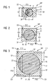
- FIGS. 1 to 3 each represent different diameters D of the rods B1, B2 and associated different embodiments of the welding method according to the invention.
- the diameter D of the bars B1, B2 is in the illustration of FIG. 1 smaller than the maximum welding depth WD of the electron beam EB along a first advancing direction PD1 of the electron beam welding apparatus EBA.
- Decisive for the selection of the welding method according to the invention is the maximum thickness T of a thickness curve DT illustrated in, for example FIG. 1 of the cross section of the bar B1, B2 along a first advancing direction PD1 and further advancing directions PD1, PD2, PD3, PD4 in the region of the weld WP in the FIGS. 2 and 3 ,
- the maximum thickness T is equal to the diameter D of the bars B1, B2.
- the two rods B1, B2 are aligned with one another along a longitudinal axis X.
- the two-part cuff SL is placed around the joint or weld WP of the rods B1, B2, so that the cuff SL surrounds the weld WP in the circumferential direction with respect to the longitudinal axis X.
- this takes place in the FIGS. 1 to 3 illustrated electron beam welding by means along an advancing direction PD1 - PD4 moving electron beam welding apparatus EBA along the surface SF of the cuff SL.
- the cuff has a rectangular outer cross section and has a parting line TF, which is arranged such that the cuff SL can be placed around the bars B1, B2.
- the welding depth WD of the electron beam EB is larger than the diameter D and the maximum thickness T of the bar B1, B2 along the thickness direction DT along the first advancing direction PD1. Accordingly, a single pass through the assembly of the two rods B1, B2 and the cuff SL is sufficient to completely connect the rods together by the weld.
- the material of the cuff SL which is identical to the material of the two rods B1, B2, can serve as an additional material for filling in defects in the region of the weld seam.
- the FIG. 2 shows a case that the maximum penetration depth WD of the electron beam EB is smaller than the maximum thickness T of the bars B1, B2 along the first advancing direction PD1 but greater than half of this maximum thickness T and the diameter D, respectively, because it is a circular Cross section acts. Accordingly, the workpiece is in the in FIG. 2 shown welded in two steps with the electron beam EB.
- the electron beam welding apparatus EBA (or the component moves under an electron beam EB) moves along a first advancing direction PD1 along the weld WP and the surface SF of the sleeve SL
- the electron beam welding apparatus EBA moves (or the component moves under an electron beam EB) in antiparallel second advancing direction PD2 on the opposite side of the rectangular shaped sleeve SL also parallel to the surface SF, so that an overlap occurs between the first welding passage and the second welding passage.
- the maximum thickness T and the diameter D of the round bars B1, B2 is more than twice as large as the maximum welding depth WD of the electron beam EB and accordingly there is a welding in four steps, the steps each by their different progress direction PD1 - Distinguish PD4 of the electron beam welding apparatus EBA and the different orientation of the electron beam EB in the plane of the weld WP.
- these are four progress directions oriented perpendicular to one another, which are each aligned parallel to the respective planar surface section of the sleeve SL.
Description
Die Erfindung betrifft ein Verfahren zur stirnseitigen Verbindung einer ersten Stange mit einer zweiten Stange mittels Elektronenstrahlschweißens gemäß dem Oberbegriff des Anspruchs 1 (siehe, z.B.,
Insbesondere bei der Fertigung von Wellen für Turbomaschinen, beispielsweise Turboverdichtern, Dampfturbinen oder Gasturbinen werden häufig Wellenstücke stirnseitig stumpf aneinander geschweißt, indem mittels eines Elektronenstrahlschweißapparates ohne weiteren Zusatzwerkstoff die beiden aneinander gelegten Stangenstücke im Bereich der aneinanderstoßenden Enden mittels eines in die Fuge eintretenden Elektronenstrahls zu einer Schmelze gebracht werden, die nach dem Erkalten in einer Verbindung resultiert. Die Hauptschwierigkeit einer elektronenstrahlgeschweißten Radialnaht bei einer Welle oder einem sonstigen Stangenmaterial besteht in der Fertigung des fehlerfreien Nahtanfangs und des Nahtendes. Unter dem Nahtanfang ist der Einfädelbereich des Elektronenstrahls zu verstehen und unter dem Nahtende der Ausfädelbereich des Elektronenstrahls aus dem Werkstoff. Weitere Störungen der Homogenität des Werkstoffgefüges ergeben sich durch etwaige Überschweißungen der bereits geschweißten Schweißnaht bei Überlappungen von Wirkungsbereichen des Elektronenstrahls in dem Werkstoff während unterschiedlicher Schweißvorgänge. Zusätzliche Schwierigkeiten ergeben sich bei kleinen Wellendurchmessers bzw. kleinen Stangendicken durch den Wärmestau im Bereich der Bauteilmitte, wodurch eine fehlerfreie Schweißung im Überlappbereich und im Ausfädelbereich der Schweißverbindung nicht möglich ist.In particular, in the production of shafts for turbomachinery, such as turbocompressors, steam turbines or gas turbines shaft pieces are often butt-end blunt welded together by means of a Elektronenstrahlschweißapparates without further filler material, the two juxtaposed rod pieces in the region of the abutting ends by means of an entering into the joint electron beam to a melt be brought, which results after cooling in a connection. The main difficulty of an electron beam welded radial seam in a shaft or other rod material is the production of the defect-free seam beginning and the seam end. Under the beginning of the seam is to be understood the Einfädelbereich of the electron beam and below the seam end of the Ausfädelbereich the electron beam from the material. Further disturbances of the homogeneity of the material structure result from possible excess welds of the already welded seam in overlaps of areas of action of the electron beam in the material during different welding operations. Additional difficulties arise with small shaft diameters or small rod thicknesses due to the accumulation of heat in the region of the center of the component, as a result of which error-free welding in the overlapping region and in the discharge region of the welded connection is not possible.
Selbst die aufwändigsten modernen Elektronenstrahlsteuerungen vermögen die beschriebenen Schweißfehler nicht gänzlich zu unterbinden.Even the most sophisticated modern electron beam controls can not completely prevent the described welding defects.
Ausgehend von den beschriebenen Problemen und Nachteilen des Standes der Technik hat es sich die Erfindung zur Aufgabe gemacht, die Qualität der eingangs beschriebenen Schweißung zu verbessern ohne die Steuerung des Elektronenstrahls zusätzlich komplizierter zu machen.Based on the described problems and disadvantages of the prior art, the invention has the object to improve the quality of the weld described above without complicating the control of the electron beam additionally complicated.
Die
Zur Lösung wird erfindungsgemäß ein Verfahren der eingangs definierten Art vorgeschlagen mit den zusätzlichen Merkmalen des kennzeichnenden Teils des Hauptanspruchs 1. Die rückbezogenen Unteransprüche beinhalten vorteilhafte Weiterbildungen der Erfindung.To solve the invention, a method of the type defined above is proposed with the additional features of the characterizing part of the main claim 1. The dependent claims include advantageous developments of the invention.
Die erfindungsgemäße Umhüllung einer Fügezone der beiden aneinander stoßenden Enden der zur verbindenden Stangen mittels einer Manschette mit dem Einfädelbereich und dem Ausfädelbereich des Elektronenstrahls außerhalb des eigentlich zu fügenden Materials anzuordnen ermöglicht es, in der Fügezone der eigentlich zu verbindenden Teile eine vollkommen homogene Materialstruktur zu erzeugen. Das erfindungsgemäße Verfahren unterscheidet sich außerdem von dem Stand der Technik dadurch, dass eigentlich nicht, wie ursprünglich angestrebt nur zwei Bauteile miteinander verbunden werden, sondern vielmehr drei Bauteile miteinander durch die Elektronenstrahlschweißung in Verbindung treten.The wrapping according to the invention of a joining zone of the two adjoining ends of the connecting rods to be connected by means of a sleeve with the threading and the Ausfädelbereich the electron beam outside of the material actually to be joined makes it possible to produce a completely homogeneous material structure in the joining zone of the actually connected parts. The method according to the invention also differs from the state of the art in that actually, as originally intended, only two components are connected to one another, but rather three components are connected to one another by the electron beam welding.
Zweckmäßig weist die Manschette eine Innenkontur auf, die an die Außenkontur der Stangen im Bereich der Schweißstelle angepasst ist. Um einen Effekt ähnlich dem Einfädeln oder dem Ausfädeln des Materialübergangs von der Manschette auf die beiden aneinander stoßenden Enden der Stangen zu verhindern, ist die Fertigung einer Passung an der Manschette relativ zu den beiden Stangenenden zweckmäßig im Genauigkeitsbereich von +/- 0,1mm bezogen auf den Durchmesser. Weiterhin ist es sinnvoll, wenn die Manschette eine Teilfuge aufweist, die derart angeordnet ist, dass die Manschette um die Profile der Stangen herumgelegt werden kann. Dies ist bei einem kreisrunden Querschnitt beispielsweise der Fall, wenn die beiden Teile der Manschette jeweils einen Halbkreis als Ausnehmung im Querschnitt aufweisen. Die zweiteilige oder mehrteilige Manschette wird entweder mechanisch, durch Heftnähte oder durch angeschweißte Bügel zusammengehalten. Im Interesse einer einfachen Handhabung kann die Manschette einen rechteckigen Außenquerschnitt aufweisen. Der rechteckige Außenquerschnitt hat außerdem den Vorteil, dass bei einer Fortschrittsrichtung des Elektronenstrahlapparates parallel zu der Oberfläche der Manschette die Eindringtiefe des Elektronenstrahls als konstant vorausgesetzt, sich ein homogenes Materialgefüge an der Schweißstelle ergibt. Zweckmäßig besteht die Manschette im Bereich der Fügezone aus dem gleichen Material, wie die beiden einander zu fügenden Stangen zumindest im Bereich der Schweißung, so dass ein etwaiger Materialübergang zwischen den drei beteiligten Teilen in einem homogenen Materialgefüge im Bereich der Fügezone bzw. Schweißstelle resultiert. Auf diese Weise kann ein etwaiger Materialmangel in der Fügezone - beispielsweise durch einen minimal verbleibenden axialen Spalt im Bereich der beiden Stangenenden, die miteinander zu verbinden sind - durch den dann als Zusatzwerkstoff bereitstehenden Werkstoff der Manschette ausgeglichen werden.Suitably, the sleeve has an inner contour which is adapted to the outer contour of the rods in the region of the weld. In order to prevent an effect similar to the threading or the threading of the material transition from the sleeve to the two abutting ends of the rods, the manufacture of a fit on the sleeve relative to the two rod ends is useful in the accuracy range of +/- 0,1mm related to the diameter. Furthermore, it is useful if the sleeve has a parting line, which is arranged such that the sleeve can be placed around the profiles of the rods. This is the case with a circular cross section, for example, when the both parts of the sleeve each have a semicircle as a recess in cross section. The two-part or multi-part cuff is held together either mechanically, by stitching or by welded bracket. For ease of handling, the sleeve may have a rectangular outer cross section. The rectangular outer cross-section also has the advantage that in a direction of advance of the electron beam apparatus parallel to the surface of the sleeve, the penetration depth of the electron beam is assumed to be constant, resulting in a homogeneous material structure at the weld. The sleeve in the region of the joining zone expediently consists of the same material as the two rods to be joined, at least in the region of the weld, so that a possible material transition between the three parts involved results in a homogeneous material structure in the region of the joining zone or weld. In this way, a possible lack of material in the joining zone - for example, by a minimally remaining axial gap in the region of the two rod ends, which are to be joined together - be compensated by the then available as a filler material of the sleeve.
Eine Entfernung der Manschette erfolgt bevorzugt spanend, im Falle der Welle schlicht durch Überdrehen der Schweißstelle.A removal of the sleeve is preferably carried out by cutting, in the case of the wave simply by over-turning the weld.
Bei Wellendurchmessern bzw. Dickenverläufen entlang einer Fortschrittsrichtung des Schweißapparates, die kleiner sind als die maximale Einschweißtiefe des Elektronenstrahls kann der Elektronenstrahl den Wellenquerschnitt bzw. Stangenquerschnitt durch eine einfache Elektronenstrahlsteuerung von links nach rechts oder umgekehrt entlang der Schweißstelle geführt werden. Auf diese Weise bleibt das Elektronenstrahlende immer im Manschettenwerkstoff, wenn der Manschettenwerkstoff in Richtung der Eindringtiefe des Elektronenstrahls entsprechend dick genug ausgebildet ist. Der Einfädelbereich und der Ausfädelbereich können erfindungsgemäß sehr kurz gewählt werden, da die hier auftretenden Schweißfehler nach dem Schweißen mechanisch abgearbeitet werden. Dementsprechend kann ohne Rücksicht auf Schweißfehler die Steuerung des Elektronenstrahls in dem Manschettenwerkstoff erfolgen. Ein zusätzlicher Vorteil ergibt sich bei kleinen Wellendurchmessern, die kleiner sind als die maximale Einschweißtiefe des Elektronenstrahls dadurch, dass unvermeidlich kleine Schweißfehler im Schweißnahtgrund, so genannte Spikes (spitze Schmelznadeln) lediglich im Manschettenwerkstoff vorhanden sind und ebenfalls bei der Endbearbeitung von der Stange oder der Welle mechanisch entfernt werden.In the case of shaft diameters or thickness profiles along a progress direction of the welding apparatus, which are smaller than the maximum welding depth of the electron beam, the electron beam can guide the shaft cross section or rod cross section through a simple electron beam control from left to right or vice versa along the welding point. In this way, the electron beam end always remains in the sleeve material, if the sleeve material is formed sufficiently thick enough in the direction of the penetration depth of the electron beam. The threading area and the Ausfädelbereich can be selected according to the invention very short be because the occurring welding defects are mechanically processed after welding. Accordingly, regardless of welding errors, the control of the electron beam in the sleeve material can be done. An additional advantage arises with small shaft diameters, which are smaller than the maximum Einschweißtiefe the electron beam in that inevitably small weld defects in the weld base, so-called spikes (spike needles) are present only in the sleeve material and also in the finishing of the rod or shaft be removed mechanically.
Wird der Wellendurchmesser größer als die maximale Einschweißtiefe, so kann bis zu einem Wellenradius der ungefähr der maximalen Einschweißtiefe des Elektronenstrahls entspricht, durch eine Schweißung von zwei Seiten die Verbindungsschweißung ausgeführt werden. Diese beiden Seiten liegen sich bevorzugt direkt einander gegenüber, so dass es mindestens eine minimale Überlappung zwischen der Eindringspitze des Elektronenstrahls bzw. der Einschweißtiefe bei der Schweißung von der ersten Seite entlang einer ersten Fortschrittsrichtung und der Eindringtiefe bzw. der Einschweißtiefe bei dem Schweißen entlang einer zweiten Fortschrittsrichtung gibt.If the shaft diameter is greater than the maximum welding depth, up to a shaft radius which corresponds approximately to the maximum welding depth of the electron beam, the joint welding can be carried out by welding from two sides. These two sides are preferably directly opposite one another, so that there is at least a minimal overlap between the penetration tip of the electron beam or the welding depth at the welding from the first side along a first direction of progress and the penetration depth or the welding depth during the welding along a second Direction of progress.
Bei noch größeren Wellendurchmessern, bei denen der Wellenradius die maximale Einschweißtiefe, die mit dem Elektronenstrahlapparat erreichbar ist, übersteigt, kann es zweckmäßig sein, wenn nicht nur von zwei gegenüberliegenden Seiten während der Schweißungen der Elektronenstrahl in das Werkstück eindringt, sondern auch von dazu schräg angeordneten Seiten der Manschette bzw. bei einem rechteckigen Querschnitt der Elektronenstrahl gleichzeitig oder nacheinander von den Oberflächen aller vier Seiten der Manschette in die Werkstücke eindringt.For even larger shaft diameters, where the shaft radius exceeds the maximum weld depth, which can be achieved with the electron beam apparatus, it may be expedient if not only from two opposite sides during welding, the electron beam penetrates into the workpiece, but also arranged from obliquely Side of the sleeve or in a rectangular cross-section of the electron beam simultaneously or successively penetrates from the surfaces of all four sides of the sleeve into the workpieces.
Die Wellenquerschnitte bzw. Stangenquerschnitte der zu verbindenden Werkstücke können rund, oval, dreieckig, quadratisch, rechteckig, sechseckig oder sonst wie vieleckig sein. Ebenso sind Hinterschneidungen oder konkave Konturen möglich. Grundsätzlich ist ein beliebiges Stangenprofil mittels des erfindungsgemäßen Verfahrens verbindbar.The shaft cross sections or rod cross sections of the workpieces to be joined can be round, oval, triangular, square, rectangular, hexagonal or otherwise polygonal. Likewise, undercuts or concave contours are possible. In principle, any bar profile can be connected by means of the method according to the invention.
Im Folgenden ist die Erfindung anhand eines speziellen Ausführungsbeispiels unter Bezugnahme auf Zeichnungen näher beschrieben. Es zeigen:
- Figuren 1 - 3
- jeweils einen Querschnitt durch eine erfindungsgemäße Stange mit einer erfindungsgemäßen Manschette an einer Verbindungsstelle zweier Stangen zur Illustration des erfindungsgemäßen Verfahrens,
- Figur 4
- einen Längsschnitt durch eine Anordnung zweier Stangen und einer Hülse sowie einem Elektronenstrahlschweißapparat.
- Figures 1 - 3
- in each case a cross section through a rod according to the invention with a collar according to the invention at a connection point of two rods to illustrate the method according to the invention,
- FIG. 4
- a longitudinal section through an arrangement of two rods and a sleeve and a Elektronenstrahlschweißapparat.
Die
Die
In einem ersten Schritt des erfindungsgemäßen Verfahrens werden die beiden Stangen B1, B2 zueinander entlang einer Längsachse X ausgerichtet. Anschließend wird die zweiteilige Manschette SL um die Fügestelle bzw. Schweißstelle WP der Stangen B1, B2 gelegt, so dass die Manschette SL die Schweißstelle WP in Umfangsrichtung bezogen auf die Längsachse X umgibt. Anschließend erfolgt das in den
Die Manschette weist einen rechteckigen Außenquerschnitt auf und hat eine Teilfuge TF, die derart angeordnet ist, dass sich die Manschette SL um die Stangen B1, B2 legen lässt. In
Die
Bei dem in
Claims (9)
- Method for joining a first bar (B1) end-on to a second bar (B2) by means of electron beam welding at a welding point (WP), having the following step:- orienting the two bars (B1, B2) in relation to one another along a longitudinal axis (X), characterized by the following steps:- applying a sleeve (SL), which surrounds the welding point (WP) in the circumferential direction with respect to the longitudinal axis (X),- welding at the welding point (WP) by means of electron beam welding, wherein an electron beam welding apparatus (EBA) is moved guided with an electron beam (EB) along a progress direction (PD), relative to a surface (SF) of the sleeve (SL) and along the welding point (WP),wherein the electron beam is guided in such a manner that a region in which the electron beam is introduced and a region in which it is removed are arranged outside the material which is actually to be joined of the first bar (B1) and of the second bar (B2),- removing the sleeve (SL).
- Method according to Claim 1,
wherein the sleeve (SL) is matched to the outer contour of the bars (B1, B2) in the region of the welding point (WP). - Method according to Claim 1 or 2,
wherein the sleeve (SL) has a rectangular outer contour. - Method according to Claim 1, 2 or 3,
wherein the sleeve (SL) is removed by cutting. - Method according to one of the preceding Claims 1 to 4,
wherein the maximum projected weld penetration depth (WD) of the electron beam (EB) perpendicular to a first progress direction (PD1) of an electron beam welding apparatus (EBA) along the welding point (WP) is greater than the greatest thickness (T) of the bars (B1, B2) in the region of the welding point (WP) along a thickness profile (DT) along the first progress direction (PD1) of the electron beam welding apparatus (EBA), and the electron beam welding apparatus (EBA) passes into the material of the sleeve (SL) at a first end (E1) and emerges from the material of the sleeve (SL) at a second end (E2) along the first progress direction (PD1) with the electron beam (EB). - Method according to one of the preceding Claims 1 to 4,
wherein the maximum weld penetration depth of the electron beam (EB) perpendicular to a first progress direction (PD1) of an electron beam welding apparatus (EBA) along the welding point (WP) is smaller than the greatest thickness (T) of the bars (B1, B2) along a thickness profile (DT) of the first progress direction (PD1) of the electron beam welding apparatus (EBA), and the electron beam (EB) passes into the material of the sleeve (SL) at a first end (E1) and emerges from the material of the sleeve (SL) at a second end (E2), wherein the electron beam welding apparatus (EBA) is guided along a second progress direction (PD2) relative to the surface (SF) on the opposite side of the sleeve (SL) at the welding point (WP), in such a manner that the electron beam (EB) passes into the material of the sleeve (SL) at a third end and emerges from the material of the sleeve (SL) at a fourth end. - Method according to Claim 6,
wherein the first progress direction (PD1) is parallel to the second progress direction (PD2). - Method according to Claim 6,
wherein the first progress direction (PD1) is antiparallel to the second progress direction (PD2). - Method according to Claim 6,
wherein the electron beam welding apparatus (EBA) is guided over the surface (SF) from a plurality of planar sides of the sleeve (SL) along the welding point (WP) along various progress directions (PPI) relative to the surface (SF), in such a manner that the electron beam (EB) passes into the material of the sleeve (SL) at one end and emerges from the material of the sleeve (SL) at another end.
Applications Claiming Priority (2)
| Application Number | Priority Date | Filing Date | Title |
|---|---|---|---|
| DE102010040502 | 2010-09-09 | ||
| PCT/EP2011/065599 WO2012032138A1 (en) | 2010-09-09 | 2011-09-09 | Method for joining two bars end-on by means of electron beam welding |
Publications (2)
| Publication Number | Publication Date |
|---|---|
| EP2590776A1 EP2590776A1 (en) | 2013-05-15 |
| EP2590776B1 true EP2590776B1 (en) | 2014-05-14 |
Family
ID=44675560
Family Applications (1)
| Application Number | Title | Priority Date | Filing Date |
|---|---|---|---|
| EP11760738.2A Not-in-force EP2590776B1 (en) | 2010-09-09 | 2011-09-09 | Method of joining two bars end-on by means of electron beam welding |
Country Status (4)
| Country | Link |
|---|---|
| US (1) | US9073144B2 (en) |
| EP (1) | EP2590776B1 (en) |
| CN (1) | CN103097071B (en) |
| WO (1) | WO2012032138A1 (en) |
Families Citing this family (2)
| Publication number | Priority date | Publication date | Assignee | Title |
|---|---|---|---|---|
| DE102011085104B3 (en) * | 2011-10-24 | 2013-03-28 | Siemens Aktiengesellschaft | Connecting first shaft portion with second shaft portion of shaft of runner of turbomachine, by fixing first shaft portion and second shaft portion, and welding the first and second shaft portions by an electron beam welding method |
| CN116727998B (en) * | 2023-08-14 | 2023-10-13 | 河北宾宏石化设备有限公司 | Oblique tee bend pipe fitting fixed-position welding equipment |
Family Cites Families (11)
| Publication number | Priority date | Publication date | Assignee | Title |
|---|---|---|---|---|
| BE669500A (en) * | 1964-09-11 | |||
| US3794807A (en) | 1972-04-10 | 1974-02-26 | Gen Electric | Method of beam welding dissimilar metal parts |
| CH563833A5 (en) * | 1974-10-28 | 1975-07-15 | Bbc Brown Boveri & Cie | |
| CH595011A5 (en) * | 1975-06-19 | 1978-01-31 | Bbc Brown Boveri & Cie | |
| JPH02127986A (en) | 1988-11-02 | 1990-05-16 | Toyota Motor Corp | Structure for coupling ceramics body of rotation with metallic shaft |
| JPH0386384A (en) * | 1989-08-25 | 1991-04-11 | Mitsubishi Electric Corp | Welding method for electron beam welding machine |
| US5085363A (en) * | 1990-11-01 | 1992-02-04 | Westinghouse Electric Corp. | Method of weld repairing of a section of a metallic cylindrical member |
| JP3625239B2 (en) * | 1996-06-24 | 2005-03-02 | 新日本製鐵株式会社 | Pipe joining method by liquid phase diffusion welding |
| JP2006142340A (en) | 2004-11-22 | 2006-06-08 | Jfe Koken Corp | Tube centering tool |
| CN100453241C (en) * | 2006-12-08 | 2009-01-21 | 青特集团有限公司 | Vacuum electron beam welding process for square axle journal and axle pipe of support axle |
| CN101444871B (en) | 2008-12-30 | 2010-09-29 | 沈阳黎明航空发动机(集团)有限责任公司 | Method for deeply repairing scrap with local defects by utilizing electron beam bonding |
-
2011
- 2011-09-09 CN CN201180043662.1A patent/CN103097071B/en not_active Expired - Fee Related
- 2011-09-09 EP EP11760738.2A patent/EP2590776B1/en not_active Not-in-force
- 2011-09-09 WO PCT/EP2011/065599 patent/WO2012032138A1/en active Application Filing
- 2011-09-09 US US13/821,286 patent/US9073144B2/en not_active Expired - Fee Related
Also Published As
| Publication number | Publication date |
|---|---|
| CN103097071B (en) | 2015-09-02 |
| EP2590776A1 (en) | 2013-05-15 |
| WO2012032138A1 (en) | 2012-03-15 |
| CN103097071A (en) | 2013-05-08 |
| US20130168368A1 (en) | 2013-07-04 |
| US9073144B2 (en) | 2015-07-07 |
Similar Documents
| Publication | Publication Date | Title |
|---|---|---|
| EP2226146B1 (en) | Method of joining two, preferably rotationally symmetric, metallic workpieces by tungsten inert gas (TIG) welding and apparatus for carrying out this method | |
| DE19654584B4 (en) | Cage for needle roller bearings and method for its production | |
| DE102007055379A1 (en) | Manufacturing process for a rotor | |
| EP1753578A1 (en) | Device and method for fracture splitting of workpieces | |
| EP2839175A1 (en) | Rolling element guide cage and method for producing same | |
| DE102013008351B9 (en) | Component with at least two parts welded together | |
| EP2865478B1 (en) | Burner unit for a flame cutting machine | |
| DE102016221352A1 (en) | Method for producing a piston | |
| EP2578347A2 (en) | Joining device for connecting structural components for an aircraft | |
| EP2551050A1 (en) | Method for welding thin-walled pipes using peak temperature welding | |
| EP2590776B1 (en) | Method of joining two bars end-on by means of electron beam welding | |
| DE19751640A1 (en) | Forged connecting rod consisting of carbon steel, with fracture separated bearing cap | |
| EP0674964B1 (en) | Method for manufacturing a connection end section for wrapped hoses | |
| DE3346889A1 (en) | METHOD FOR THE PRODUCTION OF A WELDED VAN WASHER FOR TURBO MACHINES | |
| DE102006038932A1 (en) | Compensation gearing device used in a motor vehicle comprises a joint with a press fit region and a gap region facing an access side before welding | |
| EP3088096B1 (en) | Devices and method for the pressure forming of connector bridges between parts of a board-shaped workpiece | |
| DE102016205262A1 (en) | Method for producing a wire from a brittle material and use thereof for the generative production of a component | |
| DE102008057677B4 (en) | Method and arrangement for producing a weld seam and joint of two workpieces arranged at least partially with an overlap region | |
| EP3959031B1 (en) | Component arrangement and method for the production thereof | |
| DE3617979C2 (en) | Method and device for coating cylindrical components with a smooth surface, in particular for reprocessing stamps | |
| EP3538315B1 (en) | Method of producing a cavity in a blade platform ; corresponding blade | |
| DE102016009553A1 (en) | Method for joining at least two components | |
| DE102006017815A1 (en) | Starting component for manufacturing of saw blades or saw bands, have two carrier bands, and segments, where each segment is inserted into recesses and guided over transverse axis by two continuous parallel laser or electron beam welding | |
| DE102015222823B4 (en) | Joining process, force-transmitting angle arrangement and longitudinal adjustment device | |
| EP2913128A1 (en) | Tool and method for the machining of an end of a tubular element |
Legal Events
| Date | Code | Title | Description |
|---|---|---|---|
| PUAI | Public reference made under article 153(3) epc to a published international application that has entered the european phase |
Free format text: ORIGINAL CODE: 0009012 |
|
| 17P | Request for examination filed |
Effective date: 20130205 |
|
| AK | Designated contracting states |
Kind code of ref document: A1 Designated state(s): AL AT BE BG CH CY CZ DE DK EE ES FI FR GB GR HR HU IE IS IT LI LT LU LV MC MK MT NL NO PL PT RO RS SE SI SK SM TR |
|
| GRAP | Despatch of communication of intention to grant a patent |
Free format text: ORIGINAL CODE: EPIDOSNIGR1 |
|
| DAX | Request for extension of the european patent (deleted) | ||
| INTG | Intention to grant announced |
Effective date: 20131204 |
|
| GRAS | Grant fee paid |
Free format text: ORIGINAL CODE: EPIDOSNIGR3 |
|
| GRAA | (expected) grant |
Free format text: ORIGINAL CODE: 0009210 |
|
| AK | Designated contracting states |
Kind code of ref document: B1 Designated state(s): AL AT BE BG CH CY CZ DE DK EE ES FI FR GB GR HR HU IE IS IT LI LT LU LV MC MK MT NL NO PL PT RO RS SE SI SK SM TR |
|
| REG | Reference to a national code |
Ref country code: GB Ref legal event code: FG4D Free format text: NOT ENGLISH |
|
| REG | Reference to a national code |
Ref country code: AT Ref legal event code: REF Ref document number: 667867 Country of ref document: AT Kind code of ref document: T Effective date: 20140615 |
|
| REG | Reference to a national code |
Ref country code: IE Ref legal event code: FG4D Free format text: LANGUAGE OF EP DOCUMENT: GERMAN |
|
| REG | Reference to a national code |
Ref country code: DE Ref legal event code: R096 Ref document number: 502011003152 Country of ref document: DE Effective date: 20140626 |
|
| REG | Reference to a national code |
Ref country code: CH Ref legal event code: NV Representative=s name: SIEMENS SCHWEIZ AG, CH |
|
| REG | Reference to a national code |
Ref country code: NL Ref legal event code: T3 |
|
| REG | Reference to a national code |
Ref country code: LT Ref legal event code: MG4D |
|
| PG25 | Lapsed in a contracting state [announced via postgrant information from national office to epo] |
Ref country code: GR Free format text: LAPSE BECAUSE OF FAILURE TO SUBMIT A TRANSLATION OF THE DESCRIPTION OR TO PAY THE FEE WITHIN THE PRESCRIBED TIME-LIMIT Effective date: 20140815 Ref country code: NO Free format text: LAPSE BECAUSE OF FAILURE TO SUBMIT A TRANSLATION OF THE DESCRIPTION OR TO PAY THE FEE WITHIN THE PRESCRIBED TIME-LIMIT Effective date: 20140814 Ref country code: CY Free format text: LAPSE BECAUSE OF FAILURE TO SUBMIT A TRANSLATION OF THE DESCRIPTION OR TO PAY THE FEE WITHIN THE PRESCRIBED TIME-LIMIT Effective date: 20140514 Ref country code: LT Free format text: LAPSE BECAUSE OF FAILURE TO SUBMIT A TRANSLATION OF THE DESCRIPTION OR TO PAY THE FEE WITHIN THE PRESCRIBED TIME-LIMIT Effective date: 20140514 Ref country code: IS Free format text: LAPSE BECAUSE OF FAILURE TO SUBMIT A TRANSLATION OF THE DESCRIPTION OR TO PAY THE FEE WITHIN THE PRESCRIBED TIME-LIMIT Effective date: 20140914 Ref country code: FI Free format text: LAPSE BECAUSE OF FAILURE TO SUBMIT A TRANSLATION OF THE DESCRIPTION OR TO PAY THE FEE WITHIN THE PRESCRIBED TIME-LIMIT Effective date: 20140514 |
|
| PG25 | Lapsed in a contracting state [announced via postgrant information from national office to epo] |
Ref country code: SE Free format text: LAPSE BECAUSE OF FAILURE TO SUBMIT A TRANSLATION OF THE DESCRIPTION OR TO PAY THE FEE WITHIN THE PRESCRIBED TIME-LIMIT Effective date: 20140514 Ref country code: LV Free format text: LAPSE BECAUSE OF FAILURE TO SUBMIT A TRANSLATION OF THE DESCRIPTION OR TO PAY THE FEE WITHIN THE PRESCRIBED TIME-LIMIT Effective date: 20140514 Ref country code: HR Free format text: LAPSE BECAUSE OF FAILURE TO SUBMIT A TRANSLATION OF THE DESCRIPTION OR TO PAY THE FEE WITHIN THE PRESCRIBED TIME-LIMIT Effective date: 20140514 Ref country code: PL Free format text: LAPSE BECAUSE OF FAILURE TO SUBMIT A TRANSLATION OF THE DESCRIPTION OR TO PAY THE FEE WITHIN THE PRESCRIBED TIME-LIMIT Effective date: 20140514 Ref country code: RS Free format text: LAPSE BECAUSE OF FAILURE TO SUBMIT A TRANSLATION OF THE DESCRIPTION OR TO PAY THE FEE WITHIN THE PRESCRIBED TIME-LIMIT Effective date: 20140514 Ref country code: ES Free format text: LAPSE BECAUSE OF FAILURE TO SUBMIT A TRANSLATION OF THE DESCRIPTION OR TO PAY THE FEE WITHIN THE PRESCRIBED TIME-LIMIT Effective date: 20140514 |
|
| PG25 | Lapsed in a contracting state [announced via postgrant information from national office to epo] |
Ref country code: PT Free format text: LAPSE BECAUSE OF FAILURE TO SUBMIT A TRANSLATION OF THE DESCRIPTION OR TO PAY THE FEE WITHIN THE PRESCRIBED TIME-LIMIT Effective date: 20140915 |
|
| PG25 | Lapsed in a contracting state [announced via postgrant information from national office to epo] |
Ref country code: SK Free format text: LAPSE BECAUSE OF FAILURE TO SUBMIT A TRANSLATION OF THE DESCRIPTION OR TO PAY THE FEE WITHIN THE PRESCRIBED TIME-LIMIT Effective date: 20140514 Ref country code: EE Free format text: LAPSE BECAUSE OF FAILURE TO SUBMIT A TRANSLATION OF THE DESCRIPTION OR TO PAY THE FEE WITHIN THE PRESCRIBED TIME-LIMIT Effective date: 20140514 Ref country code: CZ Free format text: LAPSE BECAUSE OF FAILURE TO SUBMIT A TRANSLATION OF THE DESCRIPTION OR TO PAY THE FEE WITHIN THE PRESCRIBED TIME-LIMIT Effective date: 20140514 Ref country code: DK Free format text: LAPSE BECAUSE OF FAILURE TO SUBMIT A TRANSLATION OF THE DESCRIPTION OR TO PAY THE FEE WITHIN THE PRESCRIBED TIME-LIMIT Effective date: 20140514 Ref country code: RO Free format text: LAPSE BECAUSE OF FAILURE TO SUBMIT A TRANSLATION OF THE DESCRIPTION OR TO PAY THE FEE WITHIN THE PRESCRIBED TIME-LIMIT Effective date: 20140514 |
|
| REG | Reference to a national code |
Ref country code: DE Ref legal event code: R097 Ref document number: 502011003152 Country of ref document: DE |
|
| PLBE | No opposition filed within time limit |
Free format text: ORIGINAL CODE: 0009261 |
|
| STAA | Information on the status of an ep patent application or granted ep patent |
Free format text: STATUS: NO OPPOSITION FILED WITHIN TIME LIMIT |
|
| 26N | No opposition filed |
Effective date: 20150217 |
|
| PG25 | Lapsed in a contracting state [announced via postgrant information from national office to epo] |
Ref country code: MC Free format text: LAPSE BECAUSE OF FAILURE TO SUBMIT A TRANSLATION OF THE DESCRIPTION OR TO PAY THE FEE WITHIN THE PRESCRIBED TIME-LIMIT Effective date: 20140514 Ref country code: LU Free format text: LAPSE BECAUSE OF FAILURE TO SUBMIT A TRANSLATION OF THE DESCRIPTION OR TO PAY THE FEE WITHIN THE PRESCRIBED TIME-LIMIT Effective date: 20140909 |
|
| REG | Reference to a national code |
Ref country code: DE Ref legal event code: R097 Ref document number: 502011003152 Country of ref document: DE Effective date: 20150217 |
|
| REG | Reference to a national code |
Ref country code: IE Ref legal event code: MM4A |
|
| PG25 | Lapsed in a contracting state [announced via postgrant information from national office to epo] |
Ref country code: BE Free format text: LAPSE BECAUSE OF NON-PAYMENT OF DUE FEES Effective date: 20140930 |
|
| PG25 | Lapsed in a contracting state [announced via postgrant information from national office to epo] |
Ref country code: SI Free format text: LAPSE BECAUSE OF FAILURE TO SUBMIT A TRANSLATION OF THE DESCRIPTION OR TO PAY THE FEE WITHIN THE PRESCRIBED TIME-LIMIT Effective date: 20140514 |
|
| PG25 | Lapsed in a contracting state [announced via postgrant information from national office to epo] |
Ref country code: IE Free format text: LAPSE BECAUSE OF NON-PAYMENT OF DUE FEES Effective date: 20140909 |
|
| PGFP | Annual fee paid to national office [announced via postgrant information from national office to epo] |
Ref country code: DE Payment date: 20151120 Year of fee payment: 5 Ref country code: CH Payment date: 20151202 Year of fee payment: 5 |
|
| PG25 | Lapsed in a contracting state [announced via postgrant information from national office to epo] |
Ref country code: SM Free format text: LAPSE BECAUSE OF FAILURE TO SUBMIT A TRANSLATION OF THE DESCRIPTION OR TO PAY THE FEE WITHIN THE PRESCRIBED TIME-LIMIT Effective date: 20140514 |
|
| GBPC | Gb: european patent ceased through non-payment of renewal fee |
Effective date: 20150909 |
|
| PG25 | Lapsed in a contracting state [announced via postgrant information from national office to epo] |
Ref country code: MT Free format text: LAPSE BECAUSE OF FAILURE TO SUBMIT A TRANSLATION OF THE DESCRIPTION OR TO PAY THE FEE WITHIN THE PRESCRIBED TIME-LIMIT Effective date: 20140514 Ref country code: BG Free format text: LAPSE BECAUSE OF FAILURE TO SUBMIT A TRANSLATION OF THE DESCRIPTION OR TO PAY THE FEE WITHIN THE PRESCRIBED TIME-LIMIT Effective date: 20140514 |
|
| PG25 | Lapsed in a contracting state [announced via postgrant information from national office to epo] |
Ref country code: TR Free format text: LAPSE BECAUSE OF FAILURE TO SUBMIT A TRANSLATION OF THE DESCRIPTION OR TO PAY THE FEE WITHIN THE PRESCRIBED TIME-LIMIT Effective date: 20140514 Ref country code: GB Free format text: LAPSE BECAUSE OF NON-PAYMENT OF DUE FEES Effective date: 20150909 Ref country code: HU Free format text: LAPSE BECAUSE OF FAILURE TO SUBMIT A TRANSLATION OF THE DESCRIPTION OR TO PAY THE FEE WITHIN THE PRESCRIBED TIME-LIMIT; INVALID AB INITIO Effective date: 20110909 |
|
| REG | Reference to a national code |
Ref country code: FR Ref legal event code: PLFP Year of fee payment: 6 |
|
| PGFP | Annual fee paid to national office [announced via postgrant information from national office to epo] |
Ref country code: NL Payment date: 20160905 Year of fee payment: 6 |
|
| PGFP | Annual fee paid to national office [announced via postgrant information from national office to epo] |
Ref country code: FR Payment date: 20160914 Year of fee payment: 6 |
|
| PGFP | Annual fee paid to national office [announced via postgrant information from national office to epo] |
Ref country code: IT Payment date: 20160928 Year of fee payment: 6 |
|
| REG | Reference to a national code |
Ref country code: DE Ref legal event code: R119 Ref document number: 502011003152 Country of ref document: DE |
|
| REG | Reference to a national code |
Ref country code: CH Ref legal event code: PL |
|
| PG25 | Lapsed in a contracting state [announced via postgrant information from national office to epo] |
Ref country code: CH Free format text: LAPSE BECAUSE OF NON-PAYMENT OF DUE FEES Effective date: 20160930 Ref country code: DE Free format text: LAPSE BECAUSE OF NON-PAYMENT OF DUE FEES Effective date: 20170401 Ref country code: LI Free format text: LAPSE BECAUSE OF NON-PAYMENT OF DUE FEES Effective date: 20160930 |
|
| REG | Reference to a national code |
Ref country code: AT Ref legal event code: MM01 Ref document number: 667867 Country of ref document: AT Kind code of ref document: T Effective date: 20160909 |
|
| PG25 | Lapsed in a contracting state [announced via postgrant information from national office to epo] |
Ref country code: AT Free format text: LAPSE BECAUSE OF NON-PAYMENT OF DUE FEES Effective date: 20160909 |
|
| REG | Reference to a national code |
Ref country code: NL Ref legal event code: MM Effective date: 20171001 |
|
| PG25 | Lapsed in a contracting state [announced via postgrant information from national office to epo] |
Ref country code: MK Free format text: LAPSE BECAUSE OF FAILURE TO SUBMIT A TRANSLATION OF THE DESCRIPTION OR TO PAY THE FEE WITHIN THE PRESCRIBED TIME-LIMIT Effective date: 20140514 Ref country code: NL Free format text: LAPSE BECAUSE OF NON-PAYMENT OF DUE FEES Effective date: 20171001 |
|
| REG | Reference to a national code |
Ref country code: FR Ref legal event code: ST Effective date: 20180531 |
|
| PG25 | Lapsed in a contracting state [announced via postgrant information from national office to epo] |
Ref country code: IT Free format text: LAPSE BECAUSE OF NON-PAYMENT OF DUE FEES Effective date: 20170909 Ref country code: FR Free format text: LAPSE BECAUSE OF NON-PAYMENT OF DUE FEES Effective date: 20171002 |
|
| PG25 | Lapsed in a contracting state [announced via postgrant information from national office to epo] |
Ref country code: AL Free format text: LAPSE BECAUSE OF FAILURE TO SUBMIT A TRANSLATION OF THE DESCRIPTION OR TO PAY THE FEE WITHIN THE PRESCRIBED TIME-LIMIT Effective date: 20140514 |