EP2590580B1 - Kreisförmige knochentunellierungsvorrichtung - Google Patents
Kreisförmige knochentunellierungsvorrichtung Download PDFInfo
- Publication number
- EP2590580B1 EP2590580B1 EP11806391.6A EP11806391A EP2590580B1 EP 2590580 B1 EP2590580 B1 EP 2590580B1 EP 11806391 A EP11806391 A EP 11806391A EP 2590580 B1 EP2590580 B1 EP 2590580B1
- Authority
- EP
- European Patent Office
- Prior art keywords
- bone
- support element
- hollow tube
- driving mechanism
- elongate body
- Prior art date
- Legal status (The legal status is an assumption and is not a legal conclusion. Google has not performed a legal analysis and makes no representation as to the accuracy of the status listed.)
- Not-in-force
Links
- 210000000988 bone and bone Anatomy 0.000 title claims description 160
- 230000005641 tunneling Effects 0.000 title claims description 50
- 230000007246 mechanism Effects 0.000 claims description 65
- 238000007373 indentation Methods 0.000 claims description 16
- 238000001356 surgical procedure Methods 0.000 claims description 14
- 230000004913 activation Effects 0.000 claims description 8
- 241000287107 Passer Species 0.000 description 24
- 238000000034 method Methods 0.000 description 14
- 238000005553 drilling Methods 0.000 description 13
- 230000000149 penetrating effect Effects 0.000 description 12
- 210000003041 ligament Anatomy 0.000 description 11
- 210000002435 tendon Anatomy 0.000 description 11
- 230000035515 penetration Effects 0.000 description 9
- 210000004872 soft tissue Anatomy 0.000 description 5
- 238000010586 diagram Methods 0.000 description 4
- 210000001519 tissue Anatomy 0.000 description 4
- 238000012986 modification Methods 0.000 description 3
- 230000004048 modification Effects 0.000 description 3
- 210000003205 muscle Anatomy 0.000 description 3
- 230000008439 repair process Effects 0.000 description 3
- 230000009471 action Effects 0.000 description 2
- 230000003213 activating effect Effects 0.000 description 2
- 230000015572 biosynthetic process Effects 0.000 description 2
- 239000000463 material Substances 0.000 description 2
- 239000002184 metal Substances 0.000 description 2
- 230000006641 stabilisation Effects 0.000 description 2
- 238000011105 stabilization Methods 0.000 description 2
- 230000003313 weakening effect Effects 0.000 description 2
- FAPWRFPIFSIZLT-UHFFFAOYSA-M Sodium chloride Chemical compound [Na+].[Cl-] FAPWRFPIFSIZLT-UHFFFAOYSA-M 0.000 description 1
- 239000012190 activator Substances 0.000 description 1
- 239000011324 bead Substances 0.000 description 1
- 238000005452 bending Methods 0.000 description 1
- 239000000560 biocompatible material Substances 0.000 description 1
- 238000002788 crimping Methods 0.000 description 1
- 230000006378 damage Effects 0.000 description 1
- 230000001419 dependent effect Effects 0.000 description 1
- 210000003811 finger Anatomy 0.000 description 1
- 238000003780 insertion Methods 0.000 description 1
- 230000037431 insertion Effects 0.000 description 1
- 238000005304 joining Methods 0.000 description 1
- 238000004519 manufacturing process Methods 0.000 description 1
- 230000013011 mating Effects 0.000 description 1
- 229920000642 polymer Polymers 0.000 description 1
- 210000000513 rotator cuff Anatomy 0.000 description 1
- 239000011780 sodium chloride Substances 0.000 description 1
- 239000010935 stainless steel Substances 0.000 description 1
- 210000003813 thumb Anatomy 0.000 description 1
- 230000003245 working effect Effects 0.000 description 1
Images


Classifications
-
- A—HUMAN NECESSITIES
- A61—MEDICAL OR VETERINARY SCIENCE; HYGIENE
- A61B—DIAGNOSIS; SURGERY; IDENTIFICATION
- A61B17/00—Surgical instruments, devices or methods, e.g. tourniquets
- A61B17/16—Bone cutting, breaking or removal means other than saws, e.g. Osteoclasts; Drills or chisels for bones; Trepans
-
- A—HUMAN NECESSITIES
- A61—MEDICAL OR VETERINARY SCIENCE; HYGIENE
- A61B—DIAGNOSIS; SURGERY; IDENTIFICATION
- A61B17/00—Surgical instruments, devices or methods, e.g. tourniquets
- A61B17/56—Surgical instruments or methods for treatment of bones or joints; Devices specially adapted therefor
-
- A—HUMAN NECESSITIES
- A61—MEDICAL OR VETERINARY SCIENCE; HYGIENE
- A61B—DIAGNOSIS; SURGERY; IDENTIFICATION
- A61B17/00—Surgical instruments, devices or methods, e.g. tourniquets
- A61B17/04—Surgical instruments, devices or methods, e.g. tourniquets for suturing wounds; Holders or packages for needles or suture materials
- A61B17/0469—Suturing instruments for use in minimally invasive surgery, e.g. endoscopic surgery
-
- A—HUMAN NECESSITIES
- A61—MEDICAL OR VETERINARY SCIENCE; HYGIENE
- A61B—DIAGNOSIS; SURGERY; IDENTIFICATION
- A61B17/00—Surgical instruments, devices or methods, e.g. tourniquets
- A61B17/04—Surgical instruments, devices or methods, e.g. tourniquets for suturing wounds; Holders or packages for needles or suture materials
- A61B17/0482—Needle or suture guides
-
- A—HUMAN NECESSITIES
- A61—MEDICAL OR VETERINARY SCIENCE; HYGIENE
- A61B—DIAGNOSIS; SURGERY; IDENTIFICATION
- A61B17/00—Surgical instruments, devices or methods, e.g. tourniquets
- A61B17/04—Surgical instruments, devices or methods, e.g. tourniquets for suturing wounds; Holders or packages for needles or suture materials
- A61B17/06—Needles ; Sutures; Needle-suture combinations; Holders or packages for needles or suture materials
- A61B17/06066—Needles, e.g. needle tip configurations
-
- A—HUMAN NECESSITIES
- A61—MEDICAL OR VETERINARY SCIENCE; HYGIENE
- A61B—DIAGNOSIS; SURGERY; IDENTIFICATION
- A61B17/00—Surgical instruments, devices or methods, e.g. tourniquets
- A61B17/04—Surgical instruments, devices or methods, e.g. tourniquets for suturing wounds; Holders or packages for needles or suture materials
- A61B17/06—Needles ; Sutures; Needle-suture combinations; Holders or packages for needles or suture materials
- A61B17/062—Needle manipulators
- A61B17/0625—Needle manipulators the needle being specially adapted to interact with the manipulator, e.g. being ridged to snap fit in a hole of the manipulator
-
- A—HUMAN NECESSITIES
- A61—MEDICAL OR VETERINARY SCIENCE; HYGIENE
- A61B—DIAGNOSIS; SURGERY; IDENTIFICATION
- A61B17/00—Surgical instruments, devices or methods, e.g. tourniquets
- A61B17/56—Surgical instruments or methods for treatment of bones or joints; Devices specially adapted therefor
- A61B17/58—Surgical instruments or methods for treatment of bones or joints; Devices specially adapted therefor for osteosynthesis, e.g. bone plates, screws, setting implements or the like
-
- A—HUMAN NECESSITIES
- A61—MEDICAL OR VETERINARY SCIENCE; HYGIENE
- A61B—DIAGNOSIS; SURGERY; IDENTIFICATION
- A61B17/00—Surgical instruments, devices or methods, e.g. tourniquets
- A61B17/34—Trocars; Puncturing needles
- A61B17/3472—Trocars; Puncturing needles for bones, e.g. intraosseus injections
-
- A—HUMAN NECESSITIES
- A61—MEDICAL OR VETERINARY SCIENCE; HYGIENE
- A61B—DIAGNOSIS; SURGERY; IDENTIFICATION
- A61B17/00—Surgical instruments, devices or methods, e.g. tourniquets
- A61B2017/00367—Details of actuation of instruments, e.g. relations between pushing buttons, or the like, and activation of the tool, working tip, or the like
- A61B2017/00398—Details of actuation of instruments, e.g. relations between pushing buttons, or the like, and activation of the tool, working tip, or the like using powered actuators, e.g. stepper motors, solenoids
-
- A—HUMAN NECESSITIES
- A61—MEDICAL OR VETERINARY SCIENCE; HYGIENE
- A61B—DIAGNOSIS; SURGERY; IDENTIFICATION
- A61B17/00—Surgical instruments, devices or methods, e.g. tourniquets
- A61B2017/00477—Coupling
-
- A—HUMAN NECESSITIES
- A61—MEDICAL OR VETERINARY SCIENCE; HYGIENE
- A61B—DIAGNOSIS; SURGERY; IDENTIFICATION
- A61B17/00—Surgical instruments, devices or methods, e.g. tourniquets
- A61B17/04—Surgical instruments, devices or methods, e.g. tourniquets for suturing wounds; Holders or packages for needles or suture materials
- A61B17/06—Needles ; Sutures; Needle-suture combinations; Holders or packages for needles or suture materials
- A61B17/06004—Means for attaching suture to needle
- A61B2017/06042—Means for attaching suture to needle located close to needle tip
-
- A—HUMAN NECESSITIES
- A61—MEDICAL OR VETERINARY SCIENCE; HYGIENE
- A61B—DIAGNOSIS; SURGERY; IDENTIFICATION
- A61B17/00—Surgical instruments, devices or methods, e.g. tourniquets
- A61B17/04—Surgical instruments, devices or methods, e.g. tourniquets for suturing wounds; Holders or packages for needles or suture materials
- A61B17/06—Needles ; Sutures; Needle-suture combinations; Holders or packages for needles or suture materials
- A61B17/06066—Needles, e.g. needle tip configurations
- A61B2017/061—Needles, e.g. needle tip configurations hollow or tubular
-
- A—HUMAN NECESSITIES
- A61—MEDICAL OR VETERINARY SCIENCE; HYGIENE
- A61B—DIAGNOSIS; SURGERY; IDENTIFICATION
- A61B17/00—Surgical instruments, devices or methods, e.g. tourniquets
- A61B17/28—Surgical forceps
- A61B17/29—Forceps for use in minimally invasive surgery
- A61B2017/2926—Details of heads or jaws
- A61B2017/2931—Details of heads or jaws with releasable head
Definitions
- This invention generally relates to a bone tunneling device and an adjustable suture passer for use in arthroscopic surgery. Specifically, it relates to suture passers that are capable of passing a suture through a bone directly without need for a separate anchor embedded in the bone and/or preceding action of tunneling through the bone (e.g. by drilling or any other act followed by removal of bone debris), and then a suture may be passed through said tunnels
- the present invention provides an adjustable suture passer, adapted to enable passage of a suture through a bone while grasping the circumference of the same and without drilling through the same. Furthermore, the present invention provides an adjustable suture passer which causes no fractures or which does not significantly weaken the bone.
- Reattachment of a ligament to a bone in arthroscopic procedures such as, for example, repair of a torn rotator cuff typically involves two steps. First, an anchor is inserted into the bone. Then, the ligament is attached to the bone by passing a suture through the ligament tissue and then through the anchor, thereby tying the ligament to the bone.
- placement of the anchor may require drilling into the bone, which creates debris that must be removed and can increase the stress on the bone.
- the procedures described above often require large access ports and/or open surgery to enable the positioning and actuation of the required tools.
- U.S. Pat. No. 6523417 discloses a method for suturing soft tissue to a bone in which a hole is drilled into the bone and a slit cut into it.
- PCT Pat. Application WO09/107121 discloses a method of suturing soft tissue to a bone in which two bores are made in the bone at an angle, preferably 70°.
- PCT Pat. Applications WO10/056785 , WO10/056786 , and WO10/056787 disclose suture anchoring systems in which two orthogonal bores are made in the bone.
- a major disadvantage of these methods is that the presence of a plurality of bores at an angle significantly weakens the bone, increasing the likelihood of later injury, fractures and eventually weakening of the bone.
- the main disadvantage in said publication is that these methods require highly invasive surgery in order to allow access and actuation of tools used in the procedure.
- U.S. Pat. 6328744 discloses a bone suturing device in which a needle enters a bone at a non-perpendicular angle and a curved path due to the force exerted on the needle by a hinged handle.
- a second needle is used as well and the bore created from two sides. While the purpose of the second needle is to increase the pressure used by the first needle to enter the bone rather than to push the bone away, the amount of stabilization actually performed by the second needle is limited because the two needles enter the bone from the same side. Thus. It is a long felt need to provide a device which will enable stabilization to said bone.
- US 2009/138029 discloses a circular bone tunneling device for use in arthroscopic surgery, according to the pre-characterizing portion of appended independent claim 1.
- a circular bone tunneling device for use in arthroscopic surgery, as defined in appended independent claim 1.
- Embodiments of the invention are defined in appended claims dependent on independent claim 1.
- the arthroscopic bone tunneling device disclosed in the present invention is designed to enable bone tunnel formation, passage of a suture through the tunnel and fixation of a muscle or ligament to the bone.
- the device comprises means for ejecting a needle with sufficient force that the needle can penetrate bone. This is made possible by fixation of the needle applicator to the bone with sufficient stability to allow the application of the force required to penetrate the bone.
- the guide wire can be used to carry a suture through the soft tissue and the bone, thus enabling attachment of the soft tissue to the bone without any need for a separate anchor.
- the arthroscopic bone tunneling device disclosed in the present invention fixates itself to an essentially circular bone structure (i.e., to the circumference of a bone). The penetration of the needle is then actuated at an approximately perpendicular angle to the bone. Thereafter, an arched tunnel is formed which connects two points along the circumference.
- the present invention provides an arthroscopic bone tunneling device which tunnels through an arc defined by two points on the circumference of a bone.
- the tunnel is formed by penetration of a rigid needle device without the need to drill.
- the arthroscopic bone tunneling device is connected to a suture which is simultaneously passed through the tunnel formed.
- the sutures can then be used to fix a tissue, muscle or ligament to a bone.
- the arthroscopic bone tunneling device comprises, inter alia, a rigid needle which penetrates the bone at a first point along the circumference of the same; and an extendable and retractable support element (will be disclosed hereinafter) which provides counter force at a second point along the circumference of the bone close to where the arc (i.e., the needle) exits the bone.
- an extendable and retractable support element enables the tunneling without drilling.
- the extendable and retractable support element (which provides the counter force- fixates the bone tunneling device onto the bone while tunneling is being performed.
- the extendable and retractable support element is reconfigurable from at least one extended configuration to at least one retracted configuration.
- the entire unit has a low profile when entering the incision (when the extendable and retractable support element is in its retracted configuration) and a slightly larger profile when the fixation device is deployed (i.e., when the extendable and retractable support element is in its extended configuration).
- the unit is the first truly minimally invasive tool for rotary cuff repair and does not require large sub-dermal space to deploy its streamline, no drilling configuration.
- the term "ejecting” refers to an act of penetration or tunneling of an element through the bone without any drilling or removing bone's material (e.g. debris).
- a circular bone tunneling device for use in arthroscopic surgery, comprising: (a) a hollow elongate body comprising a hollow elongate body head; said hollow elongate body head defining a rigid circular arc; said hollow elongate body comprising a surgical needle adapted to tunnel through a bone along a path formed by said rigid circular arc; and, (b) an extendable and retractable support element, reconfigurable from at least one extended configuration to at least one retracted configuration; wherein said support element, in said extended configuration, is adapted to be located along said path formed by said rigid circular arc; and further wherein said support element, in said extended configuration, and said hollow elongate body head are adapted to grasp said bone from at least two points along the circumference of said bone, characterized in that said device also comprises:
- said surgical needle may be a rigid surgical needle.
- said hollow tube driving mechanism upon activation of said hollow tube driving mechanism, said hollow tube is moved distally along a generally curved path so as to penetrate said bone; further wherein upon activation of said support element, the same is extended and provides support to said needle from the underside of said curved hollow elongate body head, such that said bone is being grasped by said extendable and retractable support element and said hollow elongate body head.
- said retractable support element further comprises a needle extractor.
- the present disclosure provides a circular bone tunneling device, for use in arthroscopic surgery, comprising:
- Said support element in said extended configuration, is adapted to be located along said path formed by said circular arc.
- Said support element, in said extended configuration, and said hollow elongate body are adapted to grasp said bone from at least two points along the circumference of said bone.
- the surgical needle as defined above is a rigid surgical needle.
- the surgical needle's shape is slightly curved and approximately defines a circular arc.
- the present disclosure also provides a method for tunneling through a bone during arthroscopic surgery.
- the method comprising steps of (a) providing a curved bone tunneling device comprising a hollow elongate body comprising a hollow elongated body head (refers hereinafter as head); said head defining a circular arc; said hollow elongate body comprising a surgical needle adapted to tunnel through a bone along a path formed by said rigid circular arc; and, an extendable and retractable support element, reconfigurable from at least one extended configuration to at least one retracted configuration; (b) positioning said hollow elongate body of said device adjacent to the circumference of a bone; (c) fixating said needle to said bone; (d) extending said retractable support element to a location along the path formed by said rigid circular arc; thereby grasping said bone with said support element and said hollow elongate body at two points along the circumference of said bone; (e) actuating said rigid hollow tube and said needle, thereby tunneling through said bone along
- the present invention provides an arthroscopic bone tunneling device which tunnels through an arc defined by two points on the circumference of a bone.
- the tunnel is formed by penetration of a needle device attached to a rigid hollow tube without the need to drill.
- the arthroscopic bone tunneling device is connected to a suture which is simultaneously passed through the tunnel so formed.
- the suture can then be used to fix a, tissue, muscle or ligament to a bone tissue.
- the arthroscopic bone tunneling device comprises, inter alia, a rigid hollow tube and which penetrates the bone at a first point along the circumference of the same; and an extendable and retractable support element (will be disclosed hereinafter) which provides counter force at a second point along the circumference of the bone close to where the arc (i.e., the needle) exits the bone.
- an extendable and retractable support element enables the tunneling without drilling.
- the extendable and retractable support (which provides the contra) device fixates the bone tunneling device onto the bone while tunneling is being performed.
- the entire unit has a low profile when entering the incision and a slightly larger profile when the fixation device is deployed.
- the unit is the first truly minimally invasive tool for rotary cuff repair and does not require a large access incision and/or large sub-dermal space to deploy its streamline no drilling configuration.
- the circular tunneler/ adjustable suture passer of the present invention is characterized by the following advantages:
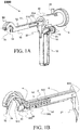
- FIG. 1A presents an external view of the circular bone tunneling device / adjustable suture passer.
- a hollow elongate body forms the distal portion of the tool.
- the distal portion of the body comprises a hollow elongate body head 90 (refers hereinafter as head or hollow elongate body head ), which is curved downwards; as shown in the illustration, in preferred embodiments, the head describes a rigid and an essentially semicircular arc, the concave side of the arc being on the underside.
- the proximal portion is a shaft 50.
- the hollow elongate body is made from two separate pieces 51 and 52 which are joined together in the final step of the assembly of the body and the components that are found within.
- the body may be constructed of any suitable biocompatible material such as a hard inert polymer or metal.
- the distal end of the head contains an orifice through which a rigid circular hollow tube 34 passes.
- the rigid circular hollow tube comprises at its distal end a mechanism 30 by which connection can be made with an appropriately-sized surgical needle or lance 32 , and is disposed within the head such that it can move back and forth and extend a sufficient distance from the end of the head such that the needle or lance can describe an essentially circular path through a circle of diameter equal to that of the arc described by the head.
- Means by which a surgical needle or lance can be attached to the end of the rigid circular hollow tube are well-known in the art.
- the tool further comprises an extendable and retractable support element 54 that, when extended, will grasp the bone on a second point along the circumference of the bone, other that of the needle.
- an extendable and retractable support element 54 that, when extended, will grasp the bone on a second point along the circumference of the bone, other that of the needle.
- the driving mechanism of the tool is housed within driving mechanism housing 10 attached to the proximal end of the body.
- the control and mechanisms are located within the driving mechanism housing.
- a handle 12 is attached to the underside of the tool, either to the body or to the driving mechanism housing or to both.
- the movements of the hollow tool and the support element are controlled by independent control and driving systems. In the view shown in FIG. 1A , some of the elements of these control and driving systems are visible.
- Rotatable handle 18 is connected to the driving mechanism for the rigid circular hollow tube such that the motion of the distal end of the rigid circular hollow tube is proportional to the angle through which the handle is turned.
- Activation of quick-release tab 20 causes the rigid circular hollow tube to move directly to the end of its travel. Also visible in FIG.
- Rotatable knob 14 is connected to the driving mechanism of the support element such that the degree to which it is extended is proportional to the angle through which the knob is turned.
- Rotatable knob 18 comprises a central threaded orifice that engages threaded rod 24 ; as the knob is turned, it moves down the length of the threaded rod.
- the control mechanism also includes tab 22 which physically engages the driving mechanism for the support element.
- the tab includes an orifice that fits over the threaded rod distally to knob 14 and a stiff connector that connects the orifice to the distal end of the tab.
- the support element control mechanism also includes a quick-release pin 16 , activation of which enables the support element to move directly to the end of its travel.
- one side of the shaft includes a window 512 .
- the rigid circular hollow tube driving mechanism includes a mark or other indicator 604 that is visible through the window and indicates the current position of the rigid circular hollow tube relative to the bounds of its travel.
- a mark 514 is placed on the body; when indicator 604 reaches mark 514 , the user knows that the rigid circular hollow tube has reached the end of the travel.
- the driving mechanism for the rigid circular hollow tube comprises a series of slidable members (beads) attached to one another.
- the interior of the body includes on its upper or lower side or both a track 522 that guides the movement of the slidable members.
- the distal slidable member 4 is flat on its forward side, which engages the proximal end of the hollow tube.
- the remaining slidable members 2 need not be flat on the forward side; as described in detail below, in preferred embodiments, they present a substantially circular profile.
- the driving mechanism also includes at its proximal end rigid circular hollow tube actuator 6 that engages the rigid circular hollow tube control such that when the rigid circular hollow tube control moves forward, it causes the activator to move forward, thereby causing the slidable members to slide distally, pushing the hollow tube.
- the support element activating mechanism comprises an actuator 58 that engages at its proximal end the distal end of the support element control, and at its distal end support element connecting yoke 56 whereby forward movement of the support element control forces forward movement of actuator 58 (along axis 582 ) and hence forward movement of connecting yoke 56.
- the connecting yoke is pivotally connected to the support element via pivot element (e.g. a pin around which the assembly can rotate) 562. When activated, the support element moves along axis 542. It should be emphasized that the distal end of the support element, when activated, is located along the path formed by the rigid circular arc.
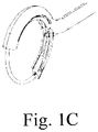
- a circular cross section/profile of the shaft is provided.
- the circular profile ensures the best adhering/ joining of the two parts of the incision (through which the circular tunneler/suture passer is being inserted).
- Such profile significantly reduces any leakage (of e.g. saline, which is typically used by surgeons to expand the inner volume) that may be developed during the operation.
- the rigid circular hollow tube driving mechanism described above can provide a force of several hundred Newtons (especially, in the range of about 500 to about 600 Newton) to the hollow tube, which is more than sufficient for the rigid circular hollow tube to penetrate bone.
- the tool comprises an extendable/retractable support element which, when extracted, extends from the underside of the tool opposite to the head.
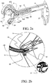
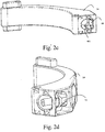
- FIGs. 2a and 2b shows embodiment 1000 of the tool after the support element 54 has been extended.
- the support element additionally comprises a needle extractor 60.
- the needle extractor 60 is responsible for maintaining penetrating element 32 within the support element 54. The same is enabled by means of a bore 601 located within the support element 54, into which the needle extractor 60 penetrates so as to prevent the departure of penetrating element 32 from the support element 54.
- Penetrating element 32 is a sharp element that can be pushed into the bone and penetrate through it. Penetrating element 32 pulls wire 130 with it ( 130 is connected to the proximal end of 32 ).
- needle extractor 60 remains within the bore 601 [while the arched rigid hollow tube 34 returns back to housing 90.
- Needle extractor 60 enables the penetrating element 32 to enter into support element 54 yet, ensures its release from the rigid circular hollow tube 34 when the same moved reversibly back into head.
- Needle extractor 60 is an elastic element, bendable in one direction yet stiff in the opposite direction.
- Embodiment 1000 (illustrated in Fig. 1 ) discloses needle extractor 60 as a rigid hook rotating on an axis with a torsion spring pushing it.
- the mechanical properties of the needle extractor 60 namely, its elasticity and spring-like properties
- the mechanical properties of the needle extractor 60 can be exploited.
- Figs. 2c and 2d illustrates an embodiment in which the spring-like properties of the needle extractor 60 is utilized.
- the needle extractor 60 may be integrated into support element's 54 internal surface.
- the needle extractor 60 is characterized by two configurations, an extended configuration and a retracted configuration.
- the needle extractor 60 substantially reduces the support element's 54 inner diameter; and, in the retracted configuration of the needle extractor 60 , the support element's 54 inner diameter remains substantially the same.
- the needle extractor 60 Due to the needle extractor's 60 spring-like properties, it can be reconfigured from the extracted configuration to the retracted configuration by application of force on the same. Once no force is applied, the needle extractor 60 is reconfigured back from the retracted configuration to the extended configuration.
- the default configuration of the needle extractor 60 is the extended configuration, in which the inner diameter of support element 54 is reduced.
- the needle extractor 60 is reconfigured from the extended configuration to the retracted configuration and applies pressure on the penetrating element 32, ⁇ so as to maintain the same within support element 54.
- the support element 54 may comprise either one or a plurality of said needle extractor 60.
- Fig. 2d illustrates the above mentioned embodiment, but with the penetrating element 32 integrated within the support element 54.
- Fig. 2b illustrates a close up view of how the needle extractor 60 functions once penetrating element (e.g., needle or lance) 32 are within the support element 54 and after the rigid circular hollow tube 34 is withdrawn back .
- penetrating element e.g., needle or lance
- distal face of element 54 is equipped with prongs 62 , adapted to prevent any movement of the support element 54 , once the same is positioned at desired location.
- the needle extractor is disposed on the underside of the support element and comprises a hollow receptacle into which the penetrating element (needle or lance) 32 enters upon reaching circumference point 2.
- the penetrating element remains within hollow receptacle of the needle extractor 60.
- FIG. 3 shows a cross-sectional view of embodiment 1000 of the tool after the rigid circular hollow tube has completed its travel.
- a guide wire 130 passes through the rigid circular hollow tube and is attached to the proximal end of the lance 32 (which in this view has passed through the bone, shown as a shaded region in the figure).
- a suture can then be attached to the distal end of the guide wire and passed through the soft tissue and into and through the bone.
- the needle has entered into the bore 601 in the support element 54.
- FIG. 4 shows a cross-sectional view of the tool after the support element has been retracted.
- the rigid circular hollow tube is still within the bone, and needle can be seen to have remained within the needle extractor, carrying guide wire 130 with it.
- a cavity in retractable support element 54 provides a 'nesting volume' for the penetrating element 32 securing it to its position, so as to prevent any damage to surrounding tissues.
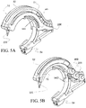
- FIGs. 5A-5D illustrate the distal end of another preferred embodiment of the tool.
- an additional radial support is provided to rigid circular hollow tube 34 sections that aren't yet within the bone in order to ensure that at the end of its travel it will engage needle extractor 60.
- the support element further comprises a tab 5421 that protrudes through a slot 5422 in one side of the head ( 90 ).
- Tab 5421 slides in a slot 5422 so as to indicate the current position of the rigid circular hollow tube relative to the bounds of its travel.
- this embodiment further includes rigid support element 70.
- the support element is located between the right and left halves of the head; in a preferred embodiment of the device, the head and body are manufactured from two matching pieces that form the left and right halves of the device when it has been assembled.
- FIG. 5A shows an external view of head 90, including rigid support element 70. The same illustrating how it sits between the two halves of the head.
- FIG. 5B shows a partial cutaway view of the head with support element 70 in place.
- An isometric view of rigid support element 70 can be seen in FIG. 5C .
- Support element 70 has the shape of an arc with essentially the same curvature as the upper portion of head 90. Slots on either side of the support element hold it in place between the two halves of the head when it is assembled.
- Support element 70 has a depth sufficient to contact rigid circular hollow tube 34 while not hindering the movement of the hollow tube.
- Rigid support element thus provides additional support to rigid circular hollow tube 34 and prevents it from bending or crimping (and any other deformation) such that the rigid circular hollow tube is constrained to move only along a path that will return it to needle catcher 60, as shown in FIG. 5D and Fig. 6D
- the slidable member is substantially cylindrical in shape, with an indentation 204 around the waist of the cylinder (i.e. around its circumference and perpendicular to the cylinder's longitudinal axis).
- the indentation allows guide wire 130 to pass unhindered.
- At least one of the ends 202 fits into track 522 that enables the member to slide along the distal-proximal axis of the body. Note that even though the member has a circular cross-section, it does not roll along the track.
- a channel 206 passes through the slidable member along an axis substantially perpendicular to the longitudinal axis of the cylinder.
- a connecting wire 132 disposed along the proximal-distal axis of the body, passes through the channel, thereby connecting the plurality of slidable members.
- the connecting wire is formed into a loop, the proximal end of which engages the rigid circular hollow tube driving mechanism, enabling the rigid circular hollow tube to be retracted after the tool has been used.
- guide wire 130 the leg of the loop in connecting wire 132 that does not pass through the channel passes outside the slidable member via indentation 204.
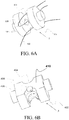
- FIG. 6B illustrates a preferred embodiment of distal slidable member 4.
- the overall cylindrical shape 402, indentation 404, and channel 406 are analogous to components 202, 204, and 206 of slidable member 2 illustrated in FIG. 5A .
- the distal slidable member directly engages/actuates rigid circular hollow tube 34.
- it is provided with a flat face 410 that is oriented facing forward (i.e. in the direction of motion toward head 90 ), and a channel 408 that fits over the proximal end of rigid circular hollow tube 34 and, in preferred embodiments, is physically connected thereto.
- slidable members 2 have a somewhat different configuration from that shown in FIG. 6A .
- the configuration of slidable member 2 in these embodiments is shown in FIG. 6C . While the slidable member retains its generally cylindrical shape, the indentation is no longer symmetrical about the axis of the cylinder. Rather, indentation 2004 is cut through most of the diameter of the cylinder so that the slidable member 2 may pass under support element 70. Consequently, channel 2006 adapted to allow passage of connecting wire 132 is displaced from the center, as shown in the diagram. A second indentation 2008 is made on the opposite side of the member to allow passage of guide wire 130.
- FIG. 6D A schematic assembly diagram showing support member 70, slidable member 2, and rigid circular hollow tube 34 in its extended position (i.e. after the needle attached to it has reached needle catcher 60 ), is given in FIG. 6D .
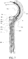
- FIG. 7 presents a cross-sectional view of the assembly of the rigid circular hollow tube driving mechanism according to one embodiment of the invention.
- the slidable members are connected via connecting wire 132 through orifices 206 and 406 to form a train.
- Connecting wire 132 loops back through indentations 204 and 404 ; the proximal end of the loop engages the rigid circular hollow tube control such that when the rigid circular hollow tube control is activated, the slidable members move in tandem, thereby moving the rigid circular hollow tube 34 and the needle or lance 32 connected to its distal end.
- Guide wire 130 passes through indentations 204 and 404 , whereby motion of the guide wire, which as described above passes through the rigid circular hollow tube 34 and is connected to needle or lance 32, is unimpeded.
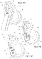
- FIG. 8 presents isometric views of the hollow tube (driving mechanism) control according to a preferred embodiment of the invention.
- Rotatable knob 18 comprises a substantially circular handle (in preferred embodiments, it is knurled or its circumference is provided with a plurality of indentations or protrusions for ease of handling) and a hollow shaft 186 the internal wall of which is threaded.
- Driving mechanism housing 10 comprises a channel of internal diameter appropriate to provide a slip fit to hollow shaft 186 and a distal wall with an orifice through which hollow tube actuator 6 passes.
- the threaded shaft further comprises a groove 182 around the circumference of its external wall, substantially perpendicular to the longitudinal axis of the shaft, and disposed substantially at its distal end.
- the threaded hollow shaft engages a threaded rod 602 which is physically connected to the proximal end of hollow tube actuator 6.
- a hollow tube driving mechanism release tab 20 is pivotably connected to the body of driving mechanism housing 10.
- the hollow tube driving mechanism release tab comprises two protrusions extending from the central pivoting body, one of which ( 212 ) engages groove 182 and one of which extends above driving mechanism housing 10 used for handling.
- FIG. 8A shows a view of the hollow tube control as it appears when the driving mechanism release tab 20 is in its engaged position.
- protrusion 212 prevents handle 18 from moving along the distal-proximal axis of the body, so rotation of the handle causes threaded rod 602 to travel along the length of the shaft, thereby driving hollow tube actuator 6 and, via the remainder of the hollow tube driving mechanism (not shown in FIG. 8 ) engaged by actuator 6, slidable member (e.g., 2 and 4) and hollow tube 34 such that the distance through which the hollow tube moves is proportional to the angle through which knob 18 is rotated.
- the threaded rod is shown at the most distal point of its travel; further movement of the threaded rod is blocked by the distal wall of driving mechanisms housing 10.
- FIG. 8B shows the hollow tube control with tab 20 in its disengaged position. Since in this configuration motion of knob 18 along the distal-proximal axis of the tool is unhindered, it is possible in this case to move hollow tube 34 by pushing or pulling knob 18 without turning it. By pulling knob 18 to the proximal direction hollow tube 34 is retrieved back into 90.
- FIG. 9 presents isometric views illustrating the support element control according to a preferred embodiment of the invention.
- FIG. 9A shows an external view
- FIGs. 9B and 9C illustrated the internal mechanism of the support element control with handle 12 removed.
- the support element control illustrated in FIG. 9 it comprises a threaded rod 24 and a quick-release pin 16.
- Quick-release pin 16 is adapted such that when it is in its disengaged position (as in FIG. 9B ), motion of the threaded rod (both axial and rotational) is blocked, while when it is in its engaged position (as in FIG. 9C ), motion of the threaded rod is permitted.
- the support element control further comprises rotatable knob 14, which comprises an internally-threaded orifice that engages the threads of threaded rod 24.
- rotatable knob 18 in the most preferred embodiments, the circumference of knob 14 is knurled or provided with a plurality of indentations or protrusions for ease of handling.
- the control also comprises a slider, which comprises a tab 22, a circular orifice 26 of internal diameter at least sufficient to provide a slip fit over threaded rod 24, and a rigid connector that attaches the orifice to the tab.
- Tab 22 comprises a portion 27 that slides along the underside of shaft 50 and a protrusion that extends below the shaft.
- the underside of shaft 50 comprises a slot that allows the protrusion to move freely along the proximal-distal axis of shaft 50; in other embodiments, shaft 50 comprises a track on the exterior of its underside in which tab 22 and those portions of the support element driving mechanism engaged thereby slide.
- knob 14 engages the support element driving mechanism as follows.
- knob 14 travels along the length of threaded rod 24.
- the knob will engage orifice 26, thereby causing tab 22 to move in the distal direction.
- the proximal end of the support element driving mechanism e.g. actuator 58
- knob 14 is turned in the opposite direction, causing it to travel proximally along threaded rod 24. This motion will then leave a gap between knob 14 and orifice 26.
- Tab 22 can then be moved in the proximal direction manually by application of pressure to the portion that extends beneath shaft 50.
- quick-release pin 16 when quick-release pin 16 is in its engaged position, it prevents threaded rod 24 from moving, either by physically holding it (e.g. via a retractable vise-like grip) or by engaging an indentation in the threaded rod.
- pin 16 When pin 16 is disengaged, as shown in FIG. 9C , it no longer prevents movement of threaded rod 24.
- engagement of the quick-release pin permits the user to manually move the support element control without the necessity of turning knob 14.
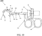
- FIG. 10 shows a view of a second embodiment 2000 of the circular tunneler/adjustable suture passer herein disclosed.
- the embodiment shown in FIG. 10 incorporates additional embodiments of the hollow tube and support element driving mechanisms and of the support element driving mechanism.
- shaft 50 incorporates a body slot along at least part of the length of at least one side of the body
- head 90 incorporates head slot 390 along at least part of the length of at least one side of the head.
- Slider 310 engages the hollow tube control at its proximal end.
- Yoke 300 is pivotably connected to slider 310 by pin 320 that passes through the body slot, and is pivotably connected to the proximal end of hollow tube 34 by pin 324 that passes through head slot 390.
- the hollow tube control When the hollow tube control is engaged, slider 310 travels distally, whereby yoke 300 forces hollow tube 34 to travel distally in proportion to the distance through which slider 310 has traveled.
- the hollow tube control further comprises bearing housing 330.
- FIG. 10 also shows a second embodiment of the support element driving mechanism.
- the support element driving mechanism comprises an actuator 58 that engages at its proximal end the support element control and that is pivotably connected substantially at its distal end to a yoke 340 via a pin (not shown in FIG. 10 ).
- Yoke 340 is pivotably connected substantially at its distal end to the support element.
- actuator 58 travels distally, whereby yoke 340 moves downward, causing the support element to extend.
- handle 12 comprises two portions, a movable distal portion 12A and a stationary proximal portion 12B.
- the handle is designed such that the user can grip it by placing his or her fingers through orifices at the bottom of the two portions of the handle.
- the movable distal portion of the handle further comprises a tab that fits into a slot in the underside of shaft 50.
- the support element control comprises the movable portion of the handle, which engages actuator 58; in preferred embodiments, the two are physically connected. As the movable portion of the handle is moved, actuator 58 moves in tandem, forcing yoke 340 to move and thereby extending or retracting the support element.
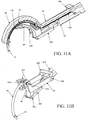
- FIG. 11 shows views of the interior of the distal end of the circular tunneler/adjustable suture.
- the view shown in FIG. 11A illustrates how guide wire 130 passes through the head and shaft, and how the hollow tube actuator 58 engages yoke 340.
- FIG. 11B illustrates the workings of the support element driving mechanism according to this embodiment When actuator 58 moves distally, it engages yoke 340. Substantially at its distal end, the yoke is connected to support element 54 via bearing 332. As the yoke descends in tandem with the motion of the actuator, the support element is pulled downward and forward, thus extending into its working position.
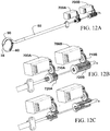
- FIG. 12 presents a schematic illustration of an embodiment in which the hollow tube control and support mechanism control are actuated electrically.
- Motor 700 engages at least one of rotatable knobs 14 and 18. In the embodiment shown in the figure, each of the two rotatable knobs is engaged by a motor; motor 700A engages rotatable knob 14 and motor 700B engages rotatable knob 18. Any type of motor known in the art appropriate for actuating a medical device may be used. In preferred embodiments, motors 700A and 700B are DC stepper motors, FIG. 12A shows an overall schematic of such an embodiment. FIG. 12B presents a closer view of the hollow tube and support element controls.
- each rotatable knob comprises a gear 720 ( 720A and 720B ).
- Motors 700 ( 700A and 700B ) drives gear 710 ( 710A and 710B, respectfully), which in turn drives gear 720 ( 720A and 710B, respectfully).
- FIG. 12C presents a cutaway view of the two rotatable knobs, illustrating the internal threads of the knobs and the threaded rods that the knobs engage, showing how the motor actuates the control mechanisms.
- Said gearing elements basically transforms the motors rotational input into two axial,linear, independent and juxtaposed moves.
- it further comprises a tendon holder.
- a tendon holder Any tendon holder known in the art that can be adapted for use with the present invention may be used.
- the term "tendon holder” refers hereinafter to any device which enable the grasping of a tendon and pass of a suture through the same.
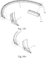
- FIG. 13 illustrates a preferred embodiment of a tendon holder especially adapted for use with the invention herein disclosed.
- FIG. 13A presents a view of the distal portion of the circular bone tunneling device / suture passer showing the tendon holder.
- the tendon holder comprises grasping member 800, slider 810, and manipulator 820.
- the tendon holder may comprise a single manipulator that enables both pushing and/or pulling movements.
- the slider is attached to the hollow elongate body of the circular tunneler/suture passer such that it can slide back and forth along the body.
- it can comprise a channel with internal dimensions chosen to provide a slip fit over the body.
- Manipulator 820 is attached to the proximal side of the slider and sits on the upper side of the body. As can be seen in the diagram, in preferred embodiments, the manipulator has an ergonomic shape such that it can be pushed and pulled by the thumb of the operator of the device.
- Grasping member 800 is attached to the distal side of the slider.
- the elongate body is disposed on the upper side of the elongate body and slides along the distal-proximal axis of the body on the upper side of the body and passes under the head at the point at which the head is attached to the body.
- it has an elongated shape (e.g. a parallelepiped that is wider than it is high) and has a length sufficient that when it is moved to the distal end of its travel, it reaches sufficiently close to the distal end of head 90 that a tendon can be grasped between the distal end of the grasping member and the underside of the head.
- FIG. 13B An overall view of an embodiment 3000 of the device that comprises a tendon holder is shown in FIG. 13B .
- the present disclosure also provides a method for tunneling through a bone during arthroscopic surgery.
- the method comprises steps of (a) providing a curved bone tunneling device comprising: (i) a hollow elongated body defining a rigid circular arc; said hollow elongated body comprising a surgical needle adapted to tunnel through a bone along a path formed by said circular arc; and, (ii) an extendable and retractable support element, reconfigurable from at least one extended configuration to at least one retracted configuration; (b) positioning said hollow elongated body of said device adjacent to the circumference of a bone; (c) fixating said needle to said bone; (d) extending said retractable support element to a location along the path formed by said circular arc; thereby grasping said bone with said support element and said hollow elongated body at two points along the circumference of said bone; (e) actuating said hollow tube and said needle, thereby tunneling through said bone along said circular arc path; wherein said step of tunneling through said bone
- the present disclosure also provides a method for attaching soft tissue such as a ligament to a bone without the use of an anchor.
- the method comprises the following steps.
- a guide wire is passed through a device capable of imparting sufficient force to a surgical needle such that the surgical needle will pass through bone.
- a surgical needle or lance is attached to the guide wire and then connected to the distal end of the device.
- the device is then inserted into position.
- a support element engages the bone through which the needle is to be inserted on a side of the bone opposite that into which the needle is to be engaged, i.e. it holds the bone from the side towards which it would tend to move when the needle hits the bone's surface.
- the device is then engaged, causing the needle (and the guide wire attached thereto) to pass through the bone.
- a suture is attached to the proximal end of the guide wire.
- the guide wire is pulled through the bone, carrying the suture with it. Once the suture has passed through the bone, the guide wire is detached and discarded
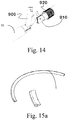
- Fig. 14 illustrates an embodiment in which the decoupling of the shaft ( 50 ) is enabled.
- FIG. 14 presents a schematic view of a connector for rapid connection and disconnection of the shaft.
- a connector is particularly useful for embodiments that comprise motorized control.
- the circular bone tunneling device mechanically driven by one or more motors
- it may include a connector for rapid connection and disconnection of the working portion of the circular bone tunneling device / suture passer (i.e. the head and the elongate body) from the shaft that contains the hollow tube and support mechanism controls.
- the connector is hollow to allow physical connection of the control and driving mechanisms within the same, and comprises at least one pivotable joint 900.
- the pivotable joint 900 comprises a slot, a fixed acceptor 910 with a pin adapted to match the slot, and a slidable closure 920 that slides over the joint and pin after the connection is made (so as to fix the connection).
- one of the needle's critical properties is the length of the needle used. If the needle used is too long, changing the direction of the penetration path by the hollow tube would be resisted and difficult to achieve.
- the needle is a straight needle or slightly curved needle.
- the cross sectional area of the needle is selected from a group consisting of circular, triangular, rectangular or any combination thereof.
- the hollow tube's outer diameter is in the range of about 1 to about 3mm; According to another embodiment, the internal diameter (through which the guide wire passes) is in the range of about 0.5 to about 1.5 mm; or any combination thereof.
- Fig. 17 illustrating both the internal diameter (illustrated as numerical reference 1701 ) of the hollow tube and the outer diameter (illustrated as numerical reference 1702 ) of the same. Also illustrated in the figure is the radius of curvature (illustrated as numerical reference 1703 ). According to one embodiment of the present invention the radius of curvature 1703 is in the range of about 7.5 mm to about 15mm, especially 12.5 mm.
- the surgical rigid hollow tube is made of biocompatible metal selected from hardened corrosion resistant steel.
- FIG. 15a illustrating a hollow tube 34 having a triangular cross-section.
- wire 130 is threaded through the hollow tube 34.
- the hollow tube 34 and the surgical needle comprises a groove along said needle's circumference (incase the cross section of said hollow tube is circular) or along at least one of said hollow tube's rib (in case the cross section is triangular or rectangular) throughout which said wire 130 is threaded. It should be understood to one skilled in the art, that the formation of a groove along one of the circumference or ribs simplifies the production line of the same. Reference is now made to Fig. 15b illustrating such an embodiment. According to this embodiment wire 130 is along groove 1500.
- one of the triangle's vertexes is pointing towards the center of the circular arc. Such an embodiment will ensure minimal resistance during the penetration into the bone.
- Figs. 16a-16b illustrating another embodiment in which the needle 32 being used is a slightly curved needle.
- Such curved needle ensures the mating and the slip fit between the needle, 32, and the support element 54 and further allows the needle and hollow tube to move in the direction of the arc.
- Fig. 16b also illustrates an embodiment in which the hollow tube 34 comprises a grove 1500 along which said wire 130 is threaded.
Claims (7)
- Kreisknochentunnelierungsvorrichtung (1000) zur Verwendung in der arthroskopischen Chirurgie, umfassend:einen hohlen länglichen Körper (51, 52), der einen hohlen länglichen Körperkopf (90) umfasst, wobei der hohle längliche Körperkopf (90) einen starren Kreisbogen definiert; wobei der hohle längliche Körperkopf (90) eine chirurgische Nadel (32) umfasst, die durch einen Knochen entlang eines Pfads tunnelieren kann, der durch den starren Kreisbogen ausgebildet ist; undein ausziehbares und einziehbares Trägerelement (54), das aus wenigstens einer ausgezogenen Konfiguration an wenigstens eine eingezogene Konfiguration rekonfigurierbar ist;wobei das Trägerelement (54) in der ausgezogenen Konfiguration entlang des durch den starren Kreisbogen ausgebildeten Pfads positioniert werden kann; undwobei ferner das Trägerelement (54) in der ausgezogenen Konfiguration und der hohle längliche Körperkopf (90) den Knochen von mindestens zwei Punkten entlang des Umfangs des Knochens greifen können;dadurch gekennzeichnet, dass die Vorrichtung ferner folgendes umfasst:einen Trägerelementantriebsmechanismus, der bei Aktivierung eines Trägerelementreglers die Bewegung des Trägerelements (54) antreiben kann;eine starre, runde, hohle Röhre (34), die umkehrbar an der Nadel (32) angebracht werden kann und die wenigstens einen Führungsdraht (130) tragen kann, wobei die starre, runde, hohle Röhre beweglich wenigstens teilweise in dem hohlen länglichen Körper (51, 52) angeordnet ist, so dass die starre, runde, hohle Röhre (34) sich entlang der proximal-distalen Richtung des Körpers (51, 52) und durch eine Öffnung in dem hohlen länglichen Körperkopf (90) bewegen kann; undeinen Antriebsmechanismus für die starre, runde, hohle Röhre, der von dem Trägerelementantriebsmechanismus unabhängig ist, wobei er die Bewegung der starren, runden, hohlen Röhre steuern kann, wobei der Antriebsmechanismus für die starre, runde, hohle Röhre folgendes umfasst:wenigstens eine Spur (522), die sich entlang einer distal-proximalen Achse des hohlen länglichen Körpers (51, 52) in dem hohlen länglichen Körper (51, 52) befindet;einen Verbindungsdraht (132), der in dem hohlen länglichen Körper (51, 52) eine Schlaufe bildet, wobei das proximale Ende der Schlaufe physisch mit dem Antriebsmechanismus für die starre, runde, hohle Röhre verbunden ist;ein distales verschiebbares Element (4), das sich in der Spur (522) befindet und entlang der Spur (522) gleiten kann, während der Führungsdraht (130) und ein Schenkel der Schlaufe, der durch den Verbindungsdraht (132) gebildet wird, ungehindert durch den hohlen länglichen Körper (51, 52) treten können, wobei das distale verschiebbare Element (4) folgendes umfasst:eine im Wesentlichen flache distale Kante; undeinen Kanal (206), der durch das distale verschiebbare Element (4) verläuft, durch welches der zweite Schenkel der durch den Verbindungsdraht (132) gebildeten Schlaufe verläuft;eine Mehrzahl weiterer verschiebbarer Elemente (2), die sich in der Spur (522) befinden und entlang der Spur (522) gleiten können, während der Führungsdraht (130) und ein Schenkel der durch den Verbindungsdraht (132) gebildeten Schlaufe ungehindert durch den hohlen länglichen Körper (51, 52) treten können, wobei jedes der weiteren verschiebbaren Elemente (2) einen Kanal umfasst, durch den der zweite Schenkel der durch den Verbindungsdraht (132) gebildeten Schlaufe verläuft; undeinen Aktuator (6) für die starre, runde, hohle Röhre, der sich in dem Körper (51, 52) proximal zu dem am proximalsten angeordneten verschiebbaren Element (2) befindet, wobei der Aktuator (6) so angeordnet ist, dass er mit dem Antriebsmechanismus für die starre, runde, hohle Röhre eingreift; wobei die verschiebbaren Elemente (2, 4) während dem arthroskopischen chirurgischen Eingriff ein konstantes Werkzeugprofil bereitstellen, wobei die verschiebbaren Elemente (2, 4) jeweils die Form eines Zylinders mit einer Vertiefung (204) um deren Umfang aufweisen, wobei der Kanal (206) durch den Zylinder in der Vertiefung (204) im Wesentlichen senkrecht zu der Längsachse des Zylinders verläuft.
- Kreisknochentunnelierungsvorrichtung (1000) nach Anspruch 1, wobei die chirurgische Nadel (32) eine steife chirurgische Nadel ist.
- Kreisknochentunnelierungsvorrichtung (1000) nach Anspruch 1, wobei bei Aktivierung des Antriebsmechanismus für die starre, runde, hohle Röhre die starre, runde, hohle Röhre (34) distal entlang eines allgemein gekrümmten Pfads bewegt wird, so dass sie den Knochen penetriert; wobei ferner bei Aktivierung des Trägerelements (34) dieses ausgezogen wird, so dass der Knochen durch das ausziehbare und einziehbare Trägerelement (34) und den Kopf (90) gegriffen wird.
- Kreisknochentunnelierungsvorrichtung (1000) nach Anspruch 1, wobei das ausziehbare und einziehbare Trägerelement (34) ferner einen Nadelextraktor (60) umfasst.
- Kreisknochentunnelierungsvorrichtung (1000) nach Anspruch 1, ferner umfassend:ein Antriebsmechanismusgehäuse (10); undein Lagergehäuse (330), und wobeider hohle längliche Körper (51, 52) einen Schaft (50) umfasst,wobei sich das Lagergehäuse (330) zwischen dem Antriebsmechanismusgehäuse (10) und dem Schaft (50) befindet.
- Kreisknochentunnelierungsvorrichtung (1000) nach Anspruch 5, wobei diese zusätzlich einen Griff (12) umfasst, der wenigstens an dem Antriebsmechanismusgehäuse (10) oder dem Schaft (50) angebracht ist.
- Kreisknochentunnelierungsvorrichtung (1000) nach Anspruch 1, wobei diese zusätzlich wenigstens einen Trägerelementregler umfasst, der die Bewegungen des Trägerelementantriebsmechanismus regelt.
Applications Claiming Priority (2)
| Application Number | Priority Date | Filing Date | Title |
|---|---|---|---|
| US36324710P | 2010-07-11 | 2010-07-11 | |
| PCT/IL2011/000549 WO2012007941A2 (en) | 2010-07-11 | 2011-07-11 | Circular bone tunneling device |
Publications (3)
| Publication Number | Publication Date |
|---|---|
| EP2590580A2 EP2590580A2 (de) | 2013-05-15 |
| EP2590580A4 EP2590580A4 (de) | 2017-06-07 |
| EP2590580B1 true EP2590580B1 (de) | 2019-05-08 |
Family
ID=45469866
Family Applications (1)
| Application Number | Title | Priority Date | Filing Date |
|---|---|---|---|
| EP11806391.6A Not-in-force EP2590580B1 (de) | 2010-07-11 | 2011-07-11 | Kreisförmige knochentunellierungsvorrichtung |
Country Status (11)
| Country | Link |
|---|---|
| US (2) | US9770248B2 (de) |
| EP (1) | EP2590580B1 (de) |
| JP (1) | JP5881696B2 (de) |
| KR (1) | KR101805448B1 (de) |
| CN (1) | CN103221080B (de) |
| AU (1) | AU2011277949B2 (de) |
| BR (1) | BR112013000707A2 (de) |
| CA (1) | CA2804255C (de) |
| ES (1) | ES2741174T3 (de) |
| IL (1) | IL224079A (de) |
| WO (1) | WO2012007941A2 (de) |
Families Citing this family (56)
| Publication number | Priority date | Publication date | Assignee | Title |
|---|---|---|---|---|
| US7846183B2 (en) | 2004-02-06 | 2010-12-07 | Spinal Elements, Inc. | Vertebral facet joint prosthesis and method of fixation |
| US9504583B2 (en) | 2004-06-10 | 2016-11-29 | Spinal Elements, Inc. | Implant and method for facet immobilization |
| US8992533B2 (en) * | 2007-02-22 | 2015-03-31 | Spinal Elements, Inc. | Vertebral facet joint drill and method of use |
| US8652137B2 (en) | 2007-02-22 | 2014-02-18 | Spinal Elements, Inc. | Vertebral facet joint drill and method of use |
| BR112013000707A2 (pt) | 2010-07-11 | 2016-05-24 | Mininvasive Ltd | "dispositivo de escavação óssea circular e método para escavação através de um osso durante cirurgia artroscópica" |
| US9271765B2 (en) | 2011-02-24 | 2016-03-01 | Spinal Elements, Inc. | Vertebral facet joint fusion implant and method for fusion |
| US8740949B2 (en) | 2011-02-24 | 2014-06-03 | Spinal Elements, Inc. | Methods and apparatus for stabilizing bone |
| EP2741680A4 (de) * | 2011-08-08 | 2015-07-08 | Endoevolution Llc | Vorrichtung und verfahren für minimal-invasives chirurgisches nähen |
| KR101917873B1 (ko) | 2011-08-24 | 2018-11-13 | 미닌베이시브 리미티드 | 관절경 수술 장치 |
| US9820754B2 (en) | 2011-08-24 | 2017-11-21 | Mininvasive Ltd. | Circular bone tunneling device employing a stabilizing element |
| USD739935S1 (en) | 2011-10-26 | 2015-09-29 | Spinal Elements, Inc. | Interbody bone implant |
| US9782165B2 (en) | 2011-11-11 | 2017-10-10 | VentureMD Innovations, LLC | Transosseous attachment |
| US10136883B2 (en) | 2011-11-16 | 2018-11-27 | VentureMD Innovations, LLC | Method of anchoring a suture |
| US10470756B2 (en) | 2011-11-16 | 2019-11-12 | VentureMD Innovations, LLC | Suture anchor and method |
| US10675014B2 (en) | 2011-11-16 | 2020-06-09 | Crossroads Extremity Systems, Llc | Knotless soft tissue attachment |
| US10548585B2 (en) | 2011-11-16 | 2020-02-04 | VentureMD Innovations, LLC | Soft tissue attachment |
| WO2013087095A1 (en) * | 2011-12-13 | 2013-06-20 | Ethicon Endo-Surgery, Inc. | An applier for anchoring a lining to a hollow organ |
| AU2013207071B2 (en) | 2012-01-08 | 2018-03-29 | Mininvasive Ltd. | Arthroscopic surgical device |
| US9427226B2 (en) * | 2012-03-14 | 2016-08-30 | Ethicon Endo-Surgery, Llc | Laparoscopic suturing instrument with rack drive |
| CN102824200B (zh) * | 2012-09-17 | 2014-12-24 | 北京中法派尔特医疗设备有限公司 | 一种可自动打荷包的圆形荷包钳 |
| CN102813538B (zh) * | 2012-09-17 | 2014-12-03 | 北京中法派尔特医疗设备有限公司 | 一种可自动打荷包的圆形荷包钳 |
| US9687221B2 (en) | 2013-02-13 | 2017-06-27 | Venture MD Innovations, LLC | Method of anchoring a suture |
| WO2014128699A1 (en) | 2013-02-20 | 2014-08-28 | B-Nano Ltd. | Scanning electron microscope |
| USD765853S1 (en) | 2013-03-14 | 2016-09-06 | Spinal Elements, Inc. | Flexible elongate member with a portion configured to receive a bone anchor |
| US9421044B2 (en) | 2013-03-14 | 2016-08-23 | Spinal Elements, Inc. | Apparatus for bone stabilization and distraction and methods of use |
| US9820784B2 (en) | 2013-03-14 | 2017-11-21 | Spinal Elements, Inc. | Apparatus for spinal fixation and methods of use |
| US9820755B2 (en) | 2013-03-15 | 2017-11-21 | Zimmer Biomet CMF and Thoracic, LLC | Sternal closure cerclage, plate implant and instrumentation |
| US10010359B2 (en) | 2013-03-15 | 2018-07-03 | Zimmer Biomet CMF and Thoracic, LLC | Sternal closure cerclage, plate implant and instrumentation |
| JP6626818B2 (ja) | 2013-03-18 | 2019-12-25 | ミニンヴェイシヴ リミティッド | 関節鏡視下手術装置 |
| ITMO20130206A1 (it) * | 2013-07-17 | 2015-01-18 | Ncs Lab S R L | Dispositivo perfezionato per l'inserimento trans osseo di fili di sutura. |
| CN103494623B (zh) * | 2013-08-30 | 2016-02-24 | 北京中法派尔特医疗设备有限公司 | 荷包钳及其缝合装置 |
| US9839450B2 (en) | 2013-09-27 | 2017-12-12 | Spinal Elements, Inc. | Device and method for reinforcement of a facet |
| US9456855B2 (en) | 2013-09-27 | 2016-10-04 | Spinal Elements, Inc. | Method of placing an implant between bone portions |
| CN104739465B (zh) * | 2013-12-31 | 2017-02-15 | 深圳市鹏瑞智能技术应用研究院 | 表皮缝合器 |
| CN105326532B (zh) * | 2014-08-08 | 2017-06-09 | 天津瑞贝精密机械技术研发有限公司 | 一种自动缝合的外科器械 |
| AU2015313815A1 (en) | 2014-09-09 | 2017-04-06 | Mininvasive Ltd. | Padded transosseous suture |
| US11478275B2 (en) | 2014-09-17 | 2022-10-25 | Spinal Elements, Inc. | Flexible fastening band connector |
| JP2018502693A (ja) | 2015-01-27 | 2018-02-01 | スパイナル・エレメンツ・インコーポレーテッド | 椎間関節インプラント |
| JP2018504989A (ja) * | 2015-02-13 | 2018-02-22 | ハートウェア、インコーポレイテッド | 複合トンネル穿孔器具 |
| WO2016157211A1 (en) * | 2015-03-27 | 2016-10-06 | Indian Institute Of Technology, Bombay | An automated needle holder and suturing device |
| US10820918B2 (en) | 2015-07-17 | 2020-11-03 | Crossroads Extremity Systems, Llc | Transosseous guide and method |
| US10154868B2 (en) * | 2015-07-17 | 2018-12-18 | Kator, Llc | Transosseous method |
| US9962174B2 (en) | 2015-07-17 | 2018-05-08 | Kator, Llc | Transosseous method |
| US10143462B2 (en) | 2015-08-04 | 2018-12-04 | Kator, Llc | Transosseous suture anchor method |
| CA2997050A1 (en) * | 2015-09-24 | 2017-03-30 | Mininvasive Ltd. | Arthroscopic surgical device |
| US10835234B2 (en) | 2015-12-31 | 2020-11-17 | Mininvasive Ltd. | Arthroscopic surgical device |
| KR101912516B1 (ko) * | 2017-02-16 | 2018-10-26 | 순천향대학교 산학협력단 | 확장 가능한 와이어 패서 |
| JP2021502875A (ja) * | 2017-11-14 | 2021-02-04 | イーガン・デザイン・エルエルシー | 電気的に溶接可能な縫合糸材料、ならびに、溶接された縫合糸ループおよび他の溶接された構造体を形成するための装置および方法 |
| CN108361334A (zh) * | 2018-01-16 | 2018-08-03 | 潘隽玮 | 一种基于机械传动的序贯递接穿引系统 |
| JP2022535698A (ja) | 2019-05-22 | 2022-08-10 | スパイナル・エレメンツ・インコーポレーテッド | 骨タイおよび骨タイ・インサータ |
| US11457959B2 (en) | 2019-05-22 | 2022-10-04 | Spinal Elements, Inc. | Bone tie and bone tie inserter |
| GB2590138B (en) | 2019-09-30 | 2023-08-02 | Gyrus Acmi Inc | Suturing apparatus and method |
| US11304733B2 (en) | 2020-02-14 | 2022-04-19 | Spinal Elements, Inc. | Bone tie methods |
| CN111481247B (zh) * | 2020-04-20 | 2021-04-06 | 广西壮族自治区人民医院 | 一种胃肠镜用缝合器及其操作方法 |
| KR102188958B1 (ko) | 2020-08-24 | 2020-12-09 | 주식회사 이지엔도서지컬 | 바스켓 구동기 및 이를 포함하는 수술 장치 |
| CN112568951B (zh) * | 2021-02-02 | 2021-11-09 | 山东省千佛山医院 | 空腔脏器镜联通管缝合机构 |
Family Cites Families (58)
| Publication number | Priority date | Publication date | Assignee | Title |
|---|---|---|---|---|
| US2579192A (en) * | 1950-08-15 | 1951-12-18 | George H Sciaroni | Suturing instrument |
| DK166600B1 (da) * | 1991-01-17 | 1993-06-21 | Therkel Bisgaard | Vaerktoejssaet til brug ved suturering i dybe operationsaabninger eller legemshulrum |
| US5250055A (en) | 1992-06-08 | 1993-10-05 | Orthopedic Systems Inc. | Method and apparatus for tying suture to bone |
| US5637112A (en) * | 1992-06-08 | 1997-06-10 | Orthopedic Systems, Inc. | Apparatus for attaching suture to bone |
| US5540704A (en) | 1992-09-04 | 1996-07-30 | Laurus Medical Corporation | Endoscopic suture system |
| US5330479A (en) * | 1993-03-11 | 1994-07-19 | Whitmore Henry B | Reciprocating bone punch |
| US5509918A (en) | 1993-05-11 | 1996-04-23 | David Romano | Method and apparatus for drilling a curved bore in an object |
| US5499991A (en) | 1994-12-19 | 1996-03-19 | Linvatec Corporation | Endoscopic needle with suture retriever |
| US5665096A (en) | 1995-03-07 | 1997-09-09 | Yoon; Inbae | Needle driving apparatus and methods of suturing tissue |
| US5681333A (en) | 1995-11-08 | 1997-10-28 | Arthrex, Inc. | Method and apparatus for arthroscopic rotator cuff repair utilizing bone tunnels for suture attachment |
| IL119151A0 (en) | 1996-06-10 | 1996-11-14 | Influence Med Tech Ltd | Surgical suture insertion device and method for treatment of urinary stress incontinence using fixation to bone |
| IL128261A0 (en) * | 1999-01-27 | 1999-11-30 | Disc O Tech Medical Tech Ltd | Expandable element |
| IL135832A0 (en) | 1999-06-04 | 2001-05-20 | Influence Med Tech Ltd | Bone suturing device |
| IL130307A0 (en) * | 1999-06-04 | 2000-06-01 | Influence Med Tech Ltd | Bone suturing device |
| US6523417B1 (en) | 1999-08-17 | 2003-02-25 | Electrical Power & Design, Inc. | End of line seat function and motion tester |
| US6520964B2 (en) | 2000-05-01 | 2003-02-18 | Std Manufacturing, Inc. | System and method for joint resurface repair |
| US6443963B1 (en) | 2000-07-26 | 2002-09-03 | Orthopaedic Biosystems, Ltd. | Apparatus and method for repairing or reattaching soft tissue |
| US6692516B2 (en) | 2000-11-28 | 2004-02-17 | Linvatec Corporation | Knotless suture anchor and method for knotlessly securing tissue |
| US6893448B2 (en) | 2001-10-23 | 2005-05-17 | Arthrex, Inc. | Endoscopic capsular suture plication instrument and method |
| US7041111B2 (en) | 2002-08-02 | 2006-05-09 | Boston Scientific Scimed, Inc. | Placing sutures |
| US7166116B2 (en) | 2003-06-23 | 2007-01-23 | Ethicon, Inc. | Tissue grasper/suture passer instrument |
| AU2005277078A1 (en) * | 2004-08-20 | 2006-03-02 | Arthrosurface, Inc. | System and method for retrograde procedure |
| US8123764B2 (en) | 2004-09-20 | 2012-02-28 | Endoevolution, Llc | Apparatus and method for minimally invasive suturing |
| US9463012B2 (en) | 2004-10-26 | 2016-10-11 | P Tech, Llc | Apparatus for guiding and positioning an implant |
| EP1876979B1 (de) | 2005-04-29 | 2011-10-05 | Bovie Medical Corporation | Zange zur durchführung einer endoskopischen oder arthroskopischen operation |
| US20060271060A1 (en) | 2005-05-26 | 2006-11-30 | Arthrocare Corporation | Threaded knotless suture anchoring device and method |
| US20070005067A1 (en) | 2005-06-21 | 2007-01-04 | Brian Dross | Arthoscopic method and apparatus for tissue attachment to bone |
| JP4614451B2 (ja) | 2005-12-26 | 2011-01-19 | 日本シャーウッド株式会社 | 医療用縫合具 |
| ATE543441T1 (de) * | 2006-11-07 | 2012-02-15 | Boston Scient Ltd | Nahtfreisetzung |
| US8992533B2 (en) * | 2007-02-22 | 2015-03-31 | Spinal Elements, Inc. | Vertebral facet joint drill and method of use |
| DE102007013426A1 (de) | 2007-03-13 | 2008-09-18 | Karl Storz Gmbh & Co. Kg | Vorrichtung zum Befestigen eines chirurgischen Fadens an einem Knochen |
| US20090012538A1 (en) * | 2007-07-03 | 2009-01-08 | Justin Saliman | Methods and devices for continuous suture passing |
| US8123747B2 (en) | 2007-08-16 | 2012-02-28 | Nutek Orthopaedics, Inc. | Apparatus for external fixation of a fractured distal radius with angularly adjustable pin clamping means |
| EP2033583B1 (de) | 2007-08-27 | 2013-03-13 | Arthrex, Inc. | Gerät zur Nahtvorlage in der Geräteachse |
| US7963972B2 (en) * | 2007-09-12 | 2011-06-21 | Arthrocare Corporation | Implant and delivery system for soft tissue repair |
| CN101902975B (zh) | 2007-10-18 | 2014-06-04 | 尼奥绰德有限公司 | 搏动心脏中瓣膜小叶的微创修复 |
| US8236013B2 (en) * | 2007-10-19 | 2012-08-07 | Boston Scientific Scimed, Inc. | Apparatus for placing medical implants |
| WO2009061504A1 (en) * | 2007-11-05 | 2009-05-14 | Revolutionary Surgical Device, Llc | Suture passing instrument and method |
| US20090131956A1 (en) * | 2007-11-08 | 2009-05-21 | Jonathan Dewey | Method and apparatus for passing suture through the labrum of a hip joint in order to secure the labrum to the acetabulum |
| JP2011512937A (ja) | 2008-02-28 | 2011-04-28 | ティー.エー.ジー. メディカル プロダクツ コーポレイション リミテッド | 縫合糸を骨に取り付けるための医療機器および方法 |
| US20090312782A1 (en) | 2008-06-13 | 2009-12-17 | Maxwell Choongwon Park | Method and apparatus for repairing tendons |
| US8579974B2 (en) | 2008-11-13 | 2013-11-12 | Rajiv D. Pandya | Method for drilling angled osteal tunnels |
| US8157834B2 (en) | 2008-11-25 | 2012-04-17 | Ethicon Endo-Surgery, Inc. | Rotational coupling device for surgical instrument with flexible actuators |
| US8556911B2 (en) | 2009-01-27 | 2013-10-15 | Vishal M. Mehta | Arthroscopic tunnel guide for rotator cuff repair |
| US8523902B2 (en) | 2009-01-30 | 2013-09-03 | Kfx Medical Corporation | System and method for attaching soft tissue to bone |
| CA2802554A1 (en) | 2009-06-16 | 2010-12-23 | Marc Beauchamp | Method and apparatus for arthroscopic rotator cuff repair using transosseous tunnels |
| US20110106124A1 (en) | 2009-06-16 | 2011-05-05 | Marc Beauchamp | Method and apparatus for arthroscopic rotator cuff repair using transosseous tunnels |
| DK200970073A (en) * | 2009-07-22 | 2011-01-23 | Coloplast As | Suturing system and assembly |
| WO2011160166A1 (en) | 2010-06-22 | 2011-12-29 | Peter Michael Sutherland Walker | Ligament retainer device and method |
| BR112013000707A2 (pt) | 2010-07-11 | 2016-05-24 | Mininvasive Ltd | "dispositivo de escavação óssea circular e método para escavação através de um osso durante cirurgia artroscópica" |
| FR2965168A1 (fr) | 2010-09-23 | 2012-03-30 | Tornier Inc | Composant d'implant de suture et dispositif d'implant de suture comprenant un tel composant |
| KR101917873B1 (ko) | 2011-08-24 | 2018-11-13 | 미닌베이시브 리미티드 | 관절경 수술 장치 |
| US9820754B2 (en) | 2011-08-24 | 2017-11-21 | Mininvasive Ltd. | Circular bone tunneling device employing a stabilizing element |
| EP2775937B1 (de) | 2011-11-11 | 2016-07-20 | Venture MD | Transosseales befestigungsanker |
| CN116746973A (zh) | 2011-11-14 | 2023-09-15 | 亚瑟罗凯尔公司 | 组织修复组件 |
| AU2013207071B2 (en) | 2012-01-08 | 2018-03-29 | Mininvasive Ltd. | Arthroscopic surgical device |
| US9320512B2 (en) | 2012-08-17 | 2016-04-26 | Arthrex, Inc. | Self-cinching soft anchors |
| JP6626818B2 (ja) | 2013-03-18 | 2019-12-25 | ミニンヴェイシヴ リミティッド | 関節鏡視下手術装置 |
-
2011
- 2011-07-11 BR BR112013000707A patent/BR112013000707A2/pt not_active Application Discontinuation
- 2011-07-11 JP JP2013519213A patent/JP5881696B2/ja not_active Expired - Fee Related
- 2011-07-11 ES ES11806391T patent/ES2741174T3/es active Active
- 2011-07-11 US US13/809,562 patent/US9770248B2/en not_active Expired - Fee Related
- 2011-07-11 CA CA2804255A patent/CA2804255C/en not_active Expired - Fee Related
- 2011-07-11 WO PCT/IL2011/000549 patent/WO2012007941A2/en active Application Filing
- 2011-07-11 CN CN201180043728.7A patent/CN103221080B/zh not_active Expired - Fee Related
- 2011-07-11 KR KR1020137003093A patent/KR101805448B1/ko active IP Right Grant
- 2011-07-11 AU AU2011277949A patent/AU2011277949B2/en not_active Ceased
- 2011-07-11 EP EP11806391.6A patent/EP2590580B1/de not_active Not-in-force
-
2012
- 2012-12-31 IL IL224079A patent/IL224079A/en active IP Right Grant
-
2017
- 2017-08-23 US US15/684,367 patent/US20180036016A1/en not_active Abandoned
Non-Patent Citations (1)
| Title |
|---|
| None * |
Also Published As
| Publication number | Publication date |
|---|---|
| ES2741174T3 (es) | 2020-02-10 |
| JP2013534451A (ja) | 2013-09-05 |
| JP5881696B2 (ja) | 2016-03-09 |
| US9770248B2 (en) | 2017-09-26 |
| IL224079A (en) | 2017-07-31 |
| EP2590580A2 (de) | 2013-05-15 |
| US20180036016A1 (en) | 2018-02-08 |
| KR20130127424A (ko) | 2013-11-22 |
| AU2011277949B2 (en) | 2015-02-05 |
| AU2011277949A1 (en) | 2013-01-24 |
| CA2804255C (en) | 2018-03-27 |
| US20130178854A1 (en) | 2013-07-11 |
| KR101805448B1 (ko) | 2017-12-07 |
| CN103221080A (zh) | 2013-07-24 |
| WO2012007941A3 (en) | 2013-04-18 |
| CN103221080B (zh) | 2016-06-01 |
| EP2590580A4 (de) | 2017-06-07 |
| BR112013000707A2 (pt) | 2016-05-24 |
| WO2012007941A2 (en) | 2012-01-19 |
| CA2804255A1 (en) | 2012-01-19 |
Similar Documents
| Publication | Publication Date | Title |
|---|---|---|
| EP2590580B1 (de) | Kreisförmige knochentunellierungsvorrichtung | |
| US10194920B2 (en) | Circular bone tunneling device employing a stabilizing element | |
| US9351722B2 (en) | Drive system for tissue repair | |
| EP2675362B1 (de) | Vorrichtung zum entfernen von nahtfäden | |
| US10390806B2 (en) | Devices, systems, and methods for obtaining a tissue sample using a biopsy tool | |
| JP5161885B2 (ja) | 手術用切断デバイスおよび方法 | |
| EP3653134B1 (de) | Vorrichtung zur manipulation und sicherung von gewebe | |
| KR20160056897A (ko) | 트로카 및 상처 폐쇄 장치 | |
| EP3021764B1 (de) | Nahtdurchgangsvorrichtung | |
| EP3376972B1 (de) | Chirurgisches tunnelierungsinstrument mit einem expandierbaren teil | |
| AU2015202032A1 (en) | Circular bone tunneling device | |
| EP3258855B1 (de) | Ankereinsetzsystem |
Legal Events
| Date | Code | Title | Description |
|---|---|---|---|
| PUAI | Public reference made under article 153(3) epc to a published international application that has entered the european phase |
Free format text: ORIGINAL CODE: 0009012 |
|
| 17P | Request for examination filed |
Effective date: 20130207 |
|
| AK | Designated contracting states |
Kind code of ref document: A2 Designated state(s): AL AT BE BG CH CY CZ DE DK EE ES FI FR GB GR HR HU IE IS IT LI LT LU LV MC MK MT NL NO PL PT RO RS SE SI SK SM TR |
|
| R17D | Deferred search report published (corrected) |
Effective date: 20130418 |
|
| RIC1 | Information provided on ipc code assigned before grant |
Ipc: A61M 5/00 20060101AFI20130424BHEP |
|
| DAX | Request for extension of the european patent (deleted) | ||
| A4 | Supplementary search report drawn up and despatched |
Effective date: 20170511 |
|
| RIC1 | Information provided on ipc code assigned before grant |
Ipc: A61B 17/32 20060101ALN20170504BHEP Ipc: A61B 17/06 20060101ALN20170504BHEP Ipc: A61M 5/00 20060101AFI20170504BHEP |
|
| STAA | Information on the status of an ep patent application or granted ep patent |
Free format text: STATUS: EXAMINATION IS IN PROGRESS |
|
| 17Q | First examination report despatched |
Effective date: 20180518 |
|
| REG | Reference to a national code |
Ref country code: DE Ref legal event code: R079 Ref document number: 602011058833 Country of ref document: DE Free format text: PREVIOUS MAIN CLASS: A61B0017160000 Ipc: A61M0005000000 |
|
| GRAP | Despatch of communication of intention to grant a patent |
Free format text: ORIGINAL CODE: EPIDOSNIGR1 |
|
| STAA | Information on the status of an ep patent application or granted ep patent |
Free format text: STATUS: GRANT OF PATENT IS INTENDED |
|
| RIC1 | Information provided on ipc code assigned before grant |
Ipc: A61B 17/32 20060101ALN20181211BHEP Ipc: A61B 17/06 20060101ALN20181211BHEP Ipc: A61M 5/00 20060101AFI20181211BHEP |
|
| INTG | Intention to grant announced |
Effective date: 20190107 |
|
| GRAS | Grant fee paid |
Free format text: ORIGINAL CODE: EPIDOSNIGR3 |
|
| GRAA | (expected) grant |
Free format text: ORIGINAL CODE: 0009210 |
|
| STAA | Information on the status of an ep patent application or granted ep patent |
Free format text: STATUS: THE PATENT HAS BEEN GRANTED |
|
| AK | Designated contracting states |
Kind code of ref document: B1 Designated state(s): AL AT BE BG CH CY CZ DE DK EE ES FI FR GB GR HR HU IE IS IT LI LT LU LV MC MK MT NL NO PL PT RO RS SE SI SK SM TR |
|
| REG | Reference to a national code |
Ref country code: GB Ref legal event code: FG4D |
|
| REG | Reference to a national code |
Ref country code: CH Ref legal event code: EP Ref country code: AT Ref legal event code: REF Ref document number: 1129195 Country of ref document: AT Kind code of ref document: T Effective date: 20190515 |
|
| REG | Reference to a national code |
Ref country code: DE Ref legal event code: R096 Ref document number: 602011058833 Country of ref document: DE |
|
| REG | Reference to a national code |
Ref country code: IE Ref legal event code: FG4D |
|
| REG | Reference to a national code |
Ref country code: CH Ref legal event code: NV Representative=s name: DENNEMEYER AG, CH |
|
| REG | Reference to a national code |
Ref country code: NL Ref legal event code: MP Effective date: 20190508 |
|
| REG | Reference to a national code |
Ref country code: LT Ref legal event code: MG4D |
|
| PG25 | Lapsed in a contracting state [announced via postgrant information from national office to epo] |
Ref country code: NL Free format text: LAPSE BECAUSE OF FAILURE TO SUBMIT A TRANSLATION OF THE DESCRIPTION OR TO PAY THE FEE WITHIN THE PRESCRIBED TIME-LIMIT Effective date: 20190508 Ref country code: LT Free format text: LAPSE BECAUSE OF FAILURE TO SUBMIT A TRANSLATION OF THE DESCRIPTION OR TO PAY THE FEE WITHIN THE PRESCRIBED TIME-LIMIT Effective date: 20190508 Ref country code: SE Free format text: LAPSE BECAUSE OF FAILURE TO SUBMIT A TRANSLATION OF THE DESCRIPTION OR TO PAY THE FEE WITHIN THE PRESCRIBED TIME-LIMIT Effective date: 20190508 Ref country code: FI Free format text: LAPSE BECAUSE OF FAILURE TO SUBMIT A TRANSLATION OF THE DESCRIPTION OR TO PAY THE FEE WITHIN THE PRESCRIBED TIME-LIMIT Effective date: 20190508 Ref country code: AL Free format text: LAPSE BECAUSE OF FAILURE TO SUBMIT A TRANSLATION OF THE DESCRIPTION OR TO PAY THE FEE WITHIN THE PRESCRIBED TIME-LIMIT Effective date: 20190508 Ref country code: NO Free format text: LAPSE BECAUSE OF FAILURE TO SUBMIT A TRANSLATION OF THE DESCRIPTION OR TO PAY THE FEE WITHIN THE PRESCRIBED TIME-LIMIT Effective date: 20190808 Ref country code: PT Free format text: LAPSE BECAUSE OF FAILURE TO SUBMIT A TRANSLATION OF THE DESCRIPTION OR TO PAY THE FEE WITHIN THE PRESCRIBED TIME-LIMIT Effective date: 20190908 Ref country code: HR Free format text: LAPSE BECAUSE OF FAILURE TO SUBMIT A TRANSLATION OF THE DESCRIPTION OR TO PAY THE FEE WITHIN THE PRESCRIBED TIME-LIMIT Effective date: 20190508 |
|
| PG25 | Lapsed in a contracting state [announced via postgrant information from national office to epo] |
Ref country code: GR Free format text: LAPSE BECAUSE OF FAILURE TO SUBMIT A TRANSLATION OF THE DESCRIPTION OR TO PAY THE FEE WITHIN THE PRESCRIBED TIME-LIMIT Effective date: 20190809 Ref country code: BG Free format text: LAPSE BECAUSE OF FAILURE TO SUBMIT A TRANSLATION OF THE DESCRIPTION OR TO PAY THE FEE WITHIN THE PRESCRIBED TIME-LIMIT Effective date: 20190808 Ref country code: RS Free format text: LAPSE BECAUSE OF FAILURE TO SUBMIT A TRANSLATION OF THE DESCRIPTION OR TO PAY THE FEE WITHIN THE PRESCRIBED TIME-LIMIT Effective date: 20190508 Ref country code: LV Free format text: LAPSE BECAUSE OF FAILURE TO SUBMIT A TRANSLATION OF THE DESCRIPTION OR TO PAY THE FEE WITHIN THE PRESCRIBED TIME-LIMIT Effective date: 20190508 |
|
| REG | Reference to a national code |
Ref country code: AT Ref legal event code: MK05 Ref document number: 1129195 Country of ref document: AT Kind code of ref document: T Effective date: 20190508 |
|
| PG25 | Lapsed in a contracting state [announced via postgrant information from national office to epo] |
Ref country code: AT Free format text: LAPSE BECAUSE OF FAILURE TO SUBMIT A TRANSLATION OF THE DESCRIPTION OR TO PAY THE FEE WITHIN THE PRESCRIBED TIME-LIMIT Effective date: 20190508 Ref country code: EE Free format text: LAPSE BECAUSE OF FAILURE TO SUBMIT A TRANSLATION OF THE DESCRIPTION OR TO PAY THE FEE WITHIN THE PRESCRIBED TIME-LIMIT Effective date: 20190508 Ref country code: DK Free format text: LAPSE BECAUSE OF FAILURE TO SUBMIT A TRANSLATION OF THE DESCRIPTION OR TO PAY THE FEE WITHIN THE PRESCRIBED TIME-LIMIT Effective date: 20190508 Ref country code: RO Free format text: LAPSE BECAUSE OF FAILURE TO SUBMIT A TRANSLATION OF THE DESCRIPTION OR TO PAY THE FEE WITHIN THE PRESCRIBED TIME-LIMIT Effective date: 20190508 Ref country code: CZ Free format text: LAPSE BECAUSE OF FAILURE TO SUBMIT A TRANSLATION OF THE DESCRIPTION OR TO PAY THE FEE WITHIN THE PRESCRIBED TIME-LIMIT Effective date: 20190508 Ref country code: SK Free format text: LAPSE BECAUSE OF FAILURE TO SUBMIT A TRANSLATION OF THE DESCRIPTION OR TO PAY THE FEE WITHIN THE PRESCRIBED TIME-LIMIT Effective date: 20190508 |
|
| REG | Reference to a national code |
Ref country code: ES Ref legal event code: FG2A Ref document number: 2741174 Country of ref document: ES Kind code of ref document: T3 Effective date: 20200210 |
|
| REG | Reference to a national code |
Ref country code: DE Ref legal event code: R097 Ref document number: 602011058833 Country of ref document: DE |
|
| PG25 | Lapsed in a contracting state [announced via postgrant information from national office to epo] |
Ref country code: SM Free format text: LAPSE BECAUSE OF FAILURE TO SUBMIT A TRANSLATION OF THE DESCRIPTION OR TO PAY THE FEE WITHIN THE PRESCRIBED TIME-LIMIT Effective date: 20190508 Ref country code: MC Free format text: LAPSE BECAUSE OF FAILURE TO SUBMIT A TRANSLATION OF THE DESCRIPTION OR TO PAY THE FEE WITHIN THE PRESCRIBED TIME-LIMIT Effective date: 20190508 |
|
| PLBE | No opposition filed within time limit |
Free format text: ORIGINAL CODE: 0009261 |
|
| STAA | Information on the status of an ep patent application or granted ep patent |
Free format text: STATUS: NO OPPOSITION FILED WITHIN TIME LIMIT |
|
| PG25 | Lapsed in a contracting state [announced via postgrant information from national office to epo] |
Ref country code: TR Free format text: LAPSE BECAUSE OF FAILURE TO SUBMIT A TRANSLATION OF THE DESCRIPTION OR TO PAY THE FEE WITHIN THE PRESCRIBED TIME-LIMIT Effective date: 20190508 |
|
| 26N | No opposition filed |
Effective date: 20200211 |
|
| REG | Reference to a national code |
Ref country code: BE Ref legal event code: MM Effective date: 20190731 |
|
| PG25 | Lapsed in a contracting state [announced via postgrant information from national office to epo] |
Ref country code: PL Free format text: LAPSE BECAUSE OF FAILURE TO SUBMIT A TRANSLATION OF THE DESCRIPTION OR TO PAY THE FEE WITHIN THE PRESCRIBED TIME-LIMIT Effective date: 20190508 |
|
| PG25 | Lapsed in a contracting state [announced via postgrant information from national office to epo] |
Ref country code: BE Free format text: LAPSE BECAUSE OF NON-PAYMENT OF DUE FEES Effective date: 20190731 Ref country code: SI Free format text: LAPSE BECAUSE OF FAILURE TO SUBMIT A TRANSLATION OF THE DESCRIPTION OR TO PAY THE FEE WITHIN THE PRESCRIBED TIME-LIMIT Effective date: 20190508 Ref country code: LU Free format text: LAPSE BECAUSE OF NON-PAYMENT OF DUE FEES Effective date: 20190711 |
|
| PG25 | Lapsed in a contracting state [announced via postgrant information from national office to epo] |
Ref country code: IE Free format text: LAPSE BECAUSE OF NON-PAYMENT OF DUE FEES Effective date: 20190711 |
|
| PGFP | Annual fee paid to national office [announced via postgrant information from national office to epo] |
Ref country code: DE Payment date: 20200819 Year of fee payment: 10 Ref country code: FR Payment date: 20200730 Year of fee payment: 10 Ref country code: GB Payment date: 20200826 Year of fee payment: 10 Ref country code: ES Payment date: 20200922 Year of fee payment: 10 |
|
| PGFP | Annual fee paid to national office [announced via postgrant information from national office to epo] |
Ref country code: IT Payment date: 20200730 Year of fee payment: 10 Ref country code: CH Payment date: 20200819 Year of fee payment: 10 |
|
| PG25 | Lapsed in a contracting state [announced via postgrant information from national office to epo] |
Ref country code: CY Free format text: LAPSE BECAUSE OF FAILURE TO SUBMIT A TRANSLATION OF THE DESCRIPTION OR TO PAY THE FEE WITHIN THE PRESCRIBED TIME-LIMIT Effective date: 20190508 |
|
| PG25 | Lapsed in a contracting state [announced via postgrant information from national office to epo] |
Ref country code: IS Free format text: LAPSE BECAUSE OF FAILURE TO SUBMIT A TRANSLATION OF THE DESCRIPTION OR TO PAY THE FEE WITHIN THE PRESCRIBED TIME-LIMIT Effective date: 20190908 |
|
| PG25 | Lapsed in a contracting state [announced via postgrant information from national office to epo] |
Ref country code: MT Free format text: LAPSE BECAUSE OF FAILURE TO SUBMIT A TRANSLATION OF THE DESCRIPTION OR TO PAY THE FEE WITHIN THE PRESCRIBED TIME-LIMIT Effective date: 20190508 Ref country code: HU Free format text: LAPSE BECAUSE OF FAILURE TO SUBMIT A TRANSLATION OF THE DESCRIPTION OR TO PAY THE FEE WITHIN THE PRESCRIBED TIME-LIMIT; INVALID AB INITIO Effective date: 20110711 |
|
| REG | Reference to a national code |
Ref country code: DE Ref legal event code: R119 Ref document number: 602011058833 Country of ref document: DE |
|
| REG | Reference to a national code |
Ref country code: CH Ref legal event code: PL |
|
| GBPC | Gb: european patent ceased through non-payment of renewal fee |
Effective date: 20210711 |
|
| PG25 | Lapsed in a contracting state [announced via postgrant information from national office to epo] |
Ref country code: LI Free format text: LAPSE BECAUSE OF NON-PAYMENT OF DUE FEES Effective date: 20210731 Ref country code: GB Free format text: LAPSE BECAUSE OF NON-PAYMENT OF DUE FEES Effective date: 20210711 Ref country code: DE Free format text: LAPSE BECAUSE OF NON-PAYMENT OF DUE FEES Effective date: 20220201 Ref country code: CH Free format text: LAPSE BECAUSE OF NON-PAYMENT OF DUE FEES Effective date: 20210731 |
|
| PG25 | Lapsed in a contracting state [announced via postgrant information from national office to epo] |
Ref country code: FR Free format text: LAPSE BECAUSE OF NON-PAYMENT OF DUE FEES Effective date: 20210731 |
|
| PG25 | Lapsed in a contracting state [announced via postgrant information from national office to epo] |
Ref country code: MK Free format text: LAPSE BECAUSE OF FAILURE TO SUBMIT A TRANSLATION OF THE DESCRIPTION OR TO PAY THE FEE WITHIN THE PRESCRIBED TIME-LIMIT Effective date: 20190508 |
|
| PG25 | Lapsed in a contracting state [announced via postgrant information from national office to epo] |
Ref country code: IT Free format text: LAPSE BECAUSE OF NON-PAYMENT OF DUE FEES Effective date: 20210711 |
|
| REG | Reference to a national code |
Ref country code: ES Ref legal event code: FD2A Effective date: 20220930 |
|
| PG25 | Lapsed in a contracting state [announced via postgrant information from national office to epo] |
Ref country code: ES Free format text: LAPSE BECAUSE OF NON-PAYMENT OF DUE FEES Effective date: 20210712 |