EP2590180A1 - R-t-b type rare earth permanent magnet, motor, automobile, power generator, and wind power generation system - Google Patents
R-t-b type rare earth permanent magnet, motor, automobile, power generator, and wind power generation system Download PDFInfo
- Publication number
- EP2590180A1 EP2590180A1 EP11800528.9A EP11800528A EP2590180A1 EP 2590180 A1 EP2590180 A1 EP 2590180A1 EP 11800528 A EP11800528 A EP 11800528A EP 2590180 A1 EP2590180 A1 EP 2590180A1
- Authority
- EP
- European Patent Office
- Prior art keywords
- grain boundary
- boundary phase
- rare earth
- permanent magnet
- phase
- Prior art date
- Legal status (The legal status is an assumption and is not a legal conclusion. Google has not performed a legal analysis and makes no representation as to the accuracy of the status listed.)
- Withdrawn
Links
- 229910052761 rare earth metal Inorganic materials 0.000 title claims abstract description 92
- 150000002910 rare earth metals Chemical class 0.000 title claims abstract description 68
- 238000010248 power generation Methods 0.000 title 1
- 229910052692 Dysprosium Inorganic materials 0.000 claims abstract description 11
- 229910052779 Neodymium Inorganic materials 0.000 claims abstract description 11
- QVGXLLKOCUKJST-UHFFFAOYSA-N atomic oxygen Chemical compound [O] QVGXLLKOCUKJST-UHFFFAOYSA-N 0.000 claims description 15
- 239000001301 oxygen Substances 0.000 claims description 15
- 229910052760 oxygen Inorganic materials 0.000 claims description 15
- 239000000956 alloy Substances 0.000 abstract description 99
- 229910045601 alloy Inorganic materials 0.000 abstract description 71
- 230000001965 increasing effect Effects 0.000 abstract description 14
- 230000007423 decrease Effects 0.000 abstract description 5
- 239000000843 powder Substances 0.000 description 47
- 229910052751 metal Inorganic materials 0.000 description 37
- 239000002184 metal Substances 0.000 description 37
- XEEYBQQBJWHFJM-UHFFFAOYSA-N iron Substances [Fe] XEEYBQQBJWHFJM-UHFFFAOYSA-N 0.000 description 25
- 238000000034 method Methods 0.000 description 24
- 239000001257 hydrogen Substances 0.000 description 15
- 229910052739 hydrogen Inorganic materials 0.000 description 15
- 230000000694 effects Effects 0.000 description 14
- 238000004519 manufacturing process Methods 0.000 description 13
- 150000001875 compounds Chemical class 0.000 description 10
- UFHFLCQGNIYNRP-UHFFFAOYSA-N Hydrogen Chemical compound [H][H] UFHFLCQGNIYNRP-UHFFFAOYSA-N 0.000 description 9
- 238000001000 micrograph Methods 0.000 description 9
- 239000000203 mixture Substances 0.000 description 9
- 229910052796 boron Inorganic materials 0.000 description 8
- 150000002431 hydrogen Chemical class 0.000 description 6
- 239000000654 additive Substances 0.000 description 5
- 229910052799 carbon Inorganic materials 0.000 description 5
- 239000010949 copper Substances 0.000 description 5
- 229910052742 iron Inorganic materials 0.000 description 5
- 239000000463 material Substances 0.000 description 5
- 238000003825 pressing Methods 0.000 description 5
- IJGRMHOSHXDMSA-UHFFFAOYSA-N Atomic nitrogen Chemical compound N#N IJGRMHOSHXDMSA-UHFFFAOYSA-N 0.000 description 4
- OKTJSMMVPCPJKN-UHFFFAOYSA-N Carbon Chemical compound [C] OKTJSMMVPCPJKN-UHFFFAOYSA-N 0.000 description 4
- 229910052777 Praseodymium Inorganic materials 0.000 description 4
- 229910052771 Terbium Inorganic materials 0.000 description 4
- 238000002156 mixing Methods 0.000 description 4
- 229910052759 nickel Inorganic materials 0.000 description 4
- ZOXJGFHDIHLPTG-UHFFFAOYSA-N Boron Chemical compound [B] ZOXJGFHDIHLPTG-UHFFFAOYSA-N 0.000 description 3
- 229910052782 aluminium Inorganic materials 0.000 description 3
- 229910052802 copper Inorganic materials 0.000 description 3
- 238000005336 cracking Methods 0.000 description 3
- 239000000314 lubricant Substances 0.000 description 3
- 229910052757 nitrogen Inorganic materials 0.000 description 3
- 229910052719 titanium Inorganic materials 0.000 description 3
- 229910052721 tungsten Inorganic materials 0.000 description 3
- XOOUIPVCVHRTMJ-UHFFFAOYSA-L zinc stearate Chemical compound [Zn+2].CCCCCCCCCCCCCCCCCC([O-])=O.CCCCCCCCCCCCCCCCCC([O-])=O XOOUIPVCVHRTMJ-UHFFFAOYSA-L 0.000 description 3
- 229910052726 zirconium Inorganic materials 0.000 description 3
- 229910052689 Holmium Inorganic materials 0.000 description 2
- 229910010038 TiAl Inorganic materials 0.000 description 2
- 230000000996 additive effect Effects 0.000 description 2
- PNEYBMLMFCGWSK-UHFFFAOYSA-N aluminium oxide Inorganic materials [O-2].[O-2].[O-2].[Al+3].[Al+3] PNEYBMLMFCGWSK-UHFFFAOYSA-N 0.000 description 2
- 238000005266 casting Methods 0.000 description 2
- 229910052735 hafnium Inorganic materials 0.000 description 2
- 238000010438 heat treatment Methods 0.000 description 2
- 230000005381 magnetic domain Effects 0.000 description 2
- 239000002994 raw material Substances 0.000 description 2
- 229910052710 silicon Inorganic materials 0.000 description 2
- 238000005245 sintering Methods 0.000 description 2
- 229910052715 tantalum Inorganic materials 0.000 description 2
- 229910052723 transition metal Inorganic materials 0.000 description 2
- 150000003624 transition metals Chemical class 0.000 description 2
- 238000000177 wavelength dispersive X-ray spectroscopy Methods 0.000 description 2
- 229910018182 Al—Cu Inorganic materials 0.000 description 1
- 229910001018 Cast iron Inorganic materials 0.000 description 1
- 229910052684 Cerium Inorganic materials 0.000 description 1
- RYGMFSIKBFXOCR-UHFFFAOYSA-N Copper Chemical compound [Cu] RYGMFSIKBFXOCR-UHFFFAOYSA-N 0.000 description 1
- 229910052691 Erbium Inorganic materials 0.000 description 1
- 229910052693 Europium Inorganic materials 0.000 description 1
- 229910000640 Fe alloy Inorganic materials 0.000 description 1
- 229910052688 Gadolinium Inorganic materials 0.000 description 1
- 229910052765 Lutetium Inorganic materials 0.000 description 1
- 229910052772 Samarium Inorganic materials 0.000 description 1
- 229910052775 Thulium Inorganic materials 0.000 description 1
- 229910052769 Ytterbium Inorganic materials 0.000 description 1
- 229910002065 alloy metal Inorganic materials 0.000 description 1
- 238000004458 analytical method Methods 0.000 description 1
- 238000009750 centrifugal casting Methods 0.000 description 1
- 230000006866 deterioration Effects 0.000 description 1
- 238000004134 energy conservation Methods 0.000 description 1
- 230000002708 enhancing effect Effects 0.000 description 1
- 229910052733 gallium Inorganic materials 0.000 description 1
- 230000020169 heat generation Effects 0.000 description 1
- 239000012535 impurity Substances 0.000 description 1
- 230000006698 induction Effects 0.000 description 1
- 229910052746 lanthanum Inorganic materials 0.000 description 1
- 239000000155 melt Substances 0.000 description 1
- 229910052750 molybdenum Inorganic materials 0.000 description 1
- 229910052758 niobium Inorganic materials 0.000 description 1
- 230000001590 oxidative effect Effects 0.000 description 1
- 239000002245 particle Substances 0.000 description 1
- 230000002093 peripheral effect Effects 0.000 description 1
- 238000005498 polishing Methods 0.000 description 1
- 238000010298 pulverizing process Methods 0.000 description 1
- 239000000700 radioactive tracer Substances 0.000 description 1
- 239000011347 resin Substances 0.000 description 1
- 229920005989 resin Polymers 0.000 description 1
- 239000000523 sample Substances 0.000 description 1
- 229910052706 scandium Inorganic materials 0.000 description 1
- 229910052727 yttrium Inorganic materials 0.000 description 1
Images
Classifications
-
- H—ELECTRICITY
- H01—ELECTRIC ELEMENTS
- H01F—MAGNETS; INDUCTANCES; TRANSFORMERS; SELECTION OF MATERIALS FOR THEIR MAGNETIC PROPERTIES
- H01F1/00—Magnets or magnetic bodies characterised by the magnetic materials therefor; Selection of materials for their magnetic properties
- H01F1/01—Magnets or magnetic bodies characterised by the magnetic materials therefor; Selection of materials for their magnetic properties of inorganic materials
-
- C—CHEMISTRY; METALLURGY
- C22—METALLURGY; FERROUS OR NON-FERROUS ALLOYS; TREATMENT OF ALLOYS OR NON-FERROUS METALS
- C22C—ALLOYS
- C22C38/00—Ferrous alloys, e.g. steel alloys
- C22C38/005—Ferrous alloys, e.g. steel alloys containing rare earths, i.e. Sc, Y, Lanthanides
-
- H—ELECTRICITY
- H01—ELECTRIC ELEMENTS
- H01F—MAGNETS; INDUCTANCES; TRANSFORMERS; SELECTION OF MATERIALS FOR THEIR MAGNETIC PROPERTIES
- H01F1/00—Magnets or magnetic bodies characterised by the magnetic materials therefor; Selection of materials for their magnetic properties
- H01F1/01—Magnets or magnetic bodies characterised by the magnetic materials therefor; Selection of materials for their magnetic properties of inorganic materials
- H01F1/03—Magnets or magnetic bodies characterised by the magnetic materials therefor; Selection of materials for their magnetic properties of inorganic materials characterised by their coercivity
- H01F1/032—Magnets or magnetic bodies characterised by the magnetic materials therefor; Selection of materials for their magnetic properties of inorganic materials characterised by their coercivity of hard-magnetic materials
- H01F1/04—Magnets or magnetic bodies characterised by the magnetic materials therefor; Selection of materials for their magnetic properties of inorganic materials characterised by their coercivity of hard-magnetic materials metals or alloys
- H01F1/047—Alloys characterised by their composition
- H01F1/053—Alloys characterised by their composition containing rare earth metals
- H01F1/055—Alloys characterised by their composition containing rare earth metals and magnetic transition metals, e.g. SmCo5
- H01F1/057—Alloys characterised by their composition containing rare earth metals and magnetic transition metals, e.g. SmCo5 and IIIa elements, e.g. Nd2Fe14B
- H01F1/0571—Alloys characterised by their composition containing rare earth metals and magnetic transition metals, e.g. SmCo5 and IIIa elements, e.g. Nd2Fe14B in the form of particles, e.g. rapid quenched powders or ribbon flakes
- H01F1/0575—Alloys characterised by their composition containing rare earth metals and magnetic transition metals, e.g. SmCo5 and IIIa elements, e.g. Nd2Fe14B in the form of particles, e.g. rapid quenched powders or ribbon flakes pressed, sintered or bonded together
- H01F1/0577—Alloys characterised by their composition containing rare earth metals and magnetic transition metals, e.g. SmCo5 and IIIa elements, e.g. Nd2Fe14B in the form of particles, e.g. rapid quenched powders or ribbon flakes pressed, sintered or bonded together sintered
-
- C—CHEMISTRY; METALLURGY
- C22—METALLURGY; FERROUS OR NON-FERROUS ALLOYS; TREATMENT OF ALLOYS OR NON-FERROUS METALS
- C22C—ALLOYS
- C22C2202/00—Physical properties
- C22C2202/02—Magnetic
Definitions
- the present invention relates to an R-T-B-based rare earth permanent magnet, a motor, an automobile, a power generator, and a wind power-generating apparatus, in particular, to an R-T-B-based rare earth permanent magnet that has a superior magnetic characteristic and is suitably used for a motor or a power generator, and to a motor, an automobile, a power generator, and a wind power-generating apparatus that use this R-T-B-based rare earth permanent magnet.
- Priority is claimed on Japanese Patent Application No. 2010-147580, filed June 29, 2010 , the content of which is incorporated herein by reference.
- R-T-B-based rare earth permanent magnets are used in various types of motors, power generators or the like.
- An R-T-B-based rare earth permanent magnet contains Nd, Fe, and B serving as its primary component.
- R in an R-T-B-based magnet alloy is where a part ofNd has been substituted with another rare earth element such as Pr, Dy, and Tb.
- T is where a part of Fe has been substituted with another transition metal such as Co and Ni.
- B denotes boron.
- an R-Fe-B-based rare earth permanent magnet As a material to be used for an R-Fe-B-based rare earth permanent magnet, there has been proposed one where in an R-Fe-B-based magnet alloy in which the presence volume ratio of R 2 Fe 14 B phase (where R denotes at least one type of a rare earth element), which is the primary phase component thereof, is 87.5 to 97.5% and the presence volume ratio of an oxide of a rare earth or a rare earth and a transitional metal is 0.1 to 3%, a compound with an average particle diameter of 5 ⁇ m or less, which is selected as a primary component in the metallic structure of the alloy from a ZrB compound composed ofZr and B, an NbB compound composed of Nb and B, and an HfB compound composed of Hf and B, disperses uniformly at maximum intervals of 50 ⁇ m or less in the adjacent compounds present in the alloy selected from the ZrB compound, the NbB compound, and the HfB compound (for example, refer to Patent Document
- an R-Fe-B-based rare earth permanent magnet As a material to be used for an R-Fe-B-based rare earth permanent magnet, there has also been proposed one where in an R-Fe-Co-B-Al-Cu (where R denotes one or more types among Nd, Pr, Dy, Tb, and Ho, containing 15 to 33 % by mass of Nd)-based rare earth permanent magnet material, at least two types from M-B-Cu-based compounds and M-C-based compounds (M denotes one or more types among Ti, Zr, and Hf) and, further, an R oxide are deposited in the alloy structure thereof (for example, refer to Patent Document 2).
- R-Fe-Co-B-Al-Cu where R denotes one or more types among Nd, Pr, Dy, Tb, and Ho, containing 15 to 33 % by mass of Nd
- M-B-Cu-based compounds and M-C-based compounds M denotes one or more types among Ti, Zr, and Hf
- a method of increasing the Dy concentration in an R-T-B-based alloy As a method of enhancing the coercivity of the R-T-B-based rare earth permanent magnet, a method of increasing the Dy concentration in an R-T-B-based alloy is considered. As the Dy concentration in the R-T-B-based alloy is increased, a rare earth permanent magnet having a high coercivity (Hcj) can be obtained after sintering. However, when the Dy concentration in the R-T-B-based alloy is increased, remanence (Br) decreases. Therefore, it was difficult to sufficiently enhance magnetic properties such as a coercivity of the R-T-B type rare earth permanent magnet in the prior art.
- the present invention takes into consideration the above circumstances with an object of providing an R-T-B-based rare earth permanent magnet in which a high level of coercivity (Hcj) and excellent magnetic properties can be obtained without increasing the Dy concentration in the R-T-B-based alloy. Moreover, an object of the present invention is to also provide a motor, an automobile, a power generator, and a wind power-generating apparatus that uses the above R-T-B-based rare earth permanent magnet having excellent magnetic properties.
- the present inventors investigated the relationship between the Dy concentration of the grain boundary phase contained in an R-T-B-based rare earth permanent magnet, and the magnetic properties of the R-T-B-based rare earth permanent magnet.
- the present inventors have discovered that a sufficiently high level of coercivity (Hcj) can be obtained without increasing the Dy concentration by an R-T-B-based rare earth permanent magnet in which a grain boundary phase includes a first grain boundary phase and a second grain boundary phase wherein the Dy concentration of first grain boundary phase is different from that of the second grain boundary phase, as compared to an R-T-B-based rare earth permanent magnet containing a single grain boundary phase having the same Dy concentration.
- a grain boundary phase having a high concentration of Dy exhibits strong resistance to a reverse of magnetic domain.
- a coercive force thereof is improved.
- Dy is concentrated near a phase boundary of the main phase to the grain boundary phase. Accordingly, since strong resistance to a reverse of magnetic domain is exhibited, a coercive force thereof is improved.
- the present invention is to provide each of the following aspects of the invention.
- An R-T-B-based rare earth permanent magnet of the present invention includes a sintered body which is provided with a main phase mainly containing R 2 Fe 14 B, and with a grain boundary phase which has a greater R content than said main phase, wherein R denotes a rare earth element including Nd and Dy as an essential element, and the grain boundary phase includes a first grain boundary phase and a second grain boundary phase which have different atomic concentration of Dy to each other.
- the R-T-B-based rare earth permanent magnet of the present invention can possess the grain boundary phase having high effects of improving magnetic properties, as compared to a grain boundary phase of an R-T-B-based rare earth permanent magnet containing a single grain boundary phase having the same concentration of Dy in the R-T-B-based rare earth permanent magnet.
- R-T-B-based rare earth permanent magnet hereunder, abbreviated and referred to as "R-T-B-based magnet" of the present invention
- R denotes a rare earth element including Nd and Dy as an essential element
- T denotes a metal which essentially has Fe
- B denotes boron.
- the R-T-B-based magnet of the present invention includes a sintered body which is provided with a main phase mainly containing R 2 Fe 14 B, and with a grain boundary phase which has a greater R content than said main phase.
- R denotes a rare earth element including Nd and Dy as an essential element.
- the grain boundary phase constituting the R-T-B-based magnet of the present invention includes a first grain boundary phase and a second grain boundary phase which have different atomic concentration of Dy to each other.
- a description will be given about the Dy atomic concentration of the second grain boundary phase being more than that of the first grain boundary phase.
- the Dy atomic concentration of the first grain boundary phase be less than that of the main phase, and the Dy atomic concentration of the second grain boundary phase be more than that of the main phase. That is, the order of the Dy atomic concentration is expressed as follows: the first grain boundary phase ⁇ the main phase ⁇ the second grain boundary phase.
- the Dy concentration within the grain boundary phase is less than that of the main phase (the grain boundary phase ⁇ the main phase).
- the Dy concentration within the grain boundary phase is defined, depending on the Dy concentration within the magnet.
- the higher the Dy concentration within the grain boundary phase is, the higher the effects of improving coercivity (Hcj) of the R-T-B-based magnet.
- the Dy atomic concentration of the second grain boundary phase contained in the grain boundary phase is more than that of the main phase. That is, in the present embodiment, the grain boundary phase is configured to contain the second grain boundary phase having a high atomic concentration of Dy to have high effects of improving coercivity (Hcj) of the R-T-B-based magnet, as compared to a grain boundary phase of an R-T-B-based magnet containing a single grain boundary phase having the same concentration of Dy in the R-T-B-based magnet. In this manner, even when the Dy concentration within the magnet is low, the R-T-B-based magnet of the present embodiment can obtain a sufficiently high level of coercivity (Hcj).
- the Dy atomic concentration of the second grain boundary phase is preferably 1.5 to 3 times that of the main phase. Furthermore, the Dy atomic concentration of the second grain boundary phase is preferably 2 to 6 times that of the first grain boundary phase. Either when the Dy atomic concentration of the second grain boundary phase in comparison with that of the main phase is within the above-mentioned range, or when the Dy atomic concentration of the second grain boundary phase in comparison with that of the first grain boundary phase is within the above-mentioned range, the second grain boundary phase exhibits very excellent effects of improving coercivity (Hcj) of the R-T-B-based magnet. Therefore, an enhanced-high level of coercivity (Hcj) can be obtained.
- Hcj coercivity
- the second grain boundary phase preferably has the Dy atomic concentration of 2 to 9 at%.
- the Dy atomic concentration of the second grain boundary phase When the Dy atomic concentration of the second grain boundary phase is within the above-mentioned range, the second grain boundary phase exhibits very excellent effects of improving coercivity (Hcj) of the R-T-B-based magnet. Therefore, an enhanced-high level of coercivity (Hcj) can be obtained.
- the Dy atomic concentration of the second grain boundary phase is less than the above-mentioned range, there is a concern that effects of improving coercivity of the R-T-B-based magnet due to the second grain boundary phase can not be sufficiently obtained.
- the Dy atomic concentration of the second grain boundary phase is more than the above-mentioned range, remanence (Br) is reduced. As a result, there is a concern that remanence (Br) become inadequate.
- an oxygen atomic concentration of the second grain boundary phase is preferably higher than that of the main phase or that of the first grain boundary phase. It is presumed as follows. Rare earth elements contained in the second grain boundary phase are present in the state of an oxide thereof such as R 2 O 3 within the second grain boundary phase. The second grain boundary phase is formed by oxidizing the rare earth elements. Since Dy is readily oxidized as compared to Nd, the atomic concentration of Dy is increased. As a result, the atomic concentration of Dy contained in the second grain boundary phase becomes sufficiently higher than that of the main phase or that of the first grain boundary phase. Therefore, the second grain boundary phase has very high effects of improving coercivity (Hcj) of the R-T-B-based magnet to obtain an enhanced-high level of coercivity (Hcj).
- Hcj coercivity
- the oxygen atomic concentration of the second grain boundary phase may specifically be 1 to 1.5 times the combined total of atomic concentration of rare earth elements, and preferably 1.3 to 1.5 times. Further, the oxygen atomic concentration of the second grain boundary phase is preferably 40 to 50 at%. Either when the oxygen atomic concentration of the second grain boundary phase is 1 to 1.5 times the combined total of atomic concentration of rare earth elements, or when the oxygen atomic concentration of the second grain boundary phase is 40 to 50 at%, the atomic concentration of Dy contained in the second grain boundary phase can be sufficiently ensured. As a result, the second grain boundary phase has very high effects of improving coercivity (Hcj) of the R-T-B-based magnet. Therefore, it is presumed that an enhanced-high level of coercivity (Hcj) can be obtained.
- Hcj coercivity
- the oxygen atomic concentration of the second grain boundary phase based on the combined total of atomic concentration of rare earth elements is less than the above-mentioned range, the atomic concentration of Dy contained in the second grain boundary phase is difficult to be enhanced. Therefore, there is a concern that the atomic concentration of Dy contained in the second grain boundary phase becomes inadequate.
- the oxygen atomic concentration of the second grain boundary phase based on the combined total of atomic concentration of rare earth elements is more than the above-mentioned range, the elements such as Fe other than rare earth elements are oxidized to reduce coercivity (Hcj).
- a preferable composition of the R-T-B-based magnet of the present invention is one where R is contained at 27 to 33 % by mass or more preferably 30 to 32 % by mass, B is contained at 0.85 to 1.3 % by mass or more preferably 0.87 to 0.98 % by mass, and the remnant is T and unavoidable impurities.
- R of the R-T-B-based magnet preferably contains Nd serving as the primary component thereof.
- Nd an example of rare earth elements contained in R of the R-T-B-based magnet other than Nd and Dy includes Sc, Y, La, Ce, Pr, Pm, Sm, Eu, Gd, Tb, Ho, Er, Tm, Yb and Lu. Of these, Pr and Tb are particularly desirable.
- the Dy atomic concentration within the R-T-B-based magnet is preferably 2 to 17 % by mass, more preferably 2 to 15 % by mass and still more preferably 4 to 10 % by mass.
- the Dy atomic concentration within the R-T-B-based magnet exceeds 17 % by mass, remanence (Br) is remarkably reduced.
- the Dy atomic concentration within the R-T-B-based magnet is less than 2 % by mass, coercivity of the R-T-B-based magnet may be insufficient for motor applications.
- T contained in the R-T-B-based magnet denotes a metal that essentially contains Fe, and other than Fe, it may contain a transition metal such as Co and Ni. If Co is contained other than Fe, it is preferable because the Tc (Curie temperature) can be improved.
- B contained in the R-T-B-based magnet is preferably 0.85 to 1.3 % by mass.
- B constituting the R-T-B-based magnet is less than 0.85 % by mass, coercivity of the R-T-B-based magnet may be insufficient.
- B is more than 1.3 % by mass remanence (Br) may be remarkably reduced.
- B contained in the R-T-B-based magnet denotes boron, however, a part thereof may be substituted either with C or N.
- the R-T-B-based magnet preferably contains Al, Cu, and Ga.
- Ga is to be contained preferably at 0.03 % by mass to 0.3 % by mass. If Ga is contained at 0.03 % by mass or more, the coercivity can be effectively improved. However, it is not preferable if the Ga content exceeds 0.3 % by mass, because remanence is reduced.
- Al is to be contained preferably at 0.01 % by mass to 0.5 % by mass. If Al is contained at 0.01 % by mass or more, the coercivity can be effectively improved. However, it is not preferable if the Al content exceeds 0.5 % by mass, because remanence is reduced.
- the oxygen concentration of the R-T-B-based magnet is preferably as low as possible.
- the oxygen concentration is preferably 0.5 % by mass or less, and more preferably 0.2 % by mass or less.
- the carbon concentration of the R-T-B-based magnet is preferably as low as possible.
- the carbon concentration is preferably 0.5 % by mass or less, and more preferably 0.2 % by mass or less. When the carbon content is 0.5 % by mass or less, a sufficient level of magnetic characteristic for an application to a motor can be achieved. If the carbon content exceeds 0.5 % by mass, then there will be a possibility that the magnetic characteristic may be significantly reduced.
- Examples of the method for manufacturing the R-T-B-based magnet of the present invention include a method in which raw materials containing an alloy material for the permanent magnet are pressed, sintered, followed by heat-treated.
- the alloy material for the permanent magnet used in manufacturing the R-T-B-based magnet of the present invention an alloy material having a composition corresponding to a composition of the R-T-B-based magnet, and including an R-T-B-based alloy and a metal powder is preferably used.
- the alloy material including an R-T-B-based alloy and a metal powder is used as the alloy material for the permanent magnet
- the alloy material is pressed and followed by sintered to readily obtain an R-T-B-based magnet in which a grain boundary phase includes a first grain boundary phase and a second grain boundary phase having different atomic concentration of Dy to each other.
- the alloy material for the permanent magnet is preferably a mixed material of a powder composed of an R-T-B-based alloy and a metal powder.
- the alloy material for the permanent magnet is the mixed material of a powder composed of an R-T-B-based alloy and a metal powder
- an alloy material for the permanent magnet having uniform quality can readily be obtained by only mixing a powder of an R-T-B-based alloy and a metal powder.
- by pressing the alloy material for the permanent magnet, followed by sintering an R-T-B-based magnet having uniform quality can readily be obtained.
- R denote one member, or two or more members selected from rare earth elements within the R-T-B-based alloy contained in the alloy material for the permanent magnet, and Dy be contained at 2 to 17 % by mass in the R-T-B-based alloy.
- the average grain size (d50) of the powder composed of the R-T-B-based alloy is preferably 3 to 4.5 ⁇ m. Further, the preferred average grain size (d50) of the metal powder is in a range of 0.01 to 300 ⁇ m.
- the metal powder contained in the alloy material for the permanent magnet a powder such as Al, Si, Ti, Ni, W, Zr, TiAl alloy, Cu, Mo, Co, Fe and Ta can be used.
- the metal powder is not particularly limited, but preferably contains a powder of any one of Al, Si, Ti, Ni, W, Zr, TiAl alloy, Co, Fe and Ta, and more preferably a powder of any one of Fe, Ta and W.
- the metal powder is preferably contained at 0.002 to 6 % by mass within the alloy material for the permanent magnet, more preferably at 0.01 to 4 % by mass, and still more preferably at 0.5 to 2 % by mass.
- the grain boundary phase of the R-T-B-based magnet is not configured to include a first grain boundary phase and a second grain boundary phase having different atomic concentration of Dy to each other.
- coercivity (Hcj) of the R-T-B-based magnet may not be sufficiently improved.
- the alloy material for the permanent magnet used in manufacturing the R-T-B-based magnet of the present invention may be produced by mixing an R-T-B-based alloy and a metal powder, although it is preferable to be produced by mixing a powder composed of an R-T-B-based alloy and a metal powder.
- the powder composed of the R-T-B-based alloy may be obtained, for example, by a method in which a molten alloy melt is cast by means of an SC (strip casting) method to manufacture a cast alloy thin strip, the obtained cast alloy thin strip is then crushed, for example, by means of a hydrogen decrepitation method, and it is then pulverized using a pulverizer.
- Examples of the hydrogen decrepitation method include a method in which after having absorbed hydrogen in a cast alloy thin strip at room temperature and heat-treated it at a temperature of approximately 300 °C, hydrogen is degassed by depressurization, and then it is heat-treated at a temperature of approximately 500°C to thereby remove the hydrogen in the cast alloy thin strip.
- the cast alloy thin strip having absorbed hydrogen expands in volume, and consequently a number of cracks are generated in the cast alloy therein and the cast iron strip is thereby crushed.
- examples of the method of pulverizing the hydrogen decrepitated cast alloy thin strip include a method in which on a pulverizer such as a jet mill, the hydrogen decrepitated cast alloy thin strip is fine-pulverized to an average grain size of 3 to 4.5 ⁇ m using highly pressurized nitrogen at 0.6 MPa, to thereby prepare it in a powder form.
- Examples of a method of manufacturing an R-T-B-based magnet with use of an alloy material for the permanent magnet obtained in this way include a method in which raw material, in which 0.02 to 0.003 % by mass of zinc stearate is added as a lubricating agent to the alloy material for the permanent magnet, is pressed using a pressing machine while applying a transverse magnetic field and is sintered in a vacuum at 1,030 to 1,080 °C, and is then heat-treated at 400 to 800 °C.
- an R-T-B-based alloy using an SC method was described in the examples above, however, the R-T-B-based alloy used in the present invention is not to be considered limited to one that is manufactured using an SC method.
- an R-T-B-based alloy may also be cast by means of a centrifugal casting method, a book pressing method, and the like.
- the R-T-B-based alloy and the metal powder may be mixed after having cracked a cast alloy thin strip and prepared it as a powder composed of the R-T-B-based alloy.
- the cast alloy thin strip and the metal powder may be mixed to thereby prepare it as an alloy material for the permanent magnet before cracking the cast alloy thin strip, and then the alloy material for the permanent magnet that contains the cast alloy thin strip may be cracked.
- the alloy material for the permanent magnet composed of the cast alloy thin strip and the metal powder be cracked in a manner similar to the method of cracking the cast alloy thin strip, and then it be pressed and sintered in a manner similar to that described above, to thereby manufacture an R-T-B-based magnet.
- mixing of the R-T-B-based alloy and the metal powder may be conducted after having added a lubricating agent such as zinc stearate to the powder composed of the R-T-B-based alloy.
- the metal powder in the alloy material for the permanent magnet of the present invention may be finely and uniformly distributed. However, it may not need to be finely and uniformly distributed, and for example, the grain size thereof may be 1 ⁇ m or greater, or it may be aggregated in a size of 5 ⁇ m or greater for achieving the effect. Further, the higher the Dy concentration is, the higher the effects of improving coercivity due to a metal powder being contained in an alloy material for the permanent magnet. Furthermore, if Ga is contained therein, the effects are significantly exhibited.
- the R-T-B-based magnet of the present embodiment is configured so that the grain boundary phase includes a first grain boundary phase and a second grain boundary phase which have different atomic concentration of Dy to each other, the Dy atomic concentration of the first grain boundary phase being less than that of the main phase, and the Dy atomic concentration of the second grain boundary phase being more than that of the main phase. Therefore, the R-T-B-based magnet of the present embodiment has a high level of coercivity (Hcj) and also becomes suitable as a magnet for a motor having a sufficiently high level of remanence (Br).
- Hcj coercivity
- Ba sufficiently high level of remanence
- the coercivity (Hcj) of the R-T-B-based magnet be as high as possible, although it is preferably 30 kOe or more in those cases where it is used as a magnet for a motor. If the coercivity (Hcj) in a magnet for a motor is less than 30 kOe, the heat tolerance thereof for a motor may become insufficient in some cases. Further, it is also preferable that the remanence (Br) of the R-T-B-based magnet be as high as possible, although it is preferably 10.5kG or more in those cases where it is used as a magnet for a motor. It is not preferable for a magnet in a motor if the remanence (Br) of the R-T-B-based magnet is less than 10.5kG, because the torque of the motor may be insufficient.
- the R-T-B-based magnet of the present embodiment it is possible to obtain a sufficiently high level of coercivity (Hcj) without increasing the Dy concentration within the R-T-B-based alloy.
- the R-T-B-based magnet of the present embodiment has excellent magnetic properties to be suitably used for a motor, an automobile, a power generator, a wind power-generating apparatus, or the like.
- Nd metal (purity 99 wt% or greater), Pr metal (purity 99 wt% or greater), Dy metal (purity 99 wt% or greater), ferroboron (Fe 80wt%, B 20wt%), Al metal (purity 99 wt% or greater), Co metal (purity 99 wt% or greater), Cu metal (purity 99 wt% or greater), Ga metal (purity 99 wt% or greater), and iron mass (purity 99 wt% or greater) were weighed so as to correspond to the component composition of an alloy A shown in Table 1, and were charged into an alumina crucible.
- the inside of the furnace of a high frequency vacuum induction furnace where the alumina crucible was placed was substituted with Ar. Having heated to 1,450 °C to melt, the melt thereof was poured on a water-cooled copper roll, and an SC (strip casting) method was performed at a peripheral speed of 1.0 m/second so as to have an average thickness of approximately 0.3 mm, a distance between R-rich phases of 3 to 15 ⁇ m, and a volume ratio of a phase (the main phase) other than the R-rich phases ⁇ (138-1.6r) (wherein r is the content of rare earths (Nd, Pr, Dy)), to thereby obtain a cast alloy thin strip.
- SC strip casting
- the distance between R-rich phases and the volume ratio of the main phase of the cast alloy thin strip thus obtained were examined by the following methods. That is, the cast alloy thin strip having a thickness within an average thickness ⁇ 10% was embedded in a resin and, after polishing, a backscattered electron image was photographed by a scanning electron microscope (JEOL JSM-5310). Using the obtained 300 times magnification micrograph, the distance between R-rich phases was measured and also the volume ratio of the main phase was calculated. As a result, the distance between R-rich phases of an alloy A shown in Table 1 was from 4 to 5 ⁇ m, and the volume ratio of the main phase was from 90 to 95%.
- the cast alloy thin strip was then crushed by means of a hydrogen decrepitation method described below.
- the cast alloy thin strip was coarse-crushed so that the diameter thereof became approximately 5 mm, and it was then inserted into a hydrogen atmosphere at room temperature to thereby have hydrogen absorbed therein.
- heat treatment was performed in which the cast alloy thin strip that had been coarse-crushed and had occluded hydrogen therein was heated to 300 °C.
- cracking was performed by a method in which hydrogen was degassed by depressurization, heat treatment was performed to further heat it to 500°C to thereby have hydrogen in the cast alloy thin strip released and removed, and then it was cooled to room temperature.
- a metal powder having the average grain size shown in Table 2 was added to and mixed with the powder (alloy A) composed of the R-T-B-based alloy having the average grain size shown in Table 1 obtained in this way, according to the proportion (concentration (% by mass) of the metal powder contained in the alloy material for the permanent magnet) shown in Table 3, to thereby manufacture the alloy material for the permanent magnet.
- the grain size of the metal powder was measured using a laser diffraction meter.
- the alloy material for the permanent magnet obtained in this way was pressed at a pressing pressure 0.8 t/cm 2 , using a pressing machine applying transverse magnetic field, to thereby prepare a powder compact.
- the obtained powder compact was sintered in a vacuum.
- the powder compact was sintered at a temperature of 1, 080 °C.
- the powder compact was heat-treated at 500 °C, and was then cooled, to thereby manufacture the R-T-B-based magnets of Experimental Example 1 to Experimental Example 4.
- each component was weighed so as to correspond to the component composition of an alloy B or C shown in Table 1, thereby manufacturing the powder (the alloy B or C) composed of the R-T-B-based alloy having an average grain size shown in Table 1 in the same procedure as Experimental Examples 1 to 4.
- the metal powders having the grain size shown in Table 2 were added to the alloy B or C at the proportion shown in Table 3, and they were mixed, thereby manufacturing the alloy material for the permanent magnets.
- These alloy materials for the permanent magnet were pressed, sintered in the same procedure as Experimental Examples 1 to 4, to thereby manufacture the R-T-B-based magnets of Experimental Examples 5 to 12. Thereafter, magnetic properties and a compositional ratio of each phase were measured in the same manner as Experimental Examples 1 to 4.
- R-T-B-based magnets according to Experimental Examples 1 to 3 and Experimental Examples 5 to 7 where the grain boundary phase included the first grain boundary phase and the second grain boundary phase having a different average atomic weight to each other has a high level of coercivity (Hcj) as compared to R-T-B-based magnets according to Experimental Examples 4 and 8 where the grain boundary phase is only a single phase. Accordingly, it was found that when the grain boundary phase includes the first grain boundary phase and the second grain boundary phase, coercivity can be enhanced without increasing the additive amount of Dy. Further, since the alloy C does not contain Dy, R-T-B-based magnets of Experimental Examples 9 to 11 contain no second grain boundary phase. Therefore, as shown in Table 3, R-T-B-based magnets of Experimental Examples 9 to 11 do not exhibit enhanced coercivity as compared to R-T-B-based magnet of Experimental Example 12.
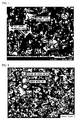
- FIG. 1 is a micrograph of the R-T-B-based magnet according to Experimental Example 3, which is an example of the R-T-B-based rare earth permanent magnet according to the present invention.
- a part colored with Oxford gray is a main phase
- a part colored with light gray is a grain boundary phase.
- the grain boundary phase included a first grain boundary phase (a part colored with verge on white within the part colored with light gray of FIG. 1 ) and a second grain boundary phase (a part colored with verge on black within the part colored with light gray of FIG. 1 ) which have different atomic concentration of Dy to each other.
- the backscattered electron image was photographed with 2,000 times magnification at 15kV accelerating voltage.
- FIG. 2 is a micrograph of the R-T-B-based magnet according to Experimental Example 1, which is an example of the R-T-B-based rare earth permanent magnet according to the present invention.
- a part colored with Oxford gray is a main phase.
- a boride of W (a part colored with verge on black within the part colored with light gray of FIG. 2 ) was deposited around W (a part colored with verge on white within the part colored with light gray of FIG. 2 ), which is a metal powder.
- the backscattered electron image was photographed with 1,000 times magnification at 15kV accelerating voltage.
- An R-T-B-based rare earth permanent magnet of the present invention includes a sintered body which is provided with a main phase mainly containing R 2 Fe 14 B, and with a grain boundary phase which has a greater R content than said main phase, wherein R denotes a rare earth element including Nd and Dy as an essential element, and the grain boundary phase includes a first grain boundary phase and a second grain boundary phase which have different atomic concentration of Dy to each other.
- the R-T-B-based rare earth permanent magnet of the present invention can possess a grain boundary phase having high effects of improving magnetic properties, as compared to a grain boundary phase of an R-T-B-based rare earth permanent magnet containing a single grain boundary phase having the same concentration of Dy in the R-T-B-based rare earth permanent magnet. Accordingly, it is possible to obtain a sufficiently high level of coercivity (Hcj) without increasing the Dy concentration, as compared to an R-T-B-based rare earth permanent magnet containing a single grain boundary phase having the same Dy concentration. Furthermore, it is possible to suppress the decrease of magnetic properties such as remanence (Br) due to the addition of Dy.
- R-T-B-based rare earth permanent magnet having excellent magnetic properties, which is suitably used for a motor, an automobile, a power generator, a wind power-generating apparatus, or the like. Therefore, the R-T-B-based rare earth permanent magnet of the present invention is extremely useful industrially.
Landscapes
- Chemical & Material Sciences (AREA)
- Engineering & Computer Science (AREA)
- Power Engineering (AREA)
- Materials Engineering (AREA)
- Mechanical Engineering (AREA)
- Metallurgy (AREA)
- Organic Chemistry (AREA)
- Crystallography & Structural Chemistry (AREA)
- Inorganic Chemistry (AREA)
- Hard Magnetic Materials (AREA)
- Powder Metallurgy (AREA)
Abstract
The present invention provides an R-T-B-based rare earth permanent magnet obtaining a high level of coercivity (Hcj) without increasing the Dy concentration in an R-T-B-based alloy, in addition, suppressing the decrease of remanence (Br) due to the addition of Dy, and obtaining excellent magnetic properties.
The present invention relates to an R-T-B-based rare earth permanent magnet including a sintered body which is provided with a main phase mainly containing R2Fe14B, and with a grain boundary phase which has a greater R content than said main phase, wherein R denotes a rare earth element including Nd and Dy as an essential element, and the grain boundary phase includes a first grain boundary phase and a second grain boundary phase which have different atomic concentration of Dy to each other.
Description
- The present invention relates to an R-T-B-based rare earth permanent magnet, a motor, an automobile, a power generator, and a wind power-generating apparatus, in particular, to an R-T-B-based rare earth permanent magnet that has a superior magnetic characteristic and is suitably used for a motor or a power generator, and to a motor, an automobile, a power generator, and a wind power-generating apparatus that use this R-T-B-based rare earth permanent magnet.
Priority is claimed on Japanese Patent Application No.2010-147580, filed June 29, 2010 , the content of which is incorporated herein by reference. - Conventionally, R-T-B-based rare earth permanent magnets are used in various types of motors, power generators or the like. In recent years, since demand for improving the heat tolerance of R-T-B-based rare earth permanent magnets has increased and also demand for energy conservation thereof has increased, the proportion of motor applications including applications in automobiles has increased.
An R-T-B-based rare earth permanent magnet contains Nd, Fe, and B serving as its primary component. R in an R-T-B-based magnet alloy is where a part ofNd has been substituted with another rare earth element such as Pr, Dy, and Tb. T is where a part of Fe has been substituted with another transition metal such as Co and Ni. B denotes boron. - As a material to be used for an R-Fe-B-based rare earth permanent magnet, there has been proposed one where in an R-Fe-B-based magnet alloy in which the presence volume ratio of R2Fe14B phase (where R denotes at least one type of a rare earth element), which is the primary phase component thereof, is 87.5 to 97.5% and the presence volume ratio of an oxide of a rare earth or a rare earth and a transitional metal is 0.1 to 3%, a compound with an average particle diameter of 5 µm or less, which is selected as a primary component in the metallic structure of the alloy from a ZrB compound composed ofZr and B, an NbB compound composed of Nb and B, and an HfB compound composed of Hf and B, disperses uniformly at maximum intervals of 50 µm or less in the adjacent compounds present in the alloy selected from the ZrB compound, the NbB compound, and the HfB compound (for example, refer to Patent Document 1).
- Moreover, as a material to be used for an R-Fe-B-based rare earth permanent magnet, there has also been proposed one where in an R-Fe-Co-B-Al-Cu (where R denotes one or more types among Nd, Pr, Dy, Tb, and Ho, containing 15 to 33 % by mass of Nd)-based rare earth permanent magnet material, at least two types from M-B-Cu-based compounds and M-C-based compounds (M denotes one or more types among Ti, Zr, and Hf) and, further, an R oxide are deposited in the alloy structure thereof (for example, refer to Patent Document 2).
-
- [Patent Document 1] Japanese Patent Publication No.
3951099 - [Patent Document 2] Japanese Patent Publication No.
3891307 - However, in recent years, there has been a demand for R-T-B-based rare earth permanent magnets of even higher performance, and a further improvement is required in the magnetic properties such as coercivity of R-T-B-based rare earth permanent magnets. Particularly in a motor, there is a problem such that a current is generated inside the motor during rotation and the motor per se reaches a high temperature as a result of heat generation, and thus a magnetic force decreases leading to a decrease in efficiency. In order to overcome this problem, a rare earth permanent magnet having a high coercivity at room temperature is required.
- As a method of enhancing the coercivity of the R-T-B-based rare earth permanent magnet, a method of increasing the Dy concentration in an R-T-B-based alloy is considered. As the Dy concentration in the R-T-B-based alloy is increased, a rare earth permanent magnet having a high coercivity (Hcj) can be obtained after sintering. However, when the Dy concentration in the R-T-B-based alloy is increased, remanence (Br) decreases.
Therefore, it was difficult to sufficiently enhance magnetic properties such as a coercivity of the R-T-B type rare earth permanent magnet in the prior art. - The present invention takes into consideration the above circumstances with an object of providing an R-T-B-based rare earth permanent magnet in which a high level of coercivity (Hcj) and excellent magnetic properties can be obtained without increasing the Dy concentration in the R-T-B-based alloy.
Moreover, an object of the present invention is to also provide a motor, an automobile, a power generator, and a wind power-generating apparatus that uses the above R-T-B-based rare earth permanent magnet having excellent magnetic properties. - The present inventors investigated the relationship between the Dy concentration of the grain boundary phase contained in an R-T-B-based rare earth permanent magnet, and the magnetic properties of the R-T-B-based rare earth permanent magnet. The present inventors have discovered that a sufficiently high level of coercivity (Hcj) can be obtained without increasing the Dy concentration by an R-T-B-based rare earth permanent magnet in which a grain boundary phase includes a first grain boundary phase and a second grain boundary phase wherein the Dy concentration of first grain boundary phase is different from that of the second grain boundary phase, as compared to an R-T-B-based rare earth permanent magnet containing a single grain boundary phase having the same Dy concentration.
- It is presumed that the following contribute to these effects. That is, when a grain boundary phase includes two types of grain boundary phase having a different Dy concentration to each other, a grain boundary phase having a high concentration of Dy exhibits strong resistance to a reverse of magnetic domain. As a result, a coercive force thereof is improved. Further, inside of a main phase being in contact with the grain boundary phase having the high Dy concentration, Dy is concentrated near a phase boundary of the main phase to the grain boundary phase. Accordingly, since strong resistance to a reverse of magnetic domain is exhibited, a coercive force thereof is improved.
- That is to say, the present invention is to provide each of the following aspects of the invention.
- (1) An R-T-B-based rare earth permanent magnet including a sintered body which is provided with a main phase mainly containing R2Fe14B, and with a grain boundary phase which has a greater R content than said main phase, wherein R denotes a rare earth element including Nd and Dy as an essential element, and the grain boundary phase includes a first grain boundary phase and a second grain boundary phase which have different atomic concentration of Dy to each other.
-
- (2) The R-T-B-based rare earth permanent magnet according to (1), wherein the Dy atomic concentration of the first grain boundary phase is less than that of the main phase, and the Dy atomic concentration of the second grain boundary phase is more than that of the main phase.
- (3) The R-T-B-based rare earth permanent magnet according to (2), wherein the Dy atomic concentration of the second grain boundary phase is 1.5 to 3 times that of the main phase.
-
- (4) The R-T-B-based rare earth permanent magnet according to (2) or (3), wherein the Dy atomic concentration of the second grain boundary phase is two to six times that of the first grain boundary phase.
- (5) The R-T-B-based rare earth permanent magnet according to any one of (2) to (4), wherein the second grain boundary phase has the Dy atomic concentration of 2 to 9 at%.
-
- (6) The R-T-B-based rare earth permanent magnet according to any one of (2) to (5), wherein the combined total of atomic concentration of rare earth elements contained in the second grain boundary phase is less than that in the first grain boundary phase.
- (7) The R-T-B-based rare earth permanent magnet according to any one of (2) to (6), wherein the combined total of atomic concentration of rare earth elements contained in the second grain boundary phase is 30 to 40 at%.
-
- (8) The R-T-B-based rare earth permanent magnet according to any one of (2) to (7), wherein an oxygen atomic concentration of the second grain boundary phase is higher than that of the main phase or that of the first grain boundary phase.
- (9) The R-T-B-based rare earth permanent magnet according to any one of (2) to (8), wherein the oxygen atomic concentration of the second grain boundary phase is 1.3 to 1.5 times the combined total of atomic concentration of rare earth element.
-
- (10) A motor provided with the R-T-B-based rare earth permanent magnet according to any one of (1) to (9).
- (11) An automobile provided with the motor according to (10).
- (12) A power generator provided with the R-T-B-based rare earth permanent magnet according to any one of (1) to (9).
- (13) A wind power-generating apparatus provided with the power generator according to (12).
- An R-T-B-based rare earth permanent magnet of the present invention includes a sintered body which is provided with a main phase mainly containing R2Fe14B, and with a grain boundary phase which has a greater R content than said main phase, wherein R denotes a rare earth element including Nd and Dy as an essential element, and the grain boundary phase includes a first grain boundary phase and a second grain boundary phase which have different atomic concentration of Dy to each other. Therefore, the R-T-B-based rare earth permanent magnet of the present invention can possess the grain boundary phase having high effects of improving magnetic properties, as compared to a grain boundary phase of an R-T-B-based rare earth permanent magnet containing a single grain boundary phase having the same concentration of Dy in the R-T-B-based rare earth permanent magnet.
- Accordingly, it is possible to obtain a sufficiently high level of coercivity (Hcj) without increasing the Dy concentration, as compared to an R-T-B-based rare earth permanent magnet containing a single grain boundary phase having the same Dy concentration. Furthermore, it is possible to suppress the deterioration of magnetic properties such as remanence (Br) due to the addition of Dy. Thus, it is possible to realize an R-T-B-based rare earth permanent magnet having excellent magnetic properties, which is suitably used for a motor, an automobile, a power generator, a wind power-generating apparatus, or the like.
-
-
FIG. 1 is a micrograph of an example of an R-T-B-based rare earth permanent magnet according to the present invention, and is also a micrograph of an R-T-B-based rare earth permanent magnet of Experimental Example 3. -
FIG. 2 is a micrograph of a micrograph of an R-T-B-based rare earth permanent magnet of Experimental Example 1, which is an example of an R-T-B-based rare earth permanent magnet according to the present invention. - Hereunder, an embodiment of the present invention is described in detail.
In an R-T-B-based rare earth permanent magnet (hereunder, abbreviated and referred to as "R-T-B-based magnet") of the present invention, R denotes a rare earth element including Nd and Dy as an essential element, T denotes a metal which essentially has Fe, and B denotes boron.
The R-T-B-based magnet of the present invention includes a sintered body which is provided with a main phase mainly containing R2Fe14B, and with a grain boundary phase which has a greater R content than said main phase. R denotes a rare earth element including Nd and Dy as an essential element. - The grain boundary phase constituting the R-T-B-based magnet of the present invention includes a first grain boundary phase and a second grain boundary phase which have different atomic concentration of Dy to each other.
In the present embodiment, a description will be given about the Dy atomic concentration of the second grain boundary phase being more than that of the first grain boundary phase. - In the R-T-B-based magnet of the present embodiment, it is preferable that the Dy atomic concentration of the first grain boundary phase be less than that of the main phase, and the Dy atomic concentration of the second grain boundary phase be more than that of the main phase. That is, the order of the Dy atomic concentration is expressed as follows: the first grain boundary phase < the main phase < the second grain boundary phase.
Generally, in an R-T-B-based magnet containing a single grain boundary phase having the same atomic concentration of Dy, the Dy concentration within the grain boundary phase is less than that of the main phase (the grain boundary phase < the main phase). Further, the Dy concentration within the grain boundary phase is defined, depending on the Dy concentration within the magnet. Furthermore, the higher the Dy concentration within the grain boundary phase is, the higher the effects of improving coercivity (Hcj) of the R-T-B-based magnet. - Conversely, in the R-T-B-based magnet of the present embodiment, the Dy atomic concentration of the second grain boundary phase contained in the grain boundary phase is more than that of the main phase. That is, in the present embodiment, the grain boundary phase is configured to contain the second grain boundary phase having a high atomic concentration of Dy to have high effects of improving coercivity (Hcj) of the R-T-B-based magnet, as compared to a grain boundary phase of an R-T-B-based magnet containing a single grain boundary phase having the same concentration of Dy in the R-T-B-based magnet. In this manner, even when the Dy concentration within the magnet is low, the R-T-B-based magnet of the present embodiment can obtain a sufficiently high level of coercivity (Hcj).
- Further, the Dy atomic concentration of the second grain boundary phase is preferably 1.5 to 3 times that of the main phase. Furthermore, the Dy atomic concentration of the second grain boundary phase is preferably 2 to 6 times that of the first grain boundary phase.
Either when the Dy atomic concentration of the second grain boundary phase in comparison with that of the main phase is within the above-mentioned range, or when the Dy atomic concentration of the second grain boundary phase in comparison with that of the first grain boundary phase is within the above-mentioned range, the second grain boundary phase exhibits very excellent effects of improving coercivity (Hcj) of the R-T-B-based magnet. Therefore, an enhanced-high level of coercivity (Hcj) can be obtained. - Further, the second grain boundary phase preferably has the Dy atomic concentration of 2 to 9 at%. When the Dy atomic concentration of the second grain boundary phase is within the above-mentioned range, the second grain boundary phase exhibits very excellent effects of improving coercivity (Hcj) of the R-T-B-based magnet. Therefore, an enhanced-high level of coercivity (Hcj) can be obtained. When the Dy atomic concentration of the second grain boundary phase is less than the above-mentioned range, there is a concern that effects of improving coercivity of the R-T-B-based magnet due to the second grain boundary phase can not be sufficiently obtained. On the other hand, when the Dy atomic concentration of the second grain boundary phase is more than the above-mentioned range, remanence (Br) is reduced. As a result, there is a concern that remanence (Br) become inadequate.
- Further, an oxygen atomic concentration of the second grain boundary phase is preferably higher than that of the main phase or that of the first grain boundary phase. It is presumed as follows. Rare earth elements contained in the second grain boundary phase are present in the state of an oxide thereof such as R2O3 within the second grain boundary phase. The second grain boundary phase is formed by oxidizing the rare earth elements. Since Dy is readily oxidized as compared to Nd, the atomic concentration of Dy is increased. As a result, the atomic concentration of Dy contained in the second grain boundary phase becomes sufficiently higher than that of the main phase or that of the first grain boundary phase. Therefore, the second grain boundary phase has very high effects of improving coercivity (Hcj) of the R-T-B-based magnet to obtain an enhanced-high level of coercivity (Hcj).
- The oxygen atomic concentration of the second grain boundary phase may specifically be 1 to 1.5 times the combined total of atomic concentration of rare earth elements, and preferably 1.3 to 1.5 times. Further, the oxygen atomic concentration of the second grain boundary phase is preferably 40 to 50 at%. Either when the oxygen atomic concentration of the second grain boundary phase is 1 to 1.5 times the combined total of atomic concentration of rare earth elements, or when the oxygen atomic concentration of the second grain boundary phase is 40 to 50 at%, the atomic concentration of Dy contained in the second grain boundary phase can be sufficiently ensured. As a result, the second grain boundary phase has very high effects of improving coercivity (Hcj) of the R-T-B-based magnet. Therefore, it is presumed that an enhanced-high level of coercivity (Hcj) can be obtained.
- When the oxygen atomic concentration of the second grain boundary phase based on the combined total of atomic concentration of rare earth elements is less than the above-mentioned range, the atomic concentration of Dy contained in the second grain boundary phase is difficult to be enhanced. Therefore, there is a concern that the atomic concentration of Dy contained in the second grain boundary phase becomes inadequate. On the other hand, when the oxygen atomic concentration of the second grain boundary phase based on the combined total of atomic concentration of rare earth elements is more than the above-mentioned range, the elements such as Fe other than rare earth elements are oxidized to reduce coercivity (Hcj).
- Further, a preferable composition of the R-T-B-based magnet of the present invention is one where R is contained at 27 to 33 % by mass or more preferably 30 to 32 % by mass, B is contained at 0.85 to 1.3 % by mass or more preferably 0.87 to 0.98 % by mass, and the remnant is T and unavoidable impurities.
- The level of coercivity may become insufficient in some cases if R constituting the R-T-B-based magnet is less than 27 % by mass, and remanence may become insufficient in some cases if R exceeds 33 % by mass.
In addition, R of the R-T-B-based magnet preferably contains Nd serving as the primary component thereof. An example of rare earth elements contained in R of the R-T-B-based magnet other than Nd and Dy includes Sc, Y, La, Ce, Pr, Pm, Sm, Eu, Gd, Tb, Ho, Er, Tm, Yb and Lu. Of these, Pr and Tb are particularly desirable. - The Dy atomic concentration within the R-T-B-based magnet is preferably 2 to 17 % by mass, more preferably 2 to 15 % by mass and still more preferably 4 to 10 % by mass. When the Dy atomic concentration within the R-T-B-based magnet exceeds 17 % by mass, remanence (Br) is remarkably reduced. On the other hand, when the Dy atomic concentration within the R-T-B-based magnet is less than 2 % by mass, coercivity of the R-T-B-based magnet may be insufficient for motor applications.
- T contained in the R-T-B-based magnet denotes a metal that essentially contains Fe, and other than Fe, it may contain a transition metal such as Co and Ni. If Co is contained other than Fe, it is preferable because the Tc (Curie temperature) can be improved.
- Further, B contained in the R-T-B-based magnet is preferably 0.85 to 1.3 % by mass. When B constituting the R-T-B-based magnet is less than 0.85 % by mass, coercivity of the R-T-B-based magnet may be insufficient. On the other hand, when B is more than 1.3 % by mass, remanence (Br) may be remarkably reduced.
B contained in the R-T-B-based magnet denotes boron, however, a part thereof may be substituted either with C or N. - Further, in order to improve the coercivity, the R-T-B-based magnet preferably contains Al, Cu, and Ga.
Ga is to be contained preferably at 0.03 % by mass to 0.3 % by mass. If Ga is contained at 0.03 % by mass or more, the coercivity can be effectively improved. However, it is not preferable if the Ga content exceeds 0.3 % by mass, because remanence is reduced.
Al is to be contained preferably at 0.01 % by mass to 0.5 % by mass. If Al is contained at 0.01 % by mass or more, the coercivity can be effectively improved. However, it is not preferable if the Al content exceeds 0.5 % by mass, because remanence is reduced. - Furthermore, the oxygen concentration of the R-T-B-based magnet is preferably as low as possible. The oxygen concentration is preferably 0.5 % by mass or less, and more preferably 0.2 % by mass or less. When the oxygen content is 0.5 % by mass or less, a sufficient level of magnetic characteristic for an application to a motor can be achieved. When the oxygen content exceeds 0.5 % by mass, there is a possibility that the magnetic characteristic may be significantly reduced.
Moreover, the carbon concentration of the R-T-B-based magnet is preferably as low as possible. The carbon concentration is preferably 0.5 % by mass or less, and more preferably 0.2 % by mass or less. When the carbon content is 0.5 % by mass or less, a sufficient level of magnetic characteristic for an application to a motor can be achieved. If the carbon content exceeds 0.5 % by mass, then there will be a possibility that the magnetic characteristic may be significantly reduced. - Next, a method for manufacturing the R-T-B-based magnet of the present invention is described. Examples of the method for manufacturing the R-T-B-based magnet of the present invention include a method in which raw materials containing an alloy material for the permanent magnet are pressed, sintered, followed by heat-treated.
As the alloy material for the permanent magnet used in manufacturing the R-T-B-based magnet of the present invention, an alloy material having a composition corresponding to a composition of the R-T-B-based magnet, and including an R-T-B-based alloy and a metal powder is preferably used. When the alloy material including an R-T-B-based alloy and a metal powder is used as the alloy material for the permanent magnet, the alloy material is pressed and followed by sintered to readily obtain an R-T-B-based magnet in which a grain boundary phase includes a first grain boundary phase and a second grain boundary phase having different atomic concentration of Dy to each other. - Moreover, the alloy material for the permanent magnet is preferably a mixed material of a powder composed of an R-T-B-based alloy and a metal powder. When the alloy material for the permanent magnet is the mixed material of a powder composed of an R-T-B-based alloy and a metal powder, an alloy material for the permanent magnet having uniform quality can readily be obtained by only mixing a powder of an R-T-B-based alloy and a metal powder. In addition, by pressing the alloy material for the permanent magnet, followed by sintering, an R-T-B-based magnet having uniform quality can readily be obtained.
- It is preferable that R denote one member, or two or more members selected from rare earth elements within the R-T-B-based alloy contained in the alloy material for the permanent magnet, and Dy be contained at 2 to 17 % by mass in the R-T-B-based alloy.
The average grain size (d50) of the powder composed of the R-T-B-based alloy is preferably 3 to 4.5 µm. Further, the preferred average grain size (d50) of the metal powder is in a range of 0.01 to 300 µm. - Further, as the metal powder contained in the alloy material for the permanent magnet, a powder such as Al, Si, Ti, Ni, W, Zr, TiAl alloy, Cu, Mo, Co, Fe and Ta can be used. The metal powder is not particularly limited, but preferably contains a powder of any one of Al, Si, Ti, Ni, W, Zr, TiAl alloy, Co, Fe and Ta, and more preferably a powder of any one of Fe, Ta and W.
- The metal powder is preferably contained at 0.002 to 6 % by mass within the alloy material for the permanent magnet, more preferably at 0.01 to 4 % by mass, and still more preferably at 0.5 to 2 % by mass. When the content of the metal powder is less than 0.002 % by mass, the grain boundary phase of the R-T-B-based magnet is not configured to include a first grain boundary phase and a second grain boundary phase having different atomic concentration of Dy to each other. As a result, coercivity (Hcj) of the R-T-B-based magnet may not be sufficiently improved. On the other hand, it is not preferable if the content of the metal powder exceeds 6 % by mass, because the magnetic properties of the R-T-B-based magnet such as remanence (Br) and maximum energy product (BHmax) are significantly reduced.
- The alloy material for the permanent magnet used in manufacturing the R-T-B-based magnet of the present invention may be produced by mixing an R-T-B-based alloy and a metal powder, although it is preferable to be produced by mixing a powder composed of an R-T-B-based alloy and a metal powder.
The powder composed of the R-T-B-based alloy may be obtained, for example, by a method in which a molten alloy melt is cast by means of an SC (strip casting) method to manufacture a cast alloy thin strip, the obtained cast alloy thin strip is then crushed, for example, by means of a hydrogen decrepitation method, and it is then pulverized using a pulverizer. - Examples of the hydrogen decrepitation method include a method in which after having absorbed hydrogen in a cast alloy thin strip at room temperature and heat-treated it at a temperature of approximately 300 °C, hydrogen is degassed by depressurization, and then it is heat-treated at a temperature of approximately 500°C to thereby remove the hydrogen in the cast alloy thin strip. In the hydrogen decrepitation method, the cast alloy thin strip having absorbed hydrogen expands in volume, and consequently a number of cracks are generated in the cast alloy therein and the cast iron strip is thereby crushed.
Moreover, examples of the method of pulverizing the hydrogen decrepitated cast alloy thin strip include a method in which on a pulverizer such as a jet mill, the hydrogen decrepitated cast alloy thin strip is fine-pulverized to an average grain size of 3 to 4.5 µm using highly pressurized nitrogen at 0.6 MPa, to thereby prepare it in a powder form. - Examples of a method of manufacturing an R-T-B-based magnet with use of an alloy material for the permanent magnet obtained in this way include a method in which raw material, in which 0.02 to 0.003 % by mass of zinc stearate is added as a lubricating agent to the alloy material for the permanent magnet, is pressed using a pressing machine while applying a transverse magnetic field and is sintered in a vacuum at 1,030 to 1,080 °C, and is then heat-treated at 400 to 800 °C.
- A case of manufacturing an R-T-B-based alloy using an SC method was described in the examples above, however, the R-T-B-based alloy used in the present invention is not to be considered limited to one that is manufactured using an SC method. For example, an R-T-B-based alloy may also be cast by means of a centrifugal casting method, a book pressing method, and the like.
- Moreover, the R-T-B-based alloy and the metal powder, as described above, may be mixed after having cracked a cast alloy thin strip and prepared it as a powder composed of the R-T-B-based alloy. However, for example, the cast alloy thin strip and the metal powder may be mixed to thereby prepare it as an alloy material for the permanent magnet before cracking the cast alloy thin strip, and then the alloy material for the permanent magnet that contains the cast alloy thin strip may be cracked. In this case, it is preferable that the alloy material for the permanent magnet composed of the cast alloy thin strip and the metal powder be cracked in a manner similar to the method of cracking the cast alloy thin strip, and then it be pressed and sintered in a manner similar to that described above, to thereby manufacture an R-T-B-based magnet.
Moreover, mixing of the R-T-B-based alloy and the metal powder may be conducted after having added a lubricating agent such as zinc stearate to the powder composed of the R-T-B-based alloy. - The metal powder in the alloy material for the permanent magnet of the present invention may be finely and uniformly distributed. However, it may not need to be finely and uniformly distributed, and for example, the grain size thereof may be 1 µm or greater, or it may be aggregated in a size of 5 µm or greater for achieving the effect. Further, the higher the Dy concentration is, the higher the effects of improving coercivity due to a metal powder being contained in an alloy material for the permanent magnet. Furthermore, if Ga is contained therein, the effects are significantly exhibited.
- The R-T-B-based magnet of the present embodiment is configured so that the grain boundary phase includes a first grain boundary phase and a second grain boundary phase which have different atomic concentration of Dy to each other, the Dy atomic concentration of the first grain boundary phase being less than that of the main phase, and the Dy atomic concentration of the second grain boundary phase being more than that of the main phase. Therefore, the R-T-B-based magnet of the present embodiment has a high level of coercivity (Hcj) and also becomes suitable as a magnet for a motor having a sufficiently high level of remanence (Br).
- It is preferable that the coercivity (Hcj) of the R-T-B-based magnet be as high as possible, although it is preferably 30 kOe or more in those cases where it is used as a magnet for a motor. If the coercivity (Hcj) in a magnet for a motor is less than 30 kOe, the heat tolerance thereof for a motor may become insufficient in some cases.
Further, it is also preferable that the remanence (Br) of the R-T-B-based magnet be as high as possible, although it is preferably 10.5kG or more in those cases where it is used as a magnet for a motor. It is not preferable for a magnet in a motor if the remanence (Br) of the R-T-B-based magnet is less than 10.5kG, because the torque of the motor may be insufficient. - In the R-T-B-based magnet of the present embodiment, it is possible to obtain a sufficiently high level of coercivity (Hcj) without increasing the Dy concentration within the R-T-B-based alloy. Hence, the R-T-B-based magnet of the present embodiment has excellent magnetic properties to be suitably used for a motor, an automobile, a power generator, a wind power-generating apparatus, or the like.
- An Nd metal (purity 99 wt% or greater), Pr metal (purity 99 wt% or greater), Dy metal (purity 99 wt% or greater), ferroboron (Fe 80wt%, B 20wt%), Al metal (purity 99 wt% or greater), Co metal (purity 99 wt% or greater), Cu metal (purity 99 wt% or greater), Ga metal (purity 99 wt% or greater), and iron mass (purity 99 wt% or greater) were weighed so as to correspond to the component composition of an alloy A shown in Table 1, and were charged into an alumina crucible.
-
[Table 1] Thickness (mm) Component (wt%) Average grain size d50 (µm) Nd Pr Dy B Al Co Cu Ga C O Fe Alloy A 0.29 17.0 6.0 9.5 0.9 0.1 1.0 0.1 0.08 0.012 0.013 Balance 4.5 Alloy B 0.30 20.0 6.0 4.5 0.9 0.1 1.0 0.1 0.08 0.012 0.013 Balance 4.5 Alloy C 0.30 24.5 6.0 0.0 0.9 0.1 1.0 0.1 0.08 0.012 0.013 Balance 4.5 - Then, the inside of the furnace of a high frequency vacuum induction furnace where the alumina crucible was placed was substituted with Ar. Having heated to 1,450 °C to melt, the melt thereof was poured on a water-cooled copper roll, and an SC (strip casting) method was performed at a peripheral speed of 1.0 m/second so as to have an average thickness of approximately 0.3 mm, a distance between R-rich phases of 3 to 15 µm, and a volume ratio of a phase (the main phase) other than the R-rich phases ≥ (138-1.6r) (wherein r is the content of rare earths (Nd, Pr, Dy)), to thereby obtain a cast alloy thin strip.
- The distance between R-rich phases and the volume ratio of the main phase of the cast alloy thin strip thus obtained were examined by the following methods. That is, the cast alloy thin strip having a thickness within an average thickness ± 10% was embedded in a resin and, after polishing, a backscattered electron image was photographed by a scanning electron microscope (JEOL JSM-5310). Using the obtained 300 times magnification micrograph, the distance between R-rich phases was measured and also the volume ratio of the main phase was calculated. As a result, the distance between R-rich phases of an alloy A shown in Table 1 was from 4 to 5 µm, and the volume ratio of the main phase was from 90 to 95%.
- Next, the cast alloy thin strip was then crushed by means of a hydrogen decrepitation method described below. First, the cast alloy thin strip was coarse-crushed so that the diameter thereof became approximately 5 mm, and it was then inserted into a hydrogen atmosphere at room temperature to thereby have hydrogen absorbed therein. Subsequently, heat treatment was performed in which the cast alloy thin strip that had been coarse-crushed and had occluded hydrogen therein was heated to 300 °C. Then, cracking was performed by a method in which hydrogen was degassed by depressurization, heat treatment was performed to further heat it to 500°C to thereby have hydrogen in the cast alloy thin strip released and removed, and then it was cooled to room temperature.
Next, 0.025wt% of zinc stearate was added as a lubricating agent to the cracked cast alloy thin strip, and on a jet mill (Hosokawa Micron 100AFG), the hydrocracked cast alloy thin strip was fine-pulverized into powder at an average grain size of 4.5 µm, using highly pressurized nitrogen at 0.6 MPa. - A metal powder having the average grain size shown in Table 2 was added to and mixed with the powder (alloy A) composed of the R-T-B-based alloy having the average grain size shown in Table 1 obtained in this way, according to the proportion (concentration (% by mass) of the metal powder contained in the alloy material for the permanent magnet) shown in Table 3, to thereby manufacture the alloy material for the permanent magnet. The grain size of the metal powder was measured using a laser diffraction meter.
-
[Table 2] Metal powder Average grain Size d50 ( µm) W 6.5 Ta 11.5 Fe 6.2 -
[Table 3] Experimental Example Alloy Metal powder Additive amount (wt%) Hcj (kOe) Br (kG) SR (%) Bhmax (MGOe) 1 A W 1.0 35.4 11.4 89.9 31.9 2 A Ta 1.0 34.0 11.5 90.7 32.7 3 A Fe 2.0 34.1 11.7 90.7 33,8 4 A None 0.0 29.8 11.7 90.8 33.2 5 B W 0.6 23.6 13.0 94.5 41.1 6 B Ta 1.8 24.0 12.8 94.4 39.7 7 B Fe 1.0 23.1 13.0 95.1 41.1 8 B None 0.0 22.5 13.1 94.7 41.5 9 C W 2.0 14.0 13.3 91.9 41.3 10 C Ta 1.0 15.0 13.7 95.4 45.3 11 C Fe 4.0 11.2 13.8 93.2 43.7 12 C None 0.0 14.6 14.2 95.6 48.3 - Next, the alloy material for the permanent magnet obtained in this way was pressed at a pressing pressure 0.8 t/cm2, using a pressing machine applying transverse magnetic field, to thereby prepare a powder compact. Then, the obtained powder compact was sintered in a vacuum. The powder compact was sintered at a temperature of 1, 080 °C. Then, the powder compact was heat-treated at 500 °C, and was then cooled, to thereby manufacture the R-T-B-based magnets of Experimental Example 1 to Experimental Example 4.
- By using a BH curve tracer (Toei Kogyo TPM2-10), the magnetic properties of the respective R-T-B-based magnets of Experimental Example 1 to Experimental Example 4 that were obtained with use of the alloy material for the permanent magnet containing a metal powder and the alloy material for the permanent magnet not containing the metal powder were measured. The results of this are shown in Table 3.
In Table 3, "Hcj" represents coercivity, "Br" represents remanence, "SR" represents squareness, and "BHmax" represents maximum energy product. Moreover, these values of magnetic properties are the average values of the measured values of the respective five R-T-B-based magnets. - Further, a backscattered electron image of the R-T-B-based magnet according to Experimental Examples 1 to 4 was projected using FE-EPMA (Electron Probe Micro Analyzer). The main phase and the grain boundary phase of R-T-B-based magnet were discriminated based on the contrast of the backscattered electron image. Thereafter, the composition of the main phase and the grain boundary phase was investigated with a point analysis using WDX (wavelength dispersive X-ray spectrometry apparatus), thereby calculating the compositional ratio thereof. The results of this are shown in Table 4.
-
[Table 4] Compotion of each phase of alloy A sintered magnet Unit: at% Experimental Example Nd Pr Dy Combined total of R Fe B C O The others 1 W 1.0wt% Main phase 6.4 1.7 3.6 11.7 76.9 5.0 0.1 2.1 4.2 First grain boundary phase 37.4 16.1 1.6 55.1 15.6 0.0 7.3 5.6 16.4 Second grain boundary phase 20.1 5.8 8.2 34.1 5.4 0.0 16.2 44.3 0.0 2 Ta 1.0wt% Main phase 6.5 1.8 3.5 11.8 77.7 5.0 0.1 2.1 3.3 First grain boundary phase 34.5 14.8 2.1 51.4 27.1 0.0 4.8 5.0 11.7 Second grain boundary phase 19.9 5.8 8.1 33.8 7.5 0.0 14.4 44.3 0.0 3 Fe 2.0wt% Main phase 6.4 1.7 3.5 11.6 76.9 4.8 0.8 3.4 2.5 First grain boundary phase 36.1 16.5 1.4 54.0 17.3 0.0 4.1 8. 3 16.3 Second grain boundary phase 20.3 6.2 7.1 33.6 33.6 0.0 14.6 48.8 0.0 4 No additives Main phase 6.5 1.8 3.5 11.8 77.4 4.7 0.3 3.3 2.5 First grain boundary phase 40.3 17.6 1.0 58.9 12.7 0.0 4.4 6.6 17.4 - Each component was weighed so as to correspond to the component composition of an alloy B or C shown in Table 1, thereby manufacturing the powder (the alloy B or C) composed of the R-T-B-based alloy having an average grain size shown in Table 1 in the same procedure as Experimental Examples 1 to 4. Next, the metal powders having the grain size shown in Table 2 were added to the alloy B or C at the proportion shown in Table 3, and they were mixed, thereby manufacturing the alloy material for the permanent magnets. These alloy materials for the permanent magnet were pressed, sintered in the same procedure as Experimental Examples 1 to 4, to thereby manufacture the R-T-B-based magnets of Experimental Examples 5 to 12. Thereafter, magnetic properties and a compositional ratio of each phase were measured in the same manner as Experimental Examples 1 to 4.
- The results of this are shown in Tables 5 and 6. Since the alloy C contained no Dy, R-T-B-based magnets manufactured from the alloy C may not contain a second grain boundary phase. However, in the Experimental Examples 9 to 11, a phase having a composition different from that of the first grain boundary phase was observed. Hence, for the sake of simplicity, the phase was described in Table 6 as a second grain boundary phase.
-
[Table 5] Composition of each phase of alloy B sintered magnet Unit at% Experimental Example Nd Pr Dy Combined total of R Fe B C O The others 5 W 0.6wt% Main phase 8.0 2.2 1.7 11.9 77.9 4.7 0.7 2.2 2.6 First grain boundary phase 41.9 20.1 0.6 62.6 19.6 0.0 4.8 6.8 6.2 Second grain boundary phase 23.1 7.2 2.8 33.1 3.7 0.0 13.3 49.9 0.0 6 Ta 1.8wt% Main phase 8.6 2.6 1.7 12.8 77.4 4.7 0.2 2.1 2.8 First grain boundary phase 40.9 17.6 1.0 59.5 11.5 0.0 3.9 11.1 14.0 Second grain boundary phase 23.6 7.3 2.8 33.7 3.3 0.0 13.7 49.1 0.2 7 Fe 1.0wt% Main phase 8.0 2.2 1.7 11.9 78.6 4.7 0.2 1.9 2.7 First grain boundary phase 41.4 20.3 0.5 62.2 20.9 0.0 4.6 9.8 2.5 Second grain boundary phase 24.3 7.4 3.0 34.7 3.1 0.0 15.1 47.1 0.0 8 No additives Main phase 8.0 2.2 1.7 11.9 77.5 4.8 0.4 2.8 2.6 First grain boundary phase 41.9 21.0 0.3 63.3 8.8 0.0 8.1 19.3 0.5 -
[Table 6] Composition of each phase of alloy C sintered magnet Unit at% Experimental Example Nd Pr Dy Combined total of R Fe B C O The others 9 W 2.0wt% Main phase 9.4 2.5 0.0 11.9 77.5 4.7 0.7 2.6 2.6 First grain boundary phase 40.7 17.8 0.0 58.5 15.0 0.0 3.8 5.9 16.8 Second grain boundary phase 26.8 8.2 0.0 35.0 3.1 0.0 12.9 49.0 0.0 10 Ta 1.0wt% Main phase 9.5 2.6 0.0 12.1 78.7 4.9 0.3 1.3 2.7 First grain boundary phase 37.9 17.4 0.0 55.3 16.2 0.0 5.0 7.4 16.1 Second grain boundary phase 29.2 8.8 0.0 38.0 2.7 0.0 18.1 41.2 0.0 11 Fe 4.0wt% Main phase 9.3 2.5 0.0 11.8 78.2 5.4 0.2 1.8 2.6 First grain boundary phase 34.5 15.8 0.0 50.1 23.2 0.0 3.5 9.3 13.9 Second grain boundary phase 24.8 8.1 0.0 32.9 3.7 0.0 14.0 49.4 0.0 12 No additives Main phase 9.2 2.5 0.0 11.7 77.3 4.8 0.4 3.1 2.7 First grain boundary phase 37.1 16.1 0.0 53.2 16.1 0.0 4.3 11.3 15.1 - As shown in Tables 3 to 5, R-T-B-based magnets according to Experimental Examples 1 to 3 and Experimental Examples 5 to 7 where the grain boundary phase included the first grain boundary phase and the second grain boundary phase having a different average atomic weight to each other has a high level of coercivity (Hcj) as compared to R-T-B-based magnets according to Experimental Examples 4 and 8 where the grain boundary phase is only a single phase. Accordingly, it was found that when the grain boundary phase includes the first grain boundary phase and the second grain boundary phase, coercivity can be enhanced without increasing the additive amount of Dy.
Further, since the alloy C does not contain Dy, R-T-B-based magnets of Experimental Examples 9 to 11 contain no second grain boundary phase. Therefore, as shown in Table 3, R-T-B-based magnets of Experimental Examples 9 to 11 do not exhibit enhanced coercivity as compared to R-T-B-based magnet of Experimental Example 12. -
FIG. 1 is a micrograph of the R-T-B-based magnet according to Experimental Example 3, which is an example of the R-T-B-based rare earth permanent magnet according to the present invention. In the micrograph (backscattered electron image of FE-EPMA) of the R-T-B-based magnet shown inFIG. 1 , a part colored with Oxford gray is a main phase, and a part colored with light gray is a grain boundary phase. In the R-T-B-based magnet shown inFIG. 1 , it was found that the grain boundary phase included a first grain boundary phase (a part colored with verge on white within the part colored with light gray ofFIG. 1 ) and a second grain boundary phase (a part colored with verge on black within the part colored with light gray ofFIG. 1 ) which have different atomic concentration of Dy to each other.
The backscattered electron image was photographed with 2,000 times magnification at 15kV accelerating voltage. -
FIG. 2 is a micrograph of the R-T-B-based magnet according to Experimental Example 1, which is an example of the R-T-B-based rare earth permanent magnet according to the present invention. In the micrograph (backscattered electron image of FE-EPMA) of the R-T-B-based magnet shown inFIG. 2 , a part colored with Oxford gray is a main phase. In the R-T-B-based magnet shown inFIG. 2 , it was found that a boride of W (a part colored with verge on black within the part colored with light gray ofFIG. 2 ) was deposited around W (a part colored with verge on white within the part colored with light gray ofFIG. 2 ), which is a metal powder.
The backscattered electron image was photographed with 1,000 times magnification at 15kV accelerating voltage. - An R-T-B-based rare earth permanent magnet of the present invention includes a sintered body which is provided with a main phase mainly containing R2Fe14B, and with a grain boundary phase which has a greater R content than said main phase, wherein R denotes a rare earth element including Nd and Dy as an essential element, and the grain boundary phase includes a first grain boundary phase and a second grain boundary phase which have different atomic concentration of Dy to each other. Therefore, the R-T-B-based rare earth permanent magnet of the present invention can possess a grain boundary phase having high effects of improving magnetic properties, as compared to a grain boundary phase of an R-T-B-based rare earth permanent magnet containing a single grain boundary phase having the same concentration of Dy in the R-T-B-based rare earth permanent magnet. Accordingly, it is possible to obtain a sufficiently high level of coercivity (Hcj) without increasing the Dy concentration, as compared to an R-T-B-based rare earth permanent magnet containing a single grain boundary phase having the same Dy concentration. Furthermore, it is possible to suppress the decrease of magnetic properties such as remanence (Br) due to the addition of Dy. Thus, it is possible to realize an R-T-B-based rare earth permanent magnet having excellent magnetic properties, which is suitably used for a motor, an automobile, a power generator, a wind power-generating apparatus, or the like. Therefore, the R-T-B-based rare earth permanent magnet of the present invention is extremely useful industrially.
Claims (13)
- An R-T-B-based rare earth permanent magnet comprising a sintered body which is provided with a main phase mainly containing R2Fe14B, and with a grain boundary phase which has a greater R content than said main phase, wherein
R denotes a rare earth element including Nd and Dy as an essential element, and
the grain boundary phase includes a first grain boundary phase and a second grain boundary phase which have different atomic concentration of Dy to each other. - The R-T-B-based rare earth permanent magnet according to Claim 1, wherein the Dy atomic concentration of the first grain boundary phase is less than that of the main phase, and
the Dy atomic concentration of the second grain boundary phase is more than that of the main phase. - The R-T-B-based rare earth permanent magnet according to Claim 2, wherein the Dy atomic concentration of the second grain boundary phase is 1.5 to 3 times that of the main phase.
- The R-T-B-based rare earth permanent magnet according to Claim 2 or 3, wherein the Dy atomic concentration of the second grain boundary phase is two to six times that of the first grain boundary phase.
- The R-T-B-based rare earth permanent magnet according to any one of Claims 2 to 4, wherein the second grain boundary phase has the Dy atomic concentration of 2 to 9 at%.
- The R-T-B-based rare earth permanent magnet according to any one of Claims 2 to 5, wherein the combined total of atomic concentration of rare earth elements contained in the second grain boundary phase is less than that in the first grain boundary phase.
- The R-T-B-based rare earth permanent magnet according to any one of Claims 2 to 6, wherein the combined total of atomic concentration of rare earth elements contained in the second grain boundary phase is 30 to 40 at%.
- The R-T-B-based rare earth permanent magnet according to any one of Claims 2 to 7, wherein an oxygen atomic concentration of the second grain boundary phase is higher than that of the main phase or that of the first grain boundary phase.
- The R-T-B-based rare earth permanent magnet according to any one of Claims 2 to 8, wherein the oxygen atomic concentration of the second grain boundary phase is 1.3 to 1.5 times the combined total of atomic concentration of rare earth element.
- A motor provided with the R-T-B-based rare earth permanent magnet according to any one of Claims 1 to 9.
- An automobile provided with the motor according to Claim 10.
- A power generator provided with the R-T-B-based rare earth permanent magnet according to any one of Claims 1 to 9.
- A wind power-generating apparatus provided with the power generator according to Claim 12.
Applications Claiming Priority (2)
| Application Number | Priority Date | Filing Date | Title |
|---|---|---|---|
| JP2010147580A JP2012015168A (en) | 2010-06-29 | 2010-06-29 | R-t-b-based rare earth permanent magnet, motor, vehicle, generator and wind power generator |
| PCT/JP2011/061537 WO2012002059A1 (en) | 2010-06-29 | 2011-05-19 | R-t-b type rare earth permanent magnet, motor, automobile, power generator, and wind power generation system |
Publications (1)
| Publication Number | Publication Date |
|---|---|
| EP2590180A1 true EP2590180A1 (en) | 2013-05-08 |
Family
ID=45401793
Family Applications (1)
| Application Number | Title | Priority Date | Filing Date |
|---|---|---|---|
| EP11800528.9A Withdrawn EP2590180A1 (en) | 2010-06-29 | 2011-05-19 | R-t-b type rare earth permanent magnet, motor, automobile, power generator, and wind power generation system |
Country Status (5)
| Country | Link |
|---|---|
| US (1) | US20130099150A1 (en) |
| EP (1) | EP2590180A1 (en) |
| JP (1) | JP2012015168A (en) |
| CN (1) | CN102959647B (en) |
| WO (1) | WO2012002059A1 (en) |
Cited By (1)
| Publication number | Priority date | Publication date | Assignee | Title |
|---|---|---|---|---|
| EP3291251A4 (en) * | 2015-04-30 | 2018-12-12 | IHI Corporation | Rare earth permanent magnet and method for producing rare earth permanent magnet |
Families Citing this family (20)
| Publication number | Priority date | Publication date | Assignee | Title |
|---|---|---|---|---|
| JP5767788B2 (en) * | 2010-06-29 | 2015-08-19 | 昭和電工株式会社 | R-T-B rare earth permanent magnet, motor, automobile, generator, wind power generator |
| JP5743458B2 (en) * | 2010-09-03 | 2015-07-01 | 昭和電工株式会社 | Alloy material for RTB-based rare earth permanent magnet, method for manufacturing RTB-based rare earth permanent magnet, and motor |
| CN104137197B (en) * | 2012-02-13 | 2015-08-19 | Tdk株式会社 | R-t-b based sintered magnet |
| WO2013122256A1 (en) | 2012-02-13 | 2013-08-22 | Tdk株式会社 | R-t-b sintered magnet |
| JP6221246B2 (en) * | 2012-10-31 | 2017-11-01 | 日立金属株式会社 | R-T-B system sintered magnet and manufacturing method thereof |
| JP6221233B2 (en) * | 2012-12-28 | 2017-11-01 | 日立金属株式会社 | R-T-B system sintered magnet and manufacturing method thereof |
| JP6303480B2 (en) | 2013-03-28 | 2018-04-04 | Tdk株式会社 | Rare earth magnets |
| JP6314380B2 (en) * | 2013-07-23 | 2018-04-25 | Tdk株式会社 | Rare earth magnet, electric motor, and device including electric motor |
| DE112014003688T5 (en) | 2013-08-09 | 2016-04-28 | Tdk Corporation | Sintered magnet based on R-T-B and motor |
| JP6330813B2 (en) | 2013-08-09 | 2018-05-30 | Tdk株式会社 | R-T-B system sintered magnet and motor |
| JP6142794B2 (en) | 2013-12-20 | 2017-06-07 | Tdk株式会社 | Rare earth magnets |
| JP6142793B2 (en) | 2013-12-20 | 2017-06-07 | Tdk株式会社 | Rare earth magnets |
| JP6142792B2 (en) | 2013-12-20 | 2017-06-07 | Tdk株式会社 | Rare earth magnets |
| JP6380750B2 (en) * | 2014-04-15 | 2018-08-29 | Tdk株式会社 | Permanent magnet and variable magnetic flux motor |
| JP2016017203A (en) * | 2014-07-08 | 2016-02-01 | 昭和電工株式会社 | Production method for r-t-b-based rear earth sintered magnetic alloy and production method for r-t-b-based rear earth sintered magnet |
| WO2018034264A1 (en) * | 2016-08-17 | 2018-02-22 | 日立金属株式会社 | R-t-b sintered magnet |
| DE102018107429A1 (en) * | 2017-03-31 | 2018-10-04 | Tdk Corporation | R-T-B BASED PERMANENT MAGNET |
| KR102561239B1 (en) | 2018-11-27 | 2023-07-31 | 엘지이노텍 주식회사 | Manufacturing method of rare earth magnet |
| CN110828089B (en) * | 2019-11-21 | 2021-03-26 | 厦门钨业股份有限公司 | Neodymium-iron-boron magnet material, raw material composition, preparation method and application |
| CN118315149B (en) * | 2022-12-28 | 2025-10-31 | 福建省金龙稀土股份有限公司 | Neodymium-iron-boron rare earth permanent magnet and preparation method and application thereof |
Family Cites Families (15)
| Publication number | Priority date | Publication date | Assignee | Title |
|---|---|---|---|---|
| US4954186A (en) * | 1986-05-30 | 1990-09-04 | Union Oil Company Of California | Rear earth-iron-boron permanent magnets containing aluminum |
| JPS6318603A (en) * | 1986-07-11 | 1988-01-26 | Toshiba Corp | Permanent magnet |
| JP3951099B2 (en) | 2000-06-13 | 2007-08-01 | 信越化学工業株式会社 | R-Fe-B rare earth permanent magnet material |
| JP2003031409A (en) * | 2001-07-18 | 2003-01-31 | Hitachi Metals Ltd | Sintered rare-earth magnet having superior corrosion resistance |
| US7618497B2 (en) * | 2003-06-30 | 2009-11-17 | Tdk Corporation | R-T-B based rare earth permanent magnet and method for production thereof |
| US20060207689A1 (en) * | 2003-10-31 | 2006-09-21 | Makoto Iwasaki | Method for producing sintered rare earth element magnet |
| JP3891307B2 (en) | 2004-12-27 | 2007-03-14 | 信越化学工業株式会社 | Nd-Fe-B rare earth permanent sintered magnet material |
| WO2007010860A1 (en) * | 2005-07-15 | 2007-01-25 | Neomax Co., Ltd. | Rare earth sintered magnet and method for production thereof |
| US7846273B2 (en) * | 2005-10-31 | 2010-12-07 | Showa Denko K.K. | R-T-B type alloy, production method of R-T-B type alloy flake, fine powder for R-T-B type rare earth permanent magnet, and R-T-B type rare earth permanent magnet |
| US20090035170A1 (en) * | 2007-02-05 | 2009-02-05 | Showa Denko K.K. | R-t-b type alloy and production method thereof, fine powder for r-t-b type rare earth permanent magnet, and r-t-b type rare earth permanent magnet |
| EP2169689B1 (en) * | 2007-07-02 | 2014-12-03 | Hitachi Metals, Ltd. | R-fe-b type rare earth sintered magnet and process for production of the same |
| CN101364464B (en) * | 2008-06-14 | 2011-03-09 | 烟台首钢磁性材料股份有限公司 | Large-size corrosion resisting neodymium iron boron permanent magnetic material and manufacturing process thereof |
| JP2011021269A (en) * | 2009-03-31 | 2011-02-03 | Showa Denko Kk | Alloy material for r-t-b-based rare-earth permanent magnet, method for manufacturing r-t-b-based rare-earth permanent magnet, and motor |
| JP2011014631A (en) * | 2009-06-30 | 2011-01-20 | Showa Denko Kk | R-t-b-based rare-earth permanent magnet, and motor, automobile, generator and wind turbine generator |
| JP5767788B2 (en) * | 2010-06-29 | 2015-08-19 | 昭和電工株式会社 | R-T-B rare earth permanent magnet, motor, automobile, generator, wind power generator |
-
2010
- 2010-06-29 JP JP2010147580A patent/JP2012015168A/en active Pending
-
2011
- 2011-05-19 EP EP11800528.9A patent/EP2590180A1/en not_active Withdrawn
- 2011-05-19 US US13/807,228 patent/US20130099150A1/en not_active Abandoned
- 2011-05-19 CN CN201180031407.5A patent/CN102959647B/en active Active
- 2011-05-19 WO PCT/JP2011/061537 patent/WO2012002059A1/en not_active Ceased
Non-Patent Citations (1)
| Title |
|---|
| See references of WO2012002059A1 * |
Cited By (1)
| Publication number | Priority date | Publication date | Assignee | Title |
|---|---|---|---|---|
| EP3291251A4 (en) * | 2015-04-30 | 2018-12-12 | IHI Corporation | Rare earth permanent magnet and method for producing rare earth permanent magnet |
Also Published As
| Publication number | Publication date |
|---|---|
| WO2012002059A1 (en) | 2012-01-05 |
| US20130099150A1 (en) | 2013-04-25 |
| CN102959647B (en) | 2016-01-20 |
| JP2012015168A (en) | 2012-01-19 |
| CN102959647A (en) | 2013-03-06 |
Similar Documents
| Publication | Publication Date | Title |
|---|---|---|
| EP2590181B1 (en) | Process of manufacturing an r-t-b based rare earth permanent magnet | |
| US20130099150A1 (en) | R-t-b-based rare earth permanent magnet, motor, automobile, power generator, and wind power-generating apparatus | |
| JP6090596B2 (en) | Nd-Fe-B rare earth sintered magnet | |
| EP2752857B1 (en) | R-T-B rare earth sintered magnet | |
| EP1970924B1 (en) | Rare earth permanent magnets and their preparation | |
| US9997284B2 (en) | Sintered magnet | |
| US20120091844A1 (en) | Alloy material for r-t-b type rare earth permanent magnet, method for producing r-t-b type rare earth permanent magnet, and motor | |
| EP2500915B1 (en) | R-T-B rare earth sintered magnet | |
| JP4805998B2 (en) | Permanent magnet and permanent magnet motor and generator using the same | |
| EP2797086A2 (en) | R-T-B Rare earth sintered magnet and method of manufacturing the same | |
| WO2013122256A1 (en) | R-t-b sintered magnet | |
| WO2013122255A1 (en) | R-t-b sintered magnet | |
| EP2623235B1 (en) | Alloy material for r-t-b system rare earth permanent magnet, method for producing r-t-b system rare earth permanent magnet | |
| EP2612940A1 (en) | Alloy material for r-t-b-based rare earth permanent magnet, production method for r-t-b-based rare earth permanent magnet, and motor | |
| JP2011014631A (en) | R-t-b-based rare-earth permanent magnet, and motor, automobile, generator and wind turbine generator | |
| JP2000082610A (en) | High electric resitivity rare earth permanent magnet and its manufacture | |
| CN120511131A (en) | Neodymium-iron-boron permanent magnet and preparation method thereof | |
| JP2006310659A (en) | High electrical resistance RTB-based sintered magnet and method for manufacturing the same |
Legal Events
| Date | Code | Title | Description |
|---|---|---|---|
| PUAI | Public reference made under article 153(3) epc to a published international application that has entered the european phase |
Free format text: ORIGINAL CODE: 0009012 |
|
| 17P | Request for examination filed |
Effective date: 20130125 |
|
| AK | Designated contracting states |
Kind code of ref document: A1 Designated state(s): AL AT BE BG CH CY CZ DE DK EE ES FI FR GB GR HR HU IE IS IT LI LT LU LV MC MK MT NL NO PL PT RO RS SE SI SK SM TR |
|
| DAX | Request for extension of the european patent (deleted) | ||
| STAA | Information on the status of an ep patent application or granted ep patent |
Free format text: STATUS: THE APPLICATION HAS BEEN WITHDRAWN |
|
| 18W | Application withdrawn |
Effective date: 20140203 |