EP2589103B1 - Procédé permettant de commander l'alimentation en énergie d'un moteur électrique - Google Patents
Procédé permettant de commander l'alimentation en énergie d'un moteur électrique Download PDFInfo
- Publication number
- EP2589103B1 EP2589103B1 EP11728883.7A EP11728883A EP2589103B1 EP 2589103 B1 EP2589103 B1 EP 2589103B1 EP 11728883 A EP11728883 A EP 11728883A EP 2589103 B1 EP2589103 B1 EP 2589103B1
- Authority
- EP
- European Patent Office
- Prior art keywords
- modules
- module
- control device
- electric motor
- discharging
- Prior art date
- Legal status (The legal status is an assumption and is not a legal conclusion. Google has not performed a legal analysis and makes no representation as to the accuracy of the status listed.)
- Active
Links
- 238000000034 method Methods 0.000 title claims description 21
- 230000032683 aging Effects 0.000 claims description 35
- 238000007599 discharging Methods 0.000 claims description 15
- 238000005259 measurement Methods 0.000 claims description 8
- 230000035882 stress Effects 0.000 claims 4
- 238000004146 energy storage Methods 0.000 description 28
- 239000012530 fluid Substances 0.000 description 5
- 230000008901 benefit Effects 0.000 description 4
- 230000003750 conditioning effect Effects 0.000 description 3
- 238000010276 construction Methods 0.000 description 3
- 230000006378 damage Effects 0.000 description 3
- 239000006185 dispersion Substances 0.000 description 3
- 238000004519 manufacturing process Methods 0.000 description 3
- 230000003679 aging effect Effects 0.000 description 2
- 230000003247 decreasing effect Effects 0.000 description 2
- 238000013461 design Methods 0.000 description 2
- 230000008569 process Effects 0.000 description 2
- 208000027418 Wounds and injury Diseases 0.000 description 1
- 238000004378 air conditioning Methods 0.000 description 1
- 230000015572 biosynthetic process Effects 0.000 description 1
- 238000009529 body temperature measurement Methods 0.000 description 1
- 238000002485 combustion reaction Methods 0.000 description 1
- 238000011161 development Methods 0.000 description 1
- 230000018109 developmental process Effects 0.000 description 1
- 230000005611 electricity Effects 0.000 description 1
- 238000011156 evaluation Methods 0.000 description 1
- 230000006870 function Effects 0.000 description 1
- 230000001939 inductive effect Effects 0.000 description 1
- 208000014674 injury Diseases 0.000 description 1
- 229910001416 lithium ion Inorganic materials 0.000 description 1
- 238000012423 maintenance Methods 0.000 description 1
- 230000009467 reduction Effects 0.000 description 1
- 230000004044 response Effects 0.000 description 1
- 230000000284 resting effect Effects 0.000 description 1
Images

Classifications
-
- H—ELECTRICITY
- H02—GENERATION; CONVERSION OR DISTRIBUTION OF ELECTRIC POWER
- H02P—CONTROL OR REGULATION OF ELECTRIC MOTORS, ELECTRIC GENERATORS OR DYNAMO-ELECTRIC CONVERTERS; CONTROLLING TRANSFORMERS, REACTORS OR CHOKE COILS
- H02P31/00—Arrangements for regulating or controlling electric motors not provided for in groups H02P1/00 - H02P5/00, H02P7/00 or H02P21/00 - H02P29/00
-
- H—ELECTRICITY
- H02—GENERATION; CONVERSION OR DISTRIBUTION OF ELECTRIC POWER
- H02J—CIRCUIT ARRANGEMENTS OR SYSTEMS FOR SUPPLYING OR DISTRIBUTING ELECTRIC POWER; SYSTEMS FOR STORING ELECTRIC ENERGY
- H02J7/00—Circuit arrangements for charging or depolarising batteries or for supplying loads from batteries
- H02J7/02—Circuit arrangements for charging or depolarising batteries or for supplying loads from batteries for charging batteries from ac mains by converters
- H02J7/04—Regulation of charging current or voltage
-
- B—PERFORMING OPERATIONS; TRANSPORTING
- B60—VEHICLES IN GENERAL
- B60L—PROPULSION OF ELECTRICALLY-PROPELLED VEHICLES; SUPPLYING ELECTRIC POWER FOR AUXILIARY EQUIPMENT OF ELECTRICALLY-PROPELLED VEHICLES; ELECTRODYNAMIC BRAKE SYSTEMS FOR VEHICLES IN GENERAL; MAGNETIC SUSPENSION OR LEVITATION FOR VEHICLES; MONITORING OPERATING VARIABLES OF ELECTRICALLY-PROPELLED VEHICLES; ELECTRIC SAFETY DEVICES FOR ELECTRICALLY-PROPELLED VEHICLES
- B60L50/00—Electric propulsion with power supplied within the vehicle
- B60L50/50—Electric propulsion with power supplied within the vehicle using propulsion power supplied by batteries or fuel cells
- B60L50/60—Electric propulsion with power supplied within the vehicle using propulsion power supplied by batteries or fuel cells using power supplied by batteries
- B60L50/64—Constructional details of batteries specially adapted for electric vehicles
-
- B—PERFORMING OPERATIONS; TRANSPORTING
- B60—VEHICLES IN GENERAL
- B60L—PROPULSION OF ELECTRICALLY-PROPELLED VEHICLES; SUPPLYING ELECTRIC POWER FOR AUXILIARY EQUIPMENT OF ELECTRICALLY-PROPELLED VEHICLES; ELECTRODYNAMIC BRAKE SYSTEMS FOR VEHICLES IN GENERAL; MAGNETIC SUSPENSION OR LEVITATION FOR VEHICLES; MONITORING OPERATING VARIABLES OF ELECTRICALLY-PROPELLED VEHICLES; ELECTRIC SAFETY DEVICES FOR ELECTRICALLY-PROPELLED VEHICLES
- B60L58/00—Methods or circuit arrangements for monitoring or controlling batteries or fuel cells, specially adapted for electric vehicles
- B60L58/10—Methods or circuit arrangements for monitoring or controlling batteries or fuel cells, specially adapted for electric vehicles for monitoring or controlling batteries
- B60L58/12—Methods or circuit arrangements for monitoring or controlling batteries or fuel cells, specially adapted for electric vehicles for monitoring or controlling batteries responding to state of charge [SoC]
-
- B—PERFORMING OPERATIONS; TRANSPORTING
- B60—VEHICLES IN GENERAL
- B60L—PROPULSION OF ELECTRICALLY-PROPELLED VEHICLES; SUPPLYING ELECTRIC POWER FOR AUXILIARY EQUIPMENT OF ELECTRICALLY-PROPELLED VEHICLES; ELECTRODYNAMIC BRAKE SYSTEMS FOR VEHICLES IN GENERAL; MAGNETIC SUSPENSION OR LEVITATION FOR VEHICLES; MONITORING OPERATING VARIABLES OF ELECTRICALLY-PROPELLED VEHICLES; ELECTRIC SAFETY DEVICES FOR ELECTRICALLY-PROPELLED VEHICLES
- B60L58/00—Methods or circuit arrangements for monitoring or controlling batteries or fuel cells, specially adapted for electric vehicles
- B60L58/10—Methods or circuit arrangements for monitoring or controlling batteries or fuel cells, specially adapted for electric vehicles for monitoring or controlling batteries
- B60L58/18—Methods or circuit arrangements for monitoring or controlling batteries or fuel cells, specially adapted for electric vehicles for monitoring or controlling batteries of two or more battery modules
- B60L58/21—Methods or circuit arrangements for monitoring or controlling batteries or fuel cells, specially adapted for electric vehicles for monitoring or controlling batteries of two or more battery modules having the same nominal voltage
-
- B—PERFORMING OPERATIONS; TRANSPORTING
- B60—VEHICLES IN GENERAL
- B60L—PROPULSION OF ELECTRICALLY-PROPELLED VEHICLES; SUPPLYING ELECTRIC POWER FOR AUXILIARY EQUIPMENT OF ELECTRICALLY-PROPELLED VEHICLES; ELECTRODYNAMIC BRAKE SYSTEMS FOR VEHICLES IN GENERAL; MAGNETIC SUSPENSION OR LEVITATION FOR VEHICLES; MONITORING OPERATING VARIABLES OF ELECTRICALLY-PROPELLED VEHICLES; ELECTRIC SAFETY DEVICES FOR ELECTRICALLY-PROPELLED VEHICLES
- B60L58/00—Methods or circuit arrangements for monitoring or controlling batteries or fuel cells, specially adapted for electric vehicles
- B60L58/10—Methods or circuit arrangements for monitoring or controlling batteries or fuel cells, specially adapted for electric vehicles for monitoring or controlling batteries
- B60L58/24—Methods or circuit arrangements for monitoring or controlling batteries or fuel cells, specially adapted for electric vehicles for monitoring or controlling batteries for controlling the temperature of batteries
- B60L58/27—Methods or circuit arrangements for monitoring or controlling batteries or fuel cells, specially adapted for electric vehicles for monitoring or controlling batteries for controlling the temperature of batteries by heating
-
- H—ELECTRICITY
- H01—ELECTRIC ELEMENTS
- H01M—PROCESSES OR MEANS, e.g. BATTERIES, FOR THE DIRECT CONVERSION OF CHEMICAL ENERGY INTO ELECTRICAL ENERGY
- H01M10/00—Secondary cells; Manufacture thereof
- H01M10/42—Methods or arrangements for servicing or maintenance of secondary cells or secondary half-cells
- H01M10/44—Methods for charging or discharging
- H01M10/441—Methods for charging or discharging for several batteries or cells simultaneously or sequentially
-
- H—ELECTRICITY
- H01—ELECTRIC ELEMENTS
- H01M—PROCESSES OR MEANS, e.g. BATTERIES, FOR THE DIRECT CONVERSION OF CHEMICAL ENERGY INTO ELECTRICAL ENERGY
- H01M10/00—Secondary cells; Manufacture thereof
- H01M10/42—Methods or arrangements for servicing or maintenance of secondary cells or secondary half-cells
- H01M10/48—Accumulators combined with arrangements for measuring, testing or indicating the condition of cells, e.g. the level or density of the electrolyte
- H01M10/482—Accumulators combined with arrangements for measuring, testing or indicating the condition of cells, e.g. the level or density of the electrolyte for several batteries or cells simultaneously or sequentially
-
- H—ELECTRICITY
- H02—GENERATION; CONVERSION OR DISTRIBUTION OF ELECTRIC POWER
- H02J—CIRCUIT ARRANGEMENTS OR SYSTEMS FOR SUPPLYING OR DISTRIBUTING ELECTRIC POWER; SYSTEMS FOR STORING ELECTRIC ENERGY
- H02J7/00—Circuit arrangements for charging or depolarising batteries or for supplying loads from batteries
- H02J7/0013—Circuit arrangements for charging or depolarising batteries or for supplying loads from batteries acting upon several batteries simultaneously or sequentially
-
- H—ELECTRICITY
- H02—GENERATION; CONVERSION OR DISTRIBUTION OF ELECTRIC POWER
- H02J—CIRCUIT ARRANGEMENTS OR SYSTEMS FOR SUPPLYING OR DISTRIBUTING ELECTRIC POWER; SYSTEMS FOR STORING ELECTRIC ENERGY
- H02J7/00—Circuit arrangements for charging or depolarising batteries or for supplying loads from batteries
- H02J7/0069—Charging or discharging for charge maintenance, battery initiation or rejuvenation
-
- H—ELECTRICITY
- H01—ELECTRIC ELEMENTS
- H01M—PROCESSES OR MEANS, e.g. BATTERIES, FOR THE DIRECT CONVERSION OF CHEMICAL ENERGY INTO ELECTRICAL ENERGY
- H01M10/00—Secondary cells; Manufacture thereof
- H01M10/60—Heating or cooling; Temperature control
- H01M10/61—Types of temperature control
- H01M10/613—Cooling or keeping cold
-
- H—ELECTRICITY
- H01—ELECTRIC ELEMENTS
- H01M—PROCESSES OR MEANS, e.g. BATTERIES, FOR THE DIRECT CONVERSION OF CHEMICAL ENERGY INTO ELECTRICAL ENERGY
- H01M10/00—Secondary cells; Manufacture thereof
- H01M10/60—Heating or cooling; Temperature control
- H01M10/61—Types of temperature control
- H01M10/615—Heating or keeping warm
-
- H—ELECTRICITY
- H01—ELECTRIC ELEMENTS
- H01M—PROCESSES OR MEANS, e.g. BATTERIES, FOR THE DIRECT CONVERSION OF CHEMICAL ENERGY INTO ELECTRICAL ENERGY
- H01M10/00—Secondary cells; Manufacture thereof
- H01M10/60—Heating or cooling; Temperature control
- H01M10/62—Heating or cooling; Temperature control specially adapted for specific applications
- H01M10/625—Vehicles
-
- H—ELECTRICITY
- H01—ELECTRIC ELEMENTS
- H01M—PROCESSES OR MEANS, e.g. BATTERIES, FOR THE DIRECT CONVERSION OF CHEMICAL ENERGY INTO ELECTRICAL ENERGY
- H01M10/00—Secondary cells; Manufacture thereof
- H01M10/60—Heating or cooling; Temperature control
- H01M10/65—Means for temperature control structurally associated with the cells
- H01M10/656—Means for temperature control structurally associated with the cells characterised by the type of heat-exchange fluid
- H01M10/6567—Liquids
-
- H—ELECTRICITY
- H01—ELECTRIC ELEMENTS
- H01M—PROCESSES OR MEANS, e.g. BATTERIES, FOR THE DIRECT CONVERSION OF CHEMICAL ENERGY INTO ELECTRICAL ENERGY
- H01M10/00—Secondary cells; Manufacture thereof
- H01M10/60—Heating or cooling; Temperature control
- H01M10/65—Means for temperature control structurally associated with the cells
- H01M10/657—Means for temperature control structurally associated with the cells by electric or electromagnetic means
- H01M10/6571—Resistive heaters
-
- Y—GENERAL TAGGING OF NEW TECHNOLOGICAL DEVELOPMENTS; GENERAL TAGGING OF CROSS-SECTIONAL TECHNOLOGIES SPANNING OVER SEVERAL SECTIONS OF THE IPC; TECHNICAL SUBJECTS COVERED BY FORMER USPC CROSS-REFERENCE ART COLLECTIONS [XRACs] AND DIGESTS
- Y02—TECHNOLOGIES OR APPLICATIONS FOR MITIGATION OR ADAPTATION AGAINST CLIMATE CHANGE
- Y02E—REDUCTION OF GREENHOUSE GAS [GHG] EMISSIONS, RELATED TO ENERGY GENERATION, TRANSMISSION OR DISTRIBUTION
- Y02E60/00—Enabling technologies; Technologies with a potential or indirect contribution to GHG emissions mitigation
- Y02E60/10—Energy storage using batteries
-
- Y—GENERAL TAGGING OF NEW TECHNOLOGICAL DEVELOPMENTS; GENERAL TAGGING OF CROSS-SECTIONAL TECHNOLOGIES SPANNING OVER SEVERAL SECTIONS OF THE IPC; TECHNICAL SUBJECTS COVERED BY FORMER USPC CROSS-REFERENCE ART COLLECTIONS [XRACs] AND DIGESTS
- Y02—TECHNOLOGIES OR APPLICATIONS FOR MITIGATION OR ADAPTATION AGAINST CLIMATE CHANGE
- Y02T—CLIMATE CHANGE MITIGATION TECHNOLOGIES RELATED TO TRANSPORTATION
- Y02T10/00—Road transport of goods or passengers
- Y02T10/60—Other road transportation technologies with climate change mitigation effect
- Y02T10/70—Energy storage systems for electromobility, e.g. batteries
Definitions
- the present invention relates to a method for controlling the power supply of an electric motor, in particular of the electric motor of an electrically driven vehicle.
- the invention relates to a method for controlling the power supply of an electric motor, in particular of the electric motor of an electrically driven vehicle, wherein a control device controls the power supply of the electric motor by an energy storage, and wherein the energy storage comprises a plurality of modules by repeated charging and / or Discharging be charged and undergo an aging process through the load, characterized in that the control device controls the charging and / or discharging of at least two modules so differently that these modules have a difference of the currents flowing through the modules to the aging process of the less loaded module selectively decreasing, the difference being an average of the difference of the currents flowing through the modules when fully charged or discharged, the modules each being arranged in a module path and connected in parallel, the subsc charging and / or discharging the at least two modules is controlled by setting a resistance value of at least one variable resistance arranged in the module path.
- the electric motor is supplied according to the invention by an energy storage with energy, which is composed of a plurality of modules.
- an energy storage with energy which is composed of a plurality of modules.
- the modules undergo a different aging process, which means that at least one module ages less than the other modules.
- the control device selectively controls the modules such that the aging curve of one or more modules is selectively reduced, whereas other modules can be loaded more intensively. In this way, a dispersion in the aging of the modules is achieved.
- the replacement of individual modules or a group of modules is necessary earlier than the replacement of other modules.
- the more heavily loaded modules can be replaced at an acceptable cost as part of an annual service interval. Further eliminates the need to replace the entire energy storage at a given time, as a conventional energy storage, the typical life of a vehicle, about ten to fifteen years, or several hundred thousand kilometers, not achieved. The comparatively cost-effective replacement of individual or fewer modules is thus easily feasible even in an advanced age of the vehicle and makes economic sense. As a result, the economic life of an electrically driven vehicle can be decoupled from the life of the total energy storage and thus significantly extended.
- a selectively controlled aging process of individual modules avoids a large power loss of the total energy storage at a certain point in time. Rather, the wear of the individual modules is always offset in time, so that on average at any time a comparable wear and thus a constantly consistent performance is available.
- Another advantage of the method according to the invention is that a complex balancing of the individual cells as components of the modules during operation can be dispensed with.
- a balancing of the cells here means balancing the state of charge and thus also the resting terminal voltage of individual cells to each other. This is done according to the prior art generally before the interconnection during production and optionally during operation to compensate for different aging effects of the cells.
- the control device controls only the source of the required energy when it is needed anyway in the context of the use of the electric motor.
- a load difference in the context of the invention is understood here as the difference between the currents flowing through the modules.
- a load difference can include both the duration of a (de-) charge, but also their strength.
- the magnitude of the load difference refers to the average value that occurs with a complete (de) charge. For a short time depending on the current requirement of the electric motor and load differences are possible, which are significantly larger or much smaller, such as at full load.
- the modules are each arranged in a module path and connected in parallel. This is a particularly convenient and simple arrangement to control the modules differently.
- each of the modules should provide sufficient voltage. Suitable voltage values are in particular in a range of 400V. This can be realized by the construction of the modules of individual cells, for example, 100 cells are connected with a respective voltage of 4V serially in each module. In this case, the modules connected in parallel can provide sufficient current or electrical power to drive the electric motor. Suitable powers are especially at 20 to 500kW.
- the different charging and / or discharging of the at least two modules is controlled by setting a resistance value of at least one variable resistance arranged in the module path.
- This is a particularly simple and effective way to load the modules differently.
- the resistance value At least one variable resistor, the current flow through individual module paths can be selectively increased or decreased, so that the loading and / or unloading of individual modules is precisely controlled.
- the resistance value is set such that a load difference does not exceed a value of 20%.
- the load difference is in a range of ⁇ 10% to ⁇ 20%.
- variable resistors can equally be used to compensate, if necessary, different voltage levels of the individual modules by a different resistance value.
- the method according to the invention can be used so flexibly.
- the resistors have a safety function. Should a short circuit occur in one of the modules, an interruption of the current flow in the respective module path can be achieved by an appropriate regulation of the resistor. This can be effectively prevented that the other modules push their performance in the short circuit module path and thus bring about a safety-critical state.
- the heat generated by the resistors can be used to improve the cold start of the energy storage by the energy storage or the respective modules are heated by the heat generated in the resistor.
- the different charging and / or discharging of the at least two modules is checked by a respective arranged in the module path ammeters and / or by a voltage measurement in the modules by the controller.
- a respective arranged in the module path ammeters and / or by a voltage measurement in the modules by the controller As a result, it is possible to respond immediately to any interference that influences the different charging and / or discharging. It can thus be formed preferably a control loop, which performs a selective load as desired. It is therefore particularly preferred if the resistance value is readjusted on the basis of data from a current and / or a voltage measurement.
- the control device takes into account the different aging state of the individual modules in the formation of the load difference. This can be included in the selection of the load of the modules to be loaded or the module to be loaded, the actual state of aging. Errors that occur at a disproportionately strong and unforeseen age of individual modules and thus disturb the targeted aging process, can be avoided. In this way, the control device controls the load of the individual modules not strictly according to a predetermined pattern, but can rather respond to the actual aging state of the individual modules. This can be important, for example, if a module ages faster or slower than originally assumed and wanted, which can be caused for example by a fault in the electrical system or by manufacturing errors or damage to the individual modules or the total energy storage.
- control device evaluates data relating to the voltage, the temperature and / or the current of the modules, and in particular calculates the capacitance and / or the internal resistance of the modules in order to take into account the aging state of the modules. With these data particularly reliable conclusions can be drawn on the aging status of the individual modules.
- modules are used which have the same rated voltage.
- the rated voltage here means the average voltage of a module during a constant-current discharge, in particular within a period of 1-3 hours, and is a characteristic size for a module or for its cell chemistry.
- the preferably provided resistors basically only serve to carry out the selective loading or aging.
- the individual modules are structurally identical. This makes a particularly simple construction of the energy storage and thus of the electrical system possible.
- the invention further relates to an electrical system, in particular an electrical system for controlling the power supply of an electrically driven A vehicle comprising an energy store, in particular for driving an electric motor of a vehicle, wherein the energy store comprises a plurality of detachably mounted and connected in parallel in each module path arranged modules, each in the module path, a resistor with variably adjustable resistance is arranged, and comprising a Control device which is adapted to set the resistance value targeted.
- an electrical system in particular an electrical system for controlling the power supply of an electrically driven A vehicle comprising an energy store, in particular for driving an electric motor of a vehicle, wherein the energy store comprises a plurality of detachably mounted and connected in parallel in each module path arranged modules, each in the module path, a resistor with variably adjustable resistance is arranged, and comprising a Control device which is adapted to set the resistance value targeted.
- the inventive method can be carried out in a particularly suitable manner, which leads to the advantages mentioned with reference to the inventive method.
- the invention relates to a method for controlling the power supply of an electric motor. Moreover, the invention relates to an electrical system 10, with which the power supply of an electric motor, in particular of the electric motor of an electrically driven vehicle, is controlled.
- FIG. 1 there is shown an electrical system 10 for powering an electric motor according to the present invention.
- the electrical system 10 is usable for any type of electric motor. In the following, however, it will be described in a non-limiting manner for the electric motor of an electrically driven vehicle. Consequently, the system 10 according to the invention is preferably arranged in a vehicle which, at least at times, obtains at least part of the drive torque via at least one electric motor and serves to drive the vehicle.
- this vehicle may be both a pure electric vehicle and a hybrid electric vehicle (HEV).
- HEV hybrid electric vehicle
- the electrical system 10 comprises an electric energy store 12.
- the electric energy store 12 is in particular a traction battery or an accumulator which supplies the electric motor with energy by discharging. At the same time, the energy storage can be recharged, for example by energy gained during braking.
- the energy store 12 therefore serves for driving an electric motor and in particular for driving an electrically drivable vehicle and comprises a plurality of modules FIG. 1 the energy store comprises four modules 14a-n. However, this number is not limiting, but more or fewer modules 14 in the electrical system 10 are possible.
- the modules 14 are releasably attached, for example, to a base support and / or to each other and thus easily replaceable.
- the modules 14 are preferably each located in a module path 16, wherein the individual module paths 16a-n are preferably connected in parallel, as shown in FIG FIG. 1 is shown.
- the modules 14a-n preferably have the same rated voltage. This rated voltage or terminal voltage of the modules 14 is sufficient for the supply of the electric motor. Preferably, the rated voltage of the modules 14 is in a range of ⁇ 12V to ⁇ 1500V, especially at 400V.
- a sufficiently high current intensity or a sufficient electrical power can be provided. Suitable power levels that should be achieved are in a range comparable to an internal combustion engine, for example in a range of 20-500 kW, and further a range of at least 100 km is advantageous.
- variable resistor 18a-n is preferably provided in the module paths 16a-n, in which resistance values are variably adjustable in order to selectively load the modules 14a-n or to cause increased aging, as will be explained later.
- a power connection 20 is provided.
- the power terminal 20 of the energy storage 12 is connected in particular to the electrical system of a vehicle.
- the network is understood via which the electric motor is supplied with energy.
- a power electronics may be provided which converts the direct current generated by the energy storage 12 into alternating current.
- the electrical system 10 further comprises a control device 22, which controls the power supply of the electric motor by the energy store 12.
- the controller 22 is therefore also referred to as a battery management system and regulates in response to a power request, the supply of a consumer, such as the on-board system of a vehicle, with electricity or electrical power.
- the control device 22 has a control connection 24, via which the control device 22 is connected to the variable resistors 18.
- the connection between control terminal 24 and variable resistor 18 is conveniently made by a control path 26.
- the control device 22 can control the charging and / or discharging of at least two modules 14a-n so differently that these modules 14a n have a load difference to selectively reduce the aging process of the less loaded module. This is possible, for example, in that the control device 22 drives the variable resistors 18a-n, wherein it selectively sets the resistance values of the resistors 18a-n.
- the resistance of the resistor 18a is set very low, whereas the resistance values of the resistors 18b-n are set very high, a comparatively high load current can flow through the module path 16a, whereas the current flow of the load current through the module paths 16b-n is restricted.
- the module 14a is relatively heavily discharged and in this way more heavily loaded, whereas the modules 14b-n are spared.
- the resistance values are preferably adjustable between 0 ohms and a value that interrupts current flow, referred to herein as infinite. In particular, the resistance values are to be adjusted such that a load difference of on average less than 20% results.
- a discharged module 14a it is possible, in particular for a discharged module 14a, to set the resistance value of the resistor 18a comparatively high, in particular to infinity, so that a current flow of the load current is interrupted here. In this way, it becomes possible to practically not charge or discharge the module 14a, whereby further (discharge) charging in use is not possible.
- this can be spared in comparison to other modules 14h-n, whereas the further modules 14b-n here are more heavily loaded or age more strongly.
- This is of course possible in addition to setting a variable resistor 18a by interrupting the corresponding module path 16a by a switch.
- the selective loading of the modules 14a-n by the control device according to a predetermined pattern runs to achieve a predetermined aging of the individual modules 14a-n and thus a life with a predetermined and desired dispersion ,
- the control device 22 has a data connection 28. Via the data connection 28 or via data paths 30a-n, the control device 22 is connected to the modules 14a-n.
- the control device 22 can thus obtain information about voltage and temperature of the individual modules 14a-n and derive therefrom, for example, quantities such as the internal resistance and / or the capacitance, whereby suitable data with respect to the aging state of the modules 14 are obtained.
- the control device 22 therefore expediently comprises an evaluation unit, which consists of current data, voltage data, Temperature information and / or internal resistance and capacity of the still unaged modules calculates the aging state of the modules.
- control device 22 can take into account the actual aging state of the individual modules 14a-n in the control of the resistors 18a-n and, for example, react to a relatively fast and / or undesirably rapid aging. If a module 14a overruns too fast, the controller 22 may load this module 14a more heavily in the sequence, so as to undergo an enhanced aging process, or even conserve to slow down the aging process.
- the desired dispersion of the service life of the individual modules 14a-n can be maintained as desired and independently of disturbing influences.
- the user of the energy storage ie in particular the driver of the electrically driven vehicle
- the user of the energy storage ie in particular the driver of the electrically driven vehicle
- a message can be submitted at each selectable aging state, so that the user is made aware of the soon to be necessary replacement of one or more modules 14.
- the user may be notified when one or more modules 14a-n are unable to provide sufficient power and / or capacity. This can occur, for example, due to aging effects or other incidents.
- 16a-n ammeters 32a-n are arranged in the respective module paths. These current measuring devices 32a-n can measure the current flowing in the respective module path 16a-n and thus also give indications of the aging state of the battery. In addition, due to the current measurement, the setting of the resistance value can be checked. If, for example, 16 further resistors have formed in the module path or the resistor is not working properly, it is thus possible to construct a control loop, by means of which the control device 22 keeps the load on the modules 14 constant despite any disturbing influences. These are the ammeters 32a-n expediently connected to the control device 22 via the data paths 30a-n or via separate data paths.
- the electrical system 10 may further include variable resistors 19 comparable to the resistors 18 arranged in a respective parallel path 17 connected to the module path 16. These variable resistors 19 can be used to balance the individual modules 14a-n or their cells, ie, to adjust the state of charge or the terminal voltage of the individual modules 14a-n to one another in the desired manner.
- the resistor 18a connected in series with the module 14a is preferably set to its maximum value, in particular to infinity, so that adjacent modules 14b-n are excluded from this process.
- a switch 21 for interrupting the flow of current is arranged in the parallel path 17.
- the resistors 19 may also be designed as capacitive or inductive components, so that at least part of the balancing energy can be fed back into the electrical system or in the modules 14.
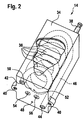
- an exemplary module 14 is shown that is useful with an electrical system 10 of the invention or for use in a method of the invention.
- the module 14 comprises a housing 34, in which a plurality of functional units or cells 36 are arranged. Due to their high energy density compared to other battery systems, lithium ion cells are favored for use according to the invention, with each module 14 preferably comprising only one type of cell.
- the module 14 may have a safety switch 38 (safety plug) for immediate voltage disconnection. This makes it possible for a fault in the electrical system 10 and / or maintenance to bring the voltage of the energy storage 12 immediately to zero, whereby a risk potential with respect to damage to the electrical system 10 as well as injury to persons can be reduced ,
- the exchange of individual modules 14 can be simplified by such a safety switch 38.
- the module 14 in particular on its housing 34 on a fast detachable connection to the total memory or energy storage 12.
- This connection can be designed, for example, as a plug connection or screw connection 40 in order to fix the module 14, for example, to a base support and / or to another module 14.
- the module 14 further includes an inlet 42 and an outlet 44 for an air conditioning fluid.
- an air conditioning fluid In order to direct the fluid in the module 14, further corresponding channels 46 are disposed within the housing 34 and connected to the inlet 42 and the outlet 44.
- a measuring port 48 for temperature measurement is further provided.
- the conditioning fluid could also be routed around the module 14, where the conditioning fluid could then be directed through several channels directly to the module surface.
- the module 14 has measuring connections 50, 52 for a voltage measurement. These are referred to as sens + and sens- connections, for example. With these connections, the voltage can be measured and thereby the dormitornde resistance value of the resistor 18 are calculated.
- the resistor 18 may be disposed within the housing 34 or outside the housing 34. It is essential that when using resistors 18 each module path 16, a resistor 18 is associated.
- the power output module has electrical connections 54, 56 connected to the power port 20. Also at these connections a voltage measurement is possible.
Claims (8)
- Procédé pour la commande de l'alimentation en énergie d'un moteur électrique, en particulier du moteur électrique d'un véhicule pouvant être entraîné électriquement, dans lequel un dispositif de commande (22) commande l'alimentation en énergie du moteur électrique grâce à un accumulateur d'énergie (12), et dans lequel l'accumulateur d'énergie (12) comprend une pluralité de modules (14) qui sont sollicités par des charges et/ou décharges répétées et sont soumis à un processus de vieillissement du fait de la sollicitation, caractérisé en ce que le dispositif de commande (22) commande la charge et/ou décharge d'au moins deux modules avec une différence telle que ces modules présentent une différence entre les courants circulant à travers ces modules afin de réduire sélectivement le processus de vieillissement du module moins sollicité, la différence étant une valeur moyenne de la différence entre les courants circulant à travers les modules en cas de charge ou décharge complète, les modules (14) étant respectivement disposés sur un trajet de module (16) et étant connectés en parallèle, la différence de charge et/ou de décharge des au moins deux modules (14) étant commandée grâce au réglage d'une valeur de résistance d'au moins une résistance variable (18) disposée sur le trajet de module (16).
- Procédé selon la revendication 1, caractérisé en ce que la valeur de résistance est réglée de telle sorte que la différence entre les courants circulant à travers les modules ne dépasse pas une valeur de 20%.
- Procédé selon l'une des revendications 1 ou 2, caractérisé en ce que la différence de charge et/ou décharge des au moins deux modules (14) est contrôlée respectivement par un ampèremètre (32) disposé sur le trajet de module (16) et/ou grâce à une mesure de la tension dans les modules (16) par le dispositif de commande (22).
- Procédé selon la revendication 3, caractérisé en ce que, sur la base de données d'une mesure de courant et/ou d'une mesure de tension, la valeur de résistance est réajustée.
- Procédé selon l'une des revendications 1 à 4, caractérisé en ce que le dispositif de commande (22) tient compte de la différence d'état de vieillissement des modules individuels (14) lors du choix de la sollicitation des modules à solliciter ou du module à solliciter.
- Procédé selon la revendication 5, caractérisé en ce que le dispositif de commande (22) évalue des données concernant la tension, la température et/ou le courant des modules (14) et calcule ce faisant en particulier la capacité et/ou la résistance interne des modules afin de tenir compte de l'état de vieillissement des modules (14).
- Procédé selon l'une des revendications 1 à 6, caractérisé en ce que l'on utilise des modules (14) qui présentent la même tension nominale.
- Système électrique, en particulier système électrique pour commander l'alimentation en énergie d'un véhicule pouvant être entraîné électriquement, comprenant un accumulateur d'énergie (12), en particulier pour entraîner un moteur électrique d'un véhicule, dans lequel l'accumulateur d'énergie (12) comprend une pluralité de modules (14) fixés de manière détachable et connectés en parallèle, disposés à chaque fois sur un trajet de module (16), dans lequel, sur le trajet de module (16), une résistance (18) avec une valeur de résistance réglable de manière variable est à chaque fois disposée, et comprenant un dispositif de commande (22) qui est adapté pour régler de manière ciblée la valeur de résistance.
Applications Claiming Priority (2)
| Application Number | Priority Date | Filing Date | Title |
|---|---|---|---|
| DE201010030885 DE102010030885A1 (de) | 2010-07-02 | 2010-07-02 | Verfahren zum Steuern der Energieversorgung eines Elektromotors |
| PCT/EP2011/061231 WO2012001176A1 (fr) | 2010-07-02 | 2011-07-04 | Procédé permettant de commander l'alimentation en énergie d'un moteur électrique |
Publications (2)
| Publication Number | Publication Date |
|---|---|
| EP2589103A1 EP2589103A1 (fr) | 2013-05-08 |
| EP2589103B1 true EP2589103B1 (fr) | 2016-01-20 |
Family
ID=44464606
Family Applications (1)
| Application Number | Title | Priority Date | Filing Date |
|---|---|---|---|
| EP11728883.7A Active EP2589103B1 (fr) | 2010-07-02 | 2011-07-04 | Procédé permettant de commander l'alimentation en énergie d'un moteur électrique |
Country Status (7)
| Country | Link |
|---|---|
| US (1) | US9184692B2 (fr) |
| EP (1) | EP2589103B1 (fr) |
| JP (1) | JP5595588B2 (fr) |
| KR (1) | KR101844752B1 (fr) |
| CN (1) | CN103026543B (fr) |
| DE (1) | DE102010030885A1 (fr) |
| WO (1) | WO2012001176A1 (fr) |
Cited By (1)
| Publication number | Priority date | Publication date | Assignee | Title |
|---|---|---|---|---|
| WO2021104721A1 (fr) * | 2019-11-27 | 2021-06-03 | Robert Bosch Gmbh | Diagnostic de batterie pour un véhicule à propulsion électrique |
Families Citing this family (10)
| Publication number | Priority date | Publication date | Assignee | Title |
|---|---|---|---|---|
| JP5583057B2 (ja) * | 2011-03-04 | 2014-09-03 | 三菱重工業株式会社 | 電池モジュール、組電池システム、電池調整方法およびプログラム |
| DE102011080881A1 (de) * | 2011-08-12 | 2013-02-14 | Siemens Ag | Elektrischer Speicher mit Teilspeichern |
| DE102014224169A1 (de) * | 2014-11-26 | 2016-06-02 | Robert Bosch Gmbh | Verfahren und Vorrichtung zum Ansteuern parallel geschalteter Leistungshalbleiterschalter |
| DE102015002148A1 (de) * | 2015-02-18 | 2016-08-18 | Audi Ag | Verfahren zum Betreiben von Batteriezellen einer Batterie, Batterie sowie Kraftfahrzeug |
| CN107797078A (zh) * | 2016-08-30 | 2018-03-13 | 中兴通讯股份有限公司 | 一种能量回馈式电源老化方法及其装置 |
| TWI615693B (zh) * | 2016-12-06 | 2018-02-21 | 財團法人資訊工業策進會 | 多軸機器手臂及其調整方法 |
| DE102016224548A1 (de) * | 2016-12-09 | 2018-06-14 | Robert Bosch Gmbh | Verfahren zum Betrieb eines elektrischen Energiespeichersystems sowie entsprechendes maschinenlesbares Speichermedium, elektronische Steuereinheit und elektrisches Energiespeichersystem |
| KR102221618B1 (ko) * | 2017-01-04 | 2021-03-02 | 한국전자통신연구원 | 배터리 모듈 및 이를 포함하는 전자 디바이스 |
| JP7191873B2 (ja) * | 2020-01-17 | 2022-12-19 | 株式会社東芝 | 充放電制御装置、充放電システム、充放電制御方法及び充放電制御プログラム |
| DE102020206520A1 (de) | 2020-05-26 | 2021-12-02 | Robert Bosch Gesellschaft mit beschränkter Haftung | Verfahren zum Betreiben eines Batteriesystems |
Family Cites Families (16)
| Publication number | Priority date | Publication date | Assignee | Title |
|---|---|---|---|---|
| JPS5736744U (fr) * | 1980-08-12 | 1982-02-26 | ||
| US5828201A (en) * | 1997-10-30 | 1998-10-27 | Lockheed Martin Corporation | Method for maintaining the charge capacity of traction battery modules of a hybrid electric vehicle |
| JP2003032908A (ja) * | 2001-07-19 | 2003-01-31 | Nisshinbo Ind Inc | キャパシタ組電池、その制御方法、その制御装置及び自動車用蓄電システム |
| DE10302860B4 (de) | 2003-01-22 | 2018-12-06 | Volkswagen Ag | Vorrichtung und Verfahren zum Ermitteln einer Strategie für das Betreiben einer Batterie |
| CN2865021Y (zh) * | 2005-12-28 | 2007-01-31 | 陈振富 | 均衡电池组 |
| US7212934B1 (en) * | 2006-03-06 | 2007-05-01 | United States Of America As Represented By The Administrator Of The National Aeronautics And Space Administration | String resistance detector |
| JP4572850B2 (ja) * | 2006-03-24 | 2010-11-04 | 株式会社日立製作所 | 電源制御装置 |
| JP2009044862A (ja) * | 2007-08-09 | 2009-02-26 | Toyota Motor Corp | 電気自動車の電源制御装置及び電源システム |
| JP5459946B2 (ja) * | 2007-09-28 | 2014-04-02 | 株式会社日立製作所 | 車両用直流電源装置 |
| JP5469813B2 (ja) * | 2008-01-29 | 2014-04-16 | 株式会社日立製作所 | 車両用電池システム |
| DE102008009568A1 (de) * | 2008-02-16 | 2009-08-20 | Bayerische Motoren Werke Aktiengesellschaft | Energieversorgungseinrichtung für ein Hybridfahrzeug und Verfahren zum Betrieb einer elektrischen Hochvolt-Energiespeichereinrichtung |
| JP4975715B2 (ja) * | 2008-11-20 | 2012-07-11 | 住友重機械工業株式会社 | 充放電制御装置 |
| CA2776694C (fr) * | 2009-10-05 | 2020-11-17 | The Regents Of The University Of California | Dispositifs, systemes et procedes pour le traitement de troubles neuropsychiatriques |
| KR101543039B1 (ko) * | 2009-10-26 | 2015-08-10 | 현대자동차주식회사 | 임피던스 매칭법을 이용한 인버터 커패시터 모듈의 회로 구성방법 |
| JP2011203595A (ja) * | 2010-03-26 | 2011-10-13 | Fujifilm Corp | 無線通信型カセッテのバッテリ管理装置およびシステム、並びに方法 |
| CN103299506B (zh) * | 2011-03-31 | 2016-03-09 | 松下电器产业株式会社 | 电力控制装置、电力控制方法、程序、集成电路及蓄电池模组 |
-
2010
- 2010-07-02 DE DE201010030885 patent/DE102010030885A1/de not_active Withdrawn
-
2011
- 2011-07-04 KR KR1020127034270A patent/KR101844752B1/ko active IP Right Grant
- 2011-07-04 EP EP11728883.7A patent/EP2589103B1/fr active Active
- 2011-07-04 CN CN201180032960.0A patent/CN103026543B/zh active Active
- 2011-07-04 WO PCT/EP2011/061231 patent/WO2012001176A1/fr active Application Filing
- 2011-07-04 US US13/807,652 patent/US9184692B2/en active Active
- 2011-07-04 JP JP2013517336A patent/JP5595588B2/ja active Active
Cited By (1)
| Publication number | Priority date | Publication date | Assignee | Title |
|---|---|---|---|---|
| WO2021104721A1 (fr) * | 2019-11-27 | 2021-06-03 | Robert Bosch Gmbh | Diagnostic de batterie pour un véhicule à propulsion électrique |
Also Published As
| Publication number | Publication date |
|---|---|
| CN103026543B (zh) | 2015-12-16 |
| JP2013535087A (ja) | 2013-09-09 |
| CN103026543A (zh) | 2013-04-03 |
| DE102010030885A1 (de) | 2012-01-05 |
| JP5595588B2 (ja) | 2014-09-24 |
| US20130200824A1 (en) | 2013-08-08 |
| EP2589103A1 (fr) | 2013-05-08 |
| KR20130120380A (ko) | 2013-11-04 |
| WO2012001176A1 (fr) | 2012-01-05 |
| KR101844752B1 (ko) | 2018-04-03 |
| US9184692B2 (en) | 2015-11-10 |
Similar Documents
| Publication | Publication Date | Title |
|---|---|---|
| EP2589103B1 (fr) | Procédé permettant de commander l'alimentation en énergie d'un moteur électrique | |
| DE10235458B4 (de) | Batteriesteuerungsverfahren und Batteriesteuerungsvorrichtung | |
| DE102013113951A1 (de) | Verfahren zum Detektieren von Leerlaufsspannungsverschiebungen mittels Optimierung durch Anpassen der Anodenelektrodenhalbzellspannungskurve | |
| DE102013217767B4 (de) | Batteriesatz-Ausgleichsvorrichtung | |
| DE102011113754B4 (de) | Überwachungsvorrichtung für die Energiekapazität und das Energiepotential eines Energiespeichersystems | |
| DE102011054144A1 (de) | Regelverfahren zur Detektion von übermäßigem Strom | |
| DE102012110555B4 (de) | Kombiniertes PI-Regelungs- und Vorsteuerverfahren für den Zellenladezustandsausgleich | |
| DE102013105119A1 (de) | Verfahren und Vorrichtung zum Laden von wiederaufladbaren Zellen | |
| EP2858849B1 (fr) | Procédé de détermination d'une résistance interne ohmique d'un module de batterie, système de gestion de batterie et véhicule à moteur | |
| DE102013108198B4 (de) | Verfahren zum Ausführen eines Zellausgleichs eines Batteriesystems basierend auf Kapazitätswerten | |
| EP3730958B1 (fr) | Procédé d'évaluation de l'état de santé d'une batterie haute tension et testeur de batterie | |
| DE102018200976A1 (de) | Verfahren zum Steuern des Ladens einer Batterieeinheit, Verfahren zum Laden einer Batterieeinheit, Steuereinheit, Ladesystem, Batteriesystem und Arbeitsvorrichtung | |
| DE102017002113A1 (de) | Unterseeboot und Verfahren zum Betreiben eines Antriebssystems eines Unterseebootes | |
| EP3708416A1 (fr) | Procédé et dispositif de charge permettant de déterminer une capacité d'accumulation maximale d'un accumulateur d'énergie | |
| WO2015078641A1 (fr) | Dispositif de stockage d'énergie électrique et procédé pour faire fonctionner un dispositif de stockage d'énergie électrique | |
| EP2617115B1 (fr) | Procédé de charge d'une batterie de véhicule à moteur | |
| DE112016002067T5 (de) | Verfahren und Überwachungseinheit zum Überwachen eines Batteriesystems | |
| DE102011087761B4 (de) | Verfahren zur Bestimmung eines Alterungszustands einer Batterieanordnung | |
| DE102014108601A1 (de) | Verfahren zum Anschließen mehrerer Batterieeinheiten an einen zweipoligen Eingang eines bidirektionalen Batteriewandlers sowie bidirektionaler Batteriewandler und Photovoltaikwechselrichter | |
| DE102012012765A1 (de) | Verfahren und Vorrichtung zum Laden eines elektrischen Energiespeichers | |
| DE102011103974A1 (de) | Verfahren und Vorrichtung zum Betrieb elektrochemischer Batterien | |
| DE102008053089A1 (de) | Akkumulator mit mehreren galvanischen Zellen | |
| DE102014224227A1 (de) | Betriebsstrategie für ein passives Mehr-Energiespeicher-Bordnetz | |
| DE102018112875A1 (de) | Verfahren zur Bestimmung von Eigenschaften von Batteriesegmenten zum Betrieb eines Batteriesatzes mit Modulen verschiedener chemischer Zusammensetzung | |
| EP3596800A1 (fr) | Charge d'un accumulateur |
Legal Events
| Date | Code | Title | Description |
|---|---|---|---|
| PUAI | Public reference made under article 153(3) epc to a published international application that has entered the european phase |
Free format text: ORIGINAL CODE: 0009012 |
|
| 17P | Request for examination filed |
Effective date: 20130204 |
|
| AK | Designated contracting states |
Kind code of ref document: A1 Designated state(s): AL AT BE BG CH CY CZ DE DK EE ES FI FR GB GR HR HU IE IS IT LI LT LU LV MC MK MT NL NO PL PT RO RS SE SI SK SM TR |
|
| DAX | Request for extension of the european patent (deleted) | ||
| 17Q | First examination report despatched |
Effective date: 20140513 |
|
| GRAP | Despatch of communication of intention to grant a patent |
Free format text: ORIGINAL CODE: EPIDOSNIGR1 |
|
| RIC1 | Information provided on ipc code assigned before grant |
Ipc: B60L 11/18 20060101ALI20150626BHEP Ipc: H01M 10/615 20140101ALN20150626BHEP Ipc: H01M 10/44 20060101AFI20150626BHEP Ipc: H01M 10/6567 20140101ALN20150626BHEP Ipc: H01M 10/613 20140101ALN20150626BHEP Ipc: H01M 10/6571 20140101ALN20150626BHEP Ipc: H02J 7/00 20060101ALI20150626BHEP Ipc: H01M 10/625 20140101ALN20150626BHEP Ipc: H01M 10/48 20060101ALI20150626BHEP |
|
| INTG | Intention to grant announced |
Effective date: 20150729 |
|
| GRAS | Grant fee paid |
Free format text: ORIGINAL CODE: EPIDOSNIGR3 |
|
| GRAA | (expected) grant |
Free format text: ORIGINAL CODE: 0009210 |
|
| AK | Designated contracting states |
Kind code of ref document: B1 Designated state(s): AL AT BE BG CH CY CZ DE DK EE ES FI FR GB GR HR HU IE IS IT LI LT LU LV MC MK MT NL NO PL PT RO RS SE SI SK SM TR |
|
| REG | Reference to a national code |
Ref country code: GB Ref legal event code: FG4D Free format text: NOT ENGLISH |
|
| REG | Reference to a national code |
Ref country code: CH Ref legal event code: EP |
|
| REG | Reference to a national code |
Ref country code: IE Ref legal event code: FG4D Free format text: LANGUAGE OF EP DOCUMENT: GERMAN |
|
| REG | Reference to a national code |
Ref country code: AT Ref legal event code: REF Ref document number: 772099 Country of ref document: AT Kind code of ref document: T Effective date: 20160215 |
|
| REG | Reference to a national code |
Ref country code: DE Ref legal event code: R096 Ref document number: 502011008726 Country of ref document: DE |
|
| REG | Reference to a national code |
Ref country code: LT Ref legal event code: MG4D Ref country code: NL Ref legal event code: MP Effective date: 20160120 |
|
| PG25 | Lapsed in a contracting state [announced via postgrant information from national office to epo] |
Ref country code: NL Free format text: LAPSE BECAUSE OF FAILURE TO SUBMIT A TRANSLATION OF THE DESCRIPTION OR TO PAY THE FEE WITHIN THE PRESCRIBED TIME-LIMIT Effective date: 20160120 |
|
| REG | Reference to a national code |
Ref country code: FR Ref legal event code: PLFP Year of fee payment: 6 |
|
| PG25 | Lapsed in a contracting state [announced via postgrant information from national office to epo] |
Ref country code: NO Free format text: LAPSE BECAUSE OF FAILURE TO SUBMIT A TRANSLATION OF THE DESCRIPTION OR TO PAY THE FEE WITHIN THE PRESCRIBED TIME-LIMIT Effective date: 20160420 Ref country code: HR Free format text: LAPSE BECAUSE OF FAILURE TO SUBMIT A TRANSLATION OF THE DESCRIPTION OR TO PAY THE FEE WITHIN THE PRESCRIBED TIME-LIMIT Effective date: 20160120 Ref country code: FI Free format text: LAPSE BECAUSE OF FAILURE TO SUBMIT A TRANSLATION OF THE DESCRIPTION OR TO PAY THE FEE WITHIN THE PRESCRIBED TIME-LIMIT Effective date: 20160120 Ref country code: GR Free format text: LAPSE BECAUSE OF FAILURE TO SUBMIT A TRANSLATION OF THE DESCRIPTION OR TO PAY THE FEE WITHIN THE PRESCRIBED TIME-LIMIT Effective date: 20160421 Ref country code: ES Free format text: LAPSE BECAUSE OF FAILURE TO SUBMIT A TRANSLATION OF THE DESCRIPTION OR TO PAY THE FEE WITHIN THE PRESCRIBED TIME-LIMIT Effective date: 20160120 |
|
| PG25 | Lapsed in a contracting state [announced via postgrant information from national office to epo] |
Ref country code: LT Free format text: LAPSE BECAUSE OF FAILURE TO SUBMIT A TRANSLATION OF THE DESCRIPTION OR TO PAY THE FEE WITHIN THE PRESCRIBED TIME-LIMIT Effective date: 20160120 Ref country code: SE Free format text: LAPSE BECAUSE OF FAILURE TO SUBMIT A TRANSLATION OF THE DESCRIPTION OR TO PAY THE FEE WITHIN THE PRESCRIBED TIME-LIMIT Effective date: 20160120 Ref country code: PT Free format text: LAPSE BECAUSE OF FAILURE TO SUBMIT A TRANSLATION OF THE DESCRIPTION OR TO PAY THE FEE WITHIN THE PRESCRIBED TIME-LIMIT Effective date: 20160520 Ref country code: LV Free format text: LAPSE BECAUSE OF FAILURE TO SUBMIT A TRANSLATION OF THE DESCRIPTION OR TO PAY THE FEE WITHIN THE PRESCRIBED TIME-LIMIT Effective date: 20160120 Ref country code: RS Free format text: LAPSE BECAUSE OF FAILURE TO SUBMIT A TRANSLATION OF THE DESCRIPTION OR TO PAY THE FEE WITHIN THE PRESCRIBED TIME-LIMIT Effective date: 20160120 Ref country code: PL Free format text: LAPSE BECAUSE OF FAILURE TO SUBMIT A TRANSLATION OF THE DESCRIPTION OR TO PAY THE FEE WITHIN THE PRESCRIBED TIME-LIMIT Effective date: 20160120 Ref country code: IS Free format text: LAPSE BECAUSE OF FAILURE TO SUBMIT A TRANSLATION OF THE DESCRIPTION OR TO PAY THE FEE WITHIN THE PRESCRIBED TIME-LIMIT Effective date: 20160520 |
|
| REG | Reference to a national code |
Ref country code: DE Ref legal event code: R097 Ref document number: 502011008726 Country of ref document: DE |
|
| PG25 | Lapsed in a contracting state [announced via postgrant information from national office to epo] |
Ref country code: EE Free format text: LAPSE BECAUSE OF FAILURE TO SUBMIT A TRANSLATION OF THE DESCRIPTION OR TO PAY THE FEE WITHIN THE PRESCRIBED TIME-LIMIT Effective date: 20160120 Ref country code: DK Free format text: LAPSE BECAUSE OF FAILURE TO SUBMIT A TRANSLATION OF THE DESCRIPTION OR TO PAY THE FEE WITHIN THE PRESCRIBED TIME-LIMIT Effective date: 20160120 |
|
| PLBE | No opposition filed within time limit |
Free format text: ORIGINAL CODE: 0009261 |
|
| STAA | Information on the status of an ep patent application or granted ep patent |
Free format text: STATUS: NO OPPOSITION FILED WITHIN TIME LIMIT |
|
| PG25 | Lapsed in a contracting state [announced via postgrant information from national office to epo] |
Ref country code: SK Free format text: LAPSE BECAUSE OF FAILURE TO SUBMIT A TRANSLATION OF THE DESCRIPTION OR TO PAY THE FEE WITHIN THE PRESCRIBED TIME-LIMIT Effective date: 20160120 Ref country code: RO Free format text: LAPSE BECAUSE OF FAILURE TO SUBMIT A TRANSLATION OF THE DESCRIPTION OR TO PAY THE FEE WITHIN THE PRESCRIBED TIME-LIMIT Effective date: 20160120 Ref country code: CZ Free format text: LAPSE BECAUSE OF FAILURE TO SUBMIT A TRANSLATION OF THE DESCRIPTION OR TO PAY THE FEE WITHIN THE PRESCRIBED TIME-LIMIT Effective date: 20160120 Ref country code: SM Free format text: LAPSE BECAUSE OF FAILURE TO SUBMIT A TRANSLATION OF THE DESCRIPTION OR TO PAY THE FEE WITHIN THE PRESCRIBED TIME-LIMIT Effective date: 20160120 |
|
| 26N | No opposition filed |
Effective date: 20161021 |
|
| PG25 | Lapsed in a contracting state [announced via postgrant information from national office to epo] |
Ref country code: BE Free format text: LAPSE BECAUSE OF NON-PAYMENT OF DUE FEES Effective date: 20160731 |
|
| PG25 | Lapsed in a contracting state [announced via postgrant information from national office to epo] |
Ref country code: SI Free format text: LAPSE BECAUSE OF FAILURE TO SUBMIT A TRANSLATION OF THE DESCRIPTION OR TO PAY THE FEE WITHIN THE PRESCRIBED TIME-LIMIT Effective date: 20160120 Ref country code: BG Free format text: LAPSE BECAUSE OF FAILURE TO SUBMIT A TRANSLATION OF THE DESCRIPTION OR TO PAY THE FEE WITHIN THE PRESCRIBED TIME-LIMIT Effective date: 20160420 |
|
| REG | Reference to a national code |
Ref country code: CH Ref legal event code: PL |
|
| GBPC | Gb: european patent ceased through non-payment of renewal fee |
Effective date: 20160704 |
|
| PG25 | Lapsed in a contracting state [announced via postgrant information from national office to epo] |
Ref country code: MC Free format text: LAPSE BECAUSE OF FAILURE TO SUBMIT A TRANSLATION OF THE DESCRIPTION OR TO PAY THE FEE WITHIN THE PRESCRIBED TIME-LIMIT Effective date: 20160120 |
|
| PG25 | Lapsed in a contracting state [announced via postgrant information from national office to epo] |
Ref country code: LI Free format text: LAPSE BECAUSE OF NON-PAYMENT OF DUE FEES Effective date: 20160731 Ref country code: CH Free format text: LAPSE BECAUSE OF NON-PAYMENT OF DUE FEES Effective date: 20160731 |
|
| REG | Reference to a national code |
Ref country code: IE Ref legal event code: MM4A |
|
| PG25 | Lapsed in a contracting state [announced via postgrant information from national office to epo] |
Ref country code: GB Free format text: LAPSE BECAUSE OF NON-PAYMENT OF DUE FEES Effective date: 20160704 |
|
| REG | Reference to a national code |
Ref country code: FR Ref legal event code: PLFP Year of fee payment: 7 |
|
| PG25 | Lapsed in a contracting state [announced via postgrant information from national office to epo] |
Ref country code: IE Free format text: LAPSE BECAUSE OF NON-PAYMENT OF DUE FEES Effective date: 20160704 |
|
| PG25 | Lapsed in a contracting state [announced via postgrant information from national office to epo] |
Ref country code: LU Free format text: LAPSE BECAUSE OF NON-PAYMENT OF DUE FEES Effective date: 20160704 |
|
| REG | Reference to a national code |
Ref country code: AT Ref legal event code: MM01 Ref document number: 772099 Country of ref document: AT Kind code of ref document: T Effective date: 20160704 |
|
| PG25 | Lapsed in a contracting state [announced via postgrant information from national office to epo] |
Ref country code: AT Free format text: LAPSE BECAUSE OF NON-PAYMENT OF DUE FEES Effective date: 20160704 |
|
| PG25 | Lapsed in a contracting state [announced via postgrant information from national office to epo] |
Ref country code: CY Free format text: LAPSE BECAUSE OF FAILURE TO SUBMIT A TRANSLATION OF THE DESCRIPTION OR TO PAY THE FEE WITHIN THE PRESCRIBED TIME-LIMIT Effective date: 20160120 Ref country code: HU Free format text: LAPSE BECAUSE OF FAILURE TO SUBMIT A TRANSLATION OF THE DESCRIPTION OR TO PAY THE FEE WITHIN THE PRESCRIBED TIME-LIMIT; INVALID AB INITIO Effective date: 20110704 |
|
| PG25 | Lapsed in a contracting state [announced via postgrant information from national office to epo] |
Ref country code: TR Free format text: LAPSE BECAUSE OF FAILURE TO SUBMIT A TRANSLATION OF THE DESCRIPTION OR TO PAY THE FEE WITHIN THE PRESCRIBED TIME-LIMIT Effective date: 20160120 Ref country code: MT Free format text: LAPSE BECAUSE OF FAILURE TO SUBMIT A TRANSLATION OF THE DESCRIPTION OR TO PAY THE FEE WITHIN THE PRESCRIBED TIME-LIMIT Effective date: 20160120 Ref country code: MK Free format text: LAPSE BECAUSE OF FAILURE TO SUBMIT A TRANSLATION OF THE DESCRIPTION OR TO PAY THE FEE WITHIN THE PRESCRIBED TIME-LIMIT Effective date: 20160120 |
|
| REG | Reference to a national code |
Ref country code: FR Ref legal event code: PLFP Year of fee payment: 8 |
|
| PG25 | Lapsed in a contracting state [announced via postgrant information from national office to epo] |
Ref country code: AL Free format text: LAPSE BECAUSE OF FAILURE TO SUBMIT A TRANSLATION OF THE DESCRIPTION OR TO PAY THE FEE WITHIN THE PRESCRIBED TIME-LIMIT Effective date: 20160120 |
|
| PGFP | Annual fee paid to national office [announced via postgrant information from national office to epo] |
Ref country code: IT Payment date: 20230731 Year of fee payment: 13 |
|
| PGFP | Annual fee paid to national office [announced via postgrant information from national office to epo] |
Ref country code: FR Payment date: 20230724 Year of fee payment: 13 Ref country code: DE Payment date: 20230922 Year of fee payment: 13 |