EP2588015B1 - Fixationssystem für knochen - Google Patents
Fixationssystem für knochen Download PDFInfo
- Publication number
- EP2588015B1 EP2588015B1 EP11730209.1A EP11730209A EP2588015B1 EP 2588015 B1 EP2588015 B1 EP 2588015B1 EP 11730209 A EP11730209 A EP 11730209A EP 2588015 B1 EP2588015 B1 EP 2588015B1
- Authority
- EP
- European Patent Office
- Prior art keywords
- bone
- rib
- round hole
- screw
- fixation system
- Prior art date
- Legal status (The legal status is an assumption and is not a legal conclusion. Google has not performed a legal analysis and makes no representation as to the accuracy of the status listed.)
- Active
Links
Images


Classifications
-
- A—HUMAN NECESSITIES
- A61—MEDICAL OR VETERINARY SCIENCE; HYGIENE
- A61B—DIAGNOSIS; SURGERY; IDENTIFICATION
- A61B17/00—Surgical instruments, devices or methods, e.g. tourniquets
- A61B17/56—Surgical instruments or methods for treatment of bones or joints; Devices specially adapted therefor
- A61B17/58—Surgical instruments or methods for treatment of bones or joints; Devices specially adapted therefor for osteosynthesis, e.g. bone plates, screws, setting implements or the like
- A61B17/68—Internal fixation devices, including fasteners and spinal fixators, even if a part thereof projects from the skin
- A61B17/84—Fasteners therefor or fasteners being internal fixation devices
- A61B17/86—Pins or screws or threaded wires; nuts therefor
- A61B17/8605—Heads, i.e. proximal ends projecting from bone
-
- A—HUMAN NECESSITIES
- A61—MEDICAL OR VETERINARY SCIENCE; HYGIENE
- A61B—DIAGNOSIS; SURGERY; IDENTIFICATION
- A61B17/00—Surgical instruments, devices or methods, e.g. tourniquets
- A61B17/56—Surgical instruments or methods for treatment of bones or joints; Devices specially adapted therefor
- A61B17/58—Surgical instruments or methods for treatment of bones or joints; Devices specially adapted therefor for osteosynthesis, e.g. bone plates, screws, setting implements or the like
- A61B17/68—Internal fixation devices, including fasteners and spinal fixators, even if a part thereof projects from the skin
- A61B17/80—Cortical plates, i.e. bone plates; Instruments for holding or positioning cortical plates, or for compressing bones attached to cortical plates
- A61B17/8004—Cortical plates, i.e. bone plates; Instruments for holding or positioning cortical plates, or for compressing bones attached to cortical plates with means for distracting or compressing the bone or bones
- A61B17/8014—Cortical plates, i.e. bone plates; Instruments for holding or positioning cortical plates, or for compressing bones attached to cortical plates with means for distracting or compressing the bone or bones the extension or compression force being caused by interaction of the plate hole and the screws
-
- A—HUMAN NECESSITIES
- A61—MEDICAL OR VETERINARY SCIENCE; HYGIENE
- A61B—DIAGNOSIS; SURGERY; IDENTIFICATION
- A61B17/00—Surgical instruments, devices or methods, e.g. tourniquets
- A61B17/56—Surgical instruments or methods for treatment of bones or joints; Devices specially adapted therefor
- A61B17/58—Surgical instruments or methods for treatment of bones or joints; Devices specially adapted therefor for osteosynthesis, e.g. bone plates, screws, setting implements or the like
- A61B17/68—Internal fixation devices, including fasteners and spinal fixators, even if a part thereof projects from the skin
- A61B17/80—Cortical plates, i.e. bone plates; Instruments for holding or positioning cortical plates, or for compressing bones attached to cortical plates
- A61B17/8052—Cortical plates, i.e. bone plates; Instruments for holding or positioning cortical plates, or for compressing bones attached to cortical plates immobilised relative to screws by interlocking form of the heads and plate holes, e.g. conical or threaded
-
- A—HUMAN NECESSITIES
- A61—MEDICAL OR VETERINARY SCIENCE; HYGIENE
- A61B—DIAGNOSIS; SURGERY; IDENTIFICATION
- A61B17/00—Surgical instruments, devices or methods, e.g. tourniquets
- A61B2017/00004—(bio)absorbable, (bio)resorbable, resorptive
Definitions
- the invention relates to a fixation system for bone with bone screws and a bone plate having a plurality of arranged in the direction of the plate longitudinal axis holes for receiving bone screws.
- a known bone plate ( EP 0760632 B1 ) are the holes to the top of the bone plate out all around spherical in order to support a bone screw with spherical bottom of the head in different angular positions can.
- the holes At the bottom of the plate adjacent to the bone, the holes have a smaller diameter portion with a partial thread to accommodate a bone screw with a cylindrical threaded head to be sunk perpendicular to the plane of the plate.
- EP 1158915 B1 and EP 1158916 B1 are elongated holes with an internal thread, which extends at one end of the slot from the top to the bottom of the bone plate and has a circumferential or central angle in the range of 190-280 ° exists.
- the internal thread occupies the entire depth of the slot, tapering towards the bottom of the Bone plate conical and has a cone angle in the range of 5 to 20 °.
- elongated holes are provided in the bone plate, which may be formed oval, elliptical or rectangular or include a combination of such forms; only circular holes have been explicitly excluded from this definition of the slot.
- the slot is combined with a circular hole and this is provided with a three-dimensional structuring, which is in the form of an internal thread or a peripheral lamella or lip. Shown is a conical female thread extending from the top to the bottom of the bone plate and having a circumferential or central angle in the range of 190 to 280 °.
- a fixation system for bones having a bone plate which has elongated holes as through-holes which, near their bottom adjacent to the bone, have projections which extend in the lower part of the oblong hole parallel to the plane of the plate.
- To the top of the bone plate there are seats for ball heads of the bone screws.
- the seats are designed as inwardly inclined conical surfaces or spherical surfaces.
- To cooperate with the projections in the bone plate the bone screw below the ball head has a short piece of thread that is capable of deforming and conforming the resilient projections in the slot.
- the seating surfaces of the bone plate and the bone screw make it possible to insert the bone screw in set different angular positions with respect to the axis of the through holes.
- the publication EP 1 859 752 A1 shows a fixation system, from which the preamble of claim 1 is derived, with a bone plate and a bone screw, which is suitable to compress the fragments of a bone with a screw and at the same time enter into a stable angle connection.
- the bone plate has elongated hole formations, which are partially provided with a thread with multiple threads.
- a support surface is arranged for a corresponding part of a lower portion of the head of the bone screw. Above the corresponding support surface of the bone screw, this has a head thread.
- the invention has for its object to provide a Fixationsssytem with bone screws and a bone plate, in which various bone screws - such Konussitz lake and those with ball seating surfaces - can be applied to meet the different requirements in fixing a broken or damaged bone.
- bone fragments should be able to be displaced relative to each other during fixation.
- the new fixation system consists of two types of bone screws and a bone plate, whereby with the first type bone screws only screwing perpendicular to the plate shape of the bone plate is possible, which has for this purpose a radial rib and a conical seat, while the second type bone screw can be worked at an angle to the plate plane, wherein no engagement of the bone screw in the radial Rib takes place.
- the second type of bone screw has part-spherical surfaces on the head bottom, but no thread for engagement in the bone plate.
- the bone plate has a preferably elongated plate body made of a first, tissue-compatible, stiff material, which determines a top and bottom and a longitudinal axis.
- Hole formations are provided transversely to the plane of the plate, which consist of a first, larger round hole and a second, smaller round hole, wherein the round holes intersect to form edges, between which a passage for the screw shaft of an obliquely placed bone screw is formed.
- a radial rib is provided, which starts from the hole conversion and extends in a plane towards the round hole center.
- the first type of bone screw is provided with thread on the screw head and may possibly be supported on the rib of the smaller round hole and screwed to the rib of the larger round hole, whereby deformation and mutual shape adaptation takes place.
- this deformation retains a permanent part even after the bone screw has been separated from the bone plate, which means that this deformation
- the purely elastic portion also includes plastic deformation.
- this plastically deformed, permanent portion of the deformation can be present solely in the bone screw, can be present alone in the bone plate or can also be present in both the bone screw and the bone plate.
- the plastic, remaining portion is in each case in a kind of groove or groove which has at least a depth of 10 ⁇ m, preferably of more than 100 ⁇ m and particularly preferably of more than 200 ⁇ m.
- the first, larger round hole on three sections namely an upper, Vietnamesekehlförmigen section above the circumferential rib, a central, Vietnamesekehlförmigen section below the circumferential rib and a lower, frusto-conical portion which tapers towards the underside of the plate body and its largest diameter is smaller than the diameter of the upper or middle section.
- the smaller round hole includes an upper portion with a sloped transition region toward the top of the plate, a central portion below the plane of the circumferential rib having an inclined-rounded surface, and a lower, cylindrical or conical portion having a diameter smaller than the diameter of the upper or middle portion ,
- bone screws of the first type can be used with a head in his provided with a screw thread and in its lower part with a conical seat, in such a way that when eccentric screwing perpendicular to the plane of the plate into a bone, a displacement of the head takes place relative to the hole formation, such that bone fragments approximate during fixing to each other can be.
- the new bone plate also allows the use of bone screws of the second kind with spherical seating surfaces on the underside of the screw head.
- Such spherical head screws can be screwed in at an angle to the bone plate, wherein the screw shaft is anchored in the bone and the fixation is done by conditioning the spherical seat of the head to matching seating surface of the bone plate.
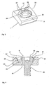
- the figures show the piece of a bone plate which consists of an elongate plate body 1 of a first, tissue-exporting, stiff material and in which a series of hole formations are mounted, of which a hole formation 2 is shown.
- the plate body 1 may be out of oblong oval or round or polygonal or adapted to its shape of the respective application.
- metals and their alloys are understood as tissue-contractual material, as are conventionally used for the production of implants.
- Preferred metals include titanium in any form, preferably also its alloys TiAl6V4 and TiCp .. Steels, such as implant steel, for example, the alloy 1.4441 are advantageously used.
- PLA is a biocompatible and resorbable plastic made of chemically bonded lactic acid molecules, which can be used like other resorbable plastics.
- bone plates for smaller and less stressed parts of the body are thinner and often less wide than bone plates of the larger and more heavily loaded parts, such as parts of the lower and thigh.
- the bone plate has an upper side 11 and a lower side 12, which are usually parallel to the plane of the plate, the lower side 12 being adjacent to the bone to be fixed.
- the hole formations 2 are lined up along the longitudinal axis of the elongated plate body 1 and consist of two stepped round holes, 21 and 22, which extend transversely to the plane of the plate and whose axes 21a, 22a intersect the longitudinal axis of the bone plate.
- the smallest diameter of the first round hole 21 is larger than the smallest diameter of the second round hole 22, and the distance of the two axes 21 a and 22 a from each other is smaller than the smallest diameter of the first round hole 21.
- an upper region 25 and a lower region 26 of the round hole 21 and an upper region 27 and a lower region 28 of the round hole 22 can be distinguished.
- the upper regions 25 and 27 are designed to be bowl-shaped, while the lower regions 26 and 28 form lateral surfaces with straight generatrices.
- the upper regions 25 and 27 have larger diameters than the lower regions 26 and 28.
- the lower region 26 forms a frusto-conical portion, which tapers towards the underside of the plate body 1.
- the lower region 28 is cylindrical, but it may also be frusto-conical.
- a radial rib 33 extends in a plane around the hole formation 2, starting from the hole walls.
- the rib 33 is formed as a circumferential ridge and has a wedge-shaped cross section, which tapers towards the center of the respective round hole. In plan view, the rib 33 appears to be similar to an eight.
- a ridge 61 is arranged parallel to the plane of the rib 33 at the outer edge of the larger round hole 21 for the attached to the larger round hole rib portion, whereby an edge 24 to the second round hole 22 forms.
- Starting from the Longitudinal axis of the plate body 1 increases the height of the ridge 61 to the edge of the plate body 1 toward, as best of the comparison of Fig. 4 With Fig. 3 evident.
- a passageway is formed, which favors the engagement of the external thread 41 of the cap screw 40.
- the larger round hole 21 has above the rib 33 has an upper, nikkehlförmigen portion 31 with or without ridge 61, and below the rib 33 are a middle, nikkehlförmiger section 36 and a lower, frusto-conical portion 26 is provided.
- the smaller round hole 22 comprises an upper portion 35 with an insertion slope 62, a central portion 36 with a sloping-rounded surface 63 below the plane of the rib 33, and a lower portion 28, which is preferably cylindrical, but may also be conical.
- the bone plate is designed to cooperate with at least two types of bone screws.
- the second type has a bone screw head with a part spherical bottom and can be supported with the head bottom on the inclined-rounded surface 63 of the bone plate.
- oblique position of the screw axis with respect to the plate plane is possible, both in the longitudinal direction and (to a small extent) in the transverse direction to the bone plate. This is made possible by the distance of the edges 23 from each other, which is greater than the diameter of the screw shaft of the bone screw.
- the first type of applicable bone screw 4 is shown in FIG Fig. 4 shown.
- This bone screw 4 has a screw head 40 with internal engagement and external thread 41 at the upper end and conical support surface 42 at the lower end, the cone inclination corresponds to the cone slope of the lower region 26 of the larger round hole 21.
- the external thread 41 may be cylindrical, but conical thread is preferred.
- the cone slope of the lower region 26 of the larger round hole 21 and the cone slope of the conical support surface 42 at the lower end of the screw head 40 of the bone screw has an angle relative to the longitudinal or symmetry axis of the bone screw or the round hole 21 in the range of 3 to 30 °.
- this cone angle is in a range of 6 to 20 °, and most preferably in a range of 8 to 12 °.
- a particularly preferred design has proven very effective with a cone angle of about 10 ° with high fatigue strength values and good solubility of the connection between bone screw and bone plate.
- the screw head 40 is followed by a screw shaft 43, which is intended to be anchored in a bone element to be fixed.
- the circumferential rib 33 extends in a plane, preferably parallel to the plane of the plate, while the external thread 41 extends along screw surfaces which are of course inclined relative to one another extend the plane of the radial rib 33, even if the bone screw 4 is intended to be screwed in parallel or concurrently with the axis 21 a of the round hole 21.
- the burr 61 is useful because it provides an abutment for the thread of the screw head.
- the mutual Formaripassung requires a certain flexibility of the (first) material of the bone plate at least in the region of the radial rib 33 and / or the (second) material of the bone screw at least in the region of the external thread 41. It is preferred to make the (second) material of the bone screw harder than the (first) material of the bone plate and also to choose a shape with a larger moment of resistance for the external thread 41 relative to the rib 33. In this way, the "softer" in-plane rib conforms largely to the engagement screw of the external thread 41 when the fixation system is used as intended. Nevertheless, it is also within the scope of the invention that at least in the area of the radial rib 33 and the external thread 41, the first and second material have the same hardness.
- the bone screw 4 can be used for mutual approach and compression of bone fragments.
- the bone screw 4 is attached with its axis parallel to the axis 22a in the region of the round hole 22.
- a lateral force on the screw head 40 which leads to a displacement of the bone fragment to be fixed relative to the bone plate.
- FIG. 5-8 Another particularly preferred embodiment of the bone plate is shown, wherein the same reference numerals are used for corresponding parts.
- the main difference is in the formation of the circumferential radial rib 33.
- This is partially cut away in the region of the smaller round hole 22 to provide an inclined-rounded sliding surface 35a and a transition surface 35b, which is used to guide the head of a bone screw with part-spherical underside of the head or to guide the screw with conical support surface 42 are useful.
- It is formed a locking rib 37 which increases to full size of the rib 33 in the region of the larger round hole 21.
- the remaining edge 34 extends less than 180 ° and thus allows the lateral introduction of bone screws from the smaller round hole 22 in the larger round hole 21st
- the rib 33 has a wedge-shaped cross section with an upper side inclined to the center of the hole and a lower side parallel to the plane of the plate. In this way, the moment of resistance of the rib 33 is significantly smaller than the moment of resistance of the external thread 41 in engagement with the rib, so the rib 33 so compliant, even if the materials of rib and fferwindung of equal hardness. However, a lower hardness of the rib 33 is preferred for purposes of conforming.
- a fixation system for bone with bone plate and bone screws is created in which bone screws with round head can be set at different angles of inclination to the bone plate. Furthermore, the fixation system allows for the use of bone screws with conical head, the relative displacement between bone fragment to be fixed and bone plate, which allows the surgeon to move bone fragments in their fixation against each other.
Landscapes
- Health & Medical Sciences (AREA)
- Orthopedic Medicine & Surgery (AREA)
- Surgery (AREA)
- Life Sciences & Earth Sciences (AREA)
- Heart & Thoracic Surgery (AREA)
- Nuclear Medicine, Radiotherapy & Molecular Imaging (AREA)
- Engineering & Computer Science (AREA)
- Biomedical Technology (AREA)
- Neurology (AREA)
- Medical Informatics (AREA)
- Molecular Biology (AREA)
- Animal Behavior & Ethology (AREA)
- General Health & Medical Sciences (AREA)
- Public Health (AREA)
- Veterinary Medicine (AREA)
- Surgical Instruments (AREA)
Priority Applications (2)
| Application Number | Priority Date | Filing Date | Title |
|---|---|---|---|
| EP16173279.7A EP3081180B1 (de) | 2010-06-30 | 2011-06-24 | Fixationssystem für knochen |
| PL11730209T PL2588015T3 (pl) | 2010-06-30 | 2011-06-24 | System unieruchamiania kości |
Applications Claiming Priority (2)
| Application Number | Priority Date | Filing Date | Title |
|---|---|---|---|
| DE102010025702.8A DE102010025702B4 (de) | 2010-06-30 | 2010-06-30 | Fixationssystem für Knochen mit Knochenplatte und Knochenschrauben |
| PCT/EP2011/003112 WO2012000627A1 (de) | 2010-06-30 | 2011-06-24 | Fixationssystem für knochen |
Related Child Applications (2)
| Application Number | Title | Priority Date | Filing Date |
|---|---|---|---|
| EP16173279.7A Division-Into EP3081180B1 (de) | 2010-06-30 | 2011-06-24 | Fixationssystem für knochen |
| EP16173279.7A Division EP3081180B1 (de) | 2010-06-30 | 2011-06-24 | Fixationssystem für knochen |
Publications (2)
| Publication Number | Publication Date |
|---|---|
| EP2588015A1 EP2588015A1 (de) | 2013-05-08 |
| EP2588015B1 true EP2588015B1 (de) | 2016-11-16 |
Family
ID=44503678
Family Applications (2)
| Application Number | Title | Priority Date | Filing Date |
|---|---|---|---|
| EP16173279.7A Active EP3081180B1 (de) | 2010-06-30 | 2011-06-24 | Fixationssystem für knochen |
| EP11730209.1A Active EP2588015B1 (de) | 2010-06-30 | 2011-06-24 | Fixationssystem für knochen |
Family Applications Before (1)
| Application Number | Title | Priority Date | Filing Date |
|---|---|---|---|
| EP16173279.7A Active EP3081180B1 (de) | 2010-06-30 | 2011-06-24 | Fixationssystem für knochen |
Country Status (7)
| Country | Link |
|---|---|
| EP (2) | EP3081180B1 (pt) |
| DE (1) | DE102010025702B4 (pt) |
| DK (1) | DK2588015T3 (pt) |
| ES (2) | ES2606560T3 (pt) |
| PL (1) | PL2588015T3 (pt) |
| PT (1) | PT2588015T (pt) |
| WO (1) | WO2012000627A1 (pt) |
Families Citing this family (12)
| Publication number | Priority date | Publication date | Assignee | Title |
|---|---|---|---|---|
| US20100256687A1 (en) | 2009-04-01 | 2010-10-07 | Merete Medical Gmbh | Fixation Device and Method of Use for a Ludloff Osteotomy Procedure |
| DE102009016394B4 (de) | 2009-04-07 | 2016-02-11 | Merete Medical Gmbh | Vorrichtung zur winkelstabilen Fixation und Kompression einer Bruchstelle bzw. Osteotomie an einem Knochen |
| WO2011076205A1 (de) | 2009-12-22 | 2011-06-30 | Merete Medical Gmbh | Knochenplattensystem für die osteosynthese |
| DE202011051165U1 (de) | 2011-08-31 | 2011-11-14 | Merete Medical Gmbh | Anatomisch angepasste, plantare Knochenplatte sowie Knochenplattensystem |
| DE102012103894B4 (de) | 2012-05-03 | 2016-10-27 | Merete Medical Gmbh | Knochenplattensystem für Osteosynthese |
| US9545276B2 (en) | 2013-03-15 | 2017-01-17 | Aristotech Industries Gmbh | Fixation device and method of use for a lapidus-type plantar hallux valgus procedure |
| USD745162S1 (en) | 2014-01-27 | 2015-12-08 | Merete Medical Gmbh | Bone plate |
| US10561450B2 (en) | 2015-02-26 | 2020-02-18 | Medartis Holding Ag | Bone plate and surgical kit for fixing bone fragments |
| US11197701B2 (en) | 2016-08-17 | 2021-12-14 | Globus Medical, Inc. | Stabilization systems |
| US10687873B2 (en) | 2016-08-17 | 2020-06-23 | Globus Medical Inc. | Stabilization systems |
| DE102021202281A1 (de) | 2021-03-09 | 2022-09-15 | Karl Leibinger Medizintechnik Gmbh & Co. Kg | Verankerbare Implantatanordnung |
| DE102022106581A1 (de) | 2022-03-21 | 2023-09-21 | Medical Magnesium GmbH | System zur Osteosynthese mit Knochenplatte und Knochenanker aus Magnesiumlegierungen |
Family Cites Families (13)
| Publication number | Priority date | Publication date | Assignee | Title |
|---|---|---|---|---|
| AU692846B2 (en) * | 1995-03-27 | 1998-06-18 | Synthes Gmbh | Bone plate |
| EP0848600B1 (de) * | 1995-09-06 | 2001-05-09 | SYNTHES AG Chur | Knochenplatte |
| DE19858889B4 (de) * | 1998-12-19 | 2008-08-07 | Wolter, Dietmar, Prof. Dr.Med. | Fixationssystem für Knochen |
| CA2626694C (en) | 1999-03-09 | 2011-08-02 | Synthes (U.S.A.) | Bone plate with conical screw threads |
| EP1158915B1 (de) | 1999-03-09 | 2004-09-01 | SYNTHES AG Chur | Knochenplatte |
| JP4162408B2 (ja) | 2000-01-27 | 2008-10-08 | ジンテーズ ゲゼルシャフト ミト ベシュレンクテル ハフツング | 骨板 |
| DE602004028451D1 (de) * | 2003-03-26 | 2010-09-16 | Swiss Orthopedic Solutions Sa | Fixierende knochenplatte |
| US8940028B2 (en) * | 2005-07-25 | 2015-01-27 | Smith & Nephew, Inc. | Systems and methods for using polyaxial plates |
| EP1649819A1 (de) * | 2004-10-19 | 2006-04-26 | Christian Maier | Knochenplatte |
| FR2880929B1 (fr) * | 2005-01-17 | 2007-03-30 | Didier Roux | Systeme de fixation du type par vis imperdable |
| ATE404129T1 (de) * | 2006-05-26 | 2008-08-15 | Aap Implantate Ag | Knochenplatte |
| US20080234749A1 (en) * | 2007-01-26 | 2008-09-25 | Zimmer Technology, Inc. | Bone plate providing threaded locking head screw capture |
| AR061999A1 (es) * | 2007-07-18 | 2008-08-10 | Pizzicara Mario Angel | Placa bloqueada de orificios combinados, control de estabilidad y doble angulacion, para union de huesos fracturados |
-
2010
- 2010-06-30 DE DE102010025702.8A patent/DE102010025702B4/de active Active
-
2011
- 2011-06-24 EP EP16173279.7A patent/EP3081180B1/de active Active
- 2011-06-24 EP EP11730209.1A patent/EP2588015B1/de active Active
- 2011-06-24 PT PT117302091T patent/PT2588015T/pt unknown
- 2011-06-24 ES ES11730209.1T patent/ES2606560T3/es active Active
- 2011-06-24 ES ES16173279T patent/ES2841375T3/es active Active
- 2011-06-24 DK DK11730209.1T patent/DK2588015T3/en active
- 2011-06-24 PL PL11730209T patent/PL2588015T3/pl unknown
- 2011-06-24 WO PCT/EP2011/003112 patent/WO2012000627A1/de active Application Filing
Also Published As
| Publication number | Publication date |
|---|---|
| DK2588015T3 (en) | 2017-02-20 |
| ES2606560T3 (es) | 2017-03-24 |
| EP2588015A1 (de) | 2013-05-08 |
| WO2012000627A1 (de) | 2012-01-05 |
| ES2841375T3 (es) | 2021-07-08 |
| EP3081180A1 (de) | 2016-10-19 |
| PT2588015T (pt) | 2017-02-21 |
| EP3081180B1 (de) | 2020-10-21 |
| DE102010025702B4 (de) | 2016-08-18 |
| PL2588015T3 (pl) | 2017-05-31 |
| DE102010025702A1 (de) | 2012-01-05 |
Similar Documents
| Publication | Publication Date | Title |
|---|---|---|
| EP2588015B1 (de) | Fixationssystem für knochen | |
| EP2584983B1 (de) | Knochenplatte sowie fixationssystem mit knochenplatte | |
| EP1800615B1 (de) | Knochenplatte | |
| EP2218415B1 (de) | Knochenschraube und Herstellungsverfahren hierfür | |
| EP1568329B1 (de) | Knochenverankerungselement | |
| EP0291632B1 (de) | Kleinknochenplatte, insbesondere für die Versorgung von Frakturen des Schädel- und Gesichtsskeletts oder dergleichen | |
| DE102005004841B4 (de) | Osteosyntheseplatte mit einer Vielzahl von Bohrungen zur Aufnahme von Knochenschrauben | |
| DE202011106835U1 (de) | Knochenplatte | |
| EP2844169B1 (de) | Knochenplattensystem für osteosynthese | |
| WO2004086990A1 (de) | Aufnahme für ein verblockungselement und verblockungselement | |
| WO2013021033A1 (de) | System aus einer knochenplatte und einer knochenschraube | |
| WO2016142502A1 (de) | Knochenplatte mit einer knochenschraube | |
| WO2006072284A1 (de) | Variabel winkelstabile schraubverbindung für die osteosynthese | |
| EP3416575B1 (de) | Vorrichtung zur knochenfixation | |
| EP1859752B1 (de) | Knochenplatte | |
| EP1935360A1 (de) | Plattenimplantat, insbesondere für die Anwendung an einer Wirbelsäule, mit einem Schraubenverschlusssystem | |
| DE202007002190U1 (de) | Teilzylindrische Knochenplatte zur winkelstabilen Fixation | |
| DE102010025000B4 (de) | Knochenplatte | |
| WO2008003313A2 (de) | Osteosynthesisches fixationssystem | |
| DE102010064626B3 (de) | Knochenplatte | |
| AT508196B1 (de) | Fixierungssystem für knochen mit konvexem bohrloch | |
| EP3501437A1 (de) | Knochenplatte und verfahren zum herstellen einer knochenplatte |
Legal Events
| Date | Code | Title | Description |
|---|---|---|---|
| PUAI | Public reference made under article 153(3) epc to a published international application that has entered the european phase |
Free format text: ORIGINAL CODE: 0009012 |
|
| 17P | Request for examination filed |
Effective date: 20130103 |
|
| AK | Designated contracting states |
Kind code of ref document: A1 Designated state(s): AL AT BE BG CH CY CZ DE DK EE ES FI FR GB GR HR HU IE IS IT LI LT LU LV MC MK MT NL NO PL PT RO RS SE SI SK SM TR |
|
| DAX | Request for extension of the european patent (deleted) | ||
| 17Q | First examination report despatched |
Effective date: 20140515 |
|
| RIC1 | Information provided on ipc code assigned before grant |
Ipc: A61B 17/80 20060101AFI20160427BHEP Ipc: A61B 17/86 20060101ALI20160427BHEP Ipc: A61B 17/00 20060101ALI20160427BHEP |
|
| GRAP | Despatch of communication of intention to grant a patent |
Free format text: ORIGINAL CODE: EPIDOSNIGR1 |
|
| INTG | Intention to grant announced |
Effective date: 20160708 |
|
| GRAS | Grant fee paid |
Free format text: ORIGINAL CODE: EPIDOSNIGR3 |
|
| GRAA | (expected) grant |
Free format text: ORIGINAL CODE: 0009210 |
|
| REG | Reference to a national code |
Ref country code: SE Ref legal event code: TRGR |
|
| AK | Designated contracting states |
Kind code of ref document: B1 Designated state(s): AL AT BE BG CH CY CZ DE DK EE ES FI FR GB GR HR HU IE IS IT LI LT LU LV MC MK MT NL NO PL PT RO RS SE SI SK SM TR |
|
| REG | Reference to a national code |
Ref country code: GB Ref legal event code: FG4D Free format text: NOT ENGLISH |
|
| REG | Reference to a national code |
Ref country code: CH Ref legal event code: NV Representative=s name: BOVARD AG, CH Ref country code: CH Ref legal event code: EP |
|
| REG | Reference to a national code |
Ref country code: IE Ref legal event code: FG4D Free format text: LANGUAGE OF EP DOCUMENT: GERMAN |
|
| REG | Reference to a national code |
Ref country code: AT Ref legal event code: REF Ref document number: 845138 Country of ref document: AT Kind code of ref document: T Effective date: 20161215 |
|
| REG | Reference to a national code |
Ref country code: DE Ref legal event code: R096 Ref document number: 502011011152 Country of ref document: DE |
|
| REG | Reference to a national code |
Ref country code: DK Ref legal event code: T3 Effective date: 20170214 |
|
| REG | Reference to a national code |
Ref country code: PT Ref legal event code: SC4A Ref document number: 2588015 Country of ref document: PT Date of ref document: 20170221 Kind code of ref document: T Free format text: AVAILABILITY OF NATIONAL TRANSLATION Effective date: 20170214 |
|
| PG25 | Lapsed in a contracting state [announced via postgrant information from national office to epo] |
Ref country code: LV Free format text: LAPSE BECAUSE OF FAILURE TO SUBMIT A TRANSLATION OF THE DESCRIPTION OR TO PAY THE FEE WITHIN THE PRESCRIBED TIME-LIMIT Effective date: 20161116 |
|
| REG | Reference to a national code |
Ref country code: NL Ref legal event code: FP |
|
| REG | Reference to a national code |
Ref country code: LT Ref legal event code: MG4D |
|
| REG | Reference to a national code |
Ref country code: NO Ref legal event code: T2 Effective date: 20161116 |
|
| PG25 | Lapsed in a contracting state [announced via postgrant information from national office to epo] |
Ref country code: GR Free format text: LAPSE BECAUSE OF FAILURE TO SUBMIT A TRANSLATION OF THE DESCRIPTION OR TO PAY THE FEE WITHIN THE PRESCRIBED TIME-LIMIT Effective date: 20170217 Ref country code: LT Free format text: LAPSE BECAUSE OF FAILURE TO SUBMIT A TRANSLATION OF THE DESCRIPTION OR TO PAY THE FEE WITHIN THE PRESCRIBED TIME-LIMIT Effective date: 20161116 |
|
| PG25 | Lapsed in a contracting state [announced via postgrant information from national office to epo] |
Ref country code: HR Free format text: LAPSE BECAUSE OF FAILURE TO SUBMIT A TRANSLATION OF THE DESCRIPTION OR TO PAY THE FEE WITHIN THE PRESCRIBED TIME-LIMIT Effective date: 20161116 Ref country code: RS Free format text: LAPSE BECAUSE OF FAILURE TO SUBMIT A TRANSLATION OF THE DESCRIPTION OR TO PAY THE FEE WITHIN THE PRESCRIBED TIME-LIMIT Effective date: 20161116 Ref country code: FI Free format text: LAPSE BECAUSE OF FAILURE TO SUBMIT A TRANSLATION OF THE DESCRIPTION OR TO PAY THE FEE WITHIN THE PRESCRIBED TIME-LIMIT Effective date: 20161116 |
|
| REG | Reference to a national code |
Ref country code: FR Ref legal event code: PLFP Year of fee payment: 7 |
|
| PG25 | Lapsed in a contracting state [announced via postgrant information from national office to epo] |
Ref country code: EE Free format text: LAPSE BECAUSE OF FAILURE TO SUBMIT A TRANSLATION OF THE DESCRIPTION OR TO PAY THE FEE WITHIN THE PRESCRIBED TIME-LIMIT Effective date: 20161116 Ref country code: SK Free format text: LAPSE BECAUSE OF FAILURE TO SUBMIT A TRANSLATION OF THE DESCRIPTION OR TO PAY THE FEE WITHIN THE PRESCRIBED TIME-LIMIT Effective date: 20161116 Ref country code: RO Free format text: LAPSE BECAUSE OF FAILURE TO SUBMIT A TRANSLATION OF THE DESCRIPTION OR TO PAY THE FEE WITHIN THE PRESCRIBED TIME-LIMIT Effective date: 20161116 |
|
| REG | Reference to a national code |
Ref country code: DE Ref legal event code: R097 Ref document number: 502011011152 Country of ref document: DE |
|
| PG25 | Lapsed in a contracting state [announced via postgrant information from national office to epo] |
Ref country code: SM Free format text: LAPSE BECAUSE OF FAILURE TO SUBMIT A TRANSLATION OF THE DESCRIPTION OR TO PAY THE FEE WITHIN THE PRESCRIBED TIME-LIMIT Effective date: 20161116 |
|
| PLBE | No opposition filed within time limit |
Free format text: ORIGINAL CODE: 0009261 |
|
| STAA | Information on the status of an ep patent application or granted ep patent |
Free format text: STATUS: NO OPPOSITION FILED WITHIN TIME LIMIT |
|
| 26N | No opposition filed |
Effective date: 20170817 |
|
| PG25 | Lapsed in a contracting state [announced via postgrant information from national office to epo] |
Ref country code: SI Free format text: LAPSE BECAUSE OF FAILURE TO SUBMIT A TRANSLATION OF THE DESCRIPTION OR TO PAY THE FEE WITHIN THE PRESCRIBED TIME-LIMIT Effective date: 20161116 |
|
| PG25 | Lapsed in a contracting state [announced via postgrant information from national office to epo] |
Ref country code: MC Free format text: LAPSE BECAUSE OF FAILURE TO SUBMIT A TRANSLATION OF THE DESCRIPTION OR TO PAY THE FEE WITHIN THE PRESCRIBED TIME-LIMIT Effective date: 20161116 |
|
| PG25 | Lapsed in a contracting state [announced via postgrant information from national office to epo] |
Ref country code: LU Free format text: LAPSE BECAUSE OF NON-PAYMENT OF DUE FEES Effective date: 20170624 |
|
| REG | Reference to a national code |
Ref country code: FR Ref legal event code: PLFP Year of fee payment: 8 |
|
| PG25 | Lapsed in a contracting state [announced via postgrant information from national office to epo] |
Ref country code: MT Free format text: LAPSE BECAUSE OF FAILURE TO SUBMIT A TRANSLATION OF THE DESCRIPTION OR TO PAY THE FEE WITHIN THE PRESCRIBED TIME-LIMIT Effective date: 20161116 |
|
| PG25 | Lapsed in a contracting state [announced via postgrant information from national office to epo] |
Ref country code: HU Free format text: LAPSE BECAUSE OF FAILURE TO SUBMIT A TRANSLATION OF THE DESCRIPTION OR TO PAY THE FEE WITHIN THE PRESCRIBED TIME-LIMIT; INVALID AB INITIO Effective date: 20110624 |
|
| REG | Reference to a national code |
Ref country code: DE Ref legal event code: R082 Ref document number: 502011011152 Country of ref document: DE Representative=s name: AUGSPURGER - TESCH - FRIDERICHS PATENT- UND RE, DE |
|
| PGFP | Annual fee paid to national office [announced via postgrant information from national office to epo] |
Ref country code: NL Payment date: 20190619 Year of fee payment: 9 Ref country code: DK Payment date: 20190624 Year of fee payment: 9 Ref country code: PT Payment date: 20190617 Year of fee payment: 9 Ref country code: NO Payment date: 20190620 Year of fee payment: 9 Ref country code: PL Payment date: 20190613 Year of fee payment: 9 Ref country code: IE Payment date: 20190621 Year of fee payment: 9 Ref country code: CZ Payment date: 20190620 Year of fee payment: 9 |
|
| PGFP | Annual fee paid to national office [announced via postgrant information from national office to epo] |
Ref country code: SE Payment date: 20190624 Year of fee payment: 9 Ref country code: BE Payment date: 20190619 Year of fee payment: 9 Ref country code: TR Payment date: 20190618 Year of fee payment: 9 Ref country code: BG Payment date: 20190619 Year of fee payment: 9 |
|
| PGFP | Annual fee paid to national office [announced via postgrant information from national office to epo] |
Ref country code: CH Payment date: 20190624 Year of fee payment: 9 |
|
| PG25 | Lapsed in a contracting state [announced via postgrant information from national office to epo] |
Ref country code: CY Free format text: LAPSE BECAUSE OF NON-PAYMENT OF DUE FEES Effective date: 20161116 |
|
| PGFP | Annual fee paid to national office [announced via postgrant information from national office to epo] |
Ref country code: GB Payment date: 20190624 Year of fee payment: 9 |
|
| PG25 | Lapsed in a contracting state [announced via postgrant information from national office to epo] |
Ref country code: MK Free format text: LAPSE BECAUSE OF FAILURE TO SUBMIT A TRANSLATION OF THE DESCRIPTION OR TO PAY THE FEE WITHIN THE PRESCRIBED TIME-LIMIT Effective date: 20161116 |
|
| PG25 | Lapsed in a contracting state [announced via postgrant information from national office to epo] |
Ref country code: AL Free format text: LAPSE BECAUSE OF FAILURE TO SUBMIT A TRANSLATION OF THE DESCRIPTION OR TO PAY THE FEE WITHIN THE PRESCRIBED TIME-LIMIT Effective date: 20161116 Ref country code: IS Free format text: LAPSE BECAUSE OF FAILURE TO SUBMIT A TRANSLATION OF THE DESCRIPTION OR TO PAY THE FEE WITHIN THE PRESCRIBED TIME-LIMIT Effective date: 20170316 |
|
| REG | Reference to a national code |
Ref country code: DK Ref legal event code: EBP Effective date: 20200630 Ref country code: NO Ref legal event code: MMEP |
|
| PG25 | Lapsed in a contracting state [announced via postgrant information from national office to epo] |
Ref country code: CZ Free format text: LAPSE BECAUSE OF NON-PAYMENT OF DUE FEES Effective date: 20200624 |
|
| REG | Reference to a national code |
Ref country code: CH Ref legal event code: PL |
|
| REG | Reference to a national code |
Ref country code: NL Ref legal event code: MM Effective date: 20200701 |
|
| REG | Reference to a national code |
Ref country code: AT Ref legal event code: MM01 Ref document number: 845138 Country of ref document: AT Kind code of ref document: T Effective date: 20200624 |
|
| GBPC | Gb: european patent ceased through non-payment of renewal fee |
Effective date: 20200624 |
|
| REG | Reference to a national code |
Ref country code: BE Ref legal event code: MM Effective date: 20200630 |
|
| PG25 | Lapsed in a contracting state [announced via postgrant information from national office to epo] |
Ref country code: CH Free format text: LAPSE BECAUSE OF NON-PAYMENT OF DUE FEES Effective date: 20200630 Ref country code: LI Free format text: LAPSE BECAUSE OF NON-PAYMENT OF DUE FEES Effective date: 20200630 Ref country code: IE Free format text: LAPSE BECAUSE OF NON-PAYMENT OF DUE FEES Effective date: 20200624 Ref country code: PT Free format text: LAPSE BECAUSE OF NON-PAYMENT OF DUE FEES Effective date: 20210127 Ref country code: NO Free format text: LAPSE BECAUSE OF NON-PAYMENT OF DUE FEES Effective date: 20200630 Ref country code: NL Free format text: LAPSE BECAUSE OF NON-PAYMENT OF DUE FEES Effective date: 20200701 Ref country code: GB Free format text: LAPSE BECAUSE OF NON-PAYMENT OF DUE FEES Effective date: 20200624 |
|
| PG25 | Lapsed in a contracting state [announced via postgrant information from national office to epo] |
Ref country code: SE Free format text: LAPSE BECAUSE OF NON-PAYMENT OF DUE FEES Effective date: 20200625 Ref country code: AT Free format text: LAPSE BECAUSE OF NON-PAYMENT OF DUE FEES Effective date: 20200624 Ref country code: BE Free format text: LAPSE BECAUSE OF NON-PAYMENT OF DUE FEES Effective date: 20200630 Ref country code: BG Free format text: LAPSE BECAUSE OF NON-PAYMENT OF DUE FEES Effective date: 20201231 |
|
| PG25 | Lapsed in a contracting state [announced via postgrant information from national office to epo] |
Ref country code: DK Free format text: LAPSE BECAUSE OF NON-PAYMENT OF DUE FEES Effective date: 20200630 |
|
| REG | Reference to a national code |
Ref country code: SE Ref legal event code: EUG |
|
| PG25 | Lapsed in a contracting state [announced via postgrant information from national office to epo] |
Ref country code: TR Free format text: LAPSE BECAUSE OF NON-PAYMENT OF DUE FEES Effective date: 20200624 |
|
| PG25 | Lapsed in a contracting state [announced via postgrant information from national office to epo] |
Ref country code: PL Free format text: LAPSE BECAUSE OF NON-PAYMENT OF DUE FEES Effective date: 20200624 |
|
| P01 | Opt-out of the competence of the unified patent court (upc) registered |
Effective date: 20230525 |
|
| PGFP | Annual fee paid to national office [announced via postgrant information from national office to epo] |
Ref country code: FR Payment date: 20230621 Year of fee payment: 13 Ref country code: DE Payment date: 20230620 Year of fee payment: 13 |
|
| PGFP | Annual fee paid to national office [announced via postgrant information from national office to epo] |
Ref country code: IT Payment date: 20230630 Year of fee payment: 13 Ref country code: ES Payment date: 20230719 Year of fee payment: 13 |