EP2587993B1 - Ultraschallsensor für einen kardiotokographen - Google Patents
Ultraschallsensor für einen kardiotokographen Download PDFInfo
- Publication number
- EP2587993B1 EP2587993B1 EP11728854.8A EP11728854A EP2587993B1 EP 2587993 B1 EP2587993 B1 EP 2587993B1 EP 11728854 A EP11728854 A EP 11728854A EP 2587993 B1 EP2587993 B1 EP 2587993B1
- Authority
- EP
- European Patent Office
- Prior art keywords
- ultrasonic sensor
- ctg
- imaging
- magnetic resonance
- cardiotocography
- Prior art date
- Legal status (The legal status is an assumption and is not a legal conclusion. Google has not performed a legal analysis and makes no representation as to the accuracy of the status listed.)
- Not-in-force
Links
Images


Classifications
-
- A—HUMAN NECESSITIES
- A61—MEDICAL OR VETERINARY SCIENCE; HYGIENE
- A61B—DIAGNOSIS; SURGERY; IDENTIFICATION
- A61B8/00—Diagnosis using ultrasonic, sonic or infrasonic waves
- A61B8/44—Constructional features of the ultrasonic, sonic or infrasonic diagnostic device
- A61B8/4444—Constructional features of the ultrasonic, sonic or infrasonic diagnostic device related to the probe
-
- A—HUMAN NECESSITIES
- A61—MEDICAL OR VETERINARY SCIENCE; HYGIENE
- A61B—DIAGNOSIS; SURGERY; IDENTIFICATION
- A61B5/00—Measuring for diagnostic purposes; Identification of persons
- A61B5/03—Measuring fluid pressure within the body other than blood pressure, e.g. cerebral pressure ; Measuring pressure in body tissues or organs
- A61B5/033—Uterine pressure
-
- A—HUMAN NECESSITIES
- A61—MEDICAL OR VETERINARY SCIENCE; HYGIENE
- A61B—DIAGNOSIS; SURGERY; IDENTIFICATION
- A61B5/00—Measuring for diagnostic purposes; Identification of persons
- A61B5/05—Detecting, measuring or recording for diagnosis by means of electric currents or magnetic fields; Measuring using microwaves or radio waves
- A61B5/055—Detecting, measuring or recording for diagnosis by means of electric currents or magnetic fields; Measuring using microwaves or radio waves involving electronic [EMR] or nuclear [NMR] magnetic resonance, e.g. magnetic resonance imaging
-
- A—HUMAN NECESSITIES
- A61—MEDICAL OR VETERINARY SCIENCE; HYGIENE
- A61B—DIAGNOSIS; SURGERY; IDENTIFICATION
- A61B8/00—Diagnosis using ultrasonic, sonic or infrasonic waves
- A61B8/02—Measuring pulse or heart rate
-
- A—HUMAN NECESSITIES
- A61—MEDICAL OR VETERINARY SCIENCE; HYGIENE
- A61B—DIAGNOSIS; SURGERY; IDENTIFICATION
- A61B8/00—Diagnosis using ultrasonic, sonic or infrasonic waves
- A61B8/08—Clinical applications
- A61B8/0866—Clinical applications involving foetal diagnosis; pre-natal or peri-natal diagnosis of the baby
-
- A—HUMAN NECESSITIES
- A61—MEDICAL OR VETERINARY SCIENCE; HYGIENE
- A61B—DIAGNOSIS; SURGERY; IDENTIFICATION
- A61B8/00—Diagnosis using ultrasonic, sonic or infrasonic waves
- A61B8/44—Constructional features of the ultrasonic, sonic or infrasonic diagnostic device
- A61B8/4444—Constructional features of the ultrasonic, sonic or infrasonic diagnostic device related to the probe
- A61B8/4455—Features of the external shape of the probe, e.g. ergonomic aspects
-
- A—HUMAN NECESSITIES
- A61—MEDICAL OR VETERINARY SCIENCE; HYGIENE
- A61B—DIAGNOSIS; SURGERY; IDENTIFICATION
- A61B8/00—Diagnosis using ultrasonic, sonic or infrasonic waves
- A61B8/44—Constructional features of the ultrasonic, sonic or infrasonic diagnostic device
- A61B8/4444—Constructional features of the ultrasonic, sonic or infrasonic diagnostic device related to the probe
- A61B8/4472—Wireless probes
-
- G—PHYSICS
- G01—MEASURING; TESTING
- G01R—MEASURING ELECTRIC VARIABLES; MEASURING MAGNETIC VARIABLES
- G01R33/00—Arrangements or instruments for measuring magnetic variables
- G01R33/20—Arrangements or instruments for measuring magnetic variables involving magnetic resonance
- G01R33/44—Arrangements or instruments for measuring magnetic variables involving magnetic resonance using nuclear magnetic resonance [NMR]
- G01R33/48—NMR imaging systems
- G01R33/4808—Multimodal MR, e.g. MR combined with positron emission tomography [PET], MR combined with ultrasound or MR combined with computed tomography [CT]
- G01R33/4814—MR combined with ultrasound
-
- G—PHYSICS
- G01—MEASURING; TESTING
- G01R—MEASURING ELECTRIC VARIABLES; MEASURING MAGNETIC VARIABLES
- G01R33/00—Arrangements or instruments for measuring magnetic variables
- G01R33/20—Arrangements or instruments for measuring magnetic variables involving magnetic resonance
- G01R33/44—Arrangements or instruments for measuring magnetic variables involving magnetic resonance using nuclear magnetic resonance [NMR]
- G01R33/48—NMR imaging systems
- G01R33/54—Signal processing systems, e.g. using pulse sequences ; Generation or control of pulse sequences; Operator console
- G01R33/56—Image enhancement or correction, e.g. subtraction or averaging techniques, e.g. improvement of signal-to-noise ratio and resolution
- G01R33/567—Image enhancement or correction, e.g. subtraction or averaging techniques, e.g. improvement of signal-to-noise ratio and resolution gated by physiological signals, i.e. synchronization of acquired MR data with periodical motion of an object of interest, e.g. monitoring or triggering system for cardiac or respiratory gating
- G01R33/5673—Gating or triggering based on a physiological signal other than an MR signal, e.g. ECG gating or motion monitoring using optical systems for monitoring the motion of a fiducial marker
-
- A—HUMAN NECESSITIES
- A61—MEDICAL OR VETERINARY SCIENCE; HYGIENE
- A61B—DIAGNOSIS; SURGERY; IDENTIFICATION
- A61B2562/00—Details of sensors; Constructional details of sensor housings or probes; Accessories for sensors
- A61B2562/22—Arrangements of medical sensors with cables or leads; Connectors or couplings specifically adapted for medical sensors
- A61B2562/221—Arrangements of sensors with cables or leads, e.g. cable harnesses
- A61B2562/222—Electrical cables or leads therefor, e.g. coaxial cables or ribbon cables
Definitions
- the invention relates to an ultrasonic sensor for cardiotocography (CTG).
- CTG cardiotocography
- the invention relates to a CTG ultrasound sensor which can be used in a magnetic resonance tomograph (MRT).
- MRT magnetic resonance tomograph
- the invention relates to a cardiotocograph, i. a CTG device with such an ultrasonic sensor and a system of an MRI and a CTG device with such an ultrasonic sensor.
- the WO 95/02361 describes an MRI system in which an ultrasound sensor can be used to provide blood flow velocity information and to obtain a trigger signal for MRI imaging.
- an ultrasonic sensor made of non-magnetic materials is used.
- the ultrasound sensor is used outside the imaging range of the MRI, in particular in the area of the carotid artery.
- ultrasound-based sensors to trigger the imaging of an MRI system is also used in the US 2005/0272995 A1 described.
- an ultrasonic transducer is placed on the patient's chest to detect heart movement or blood flow.
- the WO 2004/026135 A1 describes sensor catheter wiring arrangements employing twisted pairs to reduce electromagnetic interference among various lines.
- the WO 2007/059474 A2 refers to the reduction of perturbations in an imaging catheter system in which ferrite cores are used to avoid signal distortion.
- the WO 2008/097487 A2 describes an ultrasound imaging system in which a base unit and a sensor are provided which can communicate wirelessly. In particular, it is provided that signals recorded via ultrasound transducers are transmitted to the base unit, where a further evaluation for imaging takes place.
- an ultrasound sensor for a cardiotocography device thus has at least one ultrasound transducer, at least one resistor which is connected to the ultrasound transducer, and a housing.
- the ultrasonic sensor is made of materials that are not ferromagnetic so that the ultrasonic sensor behaves neutrally with respect to an external magnetic field. Specifically, this means that the resistor is made of a non-ferromagnetic material and that the resistor is connected to the ultrasonic transducer by means of a non-ferromagnetic wire.
- the ultrasonic transducer is connected to the resistor via twisted cables. More specifically, a first pole of the ultrasonic vibrator may be connected to a signal conductor of a CTG electronics of the CTG apparatus, and a second pole of the ultrasonic vibrator is connected through the resistor to a ground of the CTG electronics, the two cables being twisted together.
- the ultrasound sensor Even if the ultrasound sensor picks up signals and is itself located within the magnetic field of an MRI, the magnetic field of the MRI is almost undisturbed or influenced so that imaging by MRI is possible with almost no artifacts and the desired resolution.
- the ultrasound sensor may affect imaging in its immediate vicinity without that effect affecting the area of interest (eg, the fetal heart). Furthermore, disturbances of the operation of the ultrasonic sensor are avoided by the magnetic field of the MRI and the RF pulses emitted by the MRI.
- the ultrasound sensor can also be operated during ongoing measurements in the imaging area of the MRI. It is thus particularly possible to record Doppler sonographic signals on MRI during ongoing MRI measurements.
- the ultrasonic sensor is on the one hand neutral to the external magnetic field, d. H. it does not generate disturbances in the magnetic field.
- the ultrasonic sensor is shielded by the connection via twisted cables but also against disturbances of the much stronger external magnetic field. This good shielding allows a complete functionality of the ultrasonic sensor both in the static magnetic field and during the ongoing MRI measurements with radiation of high-frequency pulses.
- 'Neutral' in the sense of the invention comprises that a possible disturbing field only occurs at a distance of up to 30 mm, measured perpendicular to the surface of, for example, the housing of the ultrasonic sensor.
- a disturbing field occurs only up to a distance of 20 mm.
- an external magnetic field is only disturbed or influenced within a range of 0 to 12 mm.
- the ultrasonic sensor has no circuit board, via which the at least one ultrasonic oscillator and the at least one resistor are connected to one another. In this way, a further disturbing structure can be avoided.
- the ultrasound sensor has seven ultrasound oscillators and seven resistors, which are connected to one another, for example via a free wiring, preferably with twisted-pair cables.
- the resistors as well as the wiring may consist of one or more non-ferromagnetic materials.
- iron and nickel-containing materials can be avoided in this way.
- the ultrasonic vibrator, the resistor and the twisted wiring can be arranged on a non-ferromagnetic board, which should be correspondingly free of iron or nickel, etc. About such a board automated production can be facilitated. In addition, a reliable arrangement of several elements can be ensured.
- the housing of the ultrasonic sensor may be completely metallized from the outside, for example, be treated with conductive silver.
- a wireless transmission is provided.
- the CTG electronics are integrated in the housing of the ultrasound sensor, and an output signal of the CTG electronics representing a cardiac rhythm can be transmitted wirelessly to the MRT by means of a transmitter unit, from which it can be used, for example, as a trigger signal for cardiac imaging.
- CTG electronics are also realized by non-ferromagnetic materials and use twisted pair wiring to avoid interference from dynamic electric and magnetic fields during MRI operation.
- the CTG electronics can also comprise signal filters for suppressing frequencies of the radio-frequency signals radiated by the MRT.
- Each of the individual shielding measures described above provides for improved compatibility of the ultrasound sensor with the MRI.
- an ultrasonic sensor may be used in conjunction with an MRI, wherein the ultrasonic sensor is located within the Magnetic field MRI is arranged and wherein the imaging of the MRI is controlled (triggered) by the output signal of the CTG electronics.
- a system for imaging a heart in particular a fetal heart, which has the ultrasound sensor, a CTG device with the ultrasound sensor, and an MRT, the CTG electronics being adapted on the basis of a Vibration detection of the ultrasonic vibrator to provide the output signal for controlling the imaging of the MRI.
- the CTG electronics can repeatedly send special pulse trains (bursts) to the sensor, which it emits as ultrasound.
- the echoes of the bursts can then be received and interpreted by the CTG electronics, whereby the interpretation in this application can be based on transit time differences (Doppler effect), from which the heart rate can then be calculated.
- Doppler effect transit time differences
- Fig. 1 shows a schematic representation of an ultrasonic sensor 10 with a CTG cable 20.
- the ultrasonic sensor provides a trigger signal for improved imaging of an MRI.
- the ultrasonic sensor 10 has a housing 17, in which ultrasonic oscillator 12 and resistors 14 are arranged.
- Fig. 1 For example, an ultrasonic vibrator 12 and a resistor 14 are connected to each other via a twisted wire 13 (detail X).
- a representation of the twisted wires between the other ultrasonic transducers and the corresponding resistors has been omitted.
- a shielding film 16 is provided within the housing 17.
- the shielding film 16 is in Fig. 1 indicated only schematically. It is noted that the shielding film may be formed so as to cover all the ultrasonic vibrators 12 and also the resistors 14 and the wirings 13 within the housing 17.
- the exterior of the housing 17 is completely metallized, for example treated with conductive silver 18. Again, the conductive silver 18 is only partially and schematically in Fig. 1 indicated. It is noted that the conductive silver 18 may cover the entire outer surface of the housing 17.
- the CTG cable 20 consists of a core 22, an inner shield 24 and an outer shield 26.
- the inner core 22 is connected within the ultrasonic sensor to the wiring 13 of the resistors 14 and the ultrasonic vibrator 12, so that a signal from the ultrasonic vibrators the ultrasonic sensor can be derived to a CTG electronics.
- the core of the CTG cable 20 may be bipolar.
- the inner shield 24 leads on the side of the ultrasonic sensor into the housing 17 and is connected in the housing with the shielding film 16.
- the inner shield 24 is provided over the entire length of the cable 20 and is connected at its other end to the ground of the CTG electronics. In this way, the shielding film in the housing 17 of the ultrasonic sensor is connected to the ground of the CTG electronics.
- the outer shield 26 of the CTG cable 20 is not formed over the entire length of the CTG cable.
- 1.5 m of the CTG cable may be formed from the ultrasonic sensor 10 with the outer shield 26.
- This additional outer shield is connected to the bulk of the MRI and connected to the ultrasonic sensor with the conductive silver 18 on the outside of the housing 17.
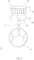
- Fig. 2 shows the detail X Fig. 1 as an enlarged view.
- the ultrasonic vibrator 12 is connected via a twisted wire 13 on the one hand to the core 22 of the CTG cable as a signal conductor and on the other hand via a resistor 14 to the inner shield 24 of the CTG cable.
- the resistor 14 forms part of a block consisting of seven SMD resistors, these seven resistors having a common resistance contact 23 to the shield 24 and a respective free contact.
- One of the two wires 13 coming from the ultrasonic vibrator 12 is connected to a free contact of a resistor 14 and the other of the two wires is connected to the core 22, wherein the signal pad 21 is formed so that all ultrasonic oscillators with this Contact can be connected.
- Fig. 3 shows a schematic representation of a system for imaging a heart, in particular a fetal heart.
- the ultrasonic sensor 10 is connected to a CTG electronics 30 via the CTG cable 20.
- the inner shield 24 of the cable 20 is connected to the ground 32 of the CTG electronics 30.
- the outer shield 26 is connected to the ground 72 of the MRT 70.
- a ferrite core 28 is provided around the CTG cable 20.
- a light field in the front panel can flash in the heart rhythm.
- an opto-coupler 34 can be used, which generates from the signal of the light field an electronic signal representing a heart rhythm.
- a CTG device may be used which provides an electrical output representing a heart rhythm.
- the CTG electronics 30 are integrated with the ultrasonic sensor 10 in the same housing, e.g. in the form of a hand-held device.
- the output of the CTG electronics 30 is wirelessly transmitted to the MRT 70, e.g. via radio signals, infrared signals or acoustic signals.
- the electronic signal of the opto-Koppters 34 is forwarded via a cable 36 to an electronics 40, which converts the signal into an ECG-like, very low-impedance signal.
- an electronics 40 which converts the signal into an ECG-like, very low-impedance signal.
- this converted signal is forwarded to a further electronics 60, which performs a signal level adjustment.
- the resulting processed signal can now be used by the MRT 70 as a control signal (trigger signal) for cardiac imaging.
- MR images of the heart of a patient 80 can be taken, which are always taken at the same time in a cardiac cycle, so that anatomical structures of the heart can be displayed with very high resolution.
- the control signal specifies a progressive point in time relative to the cardiac cycle for the imaging.
- the ultrasonic sensor and the CTG electronics are not provided as separate components, but are in the same housing, for example, the housing 17 of the in Fig. 1 illustrated ultrasonic sensor 10 integrated.
- the ultrasonic sensor and the CTG electronics in a handheld or compact device be summarized.
- the required hardware and software for signal generation and processing could then be implemented in this compact device, which, like the ultrasound sensor, is designed to be MRI-compatible.
- the MRI-compatible compact device can be placed on the patient over the object to be examined, and the measured signals can be transmitted wirelessly to the MRT. It would then be possible to dispense with a special CTG cable, eg with mass discharge at the MRI device.
Landscapes
- Health & Medical Sciences (AREA)
- Life Sciences & Earth Sciences (AREA)
- Physics & Mathematics (AREA)
- Engineering & Computer Science (AREA)
- Nuclear Medicine, Radiotherapy & Molecular Imaging (AREA)
- Biophysics (AREA)
- General Health & Medical Sciences (AREA)
- Radiology & Medical Imaging (AREA)
- Public Health (AREA)
- Heart & Thoracic Surgery (AREA)
- Medical Informatics (AREA)
- Molecular Biology (AREA)
- Surgery (AREA)
- Animal Behavior & Ethology (AREA)
- Pathology (AREA)
- Veterinary Medicine (AREA)
- Biomedical Technology (AREA)
- High Energy & Nuclear Physics (AREA)
- Cardiology (AREA)
- Pulmonology (AREA)
- Physiology (AREA)
- Condensed Matter Physics & Semiconductors (AREA)
- General Physics & Mathematics (AREA)
- Pregnancy & Childbirth (AREA)
- Gynecology & Obstetrics (AREA)
- Power Engineering (AREA)
- Hematology (AREA)
- Signal Processing (AREA)
- Theoretical Computer Science (AREA)
- Computer Networks & Wireless Communication (AREA)
- Ultra Sonic Daignosis Equipment (AREA)
- Magnetic Resonance Imaging Apparatus (AREA)
Description
- Die Erfindung betrifft einen Ultraschallsensor für Kardiotokographie (CTG). Insbesondere betrifft die Erfindung einen CTG-Ultraschallsensor, welcher in einem Magnetresonanztomographen (MRT) verwendbar ist. Ferner betrifft die Erfindung einen Kardiotokographen, d.h. ein CTG-Gerät, mit einem solchen Ultraschallsensor sowie ein System aus einem MRT und einem CTG-Gerät mit einem solchen Ultraschallsensor.
- Da das fetale Herz innerhalb des Uterus liegt, ist dort nicht die Möglichkeit gegeben für eine direkte Erfassung der fetalen Herzfrequenz und damit ist die üblicherweise benötigte Elektrokardiogramm-Steuerung bei Luftanhalten des Patienten während der Messung nicht möglich. Daher ist die Visualisierung von Anomalien des Herzens und großer Gefäße durch MRI (Magnetresonanzbildgebung) nicht erreichbar.
- Für die Untersuchung eines fetalen Herzens mittels MRT beschreiben beispielsweise Manganaro et al., Prenat. Diagn. 2008, 28, 148-156 und Fogel et al., Fetal Diagn. Ther. 2005, 20, 475-480 True fast imaging with steady-state precision (True FISP) und real-time cine-MRsequences zu verwenden, wobei die Durchführung hierbei allerdings ohne eine Steuerung (Triggerung) erfolgt. Nijm et al., J. Magn. Reson. Imaging 2008, 28, 767-772 nutzen selfgating (SG)-Algorithmen zur Synchronisation. Hierbei ist unter anderem das niedrige signalto-noise-Verhältnis limitierend. Yamamura et al., Eur. Radiol. 2009, 19, 2383-90 nutzen ein invasives Triggersystem (Pulse wave triggering). Alle diese Methoden weisen starke Einschränkungen auf, die entweder ihre praktische Anwendung am Menschen unmöglich machen oder es werden keine Bilder ausreichender Qualität geliefert, die die Auswertung von anatomischen Strukturen und funktionalen Informationen erlauben. Michel et al., American Journal of Roentgenologie 2003, 180, 1159-1164, kommen zwar zu dem Schluss, dass die fetale CTG während der Magnetresonanztomographie mit modifiziertem Standard-Equipment machbar ist. Allerdings wird auch festgestellt, dass aus technischen Gründen das CTG-Monitoring während des Aufenthalts des Patienten im Magneten nicht möglich ist (stattdessen wurden Messungen direkt nach dem Verlassen des Magneten getätigt). Die Studie von Michel et al. liefert entsprechend keine MRT-Bilder des fetalen Herzens.
- Die
WO 95/02361 - Die Verwendung von ultraschallbasierten Sensoren zur Triggerung der Bildgebung eines MRT-Systems wird auch in der
US 2005/0272995 A1 beschrieben. In diesem Fall wird ein Ultraschallschwinger beispielsweise auf dem Brustkorb des Patienten angeordnet, um Herzbewegungen oder den Blutfluss zu erfassen. - Die
WO 2004/026135 A1 beschreibt Verdrahtungsanordnungen für Sensorkatheter, bei welchen verdrillte Leitungspaare zum Einsatz kommen, um elektromagnetische Interferenz unter verschiedenen Leitungen zu vermindern. - Die
WO 2007/059474 A2 bezieht sich auf die Reduzierung von Störungen in einem Bildgebungskathetersystem, bei welchem Ferrit-Kerne zur Vermeidung von Signalverzerrungen eingesetzt werden. - Die
WO 2008/097487 A2 beschreibt ein Ultraschallbildgebungssystem, bei welchem eine Basiseinheit und ein Sensor vorgesehen sind, welche drahtlos kommunizieren können. Insbesondere ist vorgesehen, dass über Ultraschallschwinger aufgenommene Signale an die Basiseinheit übertragen werden, wo eine weitere Auswertung zur Bildgebung erfolgt. - Das Problem der störenden Wechselwirkung zwischen dem CTG-Gerät und dem MRT ist ein seit Jahren ungelöstes Problem.
- Es ist eine Aufgabe der Erfindung, einen Ultraschallsensor für ein CTG-Gerät bereitzustellen, welcher geeignet ist, ein Steuersignal für eine Untersuchung eines Patienten in einem MRT bereitzustellen. Diese und weitere Aufgaben werden durch die jeweiligen Gegenstände der unabhängigen Ansprüche gelöst. Weitere bevorzugte Ausführungsformen sind in den abhängigen Ansprüchen beschrieben.
- Gemäß einem Ausführungsbeispiel der Erfindung weist ein Ultraschallsensor für ein Cardiotokographiegerät (CTG-Gerät) somit zumindest einen Ultraschallschwinger, zumindest einen Widerstand, der mit dem Ultraschallschwinger verbunden ist, und ein Gehäuse auf. In dem Gehäuse sind der Ultraschallschwinger und der Widerstand untergebracht. Der Ultraschallsensor ist aus Materialien hergestellt, die nicht ferromagnetisch sind, so dass sich der Ultraschallsensor neutral gegenüber einem äußeren Magnetfeld verhält. Speziell bedeutet dies, dass der Widerstand aus einem nicht-ferromagnetischen Material besteht und dass der Widerstand mittels eines nicht-ferromagnetischen Drahtes mit dem Ultraschallschwinger verbunden ist.
- Der Ultraschallschwinger ist über verdrillte Kabel mit dem Widerstand verbunden. Genauer gesagt kann ein erster Pol des Ultraschallschwingers mit einem Signal-Leiter einer CTG-Elektronik des CTG-Geräts verbunden sein und ein zweiter Pol des Ultraschallschwingers ist über den Widerstand mit einer Masse der CTG-Elektronik verbunden, wobei die beiden Kabel miteinander verdrillt sind.
- Selbst wenn der Ultraschallsensor Signale aufnimmt und selbst innerhalb des Magnetfelds eines MRT angeordnet ist, wird das Magnetfeld des MRT nahezu nicht gestört oder beeinflusst, so dass eine Bildgebung durch das MRT nahezu ohne Artefakte und in der gewünschten Auflösung möglich ist. Beispielsweise kann der Ultraschallsensor die Bildgebung in seiner unmittelbaren Nähe beeinflussen, ohne dass diese Beeinflussung den Bereich von Interesse (zum Beispiel das fetale Herz) betrifft. Weiterhin werden Störungen des Betriebs des Ultraschallsensors durch das Magnetfeld des MRT und die von dem MRT ausgestrahlten Hochfrequenzimpulse vermieden. Somit kann der Ultraschallsensor auch während laufender Messungen im Bildgebungsbereich des MRT betrieben werden. Es ist so insbesondere möglich dopplersonografische Signale im MRT während laufender MRT-Messungen aufzunehmen.
- Der Ultraschallsensor ist auf der einen Seite neutral gegenüber dem äußeren Magnetfeld, d. h. er erzeugt keine Störungen im Magnetfeld. Auf der anderen Seite ist der Ultraschallsensor durch die Verbindung über verdrillte Kabel aber auch gegen Störungen des weitaus stärkeren äußeren Magnetfeldes abgeschirmt. Diese gute Abschirmung erlaubt eine vollständige Funktionsfähigkeit des Ultraschallsensors sowohl im statischen Magnetfeld als auch während der laufenden MRT-Messungen mit Einstrahlung von Hochfrequenzimpulsen.
- 'Neutral' im Sinne der Erfindung umfasst, dass ein mögliches störendes Feld lediglich auftritt in einem Abstand von bis zu 30 mm, gemessen senkrecht zur Oberfläche von beispielsweise dem Gehäuse des Ultraschallsensors. Bevorzugt tritt ein störendes Feld nur bis zu einem Abstand von 20 mm auf. Idealerweise wird ein äußeres Magnetfeld nur im Bereich eines Abstandes von 0 bis 12 mm gestört oder beeinflusst.
- Gemäß einem Ausführungsbeispiel der Erfindung weist der Ultraschallsensor keine Platine auf, über welche der zumindest eine Ultraschallschwinger und der zumindest eine Widerstand miteinander verbunden sind. Auf diese Weise kann eine weitere störende Struktur vermieden werden.
- Gemäß einem Ausführungsbeispiel der Erfindung weist der Ultraschallsensor sieben Ultraschallschwinger und sieben Widerstände auf, welche beispielsweise über eine freie Bedrahtung, vorzugsweise mit paarweise verdrillten Kabeln, miteinander verbunden sind.
- Die Widerstände wie auch die Bedrahtung können aus einem oder mehreren nicht-ferromagnetischen Materialien bestehen. Insbesondere eisen- und nickelhaltige Materialien können auf diese Weise vermieden werden.
- Gemäß einem weiteren Ausführungsbeispiel der Erfindung können der Ultraschallschwinger, der Widerstand sowie die verdrillte Bedrahtung auf einer nicht-ferromagnetischen Platine angeordnet sein, die entsprechend frei von Eisen oder Nickel etc. sein sollte. Über eine derartige Platine kann eine automatisierbare Herstellung erleichtert werden. Außerdem kann eine zuverlässige Anordnung von mehreren Elementen gewährleistet werden.
- Als Abschirmung kann das Gehäuse des Ultraschallsensors von außen komplett metallisiert sein, beispielsweise mit Leitsilber behandelt sein.
- Erfindungsgemäß ist eine kabellose Übertragung vorgesehen. Insbesondere ist die CTG-Elektronik in dem Gehäuse des Ultraschallsensors integriert, und ein einen Herzrhythmus repräsentierendes Ausgangssignal der CTG-Elektronik kann mittels einer Sendeeinheit kabellos an das MRT übertragen werden, von welchem es beispielsweise als Triggersignal für die Herzbildgebung verwendet werden kann. Vorzugsweise ist auch die CTG-Elektronik durch nicht-ferromagnetische Materialien realisiert und verwendet eine Bedrahtung mit paarweise verdrillten Kabeln, um Störungen durch dynamische elektrische und magnetische Felder im Betrieb des MRT zu vermeiden. Weiterhin kann die CTG-Elektronik in diesem Fall auch Signalfilter zur Unterdrückung von Frequenzen der von dem MRT eingestrahlten Hochfrequenzsignale umfassen.
- Jede der oben beschriebenen einzelnen Maßnahmen der Abschirmung sorgt für eine verbesserte Kompatibilität des Ultraschallsensors mit dem MRT.
- Gemäß einem weiteren Ausführungsbeispiel der Erfindung kann ein Ultraschallsensor gemäß einem oder mehreren der genannten Ausführungsbeispiele zusammen mit einem MRT verwendet werden, wobei der Ultraschallsensor innerhalb des Magnetfeldes des MRT angeordnet ist und wobei die Bildgebung des MRT durch das Ausgangssignal der CTG-Elektronik gesteuert (getriggert) wird.
- Gemäß einem weiteren Ausführungsbeispiel der Erfindung wird ein System zur Bildgebung eines Herzens, insbesondere eines fetalen Herzens, bereitgestellt, welches den Ultraschallsensor, ein CTG-Gerät mit dem ultraschallsensor, sowie ein MRT aufweist, wobei die CTG-Elektronik angepasst ist, auf der Basis einer Schwingungserfassung des Ultraschallschwingers das Ausgangssignal zur Steuerung der Bildgebung des MRT bereitzustellen.
- Hierfür kann die CTG-Elektronik mehrfach spezielle Impulsketten (Bursts) an den Sensor senden, die dieser als Ultraschall abstrahlt. Dann kann jeweils das Echo der Bursts empfangen und von der CTG-Elektronik interpretiert werden, wobei die Interpretation bei dieser Anwendung auf Laufzeitunterschieden beruhen kann (Doppler-Effekt), aus denen dann die Herzfrequenz berechnet werden kann.
- Die oben beschriebenen Aspekte und weitere Aspekte, Merkmale und Vorteile der Erfindung können ebenfalls aus den Beispielen der Ausführungsformen entnommen werden, welche im Folgenden unter Bezugnahme der anhängenden Zeichnungen beschrieben werden.
-
-
Fig. 1 ist eine schematische Darstellung eines Ultraschallsensors. -
Fig. 2 ist eine vergrößerte Darstellung des Details X ausFig. 1 . -
Fig. 3 ist eine schematische Darstellung eines Systems mit CTG und MRT. -
Fig. 1 zeigt eine schematische Darstellung eines Ultraschallsensors 10 mit einem CTG-Kabel 20. Der Ultraschallsensor liefert ein Triggersignal zur verbesserten Bildgebung eines MRT. - Der Ultraschallsensor 10 weist ein Gehäuse 17 auf, in welchem Ultraschallschwinger 12 und Widerstände 14 angeordnet sind. In
Fig. 1 sind exemplarisch ein Ultraschallschwinger 12 und ein Widerstand 14 über eine verdrillte Bedrahtung 13 miteinander verbunden (Detail X). Der Übersicht wegen ist auf eine Darstellung der verdrillten Bedrahtungen zwischen den anderen Ultraschallschwingern und den korrespondierenden Widerständen verzichtet worden. - Ferner ist innerhalb des Gehäuses 17 eine Abschirmfolie 16 vorgesehen. Die Abschirmfolie 16 ist in
Fig. 1 lediglich schematisch angedeutet. Es wird angemerkt, dass die Abschirmfolie derart ausgebildet sein kann, dass sie alle Ultraschallschwinger 12 und auch die Widerstände 14 sowie die Bedrahtungen 13 innerhalb des Gehäuses 17 abdeckt. - Das Äußere des Gehäuses 17 ist komplett metallisiert, beispielsweise mit Leitsilber 18 behandelt. Auch hier ist das Leitsilber 18 nur teilweise und schematisch in
Fig. 1 angedeutet. Es wird angemerkt, dass das Leitsilber 18 die komplette äußere Oberfläche des Gehäuses 17 abdecken kann. - Von dem Gehäuse 17 des Ultraschallsensors 10 führt ein CTG-Kabel 20 weg. Das CTG-Kabel 20 besteht aus einem Kern 22, einer inneren Abschirmung 24 und einer äußeren Abschirmung 26. Der innere Kern 22 ist innerhalb des Ultraschallsensors mit der Bedrahtung 13 der Widerstände 14 und der Ultraschallschwinger 12 verbunden, so dass ein Signal von den Ultraschallschwingern aus dem Ultraschallsensor zu einer CTG- Elektronik abgeleitet werden kann. Der Kern des CTG-Kabels 20 kann zweipolig ausgeführt sein.
- Die innere Abschirmung 24 führt auf der Seite des Ultraschallsensors bis in das Gehäuse 17 hinein und ist in dem Gehäuse mit der Abschirmfolie 16 verbunden. Die innere Abschirmung 24 ist über die gesamte Länge des Kabels 20 vorgesehen und ist an ihrem anderen Ende mit der Masse der CTG-Elektronik verbunden. Auf diese Weise ist die Abschirmfolie in dem Gehäuse 17 des Ultraschallsensors mit der Masse der CTG-Elektronik verbunden.
- Die äußere Abschirmung 26 des CTG-Kabels 20 ist nicht über die gesamte Länge des CTG-Kabels ausgebildet. Beispielsweise können 1,5 m des CTG-Kabels ausgehend vom Ultraschallsensor 10 mit der äußeren Abschirmung 26 ausgebildet sein. Diese zusätzliche äußere Abschirmung ist mit der Masse des MRT verbunden und an dem Ultraschallsensor mit dem Leitsilber 18 außen an dem Gehäuse 17 verbunden.
-
Fig. 2 zeigt das Detail X ausFig. 1 als vergrößerte Darstellung. Der Ultraschallschwinger 12 ist über eine verdrillte Bedrahtung 13 einerseits mit dem Kern 22 des CTG-Kabels als Signal-Leiter verbunden und andererseits über einen Widerstand 14 mit der inneren Abschirmung 24 des CTG-Kabels. Der Widerstand 14 bildet einen Teil eines Blocks, der aus sieben SMD-Widerständen besteht, wobei diese sieben Widerstände einen gemeinsamen Widerstand-Kontakt 23 zu der Abschirmung 24 haben und einen jeweiligen freien Kontakt. - Einer der zwei Drähte 13, die von dem Ultraschallschwinger 12 kommen, ist mit einem freien Kontakt eines Widerstandes 14 verbunden und der andere der zwei Drähte ist mit dem Kern 22 verbunden, wobei die Signal-Kontaktstelle 21 so ausgebildet ist, dass alle Ultraschallschwinger mit dieser Kontaktstelle verbunden sein können.
-
Fig. 3 zeigt eine schematische Darstellung eines Systems zur Bildgebung eines Herzens, insbesondere eines fetalen Herzens. Der Ultraschallsensor 10 ist über das CTG-Kabel 20 mit einer CTG-Elektronik 30 verbunden. Auch hier inFig. 3 ist angedeutet, dass die innere Abschirmung 24 des Kabels 20 mit der Masse 32 der CTG-Elektronik 30 verbunden ist. Ferner ist dargestellt, dass die äußere Abschirmung 26 mit der Masse 72 des MRT 70 verbunden ist. Zusätzlich ist dargestellt, dass um das CTG-Kabel 20 herum ein Ferritkern 28 vorgesehen ist. - Bei der CTG-Elektronik 30 kann, wie bei einem handelsüblichen CTG-Gerät, im Betrieb ein Leuchtfeld in der Frontplatte im Herzrhythmus blinken. Um dieses blinkende Leuchtfeld zu nutzen, kann ein Opto-Koppler 34 eingesetzt werden, der aus dem Signal des Leuchtfeldes ein elektronisches Signal erzeugt, welches einen Herzrhythmus repräsentiert.
- Alternativ kann auch ein CTG-Gerät verwendet werden, welches ein elektrisches Ausgangssignal liefert, das einen Herzrhythmus repräsentiert. Die CTG-Elektronik 30 ist mit dem Ultraschallsensor 10 in demselben Gehäuse integriert, z.B. in Form eines Handgerätes. Das Ausgangssignal der CTG-Elektronik 30 wird kabellos an das MRT 70 übertragen, z.B. über Funksignale, Infrarotsignale oder akustische Signale.
- Bei dem in
Fig. 3 dargestellten Beispiel wird das elektronische Signal des Opto-Koppters 34 überein Kabel 36 zu einer Elektronik 40 weitergeleitet, welche das Signal in ein EKG-ähnliches, sehr niederohmiges Signal wandelt. Über ein Koaxialkabel 50, an welchem ein weiterer Ferritkern 52 vorgesehen sein kann, wird dieses gewandelte Signal an eine weitere Elektronik 60 weitergeleitet, welche eine Signalpegel-Anpassung vornimmt. - Das resultierende, aufbereitete Signal kann nun vom MRT 70 als Steuersignal (Triggersignal) für die Herzbildgebung verwendet werden. Auf diese Weise können MRT-Darstellungen des Herzens eines Patienten 80 durchgeführt werden, die immer zum gleichen Zeitpunkt in einem Herzzyklus aufgenommen sind, so dass anatomische Strukturen des Herzens mit sehr hoher Auflösung dargestellt werden können. Dies ist mittels des erfindungsgemässen Systems insbesondere auch für ein Herz eines ungeborenen Kindes im Mutterleib möglich. Es wird angemerkt, dass auch der Ablauf der Herzbewegungen darstellbar ist, wobei hierfür das Steuersignal einen fortschreitenden Zeitpunkt relativ zum Herzzyklus für die Bildgebung vorgibt.
- Es versteht sich, dass bei den dargestellten Beispielen verschiedene Modifikationen möglich sind. Der Ultraschallsensor und die CTG-Elektronik sind nicht als separate Komponenten vorgesehen, sondern sind in demselben Gehäuse, z.B. dem Gehäuse 17 des in
Fig. 1 dargestellten Ultraschallsensors 10. integriert. Beispielsweise können der Ultraschallsensor und die CTG-Elektronik in einem Handgerät bzw. Kompaktgerät zusammengefasst sein. Die erforderliche Hardware und Software zur Signalgenerierung und -aufbereitung könnte dann in diesem Kompaktgerät implementiert sein, welches wie der Ultraschallsensor MRT-kompatibel ausgestaltet ist. Das MRT-kompatible Kompaktgerät kann beispielsweise auf dem Patienten über dem zu untersuchenden Objekt platziert werden, und die gemessenen Signale können kabellos an das MRT weitergeleitet werden. Auf ein spezielles CTG-Kabel, z.B. mit Masseableitung am MRT-Gerät, könnte dann verzichtet werden. - Weiterhin versteht es sich, dass die hierin beschriebenen Konzepte in einer Vielzahl von Einsatzbereichen Vorteile bieten. Beispiele von solchen Einsatzbereichen sind:
- Erzeugung eines Triggersignals, welches die Herzfrequenz von Erwachsenen, Kindern und intrauterin von Feten repräsentiert. Dieses Triggersignal kann zur Herz- und Gefäßbildgebung im MRT verwendet werden. Die dadurch ermöglichte getriggerte kardiovaskuläre fetale MRT-Bildgebung liefert wertvolle Informationen für das weitere therapeutische Vorgehen bei fetalen Fehlbildungen. Das MRT erlaubt eine genaue anatomische Darstellung des Herzens (inklusive Foramen ovale) und zusätzlich funktionelle Aussagen wie z.B. die Ejektionsfraktion. So kann bereits intrauterin das Ausmaß einer kardialen Fehlbildung für die Planung nachfolgender chirurgischer Eingriffe bestimmt werden. Abgesehen vom Einsatz in der Pränataldiagnostik kann das System auch die EKG-Steuerung bei der Untersuchung von Erwachsenen ersetzen. Es kann dann für die Untersuchung von Erwachsenen vorteilhaft genutzt werden, wenn die üblichen EKG-Elektroden grundsätzlich Mehraufwand (Rasieren der Brust) und Probleme (Abfallen der selbstklebenden EKG-Elektroden) verursachen und in manchen Fällen gar nicht eingesetzt werden können (z.B. bei Patienten mit Pleuraergüssen, Perikardergüssen, Adipositas).
- Monitoring der Herzfrequenz von Feten, Kindern, Erwachsenen und damit einer Vitalfunktion während der MRT-Messung: Neben der cardialen Triggerung eignet sich das hierin beschriebene MRT kompatible CTG-Gerät auch zum kontinuierlichen Monitoring von Feten während der MRT-Untersuchung. Dies ist von klinischer Bedeutung, da häufig Risikoschwangerschaften im MRT untersucht werden. Natürlich kann ein solches Monitoring auch bei Kindern oder Erwachsenen erfolgen.
-
- 10
- Ultraschallsensor
- 12
- Ultraschallschwinger
- 13
- Bedrahtung
- 14
- Widerstand
- 16
- Abschirmfolie
- 17
- Gehäuse
- 18
- Leitsilber
- 20
- CTG-Kabel
- 21
- Signal-Kontaktstelle
- 22
- Kabel-Kern
- 23
- Widerstand-Kontakt
- 24
- Innere Abschirmung
- 26
- Äußere Abschirmung
- 28
- Ferritkern
- 30
- CTG-Elektronik
- 32
- CTG-Masse
- 34
- Opto-Koppler
- 36
- Kabel
- 40
- Signalwandler
- 50
- Koaxialkabel
- 52
- Ferritkern
- 60
- Signalpegelanpassung
- 70
- MRT
- 72
- MRT-Masse
- 80
- Patient
Claims (7)
- Ultraschallsensor (10) für ein Kardiotokographiegerät, aufweisend:einen Ultraschallschwinger (12),einen Widerstand (14), undein Gehäuse (17), in welchem der Ultraschallschwinger und der Widerstand untergebracht sind,wobei der Ultraschallsensor (10) aus einem nicht-ferromagnetischen Material hergestellt ist, so dass er sich neutral gegenüber einem äußeren Magnetfeld verhält, wobei der Widerstand mit dem Ultraschallschwinger über verdrillte Kabel verbunden ist,eine Kardiotokographie-Elektronik (30) in dem Gehäuse (17) untergebracht ist, wobei die Kardiotokographie-Elektronik ein Ausgangssignal liefert, welches einen Herzrhythmus repräsentiert, undder Ultraschallsensor (10) eine Sendeeinheit zur kabellosen Übertragung des Ausgangssignals an einen Magnetresonanztomographen (70) aufweist.
- Verwendung eines Ultraschallsensors (10) gemäß Anspruch 1 mit einem Magnetresonanztomographen (70), wobei der Ultraschallsensor (10) innerhalb des Magnetfeldes des Magnetresonanztomographen (70) angeordnet ist, und
wobei die Bildgebung des Magnetresonanztomographen durch das Ausgangssignal der Kardiotokographie-Elektronik (30) gesteuert wird. - Verwendung gemäß Anspruch 2,
wobei das Ausgangssignal einen Herzrhythmus eines Erwachsenen, eines Kindes, oder eines Feten im Mutterleib repräsentiert. - Verwendung gemäß Anspruch 2,
wobei der Magnetresonanztomograph (70) zur Herz- oder Gefäßbildgebung eingesetzt wird. - Kardiotokographiegerät mit
einem Ultraschallsensor (10) gemäß Anspruch 1. - Kardiotokographiegerät gemäß Anspruch 5,
wobei der Ultraschallsensor (10) in einem Magnetfeld des Magnetresonanztomographen (70) anordenbar ist, wobei die Anwesenheit des Ultraschallsensors (10) die Bildgebung des Magnetresonanztomographen (70) nicht störend beeinflusst, und
wobei die Bildgebung des Magnetresonanztomographen (70) durch das Ausgangssignal steuerbar ist, welches von der Kardiotokographie-Elektronik (30) erzeugt wird. - System zur Bildgebung eines Herzens, aufweisend
einen Ultraschallsensor (10) gemäß Anspruch 1, und
einen Magnetresonanztomographen (70),
wobei die Kardiotokographie-Elektronik (30) angepasst ist, auf der Basis einer Schwingungserfassung des Ultraschallschwingers des Ultraschallsensors (10) das Ausgangssignal zur Steuerung der Bildgebung des Magnetresonanztomographen (70) bereitzustellen.
Applications Claiming Priority (2)
| Application Number | Priority Date | Filing Date | Title |
|---|---|---|---|
| DE102010025857A DE102010025857B4 (de) | 2010-07-02 | 2010-07-02 | Ultraschallsensor, Kardiotokograph und System zur Bildgebung eines Herzens |
| PCT/EP2011/061131 WO2012001150A1 (de) | 2010-07-02 | 2011-07-01 | Ultraschallsensor für einen kardiotokographen |
Publications (2)
| Publication Number | Publication Date |
|---|---|
| EP2587993A1 EP2587993A1 (de) | 2013-05-08 |
| EP2587993B1 true EP2587993B1 (de) | 2017-10-11 |
Family
ID=44509225
Family Applications (1)
| Application Number | Title | Priority Date | Filing Date |
|---|---|---|---|
| EP11728854.8A Not-in-force EP2587993B1 (de) | 2010-07-02 | 2011-07-01 | Ultraschallsensor für einen kardiotokographen |
Country Status (4)
| Country | Link |
|---|---|
| US (1) | US9622723B2 (de) |
| EP (1) | EP2587993B1 (de) |
| DE (1) | DE102010025857B4 (de) |
| WO (1) | WO2012001150A1 (de) |
Families Citing this family (2)
| Publication number | Priority date | Publication date | Assignee | Title |
|---|---|---|---|---|
| DE102012005895B3 (de) * | 2012-03-23 | 2013-07-18 | Fraunhofer-Gesellschaft zur Förderung der angewandten Forschung e.V. | Ultraschall-Messeinrichtung, Untersuchungsgerät und Verfahren zu deren Betrieb |
| EP3181055A1 (de) * | 2015-12-16 | 2017-06-21 | Universitätsklinikum Hamburg-Eppendorf | Ultraschallvorrichtung zur detektion des herzschlags eines patienten |
Family Cites Families (9)
| Publication number | Priority date | Publication date | Assignee | Title |
|---|---|---|---|---|
| US3989034A (en) * | 1975-04-24 | 1976-11-02 | Corometrics Medical Systems, Inc. | Apparatus and method for signaling fetal distress and uterine contraction monitor for use therein |
| WO1993008534A1 (en) * | 1991-10-24 | 1993-04-29 | Hewlett-Packard Gmbh | Apparatus and method for evaluating the fetal condition |
| WO1995002361A1 (en) | 1993-07-15 | 1995-01-26 | Zimmer Stevan D | Doppler ultrasound trigger for use with mr |
| DE19635593C1 (de) * | 1996-09-02 | 1998-04-23 | Siemens Ag | Ultraschallwandler für den diagnostischen und therapeutischen Einsatz |
| US6937883B2 (en) * | 2000-03-08 | 2005-08-30 | Martin R. Prince | System and method for generating gating signals for a magnetic resonance imaging system |
| JP2003135458A (ja) * | 2001-10-30 | 2003-05-13 | Hitachi Ltd | 超音波探触子、超音波撮像装置及び撮像方法 |
| AU2003270831A1 (en) * | 2002-09-23 | 2004-04-08 | Volcano Corporation | Sensor catheter having reduced cross-talk wiring arrangements |
| US7887488B2 (en) * | 2005-11-12 | 2011-02-15 | Scimed Life Systems, Inc. | Systems and methods for reducing noise in an imaging catheter system |
| US9706976B2 (en) * | 2007-02-08 | 2017-07-18 | Siemens Medical Solutions Usa, Inc. | Ultrasound imaging systems and methods of performing ultrasound procedures |
-
2010
- 2010-07-02 DE DE102010025857A patent/DE102010025857B4/de not_active Expired - Fee Related
-
2011
- 2011-07-01 WO PCT/EP2011/061131 patent/WO2012001150A1/de not_active Ceased
- 2011-07-01 US US13/807,944 patent/US9622723B2/en not_active Expired - Fee Related
- 2011-07-01 EP EP11728854.8A patent/EP2587993B1/de not_active Not-in-force
Non-Patent Citations (1)
| Title |
|---|
| None * |
Also Published As
| Publication number | Publication date |
|---|---|
| DE102010025857A1 (de) | 2012-01-05 |
| US9622723B2 (en) | 2017-04-18 |
| EP2587993A1 (de) | 2013-05-08 |
| US20130178732A1 (en) | 2013-07-11 |
| DE102010025857B4 (de) | 2013-01-17 |
| WO2012001150A1 (de) | 2012-01-05 |
Similar Documents
| Publication | Publication Date | Title |
|---|---|---|
| DE102015203385B4 (de) | Verfahren zur Erzeugung einer Bewegungsinformation zu einem zumindest teilweise bewegten Untersuchungsbereich sowie Magnetresonanzanlage und Hybrid-Bildgebungsmodalität | |
| DE69609529T2 (de) | Digitales dreidimensionales ultraschall-folgesystem | |
| DE68926415T2 (de) | Ultraschall bildsonde | |
| EP2942008B1 (de) | Magnetresonanzvorrichtung mit einer bewegungserfassungseinheit sowie ein verfahren zu einer erfassung einer bewegung eines patienten während einer magnetresonanzuntersuchung | |
| DE69232490T2 (de) | Vorrichtung zur gewebe-untersuchung unter verwendung von ultraschall-kontrastmittel | |
| DE69226371T2 (de) | Transportkatheter und ultraschallsonde zur verwendung mit demselben | |
| DE19827245A1 (de) | Biomagnetfeld-Messvorrichtung | |
| DE3702355C2 (de) | ||
| DE19909066A1 (de) | Verfahren und Vorrichtung zum Bestimmen der Lage eines Katheters innerhalb des Körpers eines Lebewesens | |
| DE102010061261A1 (de) | Manuelle Ultraschallleistungssteuerung zur Überwachung der fetalen Herzfrequenz in Abhängigkeit von der Größe der Patientin | |
| Yamamura et al. | Cardiac MRI of the fetal heart using a novel triggering method: initial results in an animal model | |
| EP2946730A1 (de) | Verfahren zur vermessung des atemvorgangs eines patienten während einer magnetresonanzuntersuchung, messanordnung und magnetresonanzeinrichtung | |
| DE102010023845A1 (de) | MR-Spule mit beweglichen Antennenelementen | |
| WO1995002361A1 (en) | Doppler ultrasound trigger for use with mr | |
| DE102007027366A1 (de) | Bildgebungsvorrichtung und Bildgebungsverfahren | |
| DE102010025919A1 (de) | Spule; D-Form | |
| DE102008019862A1 (de) | Magnetresonanzgerät und Verfahren zum Betrieb eines Magnetresonanzgeräts | |
| DE102006058316B4 (de) | Verfahren zur Aufnahme von Bilddaten einer Gefäßwand und Magnet-Resonanz-Gerät hierzu | |
| DE102014201585A1 (de) | Einrichtung zur Positionierung eines Untersuchungsobjekts, Verfahren zur Erstellung eines Bildes mit einem bildgebenden System und bildgebendes System | |
| DE102010025857B4 (de) | Ultraschallsensor, Kardiotokograph und System zur Bildgebung eines Herzens | |
| Strassle Rojas et al. | Ultrasound‐gated computed tomography coronary angiography: Development of ultrasound transducers with improved computed tomography compatibility | |
| DE3886630T2 (de) | Ultraschall-Abbildungsgerät. | |
| DE102009040198A1 (de) | Radar Sensorik zur Überwachung von Flüssigkeitsansammlungen im menschlichen Körper | |
| JP3967429B2 (ja) | 超音波診断装置 | |
| DE102014208650A1 (de) | Verfahren zur Ermittlung eines Synchronisationssignals für eine Bildgebungsvorrichtung |
Legal Events
| Date | Code | Title | Description |
|---|---|---|---|
| PUAI | Public reference made under article 153(3) epc to a published international application that has entered the european phase |
Free format text: ORIGINAL CODE: 0009012 |
|
| 17P | Request for examination filed |
Effective date: 20130131 |
|
| AK | Designated contracting states |
Kind code of ref document: A1 Designated state(s): AL AT BE BG CH CY CZ DE DK EE ES FI FR GB GR HR HU IE IS IT LI LT LU LV MC MK MT NL NO PL PT RO RS SE SI SK SM TR |
|
| RIN1 | Information on inventor provided before grant (corrected) |
Inventor name: WEDEGAERTNER, ULRIKE Inventor name: VALLET, KLAUS Inventor name: YAMAMURA, JIN |
|
| DAX | Request for extension of the european patent (deleted) | ||
| REG | Reference to a national code |
Ref country code: DE Ref legal event code: R079 Ref document number: 502011013118 Country of ref document: DE Free format text: PREVIOUS MAIN CLASS: A61B0005030000 Ipc: A61B0008000000 |
|
| RIC1 | Information provided on ipc code assigned before grant |
Ipc: A61B 5/03 20060101ALI20161223BHEP Ipc: A61B 8/02 20060101ALI20161223BHEP Ipc: G01R 33/567 20060101ALI20161223BHEP Ipc: A61B 8/00 20060101AFI20161223BHEP Ipc: G01R 33/48 20060101ALI20161223BHEP Ipc: A61B 5/055 20060101ALI20161223BHEP Ipc: A61B 8/08 20060101ALI20161223BHEP |
|
| GRAP | Despatch of communication of intention to grant a patent |
Free format text: ORIGINAL CODE: EPIDOSNIGR1 |
|
| INTG | Intention to grant announced |
Effective date: 20170323 |
|
| GRAS | Grant fee paid |
Free format text: ORIGINAL CODE: EPIDOSNIGR3 |
|
| GRAJ | Information related to disapproval of communication of intention to grant by the applicant or resumption of examination proceedings by the epo deleted |
Free format text: ORIGINAL CODE: EPIDOSDIGR1 |
|
| GRAL | Information related to payment of fee for publishing/printing deleted |
Free format text: ORIGINAL CODE: EPIDOSDIGR3 |
|
| RIN1 | Information on inventor provided before grant (corrected) |
Inventor name: YAMAMURA, JIN Inventor name: WEDEGAERTNER, ULRIKE Inventor name: VALETT, KLAUS |
|
| INTC | Intention to grant announced (deleted) | ||
| GRAR | Information related to intention to grant a patent recorded |
Free format text: ORIGINAL CODE: EPIDOSNIGR71 |
|
| GRAA | (expected) grant |
Free format text: ORIGINAL CODE: 0009210 |
|
| AK | Designated contracting states |
Kind code of ref document: B1 Designated state(s): AL AT BE BG CH CY CZ DE DK EE ES FI FR GB GR HR HU IE IS IT LI LT LU LV MC MK MT NL NO PL PT RO RS SE SI SK SM TR |
|
| INTG | Intention to grant announced |
Effective date: 20170905 |
|
| REG | Reference to a national code |
Ref country code: GB Ref legal event code: FG4D Free format text: NOT ENGLISH |
|
| REG | Reference to a national code |
Ref country code: CH Ref legal event code: EP |
|
| REG | Reference to a national code |
Ref country code: IE Ref legal event code: FG4D Free format text: LANGUAGE OF EP DOCUMENT: GERMAN |
|
| REG | Reference to a national code |
Ref country code: AT Ref legal event code: REF Ref document number: 935308 Country of ref document: AT Kind code of ref document: T Effective date: 20171115 |
|
| REG | Reference to a national code |
Ref country code: DE Ref legal event code: R096 Ref document number: 502011013118 Country of ref document: DE |
|
| REG | Reference to a national code |
Ref country code: NL Ref legal event code: MP Effective date: 20171011 |
|
| REG | Reference to a national code |
Ref country code: LT Ref legal event code: MG4D |
|
| PG25 | Lapsed in a contracting state [announced via postgrant information from national office to epo] |
Ref country code: NL Free format text: LAPSE BECAUSE OF FAILURE TO SUBMIT A TRANSLATION OF THE DESCRIPTION OR TO PAY THE FEE WITHIN THE PRESCRIBED TIME-LIMIT Effective date: 20171011 |
|
| PG25 | Lapsed in a contracting state [announced via postgrant information from national office to epo] |
Ref country code: SE Free format text: LAPSE BECAUSE OF FAILURE TO SUBMIT A TRANSLATION OF THE DESCRIPTION OR TO PAY THE FEE WITHIN THE PRESCRIBED TIME-LIMIT Effective date: 20171011 Ref country code: ES Free format text: LAPSE BECAUSE OF FAILURE TO SUBMIT A TRANSLATION OF THE DESCRIPTION OR TO PAY THE FEE WITHIN THE PRESCRIBED TIME-LIMIT Effective date: 20171011 Ref country code: LT Free format text: LAPSE BECAUSE OF FAILURE TO SUBMIT A TRANSLATION OF THE DESCRIPTION OR TO PAY THE FEE WITHIN THE PRESCRIBED TIME-LIMIT Effective date: 20171011 Ref country code: NO Free format text: LAPSE BECAUSE OF FAILURE TO SUBMIT A TRANSLATION OF THE DESCRIPTION OR TO PAY THE FEE WITHIN THE PRESCRIBED TIME-LIMIT Effective date: 20180111 Ref country code: FI Free format text: LAPSE BECAUSE OF FAILURE TO SUBMIT A TRANSLATION OF THE DESCRIPTION OR TO PAY THE FEE WITHIN THE PRESCRIBED TIME-LIMIT Effective date: 20171011 |
|
| PG25 | Lapsed in a contracting state [announced via postgrant information from national office to epo] |
Ref country code: RS Free format text: LAPSE BECAUSE OF FAILURE TO SUBMIT A TRANSLATION OF THE DESCRIPTION OR TO PAY THE FEE WITHIN THE PRESCRIBED TIME-LIMIT Effective date: 20171011 Ref country code: BG Free format text: LAPSE BECAUSE OF FAILURE TO SUBMIT A TRANSLATION OF THE DESCRIPTION OR TO PAY THE FEE WITHIN THE PRESCRIBED TIME-LIMIT Effective date: 20180111 Ref country code: GR Free format text: LAPSE BECAUSE OF FAILURE TO SUBMIT A TRANSLATION OF THE DESCRIPTION OR TO PAY THE FEE WITHIN THE PRESCRIBED TIME-LIMIT Effective date: 20180112 Ref country code: LV Free format text: LAPSE BECAUSE OF FAILURE TO SUBMIT A TRANSLATION OF THE DESCRIPTION OR TO PAY THE FEE WITHIN THE PRESCRIBED TIME-LIMIT Effective date: 20171011 Ref country code: IS Free format text: LAPSE BECAUSE OF FAILURE TO SUBMIT A TRANSLATION OF THE DESCRIPTION OR TO PAY THE FEE WITHIN THE PRESCRIBED TIME-LIMIT Effective date: 20180211 Ref country code: HR Free format text: LAPSE BECAUSE OF FAILURE TO SUBMIT A TRANSLATION OF THE DESCRIPTION OR TO PAY THE FEE WITHIN THE PRESCRIBED TIME-LIMIT Effective date: 20171011 |
|
| REG | Reference to a national code |
Ref country code: DE Ref legal event code: R097 Ref document number: 502011013118 Country of ref document: DE |
|
| REG | Reference to a national code |
Ref country code: FR Ref legal event code: PLFP Year of fee payment: 8 |
|
| PG25 | Lapsed in a contracting state [announced via postgrant information from national office to epo] |
Ref country code: DK Free format text: LAPSE BECAUSE OF FAILURE TO SUBMIT A TRANSLATION OF THE DESCRIPTION OR TO PAY THE FEE WITHIN THE PRESCRIBED TIME-LIMIT Effective date: 20171011 Ref country code: SK Free format text: LAPSE BECAUSE OF FAILURE TO SUBMIT A TRANSLATION OF THE DESCRIPTION OR TO PAY THE FEE WITHIN THE PRESCRIBED TIME-LIMIT Effective date: 20171011 Ref country code: EE Free format text: LAPSE BECAUSE OF FAILURE TO SUBMIT A TRANSLATION OF THE DESCRIPTION OR TO PAY THE FEE WITHIN THE PRESCRIBED TIME-LIMIT Effective date: 20171011 Ref country code: CZ Free format text: LAPSE BECAUSE OF FAILURE TO SUBMIT A TRANSLATION OF THE DESCRIPTION OR TO PAY THE FEE WITHIN THE PRESCRIBED TIME-LIMIT Effective date: 20171011 |
|
| PLBE | No opposition filed within time limit |
Free format text: ORIGINAL CODE: 0009261 |
|
| STAA | Information on the status of an ep patent application or granted ep patent |
Free format text: STATUS: NO OPPOSITION FILED WITHIN TIME LIMIT |
|
| PG25 | Lapsed in a contracting state [announced via postgrant information from national office to epo] |
Ref country code: PL Free format text: LAPSE BECAUSE OF FAILURE TO SUBMIT A TRANSLATION OF THE DESCRIPTION OR TO PAY THE FEE WITHIN THE PRESCRIBED TIME-LIMIT Effective date: 20171011 Ref country code: IT Free format text: LAPSE BECAUSE OF FAILURE TO SUBMIT A TRANSLATION OF THE DESCRIPTION OR TO PAY THE FEE WITHIN THE PRESCRIBED TIME-LIMIT Effective date: 20171011 Ref country code: SM Free format text: LAPSE BECAUSE OF FAILURE TO SUBMIT A TRANSLATION OF THE DESCRIPTION OR TO PAY THE FEE WITHIN THE PRESCRIBED TIME-LIMIT Effective date: 20171011 Ref country code: RO Free format text: LAPSE BECAUSE OF FAILURE TO SUBMIT A TRANSLATION OF THE DESCRIPTION OR TO PAY THE FEE WITHIN THE PRESCRIBED TIME-LIMIT Effective date: 20171011 |
|
| 26N | No opposition filed |
Effective date: 20180712 |
|
| PG25 | Lapsed in a contracting state [announced via postgrant information from national office to epo] |
Ref country code: MT Free format text: LAPSE BECAUSE OF FAILURE TO SUBMIT A TRANSLATION OF THE DESCRIPTION OR TO PAY THE FEE WITHIN THE PRESCRIBED TIME-LIMIT Effective date: 20171011 |
|
| PG25 | Lapsed in a contracting state [announced via postgrant information from national office to epo] |
Ref country code: SI Free format text: LAPSE BECAUSE OF FAILURE TO SUBMIT A TRANSLATION OF THE DESCRIPTION OR TO PAY THE FEE WITHIN THE PRESCRIBED TIME-LIMIT Effective date: 20171011 |
|
| REG | Reference to a national code |
Ref country code: CH Ref legal event code: PL |
|
| PG25 | Lapsed in a contracting state [announced via postgrant information from national office to epo] |
Ref country code: MC Free format text: LAPSE BECAUSE OF FAILURE TO SUBMIT A TRANSLATION OF THE DESCRIPTION OR TO PAY THE FEE WITHIN THE PRESCRIBED TIME-LIMIT Effective date: 20171011 Ref country code: LU Free format text: LAPSE BECAUSE OF NON-PAYMENT OF DUE FEES Effective date: 20180701 |
|
| REG | Reference to a national code |
Ref country code: BE Ref legal event code: MM Effective date: 20180731 |
|
| REG | Reference to a national code |
Ref country code: IE Ref legal event code: MM4A |
|
| PG25 | Lapsed in a contracting state [announced via postgrant information from national office to epo] |
Ref country code: IE Free format text: LAPSE BECAUSE OF NON-PAYMENT OF DUE FEES Effective date: 20180701 Ref country code: CH Free format text: LAPSE BECAUSE OF NON-PAYMENT OF DUE FEES Effective date: 20180731 Ref country code: LI Free format text: LAPSE BECAUSE OF NON-PAYMENT OF DUE FEES Effective date: 20180731 |
|
| PG25 | Lapsed in a contracting state [announced via postgrant information from national office to epo] |
Ref country code: BE Free format text: LAPSE BECAUSE OF NON-PAYMENT OF DUE FEES Effective date: 20180731 |
|
| REG | Reference to a national code |
Ref country code: AT Ref legal event code: MM01 Ref document number: 935308 Country of ref document: AT Kind code of ref document: T Effective date: 20180701 |
|
| PG25 | Lapsed in a contracting state [announced via postgrant information from national office to epo] |
Ref country code: AT Free format text: LAPSE BECAUSE OF NON-PAYMENT OF DUE FEES Effective date: 20180701 |
|
| PG25 | Lapsed in a contracting state [announced via postgrant information from national office to epo] |
Ref country code: TR Free format text: LAPSE BECAUSE OF FAILURE TO SUBMIT A TRANSLATION OF THE DESCRIPTION OR TO PAY THE FEE WITHIN THE PRESCRIBED TIME-LIMIT Effective date: 20171011 |
|
| PG25 | Lapsed in a contracting state [announced via postgrant information from national office to epo] |
Ref country code: HU Free format text: LAPSE BECAUSE OF FAILURE TO SUBMIT A TRANSLATION OF THE DESCRIPTION OR TO PAY THE FEE WITHIN THE PRESCRIBED TIME-LIMIT; INVALID AB INITIO Effective date: 20110701 Ref country code: PT Free format text: LAPSE BECAUSE OF FAILURE TO SUBMIT A TRANSLATION OF THE DESCRIPTION OR TO PAY THE FEE WITHIN THE PRESCRIBED TIME-LIMIT Effective date: 20171011 |
|
| PG25 | Lapsed in a contracting state [announced via postgrant information from national office to epo] |
Ref country code: CY Free format text: LAPSE BECAUSE OF FAILURE TO SUBMIT A TRANSLATION OF THE DESCRIPTION OR TO PAY THE FEE WITHIN THE PRESCRIBED TIME-LIMIT Effective date: 20171011 Ref country code: MK Free format text: LAPSE BECAUSE OF NON-PAYMENT OF DUE FEES Effective date: 20171011 |
|
| PG25 | Lapsed in a contracting state [announced via postgrant information from national office to epo] |
Ref country code: AL Free format text: LAPSE BECAUSE OF FAILURE TO SUBMIT A TRANSLATION OF THE DESCRIPTION OR TO PAY THE FEE WITHIN THE PRESCRIBED TIME-LIMIT Effective date: 20171011 |
|
| PGFP | Annual fee paid to national office [announced via postgrant information from national office to epo] |
Ref country code: GB Payment date: 20230830 Year of fee payment: 13 |
|
| PGFP | Annual fee paid to national office [announced via postgrant information from national office to epo] |
Ref country code: FR Payment date: 20230830 Year of fee payment: 13 Ref country code: DE Payment date: 20230830 Year of fee payment: 13 |
|
| REG | Reference to a national code |
Ref country code: DE Ref legal event code: R119 Ref document number: 502011013118 Country of ref document: DE |
|
| GBPC | Gb: european patent ceased through non-payment of renewal fee |
Effective date: 20240701 |
|
| PG25 | Lapsed in a contracting state [announced via postgrant information from national office to epo] |
Ref country code: DE Free format text: LAPSE BECAUSE OF NON-PAYMENT OF DUE FEES Effective date: 20250201 |
|
| PG25 | Lapsed in a contracting state [announced via postgrant information from national office to epo] |
Ref country code: FR Free format text: LAPSE BECAUSE OF NON-PAYMENT OF DUE FEES Effective date: 20240731 |
|
| PG25 | Lapsed in a contracting state [announced via postgrant information from national office to epo] |
Ref country code: GB Free format text: LAPSE BECAUSE OF NON-PAYMENT OF DUE FEES Effective date: 20240701 |