EP2587623A1 - Dc power distribution system - Google Patents
Dc power distribution system Download PDFInfo
- Publication number
- EP2587623A1 EP2587623A1 EP11797913.8A EP11797913A EP2587623A1 EP 2587623 A1 EP2587623 A1 EP 2587623A1 EP 11797913 A EP11797913 A EP 11797913A EP 2587623 A1 EP2587623 A1 EP 2587623A1
- Authority
- EP
- European Patent Office
- Prior art keywords
- power
- power distribution
- voltage
- distribution system
- mode
- Prior art date
- Legal status (The legal status is an assumption and is not a legal conclusion. Google has not performed a legal analysis and makes no representation as to the accuracy of the status listed.)
- Granted
Links
Images


Classifications
-
- H—ELECTRICITY
- H02—GENERATION; CONVERSION OR DISTRIBUTION OF ELECTRIC POWER
- H02J—CIRCUIT ARRANGEMENTS OR SYSTEMS FOR SUPPLYING OR DISTRIBUTING ELECTRIC POWER; SYSTEMS FOR STORING ELECTRIC ENERGY
- H02J1/00—Circuit arrangements for dc mains or dc distribution networks
- H02J1/10—Parallel operation of dc sources
- H02J1/12—Parallel operation of dc generators with converters, e.g. with mercury-arc rectifier
-
- H—ELECTRICITY
- H02—GENERATION; CONVERSION OR DISTRIBUTION OF ELECTRIC POWER
- H02J—CIRCUIT ARRANGEMENTS OR SYSTEMS FOR SUPPLYING OR DISTRIBUTING ELECTRIC POWER; SYSTEMS FOR STORING ELECTRIC ENERGY
- H02J3/00—Circuit arrangements for ac mains or ac distribution networks
- H02J3/38—Arrangements for parallely feeding a single network by two or more generators, converters or transformers
- H02J3/381—Dispersed generators
-
- H—ELECTRICITY
- H02—GENERATION; CONVERSION OR DISTRIBUTION OF ELECTRIC POWER
- H02J—CIRCUIT ARRANGEMENTS OR SYSTEMS FOR SUPPLYING OR DISTRIBUTING ELECTRIC POWER; SYSTEMS FOR STORING ELECTRIC ENERGY
- H02J7/00—Circuit arrangements for charging or depolarising batteries or for supplying loads from batteries
- H02J7/34—Parallel operation in networks using both storage and other dc sources, e.g. providing buffering
- H02J7/35—Parallel operation in networks using both storage and other dc sources, e.g. providing buffering with light sensitive cells
-
- H—ELECTRICITY
- H02—GENERATION; CONVERSION OR DISTRIBUTION OF ELECTRIC POWER
- H02J—CIRCUIT ARRANGEMENTS OR SYSTEMS FOR SUPPLYING OR DISTRIBUTING ELECTRIC POWER; SYSTEMS FOR STORING ELECTRIC ENERGY
- H02J2300/00—Systems for supplying or distributing electric power characterised by decentralized, dispersed, or local generation
- H02J2300/20—The dispersed energy generation being of renewable origin
- H02J2300/22—The renewable source being solar energy
- H02J2300/24—The renewable source being solar energy of photovoltaic origin
-
- Y—GENERAL TAGGING OF NEW TECHNOLOGICAL DEVELOPMENTS; GENERAL TAGGING OF CROSS-SECTIONAL TECHNOLOGIES SPANNING OVER SEVERAL SECTIONS OF THE IPC; TECHNICAL SUBJECTS COVERED BY FORMER USPC CROSS-REFERENCE ART COLLECTIONS [XRACs] AND DIGESTS
- Y02—TECHNOLOGIES OR APPLICATIONS FOR MITIGATION OR ADAPTATION AGAINST CLIMATE CHANGE
- Y02E—REDUCTION OF GREENHOUSE GAS [GHG] EMISSIONS, RELATED TO ENERGY GENERATION, TRANSMISSION OR DISTRIBUTION
- Y02E10/00—Energy generation through renewable energy sources
- Y02E10/50—Photovoltaic [PV] energy
- Y02E10/56—Power conversion systems, e.g. maximum power point trackers
Definitions
- the present invention relates to a control system for direct current (DC) power distribution including a DC power distribution system for supplying DC power to a loading device, a first power conversion device for performing voltage conversion over power generated from a photovoltaic power generation device and supplying the converted power to the DC power distribution system, a second power conversion device for performing voltage conversion between a power storage device and the DC power distribution system, and a third power conversion device for performing power conversion between an alternate current (AC) system and the DC power distribution system.
- DC direct current
- some conventional control systems for DC power distribution include a DC power distribution system ESD for supplying power to a loading device, a system interconnection unit 101, a power storage unit 102, a flywheel unit 103, a wind power generation unit 104, a photovoltaic power generation unit 105, and a loading unit 106 (see Patent Document 1, for example).
- the system interconnection unit 101 is configured to include a DC-AC inverter for converting power of the DC power distribution system ESD and supplying the converted power to an AC power system ESA, and an AC-DC converter for converting power of the AC power system ESA and supplying the converted power to the DC power distribution system ESD.
- the power storage unit 102 is configured to include a power storage device and a power conversion device for performing voltage conversion between the power storage device and the DC power distribution system ESD, thereby supplying power from one side to the other side.
- the flywheel unit 103 is configured to include a flywheel and a power conversion device for performing voltage conversion between the flywheel and the DC power distribution system ESD, thereby supplying power from one side to the other side.
- the wind power generation unit 104 is configured to include a wind power generation device and a power conversion device for performing voltage conversion over power generated by the wind power generation device, thereby supplying the converted power to the DC power distribution system ESD.
- the photovoltaic power generation unit 105 is configured to include a photovoltaic power generation device and a power conversion device for performing voltage conversion over power generated by the photovoltaic power generation device, thereby supplying the converted power to the DC power distribution system ESD.
- each of the power conversion devices connected to the DC power distribution system performs an operation control based on the voltage of the DC power distribution system, independently and irrespective of operations of other power conversion devices.
- Patent Document 1 Japanese Unexamined Patent Publication No. 2003-339118
- each power conversion device is operated irrespective of the operations of the other power conversion devices. For this reason, there is a problem in that it is hard to flexibly take a measure against a demand of a user of the control system for DC power distribution or a change in restrictions depending on social conditions or the like.
- the power conversion device of the power storage unit 102 shown in Fig. 14 performs only a preset operation in which discharge is performed until the stored power becomes empty when a load of a power storage device is increased, and charge is performed until a fully charged state is obtained when the stored power becomes empty.
- a driving control for reducing CO 2 at a maximum a driving control for relieving a deterioration in a storage battery or the like cannot be flexibly switched depending on a demand of a user or the like.
- a plurality of power conversion devices are operated irrespective of the operations of the other power supply devices. For this reason, for example, when the plurality of power conversion devices are set to perform output at the same voltage, there has been a problem in that the plurality of power conversion devices are influenced by mutual controls, resulting in an unstable control system.
- the present invention has been made in view of the above problems, and an object thereof is to provide a control system for DC power distribution including a plurality of power supply devices which can flexibly take a measure against a demand of a user or a change in restrictions depending on social conditions by having the plurality of power conversion devices cooperatively operate with each other.
- a control system for DC power distribution according to the present invention for achieving the above object has a first feature that the control system comprises:
- control system for DC power distribution for achieving the above object has a second feature that the control system comprises:
- the control system for DC power distribution having any of the above features has a third feature that the first control parameter includes a charge starting voltage for defining the voltage of the DC power distribution system at which power starts to be supplied from the DC power distribution system to the first power storage device and a discharge starting voltage for defining the voltage of the DC power distribution system at which power starts to be supplied from the first power storage device to the DC power distribution system, and the second control parameter includes a DC-AC (DC to AC conversion) starting voltage for defining the voltage of the DC power distribution system at which power starts to be supplied from the DC power distribution system to the AC power system, and a AC-DC (AC to DC conversion) starting voltage for defining the voltage of the DC power distribution system at which power starts to be supplied from the AC power system to the DC power distribution system.
- DC-AC DC to AC conversion
- control system for DC power distribution having the above features has a fourth feature that the control system comprises an information collecting portion for acquiring parameter setting information for setting the first control parameter and the second control parameter, and the operation control portion sets the first control parameter and the second control parameter based on the parameter setting information acquired by the information collecting portion when the operation mode is changed by the operation mode setting portion.
- the control system for DC power distribution having the above features has a fifth feature that the operation mode includes a first driving mode for reducing an amount of power to be supplied from the AC power system to the DC power distribution system, and the operation control portion sets the first control parameter and the second control parameter such that the DC-AC starting voltage is higher than the charge starting voltage and the discharge starting voltage is higher than the AC-DC starting voltage when the first driving mode is set.
- the control system for DC power distribution according to the present invention having the above third to fifth features has a sixth feature that the operation mode includes a second driving mode for switching the setting of the first control parameter depending on an amount of power stored in the first power storage device, the control system includes a first information collecting portion for appropriately acquiring the amount of power stored in the first power storage device from the second power conversion device while the second driving mode is set, and the operation control portion appropriately sets the charge starting voltage and the discharge starting voltage depending on the amount of the stored power while the second driving mode is set.
- the control system for DC power distribution according to the present invention having the above third to sixth features has a seventh feature that the AC power system is connected to a commercial AC power supply, the operation mode includes a third driving mode for controlling a power fee, the control system includes a second information collecting portion for acquiring fee information about a power purchasing price and a power selling price of the commercial AC power supply which are set for each predetermined time zone when the third driving mode is set, and the operation control portion sets the charge starting voltage to be higher than the DC-AC starting voltage and sets the discharge starting voltage to be higher than the AC-DC starting voltage in a time zone in which the power selling price is set high while the third driving mode is set, and sets the charge starting voltage to be lower than the AC-DC starting voltage in a time zone in which the power selling price is set low while the third driving mode is set.
- the control system for DC power distribution according to the present invention having the above features has an eighth feature that the first control parameter includes a charging current value in a case where power is supplied from the DC power distribution system to the first power storage device, and the operation control portion sets the charging current value to be decreased depending on a drop in the voltage of the DC power distribution system.
- the control system for DC power distribution according to the present invention having any one of the above features has a ninth feature that the second control parameter includes a maximum AC-DC current value of a current to be supplied from the AC power system to the DC power distribution system in the third power conversion device.
- the control system for DC power distribution having the above features has a tenth feature that the operation mode includes a fourth driving mode for leveling power to be supplied from the AC power system to the DC power distribution system, the control system includes a third information collecting portion for acquiring an actual value of consumed power of the loading device and an actual value of an amount of power generated from the photovoltaic power generation device when the fourth driving mode is set, and the operation control portion sets the maximum AC-DC current value depending on the actual value of the consumed power and the actual value of the amount of the generated power when the fourth driving mode is set.
- the control system for DC power distribution according to the present invention having any one of the above features has an eleventh feature that the first control parameter includes a charging current value in a case where power is supplied from the DC power distribution system to the first power storage device, and a maximum discharging current value in a case where power is supplied from the first power storage device to the DC power distribution system.
- the control system for DC power distribution according to the present invention having the above features has a twelfth feature that the operation mode includes a rapid charging mode for charging the first power storage device more rapidly than usual, a normal charging/discharging mode which is preset by the operation mode setting portion, and a little discharging mode for discharging the first power storage device more slowly than usual, the control system includes a fourth information collecting portion for acquiring deterioration information about the first power storage device, the operation mode setting portion determines whether the first power storage device is deteriorated or not based on the deterioration information, when determining that the first power storage device is deteriorated, the operation mode setting portion sets the operation mode to the rapid charging mode, sets the operation mode to the little discharging mode when the first power storage device is fully charged, sets the operation mode to the rapid charging mode when the discharge of the first power storage device is ended, and sets the operation mode to the normal charging/discharging mode when the first power storage device is fully charged, and the operation control portion sets the charging current value to be greater than
- the control system for DC power distribution having any one of the above features has a thirteenth feature that the operation control portion sets a third control parameter to the first power conversion device, and the first power conversion device performs either of a normal operation for performing an operation such that output power is maximized, or a constant voltage operation for performing an operation such that an output voltage value is constant, depending on the voltage of the DC power distribution system and the third control parameter.
- the control system for DC power distribution according to the present invention having the above features has a fourteenth feature that the third control parameter includes a constant voltage driving starting voltage for defining the voltage of the DC power distribution system at which the constant voltage operation is started.
- control system for DC power distribution having any one of the above features has a fifteenth feature that the control system further comprises a fourth power conversion device for performing voltage conversion between a second power storage device and the DC power distribution system, thereby supplying power from one side to the other side, the second power storage device being configured to freely perform connection and disconnection to and from the DC power distribution system.
- each of the plurality of power conversion devices can be made to operate cooperatively easily by only setting the control parameter. Consequently, also in the case where the number of the power supply devices is increased/decreased or the case where a power failure has occurred in an AC power system, for example, the case where a part of the power supply devices are stopped due to a breakdown or the like, it is possible to stably implement an operation control which flexibly takes a measure against a demand of a user or a change in restrictions depending on social conditions. Furthermore, in the control system for DC power distribution having the feature described above, the plurality of power conversion devices are cooperatively operated. Therefore, it is possible to prevent the control system from becoming unstable by the influence of the mutual controls.
- the amount of power to be supplied from the AC power system to the DC power distribution system is reduced. Therefore, it is possible to control the amount of discharge of CO 2 .
- power selling is preferentially performed at the time when a power selling price is set high. Therefore, it is possible to reduce a power fee.
- the charging current is set to be decreased depending on the drop in the voltage of the control system for DC power distribution. Therefore, it is possible to stabilize the voltage of the DC power distribution system.
- the control system for DC power distribution having the ninth and tenth features levels the power to be supplied from the AC power system to the DC power distribution system.
- the control system for DC power distribution having the eleventh and twelfth features, when it is determined that the first power storage device is deteriorated, it is possible to relieve the deterioration in the power storage device by executing the rapid charging mode, the little discharging mode, and the rapid charging mode, in this order.
- Fig. 1 shows an example of a schematic structure of a control system 1A according to the present invention and peripheral devices
- Fig. 2 shows an example of a display of a display device 5 connected to the control system 1A according to the present invention.
- the control system 1A is configured to include a DC power distribution system ESD for supplying DC power to a loading device 4, a first power conversion device 11 for performing voltage conversion over power generated by a photovoltaic power generation device 2 and supplying the converted power to the DC power distribution system ESD, a second power conversion device 12 for performing voltage conversion between a first power storage device 3 and the DC power distribution system ESD and supplying the converted power from one side to the other side, a third power conversion device 13 for converting AC power to DC power or DC power to AC power between an AC power system ESA and the DC power distribution system ESD and supplying the converted power from one side to the other side, and an operation control device 10 for setting an operation of the control system 1A according to the present invention.
- a DC power distribution system ESD for supplying DC power to a loading device 4
- a first power conversion device 11 for performing voltage conversion over power generated by a photovoltaic power generation device 2 and supplying the converted power to the DC power distribution system ESD
- a second power conversion device 12 for performing
- the AC power system ESA is connected to a commercial AC power supply (for example, a single-phase three-wire system 200 [V]), and the third power conversion device 13 is configured to carry out system interconnection to the AC power system ESA, thereby enabling a reverse power flow.
- a commercial AC power supply for example, a single-phase three-wire system 200 [V]
- the third power conversion device 13 is configured to carry out system interconnection to the AC power system ESA, thereby enabling a reverse power flow.
- a structure in which, when AC power is subjected to the reverse power flow and is thus supplied to the AC power system ESA, a power company performs purchase depending on an amount of power in accordance with a contract made between the power company and a user of the control system 1 according to the present invention.
- the operation control device 10 includes an operation mode setting portion 10b for setting an operation mode depending on operation mode determination information for setting an operation mode of the control system 1A according to the present invention, and an operation control portion 10c for setting a first control parameter to the second power conversion device and a second control parameter to the third power conversion device 13, respectively, depending on the operation mode set by the operation mode setting portion 10b.
- an external operation mode to be presented to a user and an internal operation mode to be set to an operation control portion 11c by an operation mode setting portion 11b are assumed as the operation mode.
- the first control parameter includes a charge starting voltage Vch_s for defining a voltage of the DC power distribution system ESD at which power starts to be supplied from the DC power distribution system ESD to the first power storage device, a discharge starting voltage Vdch_s for defining the voltage of the DC power distribution system ESD at which power starts to be supplied from the first power storage device to the DC power distribution system ESD, a charging current value Ich and a charging voltage value Vch in the case where power is supplied from the DC power distribution system ESD to the first power storage device, and a discharging voltage value Vdch and a maximum discharging current value Idch_max in the case where power is supplied from the first power storage device to the DC power distribution system ESD.
- the second control parameter includes a DC-AC starting voltage Vac_s for defining a voltage of the DC power distribution system ESD at which power starts to be supplied from the DC power distribution system ESD to the AC power system ESA, a AC-DC starting voltage Vdc_s for defining the voltage of the DC power distribution system ESD at which power starts to be supplied from the AC power system ESA to the DC power distribution system ESD, and a maximum AC-DC current value Iad_max of a current to be supplied from the AC power system ESA to the DC power distribution system ESD in the third power conversion device 13.
- the operation control device 10 further includes an information collecting portion 10a for acquiring operation mode determination information from the display device 5 configured to enable a user to input a setting of an operation mode and outputting the operation mode determination information to the operation mode setting portion 10b.
- Fig. 2 shows an example of the display of the display device 5, and the display device 5 has an external operation mode displayed thereon and has such a structure that the user performs selection.
- the photovoltaic power generation device 2 is configured by connecting, in series, a plurality of solar cell modules disposed on a roof of a building or the like, and serves to directly convert solar light into electrical energy, thereby generating DC power.
- Fig. 3 shows an example of a relationship among an amount of sunshine, an output voltage and an output current of the photovoltaic power generation device 2.
- each of curved lines CV1 to CV3 shows an example of an IV characteristic for each amount of sunshine, and the curved line CV1 indicates the case where the amount of sunshine is small, the curved line CV2 indicates the case of a usual amount of sunshine and the curved line CV3 indicates the case where the amount of sunshine is large.
- the DC-DC converter 11 is one example of the first power conversion device and serves to convert the output voltage of the photovoltaic power generation device 2 into a predetermined DC voltage.
- a voltage Vbus of the DC power distribution system ESD is changed based on a total power amount that is a total of output power of the DC-DC converter 11, consumed power of the loading device 4, and discharging power or charging power through a charging/discharging operation of the storage battery 3 which will be described below.
- the total of the respective amounts of power is obtained through addition by setting, as positive values, the output power of the DC-DC converter 11 and the discharging power of the storage battery 3 which are to be supplied to the DC power distribution system ESD and setting, as negative values, the charging power of the storage battery and the consumed power of the loading device 4 which are to be supplied from the DC power distribution system ESD.
- the voltage Vbus is raised when the total power amount is positive, and the voltage Vbus is lowered when the total power amount is negative.
- a constant voltage driving starting voltage Vpv_max is set to be a third control parameter in order to prevent an overvoltage of the DC power distribution system ESD.
- the DC-DC converter 11 When the voltage Vbus is lower than the constant voltage driving starting voltage Vpv_max, the DC-DC converter 11 performs the MPPT control (a normal operation). When the voltage Vbus is higher than the constant voltage driving starting voltage Vpv_max, the DC-DC converter 11 stops the MPPT control and makes a transition to a constant voltage operation to cause an output voltage value to be a constant value so that the voltage Vbus does not exceed the constant voltage driving starting voltage Vpv_max. Similarly, the constant current driving starting voltage Ipv_max is set in order to prevent an overcurrent.
- the set values of the constant voltage driving starting voltage Vpv_max and the constant current driving starting voltage Ipv_max can be changed in order to operate the DC-DC converter 11 cooperatively with other power conversion devices, the set values can be varied by the operation control device 10.
- the first power conversion device may be configured by one DC-DC converter 11 in the present embodiment, the first power conversion device may be configured by connecting a plurality of DC-DC converters 11 in parallel, or other structures may be employed.
- the storage battery 3 is one example of the first power storage device and the storage battery 3 is configured by a lithium ion battery.
- the lithium ion battery will be described as an example in the present embodiment, another battery such as sodium or sulfur battery may be used.
- the storage battery 3 charges the power supplied from the DC power distribution system ESD through a bidirectional DC-DC converter 12 which will be described below, and discharges the charged power to the DC power distribution system ESD through the bidirectional DC-DC converter 12.
- the bidirectional DC-DC converter 12 is one example of the second power conversion device and controls a power supplying direction (charging or discharging), and a start and a stop of power supply depending on the voltage of the DC power distribution system ESD and the first control parameter, that is, the charge starting voltage Vch_s, the discharge starting voltage Vdch_s, the charging current value Ich, the charging voltage value Vch, the discharging voltage value Vdch, and the maximum discharging current value Idch_max.
- the bidirectional DC-DC converter 12 converts a current flowing from the DC power distribution system ESD into a charging current having the charging current value Ich or converts the voltage Vbus of the DC power distribution system ESD into a charging voltage having the charging voltage value Vch, thereby supplying power to the storage battery 3.
- the bidirectional DC-DC converter 12 converts the current flowing from the DC power distribution system ESD into the charging current having the charging current value Ich and thus charges the storage battery 3.
- the charging amount is increased so that the value of the output voltage (charging voltage) of the bidirectional DC-DC converter 12 reaches the charging voltage value Vch
- the value of the charging voltage is maintained to the charging voltage value Vch to perform charging until a fully charged state is obtained.
- the charging current becomes zero and the charging is thus stopped.
- the bidirectional DC-DC converter 12 converts the voltage Vbat of the storage battery 3 into the discharging voltage value Vdch, and converts a current flowing to the DC power distribution system ESD so as not to exceed the maximum discharging current value Idch_max. Consequently, if the value of the voltage Vbus of the DC power distribution system ESD is smaller than the discharging voltage value Vdch, the bidirectional DC-DC converter 12 supplies the power stored in the storage battery 3 to the DC power distribution system ESD.
- the second power conversion device is configured by one bidirectional DC-DC converter 12 in the present embodiment
- other structures for example, a structure including two converters, that is, a charging converter and a discharging converter, a structure in which a plurality of bidirectional DC-DC converters 12 are connected in parallel, and the like.
- the first control parameter may be configured to set different values for the respective bidirectional DC-DC converters 12, or may be configured to set the same value.
- the third power conversion device 13 controls a power supplying direction (AC to DC or DC to AC), and a start and a stop of power supply depending on the voltage Vbus of the DC power distribution system ESD and the second control parameter, that is, the DC-AC starting voltage Vac_s, the AC-DC starting voltage Vdc_s and the maximum AC-DC current value Iad_max.
- the third power conversion device 13 is configured by a DC-AC inverter 13a for converting the DC power of the DC power distribution system ESD into AC power having the same voltage and frequency as a commercial AC power supply, thereby supplying the AC power to the AC power system ESA, and an AC-DC converter 13b for converting the AC power of the AC power system ESA into DC power, thereby supplying the DC power to the DC power distribution system ESD, and controls an output current such that the voltage Vbus of the DC power distribution system ESD has a certain voltage value Vac.
- the DC-AC inverter 13a functions as a system interconnection inverter for performing system interconnection with the commercial AC power supply connected to the DC power distribution system ESD.
- the DC-AC inverter 13a converts the DC power of the DC power supply system into the AC power having the same voltage and frequency as the commercial AC power supply to carry out a reverse power flow to the AC power system ESA
- the AC-DC converter 13b converts the AC power of the AC power system ESA into DC power and thus supplies the DC power to the DC power distribution system ESD.
- the AC-DC converter 13b has the maximum AC-DC current value Iad_max set thereto in order to limit the power to be supplied, and the output voltage value becomes smaller than the voltage value Vac when the output current value reaches the maximum AC-DC current value Iad_max.
- the third power conversion device 13 is configured by one DC-AC inverter 13a and one AC-DC converter 13b in the present embodiment, the present invention is not limited thereto, and the DC-AC inverter 13a may be configured by connecting a plurality of DC-AC inverters 13a in parallel, and the AC-DC converter 13b may be configured by connecting a plurality of AC-DC converters 13b in parallel, for example.
- the third power conversion device 13 may be configured by one bidirectional inverter.
- the second control parameter may be configured to set different values for the respective DC-AC inverters 13a or may be configured to set the same value.
- the second control parameter may be configured to set different values for the respective AC-DC converters 13b, or may be configured to set the same value.
- an electrical apparatus to be operated by DC power is assumed as the loading device 4.
- a power factor correction circuit PFC for taking a countermeasure against higher harmonics is provided on an internal power supply board in a television set, and an output voltage of the power factor correction circuit PFC is a DC voltage. Therefore, in the television set including the power factor correction circuit PFC, it is possible to connect an output side of the power factor correction circuit PFC to the DC power distribution system ESD.
- household electric appliances to be utilized by conversion of AC power into DC power it is possible to employ such a structure as to directly use a DC voltage and to enable connection to the DC power distribution system ESD.
- the five driving modes are set as an external operation mode to be presented to a user. More specifically, the five driving modes include a CO 2 reduction mode (corresponding to a first driving mode) for reducing an amount of power to be supplied from the AC power system ESA to the DC power distribution system ESD, an economy priority mode (corresponding to a third driving mode) for controlling a power fee, a leveling mode (corresponding to a fourth driving mode) for leveling power to be supplied from the AC power system ESA to the DC power distribution system ESD, a storage battery deterioration relieving mode, and an external command mode.
- a CO 2 reduction mode corresponding to a first driving mode
- an economy priority mode corresponding to a third driving mode
- a leveling mode corresponding to a fourth driving mode
- an external command mode for leveling power to be supplied from the AC power system ESA to the DC power distribution system ESD
- the CO 2 reduction mode will be described with reference to Fig. 5 .
- the CO 2 reduction mode when the amount of power generated by the photovoltaic power generation device 2 is larger than the consumed power of the loading device 4, excess generated power is preferentially changed into the storage battery 3, and if there is further excess generated power, the excess generated power is supplied to the AC power system ESA to perform power selling.
- the amount of power generated by the photovoltaic power generation device 2 is smaller than the consumed power of the loading device 4, moreover, the power of the storage battery 3 is preferentially supplied to the DC power distribution system ESD. Consequently, it is possible to decrease the power to be supplied from the AC power system ESA, that is, an amount of power purchasing as greatly as possible.
- By utilizing the power generated from the photovoltaic power generation device 2 at a maximum it is possible to contribute to CO 2 reduction.
- the operation control portion 10c sets the DC-AC starting voltage Vac_s, the charge starting voltage Vch_s, the discharge starting voltage Vdch_s, and the AC-DC starting voltage Vdc_s so as to have a relationship shown in the following Equation 1.
- the operation control portion 10c respectively sets the DC-AC starting voltage Vac_s, the charge starting voltage Vch_s and the discharge starting voltage Vdch_s, and the AC-DC starting voltage Vdc_s to 380 [V], 375 [V], and 370 [V], respectively.
- the maximum discharging current value Idch_max of the bidirectional DC-DC converter 12 is set to 10 [A]
- the constant voltage driving starting voltage Vpv_max is set to have a value greater than 380 [V] (for example, 400 [V]).
- the DC-AC starting voltage Vac_s is set to 380 [V].
- the voltage Vbus of the DC power distribution system ESD does not become higher than 380 [V] and does not exceed the constant voltage driving starting voltage Vpv_max.
- the DC-DC converter 11 always performs the MPPT control so that the photovoltaic power generation device 2 supplies maximum power to the DC power distribution system ESD.
- the charge starting voltage Vch_s and the discharge starting voltage Vdch_s may have different values from each other.
- the bidirectional DC-DC converter 12 is set to a stopping state while the voltage Vbus of the DC power distribution system ESD is equal to or lower than the charge starting voltage Vch_s and equal to or higher than the discharge starting voltage Vdch_s.
- the charging current value Ich is set to 15 [A].
- the DC-AC inverter 13a When the voltage Vbus of the DC power distribution system ESD is dropped to be lower than 380 [V] by reduction in the power generated from the photovoltaic power generation device 2 or increase in the consumed power of the loading device 4, the DC-AC inverter 13a is stopped so that the power selling is ended. At this time, the charging current value Ich is reduced sequentially from the initial set value 15 [A] with decrease in the voltage Vbus.
- the bidirectional DC-DC converter 12 stops the charge to the storage battery 3 and discharges the power of the storage battery 3, thereby supplying the power to the DC power distribution system ESD.
- the voltage Vbus of the DC power distribution system ESD is maintained to the discharge starting voltage Vdch_s, that is, 375 [V] in this case, until the value of the discharging current reaches the maximum discharging current value Idch_max.
- the voltage Vbus of the DC power distribution system ESD is further dropped.
- the voltage Vbus is lower than the AC-DC starting voltage Vdc_s, that is, 370 [V]
- the AC-DC converter 13b supplies power from the AC power system ESA to the DC power distribution system ESD.
- the voltage Vbus of the DC power distribution system ESD is maintained to the AC-DC starting voltage Vdc_s until the amount of current of the AC-DC converter 13b reaches the maximum AC-DC current value Iad_max, that is, 10 [A] in this case.
- the voltage Vbus of the DC power distribution system ESD further becomes lower than 370 [V].
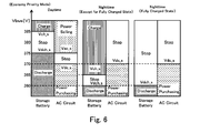
- the economy priority mode will be described with reference to Figs. 6 and 7 .
- the bidirectional DC-DC converter 12 and the third power conversion device 13 are operated to decrease a cost of power consumption.
- the information collecting portion 10a acquires fee information about a power purchasing price and a power selling price of a commercial AC power supply which are set to each predetermined time zone (the second information collecting portion 10a).
- the power selling price is separately set in daytime (for example, from 6 a.m. to 6 p.m.) and at nighttime (for example, from 6 p.m. to 6 a.m.), and the power selling price in the daytime is higher than the power selling price at nighttime.
- the information collecting portion 10a according to the present embodiment is configured to acquire information about whether the storage battery 3 is in a fully charged state and to then output the information to the operation control portion 10c.
- the power selling is more economically advantageous than the charging of excess generated power into the storage battery 3. Accordingly, by giving priority to the power selling over the charge into the storage battery 3, it is possible to reduce the cost of the power consumption.
- the power purchasing is more economically advantageous than discharging from the storage battery 3 in a time zone at nighttime in which the power selling price is set low. Therefore, priority is given to the power purchasing over the discharge from the storage battery 3, and the charge is performed unless the storage battery 3 is in the fully charged state.
- the operation control portion 10c respectively sets the charge starting voltage Vch_s, the DC-AC starting voltage Vac_s, the discharge starting voltage Vdch_s and the AC-DC starting voltage Vdc_s in a time zone in the daytime in which the power selling price is set high while the economy priority mode is set.
- a time zone at nighttime in which the power selling price is set low and the power generated from the photovoltaic power generation device 2 becomes zero is divided into the case where a fully charged state is not obtained and the case where the fully charged state is obtained.
- the charge starting voltage Vch_s, the discharge starting voltage Vdch_s, the DC-AC starting voltage Vac_s, and the AC-DC starting voltage Vdc_s are respectively set as shown in the following Equation 3 in the case where the fully charged state is not obtained, and as shown in the following Equation 4 in the case where the fully charged state is obtained.
- the operation control portion 10c respectively sets the charge starting voltage Vch_s, the DC-AC starting voltage Vac_s and the discharge starting voltage Vdch_s, and the AC-DC starting voltage Vdc_s to 385 [V], 375 [V], and 370 [V]. Consequently, in the case where the power generated from the photovoltaic power generation device 2 is large and is higher than the consumed power of the loading device 4 (the case where Vbus is equal to or higher than 375 [V]), excess generated power is supplied to the AC power system ESA so that the power selling is performed. In the case where the generated power further becomes excess (the case where Vbus is equal to or higher than 385 [V]), for example, the case where an amount of power selling is limited, the storage battery 3 is charged.
- the power of the storage battery 3 is first supplied to the DC power distribution system ESD. Furthermore, in the case where the voltage Vbus of the DC power distribution system ESD is reduced so that the value of the discharging current becomes greater than the maximum discharging current value Idch_max (corresponding to the case where Vbus is equal to or lower than 370 [V]), the power purchasing is performed. As shown in Fig. 7 , the value of the maximum discharging current value Idch_max may be appropriately set depending on the amount of power stored in the storage battery 3. With such a structure, it is possible to prolong a time until the storage battery 3 becomes an empty state.
- the operation control portion 10c respectively sets the charge starting voltage Vch_s, the discharge starting voltage Vdch_s, and the AC-DC starting voltage Vdc_s to 365[V], 360[V], and 370[V].
- the power generated from the photovoltaic power generation device 2 is zero and the discharge starting voltage Vdch_s is set to 360 [V]. Therefore, the voltage Vbus of the DC power distribution system ESD is not actually raised to be higher than 370 [V] of the AC-DC starting voltage Vdc_s.
- the AC-DC converter 13b is set to a stopping state in a region in which the voltage Vbus of the DC power distribution system ESD is equal to or higher than 370 [V].
- the operation control portion 10c respectively sets the discharge starting voltage Vdch_s and the AC-DC starting voltage Vdc_s to 360 [V] and 370 [V].
- the discharge starting voltage Vdch_s is set to 360 [V].
- the voltage Vbus of the DC power distribution system ESD is not raised to be higher than 370 [V] of the AC-DC starting voltage Vdc_s.
- the bidirectional DC-DC converter 12 is set to a stopping state in a region in which the voltage Vbus of the DC power distribution system ESD is equal to or higher than 370 [V].
- the AC-DC converter 13b is set to the stopping state in a region in which the voltage Vbus of the DC power distribution system ESD is equal to or higher than 370 [V].
- the leveling mode will be described with reference to Fig. 8 .
- an operation is performed so as to level power supplied from the AC power system ESA to the DC power distribution system ESD as much as possible.
- a peak of power supplied from the AC power system ESA that is, a peak of power for power purchasing
- it is expected to control the peak of generated power in a power company.
- a unit price of the power purchasing is increased when the peak value of power for power purchasing is made greater. In these cases, it is possible to reduce a power purchasing fee by suppressing the peak value of the power for power purchasing.
- the information collecting portion 10a acquires an actual value of the consumed power of the loading device 4 and an actual value of the amount of power generated from the photovoltaic power generation device 2 (the third information collecting portion 10a). More specifically, in the present embodiment, the information collecting portion 10a records a value of a current flowing through the loading device 4 and the voltage Vbus of the DC power distribution system, and the output current Ipv and the output voltage Vpv of the photovoltaic power generation device 2 per hour.
- the actual value of the consumed power of the loading device 4 is obtained by a sum of a current flowing through the loading device multiplied by the voltage Vbus of the DC power distribution system per unit time (per hour in the present embodiment), and the actual value of the amount of power generated from the photovoltaic power generation device is obtained by a sum of the output current Ipv multiplied by the output voltage Vpv per unit time.
- a broken line G1 indicates a transition of the actual value of the amount of power generated from the photovoltaic power generation device 2
- a solid line G2 indicates a transition of the actual value of the consumed power of the loading device 4
- a solid line G3 indicates a transition of the power for power purchasing
- a dotted line G4 indicates a maximum value of the power for power purchasing.
- the operation control portion 10c determines a maximum value of the power for power purchasing depending on the actual value of the consumed power of the loading device 4 and the actual value of the amount of power generated from the photovoltaic power generation device 2 which are acquired by the information collecting portion 10a, and sets a maximum AC-DC current value Iad_max depending on the maximum value of the power for power purchasing which is thus determined.
- expected power for power purchasing which is required per day is obtained from the actual value of the consumed power of the loading device 4 and the actual value of the amount of power generated from the photovoltaic power generation device 2 per day which are acquired by the information collecting portion 10a, a value having room for a value obtained by dividing the expected power for power purchasing per day by hour (24) is set to a maximum value of the power for power purchasing (see the dotted line G4 in Fig. 8 ), and the maximum AC-DC current value Iad_max is obtained from the maximum value of the power for power purchasing.
- the charge starting voltage Vch_s and the discharge starting voltage Vdch_s are set in the same manner as the CO 2 reduction mode, and both of them are set to 375 [V]. Moreover, the AC-DC starting voltage Vdc_s and the charge starting voltage Vch_s are set to, for example, 400 [V], because the power purchasing is always performed in the present embodiment.
- the current value of the DC power distribution system ESD becomes smaller than the maximum AC-DC current value Iad_max if the consumed power of the loading device 4 is lower than a maximum value G4 of the power for power purchasing (the case of time zones t1 and t6 in Fig. 8 ). Accordingly, power is supplied from the AC power system ESA to the DC power distribution system ESD so that the operation of the bidirectional DC-DC converter 12 is stopped.
- the AC-DC converter 13b When the consumed power of the loading device 4 is increased so that the power for power purchasing is increased and the current value of the AC-DC converter 13b reaches the maximum AC-DC current value Iad_max (the case of a time zone t5 in Fig. 8 ), the AC-DC converter 13b is operated such that the current value does not exceed the maximum AC-DC current value Iad_max. In this case, when the voltage Vbus of the DC power distribution system ESD is reduced to reach the discharge starting voltage Vdch_s, the bidirectional DC-DC converter 12 performs a discharging operation.
- the bidirectional DC-DC converter 12 performs a discharging operation if the voltage Vbus of the DC power distribution system ESD is reduced (becomes equal to or lower than 375 [V], for example).
- the power generated from the photovoltaic power generation device 2 is increased so that the total of the generated power and the maximum value G4 of the power for power purchasing is greater than the consumed power of the loading device 4 (the case of the time zone t1 in Fig.
- the bidirectional DC-DC converter 12 performs a charging operation if the voltage Vbus of the DC power distribution system ESD is raised (becomes equal to or higher than 375 [V], for example).
- a slant line portion E1 indicates an amount of power to be charged to the storage battery 3 and a vertical line portion E2 indicates an amount of power to be discharged from the storage battery 3.
- the current value of the DC power distribution system ESD is smaller than the maximum AC-DC current value Iad_max so that power is supplied from the AC power system ESA to the DC power distribution system ESD, and the bidirectional DC-DC converter 12 stops the operation.
- the storage battery deterioration relieving mode will be described with reference to Fig. 9 .
- an operation is performed to prolong a lifetime of the storage battery 3.
- a rapid charging mode for charging the storage battery 3 more rapidly than usual a normal charging/discharging mode which is preset by the operation mode setting portion 10b and a little discharging mode for discharging the storage battery 3 more slowly than usual are set.
- Each of set values in the normal charging/discharging mode according to the present embodiment may be equal to each of set values in the CO 2 reduction mode, the economy priority mode, the leveling mode, and the like.
- the lithium ion battery is assumed as described above.
- the lithium ion battery is alternately subjected to a rapid discharge and a rapid charge repetitively, an internal resistance is gradually increased so that an output deterioration phenomenon occurs.
- a concentration of a lithium ion in an electrolyte held between a positive plate and a negative plate in a power generation element may fluctuate with the output deterioration phenomenon of a secondary battery. If the concentration of the lithium ion in the held electrolyte fluctuates, the internal resistance of the lithium ion battery may increase.
- the charging and discharging conditions of the storage battery 3 be regulated appropriately to repeat the charge/discharge. Consequently, it is possible to suppress an increase in the internal resistance, thereby suppressing a deterioration to maintain the lifetime of the storage battery 3 to be longer.
- the rapid charging mode for performing charge more rapidly than usual is executed, and when the charge is ended, the little discharging mode for performing discharge more slowly than usual is executed, and when the discharge is ended, the rapid charging mode is executed.
- the information collecting portion 10a successively acquires deterioration information about a power storage device when the storage battery deterioration relieving mode is set (the fourth information collecting portion 10a). More specifically, the information collecting portion 10a according to the present embodiment acquires information about a concentration of a lithium ion of a lithium ion battery and a measured value of an internal resistance.
- the operation mode setting portion 10b determines whether the power storage device is deteriorated or not based on the deterioration information while the storage battery deterioration relieving mode is set by an external input, and when determining that the power storage device is deteriorated, the operation mode setting portion 10b sets the rapid charging mode to the operation control portion 10c, sets the little discharging mode to the operation control portion 10c when the power storage device is fully charged, sets the rapid charging mode to the operation control portion 10c when the discharge of the power storage device is ended, and sets the normal charging/discharging mode to the operation control portion 10c when the power storage device is fully charged.
- the operation control portion 10c sets the charging current value Ich to be greater than the charging current value Ich in the normal charging/discharging mode depending on the characteristic of the power storage device, and when the little discharging mode is set, the operation control portion 10c sets the maximum discharging current value Idch_max to be smaller than the maximum discharging current value Idch_max in the normal charging/discharging mode depending on the characteristic of the power storage device.
- Fig. 9 shows an operation in the case where the storage battery deterioration relieving mode is set. If the storage battery deterioration relieving mode is set through the display device 5 shown in Fig. 1 (Step #1), the operation mode setting portion 10b first sets the normal charging/discharging mode to the operation control portion 10c (Step #2). The operation control portion 10c sets each of a first control parameter and a second control parameter depending on the normal charging/discharging mode.
- the operation mode setting portion 10b determines whether the storage battery 3 is deteriorated or not based on the deterioration information (Step #3), and sets the rapid charging mode to the operation control portion 10c when determining that the storage battery 3 is deteriorated (a branch of YES in Step #3) (Step #4).
- the rapid charging mode is set, the operation control portion 10c sets the charging current value Ich to be greater than the charging current value Ich in the normal charging/discharging mode.
- the operation mode setting portion 10b sets the little discharging mode to the operation control portion 10c (Step #6) when the storage battery 3 is fully charged (a branch of YES in Step #5).
- the operation control portion 10c sets the maximum discharging current value Idch_max to be smaller than the maximum discharging current value Idch_max in the normal charging/discharging mode. Subsequently, when a residual amount of the storage battery 3 is zero (a branch of YES in Step #7), the operation mode setting portion 10b sets the rapid charging mode to the operation control portion 10c again (Step #8). In Step #4, the operation control portion 10c sets the charging current value Ich to be greater than the charging current value Ich in the normal charging/discharging mode. Therefore, the setting of the charging current value Ich is not changed.
- the operation mode setting portion 10b sets the normal charging/discharging mode to the operation control portion 10c (Step #2).
- the operation control portion 10c sets the charging current value Ich and the maximum discharging current value Idch_max to the normal charging/discharging mode.
- each of set values of the first control parameter and the second control parameter is acquired from the outside.
- the external operation mode it is possible to optionally add the external operation mode.
- a second embodiment of the control system 1 according to the present invention will be described with reference to Fig. 10 .
- the first control parameter is fixedly set in the CO 2 reduction mode according to the first embodiment
- a first control parameter is set to be switched depending on a residual amount of a storage battery 3 (corresponding to a second driving mode) in a CO 2 reduction mode according to the present embodiment.
- a discharge starting voltage Vdch_s and a charge starting voltage Vch_s which are the first control parameters are set so that the larger the residual amount of the storage battery 3 is, the larger the discharge starting voltage Vdch_s and the charge starting voltage Vch_s are.
- an information collecting portion 10a While the CO 2 reduction mode is set, an information collecting portion 10a according to the present embodiment appropriately acquires an amount of power stored in a power storage device from a second power conversion device at a certain interval of 10 to 60 minutes or the like, for example (the first information collecting portion 10a).
- an operation control portion 10c While the second driving mode is set, an operation control portion 10c according to the present embodiment appropriately sets the charge starting voltage Vch_s and the discharge starting voltage Vdch_s depending on an amount of stored power.
- Fig. 10 shows a voltage setting method in the CO 2 reduction mode according to the present embodiment.
- the discharge starting voltage Vdch_s is set to 0 [V] in the case where the residual amount of the storage battery 3 is "empty”, to 360 [V] in the case of "small” or “middle”, and to 375 [V] in the case of "large” or “full”, respectively.
- the charge starting voltage Vch_s is set to 365 [V] in the case where the residual amount of the storage battery 3 is "empty” or “small”, to 370[V] in the case of "middle”, to 375 [V] in the case of "large”, and to 400 [V] in the case of "full”, respectively.
- a maximum discharging current value Idch_max of a bidirectional DC-DC converter 12 is set to 10 [A].
- a DC-AC starting voltage Vac_s, a AC-DC starting voltage Vdc_s, and a maximum AC-DC current value Iad_max of an AC-DC converter 13b are to 380 [V], 370 [V], and 10[A], respectively.
- the first control parameter and the second control parameter are set in the same manner as the setting of the first control parameter and the second control parameter in the CO 2 reduction mode according to the first embodiment.
- the discharging operation is performed with priority over the power purchasing.
- power generated from a photovoltaic power generation device 2 is larger than consumed power of a loading device 4 (the case where the voltage Vbus of the DC power distribution system ESD is higher than the charge starting voltage Vch_s)
- a charging operation is performed.
- the charge starting voltage Vch_s and the discharge starting voltage Vdch_s are set to be lower than that in the case of "large” as shown in Fig. 10 .
- the power generated from the photovoltaic power generation device 2 is lower than the consumed power of the loading device 4 (the case where the voltage Vbus of the DC power distribution system ESD is lower than the AC-DC starting voltage Vdc_s), the power purchasing is performed with priority over the discharging operation.
- the power obtained by the power purchasing is charged into the storage battery 3 when the voltage Vbus of the DC power distribution system ESD is higher than the charge starting voltage Vch_s and is lower than the AC-DC starting voltage Vdc_s.
- the discharging operation is performed.
- the power obtained by the power purchasing is charged into the storage battery 3 when the voltage Vbus of the DC power distribution system ESD is higher than the charge starting voltage Vch_s and is lower than the AC-DC starting voltage Vdc_s. Moreover, the discharging operation is not performed.
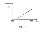
- a third embodiment of the control system 1 according to the present invention will be described with reference to Fig. 11 .
- a power selling price is varied between a time zone in daytime and a time zone at nighttime in the economy priority mode according to the first embodiment
- the description will further be given on the assumption of the case where a power purchasing price is increased when a certain amount of power or more is purchased in a time zone at nighttime in the present embodiment.
- an economy priority mode there is performed a control for reducing an amount of power to be supplied from an AC power system ESA to a DC power distribution system ESD to a certain amount or less in a time zone at nighttime.
- an operation control portion 10c sets a maximum AC-DC current value Iad_max depending on an amount of power for which a power purchasing price is increased.
- supply of power from the AC power system ESA to the DC power distribution system ESD is limited.
- a voltage Vbus of the DC power distribution system ESD is reduced.
- the operation control portion 10c according to the present embodiment sets a charging current Ich to be decreased depending on a reduction in the voltage Vbus of the DC power distribution system ESD. Consequently, it is possible to stabilize the voltage Vbus of the DC power distribution system ESD.
- a control system 1B according to the present invention in the present embodiment includes, in addition to each of the structures according to the first embodiment, a fourth power conversion device 14 for performing voltage conversion between a second power storage device configured to freely carry out connection and disconnection to and from a DC power distribution system ESD and the DC power distribution system ESD, thereby supplying power from one side to the other side.
- a storage battery 6 is one example of the second power storage device in the present embodiment, and is assumed to be a storage battery which is to be mounted on an electric vehicle or a hybrid car. Although description will be given on the assumption that the storage battery 6 according to the present embodiment is a lithium ion battery, other batteries may be employed.
- the storage battery 6 is configured to be connected to the fourth power conversion device 14 which is provided fixedly in the DC power distribution system ESD through a connector.
- the bidirectional DC-DC converter 14 is one example of the fourth power conversion device in the present embodiment, and similarly to the bidirectional DC-DC converter 12, the bidirectional DC-DC converter 14 is configured to control a direction, a start, and a stop of power supply depending on a charge starting voltage Vch_s, a discharge starting voltage Vdch_s, a charging current value Ich, a charging voltage value Vch, a discharging voltage value Vdch, and a maximum discharging current value Idch_max.
- an information collecting portion 10a is configured to acquire connection information indicative of disconnection or connection from or to the storage battery 6 disconnected or connected. Moreover, the information collecting portion 10a according to the present embodiment acquires information about a whole capacity of storage batteries which are connected and a residual amount of each of the storage batteries.
- An operation control portion 10c acquires the connection information about the storage battery 6 from the information collecting portion 10a, operates the bidirectional DC-DC converter 14 corresponding to the storage battery 6 which is connected in the case where the storage battery 6 is connected, and sets the charge starting voltage Vch_s, the discharge starting voltage Vdch_s, the charging current value Ich, the charging voltage value Vch, the discharging voltage value Vdch and the maximum discharging current value Idch_max. Moreover, in the case where the storage battery 6 is disconnected, the bidirectional DC-DC converter 14 corresponding to the disconnected storage battery 6 is stopped.
- the storage battery 6 is assumed to be an on-vehicle storage battery. Therefore, it is also possible to employ such a structure as to charge the storage battery 6 with priority over the other storage battery 3 which is connected fixedly. More specifically, the operation control portion 10c sets the charge starting voltage Vch_s of the storage battery 6 to have a smaller value than the charge starting voltage Vch_s of the storage battery 3.
- the present embodiment it is possible to utilize the storage battery 6 configured to be freely connected or disconnected. Therefore, the present embodiment can be applied to the case of a power failure or the case where consumed power of a loading device is temporarily increased and power purchasing is to be suppressed or the like, for example.
- the information collecting portion 10a acquires an appropriate residual amount for every storage battery, and as shown in Fig. 13 , the operation control portion 10c appropriately switches the setting of the discharge starting voltage Vdch_s depending on the residual amount of the storage battery 3 which is acquired by the information collecting portion 10a.
- the discharging operation is preferentially started from the storage battery 3 having a larger amount. If only a part of the storage batteries 3 repeats charging/discharging, only the part of the storage batteries 3 is deteriorated. In the present embodiment, however, the discharging operation is preferentially started from the storage battery 3 having a larger residual amount. As a result, therefore, the residual amounts of the plurality of storage batteries 3 are made uniform so that it is possible to prevent only a part of the storage batteries 3 from being charged/discharged and thus deteriorated.
- the storage battery deterioration relieving mode is not selected by a user but is always set, and when it is determined that the storage battery 3 is deteriorated, the setting of the charging current value Ich in the charging operation is made to be the same as the setting of the charging current value Ich in the rapid charging mode, and the setting of the maximum discharging current value Idch_max in the discharging operation is made to be the same as the setting of the maximum discharging current value Idch_max in the little discharging mode to execute the external operation mode set by the user (the CO 2 reduction mode, the economy priority mode, the leveling mode, and the external command mode).
Landscapes
- Engineering & Computer Science (AREA)
- Power Engineering (AREA)
- Supply And Distribution Of Alternating Current (AREA)
- Charge And Discharge Circuits For Batteries Or The Like (AREA)
- Secondary Cells (AREA)
- Direct Current Feeding And Distribution (AREA)
Abstract
Description
- The present invention relates to a control system for direct current (DC) power distribution including a DC power distribution system for supplying DC power to a loading device, a first power conversion device for performing voltage conversion over power generated from a photovoltaic power generation device and supplying the converted power to the DC power distribution system, a second power conversion device for performing voltage conversion between a power storage device and the DC power distribution system, and a third power conversion device for performing power conversion between an alternate current (AC) system and the DC power distribution system.
- For example, as shown in
Fig. 14 , some conventional control systems for DC power distribution include a DC power distribution system ESD for supplying power to a loading device, asystem interconnection unit 101, apower storage unit 102, aflywheel unit 103, a windpower generation unit 104, a photovoltaicpower generation unit 105, and a loading unit 106 (seePatent Document 1, for example). - Although not illustrated, the
system interconnection unit 101 is configured to include a DC-AC inverter for converting power of the DC power distribution system ESD and supplying the converted power to an AC power system ESA, and an AC-DC converter for converting power of the AC power system ESA and supplying the converted power to the DC power distribution system ESD. Moreover, although not illustrated, thepower storage unit 102 is configured to include a power storage device and a power conversion device for performing voltage conversion between the power storage device and the DC power distribution system ESD, thereby supplying power from one side to the other side. Similarly, although not illustrated, theflywheel unit 103 is configured to include a flywheel and a power conversion device for performing voltage conversion between the flywheel and the DC power distribution system ESD, thereby supplying power from one side to the other side. Although not illustrated, the windpower generation unit 104 is configured to include a wind power generation device and a power conversion device for performing voltage conversion over power generated by the wind power generation device, thereby supplying the converted power to the DC power distribution system ESD. Although not illustrated, the photovoltaicpower generation unit 105 is configured to include a photovoltaic power generation device and a power conversion device for performing voltage conversion over power generated by the photovoltaic power generation device, thereby supplying the converted power to the DC power distribution system ESD. - In the control system for DC power distribution described above, as shown in
Fig. 15 , each of the power conversion devices connected to the DC power distribution system performs an operation control based on the voltage of the DC power distribution system, independently and irrespective of operations of other power conversion devices. - Patent Document 1 : Japanese Unexamined Patent Publication No.
2003-339118 - However, in the control system for
DC power distribution 100 described above, each power conversion device is operated irrespective of the operations of the other power conversion devices. For this reason, there is a problem in that it is hard to flexibly take a measure against a demand of a user of the control system for DC power distribution or a change in restrictions depending on social conditions or the like. - More specifically, the power conversion device of the
power storage unit 102 shown inFig. 14 performs only a preset operation in which discharge is performed until the stored power becomes empty when a load of a power storage device is increased, and charge is performed until a fully charged state is obtained when the stored power becomes empty. For example, there is a problem in that a driving control for reducing CO2 at a maximum, a driving control for relieving a deterioration in a storage battery or the like cannot be flexibly switched depending on a demand of a user or the like. - Furthermore, in the control system for
DC power distribution 100 described above, a plurality of power conversion devices are operated irrespective of the operations of the other power supply devices. For this reason, for example, when the plurality of power conversion devices are set to perform output at the same voltage, there has been a problem in that the plurality of power conversion devices are influenced by mutual controls, resulting in an unstable control system. - The present invention has been made in view of the above problems, and an object thereof is to provide a control system for DC power distribution including a plurality of power supply devices which can flexibly take a measure against a demand of a user or a change in restrictions depending on social conditions by having the plurality of power conversion devices cooperatively operate with each other.
- A control system for DC power distribution according to the present invention for achieving the above object has a first feature that the control system comprises:
- a DC power distribution system for supplying DC power to a loading device;
- a first power conversion device for performing voltage conversion over power generated from a photovoltaic power generation device, thereby supplying the converted power to the DC power distribution system;
- a second power conversion device for performing voltage conversion between a first power storage device which is always connected to the DC power distribution system and the DC power distribution system, thereby supplying power from one side to the other side;
- a third power conversion device for performing power conversion between an AC power system and the DC power distribution system, thereby supplying power from one side to the other side;
- an operation mode setting portion for setting an operation mode of the control system for DC power distribution depending on operation mode determination information for setting the operation mode; and
- an operation control portion for setting a first control parameter to the second power conversion device and setting a second control parameter to the third power conversion device depending on the operation mode set by the operation mode setting portion,
- the second power conversion device controls a direction, a start, and a stop of power supply depending on a voltage of the DC power distribution system and the first control parameter, and
- the third power conversion device controls a direction, a start, and a stop of power supply depending on the voltage of the DC power distribution system and the second control parameter.
- The control system for DC power distribution according to the present invention for achieving the above object has a second feature that the control system comprises:
- a DC power distribution system for supplying DC power to a loading device;
- a first power conversion device for performing voltage conversion over power generated from a photovoltaic power generation device, thereby supplying the converted power to the DC power distribution system;
- a second power conversion device for performing voltage conversion between a first power storage device which is always connected to the DC power distribution system and the DC power distribution system, thereby supplying power from one side to the other side;
- a third power conversion device for performing power conversion between an AC power system and the DC power distribution system, thereby supplying power from one side to the other side;
- an operation mode setting portion for setting an operation mode of the control system for DC power distribution depending on operation mode determination information for setting the operation mode; and
- an operation control portion for setting a first control parameter and a second control parameter, respectively, depending on the operation mode set by the operation mode setting portion, and
- the operation control portion controls a direction, a start, and a stop of power supply of the second power conversion device depending on a voltage of the DC power distribution system and the first control parameter, and controls a direction, a start, and a stop of power supply of the third power conversion device depending on the voltage of the DC power distribution system and the second control parameter.
- The control system for DC power distribution according to the present invention having any of the above features has a third feature that
the first control parameter includes a charge starting voltage for defining the voltage of the DC power distribution system at which power starts to be supplied from the DC power distribution system to the first power storage device and a discharge starting voltage for defining the voltage of the DC power distribution system at which power starts to be supplied from the first power storage device to the DC power distribution system, and
the second control parameter includes a DC-AC (DC to AC conversion) starting voltage for defining the voltage of the DC power distribution system at which power starts to be supplied from the DC power distribution system to the AC power system, and a AC-DC (AC to DC conversion) starting voltage for defining the voltage of the DC power distribution system at which power starts to be supplied from the AC power system to the DC power distribution system. - The control system for DC power distribution according to the present invention having the above features has a fourth feature that the control system comprises an information collecting portion for acquiring parameter setting information for setting the first control parameter and the second control parameter, and
the operation control portion sets the first control parameter and the second control parameter based on the parameter setting information acquired by the information collecting portion when the operation mode is changed by the operation mode setting portion. - The control system for DC power distribution according to the present invention having the above features has a fifth feature that
the operation mode includes a first driving mode for reducing an amount of power to be supplied from the AC power system to the DC power distribution system, and
the operation control portion sets the first control parameter and the second control parameter such that the DC-AC starting voltage is higher than the charge starting voltage and the discharge starting voltage is higher than the AC-DC starting voltage when the first driving mode is set. - The control system for DC power distribution according to the present invention having the above third to fifth features has a sixth feature that
the operation mode includes a second driving mode for switching the setting of the first control parameter depending on an amount of power stored in the first power storage device,
the control system includes a first information collecting portion for appropriately acquiring the amount of power stored in the first power storage device from the second power conversion device while the second driving mode is set, and
the operation control portion appropriately sets the charge starting voltage and the discharge starting voltage depending on the amount of the stored power while the second driving mode is set. - The control system for DC power distribution according to the present invention having the above third to sixth features has a seventh feature that
the AC power system is connected to a commercial AC power supply,
the operation mode includes a third driving mode for controlling a power fee,
the control system includes a second information collecting portion for acquiring fee information about a power purchasing price and a power selling price of the commercial AC power supply which are set for each predetermined time zone when the third driving mode is set, and
the operation control portion
sets the charge starting voltage to be higher than the DC-AC starting voltage and sets the discharge starting voltage to be higher than the AC-DC starting voltage in a time zone in which the power selling price is set high while the third driving mode is set, and
sets the charge starting voltage to be lower than the AC-DC starting voltage in a time zone in which the power selling price is set low while the third driving mode is set. - The control system for DC power distribution according to the present invention having the above features has an eighth feature that
the first control parameter includes a charging current value in a case where power is supplied from the DC power distribution system to the first power storage device, and
the operation control portion sets the charging current value to be decreased depending on a drop in the voltage of the DC power distribution system. - The control system for DC power distribution according to the present invention having any one of the above features has a ninth feature that
the second control parameter includes a maximum AC-DC current value of a current to be supplied from the AC power system to the DC power distribution system in the third power conversion device. - The control system for DC power distribution according to the present invention having the above features has a tenth feature that
the operation mode includes a fourth driving mode for leveling power to be supplied from the AC power system to the DC power distribution system,
the control system includes a third information collecting portion for acquiring an actual value of consumed power of the loading device and an actual value of an amount of power generated from the photovoltaic power generation device when the fourth driving mode is set, and
the operation control portion sets the maximum AC-DC current value depending on the actual value of the consumed power and the actual value of the amount of the generated power when the fourth driving mode is set. - The control system for DC power distribution according to the present invention having any one of the above features has an eleventh feature that
the first control parameter includes a charging current value in a case where power is supplied from the DC power distribution system to the first power storage device, and a maximum discharging current value in a case where power is supplied from the first power storage device to the DC power distribution system. - The control system for DC power distribution according to the present invention having the above features has a twelfth feature that
the operation mode includes a rapid charging mode for charging the first power storage device more rapidly than usual, a normal charging/discharging mode which is preset by the operation mode setting portion, and a little discharging mode for discharging the first power storage device more slowly than usual,
the control system includes a fourth information collecting portion for acquiring deterioration information about the first power storage device,
the operation mode setting portion determines whether the first power storage device is deteriorated or not based on the deterioration information, when determining that the first power storage device is deteriorated, the operation mode setting portion sets the operation mode to the rapid charging mode, sets the operation mode to the little discharging mode when the first power storage device is fully charged, sets the operation mode to the rapid charging mode when the discharge of the first power storage device is ended, and sets the operation mode to the normal charging/discharging mode when the first power storage device is fully charged, and
the operation control portion sets the charging current value to be greater than the charging current value in the normal charging/discharging mode depending on a feature of the first power storage device when the rapid charging mode is set, and
sets the maximum discharging current value to be smaller than the maximum discharging current value in the normal charging/discharging mode depending on the feature of the first power storage device when the little discharging mode is set. - The control system for DC power distribution according to the present invention having any one of the above features has a thirteenth feature that
the operation control portion sets a third control parameter to the first power conversion device, and
the first power conversion device performs either of a normal operation for performing an operation such that output power is maximized, or a constant voltage operation for performing an operation such that an output voltage value is constant, depending on the voltage of the DC power distribution system and the third control parameter. - The control system for DC power distribution according to the present invention having the above features has a fourteenth feature that the third control parameter includes a constant voltage driving starting voltage for defining the voltage of the DC power distribution system at which the constant voltage operation is started.
- The control system for DC power distribution according to the present invention having any one of the above features has a fifteenth feature that the control system further comprises a fourth power conversion device for performing voltage conversion between a second power storage device and the DC power distribution system, thereby supplying power from one side to the other side, the second power storage device being configured to freely perform connection and disconnection to and from the DC power distribution system.
- According to the control system for DC power distribution having the features described above, each of the plurality of power conversion devices can be made to operate cooperatively easily by only setting the control parameter. Consequently, also in the case where the number of the power supply devices is increased/decreased or the case where a power failure has occurred in an AC power system, for example, the case where a part of the power supply devices are stopped due to a breakdown or the like, it is possible to stably implement an operation control which flexibly takes a measure against a demand of a user or a change in restrictions depending on social conditions. Furthermore, in the control system for DC power distribution having the feature described above, the plurality of power conversion devices are cooperatively operated. Therefore, it is possible to prevent the control system from becoming unstable by the influence of the mutual controls.
- Moreover, according to the control system for DC power distribution having the fifth and sixth features, the amount of power to be supplied from the AC power system to the DC power distribution system is reduced. Therefore, it is possible to control the amount of discharge of CO2. Furthermore, according to the control system for DC power distribution having the seventh feature, power selling is preferentially performed at the time when a power selling price is set high. Therefore, it is possible to reduce a power fee. According to the control system for DC power distribution having the eighth feature, the charging current is set to be decreased depending on the drop in the voltage of the control system for DC power distribution. Therefore, it is possible to stabilize the voltage of the DC power distribution system. The control system for DC power distribution having the ninth and tenth features levels the power to be supplied from the AC power system to the DC power distribution system. Therefore, it is possible to suppress fluctuation in power generated by a power company in the case where the AC power system is connected to a commercial AC power supply, for example. According to the control system for DC power distribution having the eleventh and twelfth features, when it is determined that the first power storage device is deteriorated, it is possible to relieve the deterioration in the power storage device by executing the rapid charging mode, the little discharging mode, and the rapid charging mode, in this order.
-
-
Fig. 1 is a schematic block diagram showing an example of a schematic structure of a control system for DC power distribution and peripheral devices according to a first embodiment of the present invention. -
Fig. 2 is a schematic block diagram showing an example of a structure of a display device connected to the control system for DC power distribution according to the present invention. -
Fig. 3 is a graph showing a relationship among an amount of sunshine, an output voltage and an output current of a photovoltaic power generation device. -
Fig. 4 is a table showing an example of operation modes of the control system for DC power distribution according to the first embodiment of the present invention. -
Fig. 5 is a table showing a voltage setting method of a CO2 reduction mode of the control system for DC power distribution according to the first embodiment of the present invention. -
Fig. 6 is a table showing a voltage setting method of an economy priority mode of the control system for DC power distribution according to the first embodiment of the present invention. -
Fig. 7 is a graph showing a method of setting the maximum discharging current value in the economy priority mode of the control system for DC power distribution according to the first embodiment of the present invention. -
Fig. 8 is a graph showing an actual value of consumed power of a loading device and an actual value of an amount of power generated from the photovoltaic power generation device in a leveling mode of the control system for DC power distribution according to the first embodiment of the present invention. -
Fig. 9 is a flowchart showing a storage battery deterioration relieving mode of the control system for DC power distribution according to the first embodiment of the present invention. -
Fig. 10 is a table showing a voltage setting method of a CO2 reduction mode of a control system for DC power distribution according to another embodiment of the present invention. -
Fig. 11 is a table showing a method of setting a charging current value in an economy priority mode of the control system for DC power distribution according to another embodiment of the present invention. -
Fig. 12 is a schematic block diagram showing an example of a schematic structure of the control system for DC power distribution and peripheral devices according to another embodiment of the present invention. -
Fig. 13 is a table showing a method of setting a discharge starting voltage in the storage battery deterioration relieving mode of the control system for DC power distribution according to another embodiment of the present invention. -
Fig. 14 is a schematic block diagram showing an example of a schematic structure of a control system for DC power distribution according to the prior art. -
Fig. 15 is a block diagram showing an operation of the control system for DC power distribution according to the prior art. - An embodiment of a control system for DC power distribution according to the present invention (hereinafter, appropriately referred to as "a control system according to the present invention") will be described below with reference to the drawings.
- A first embodiment of the control system according to the present invention will be described with reference to
Figs. 1 and2 . - First of all, a structure of a
control system 1 according to the present invention in the present embodiment will be described with reference toFigs. 1 and2 .Fig. 1 shows an example of a schematic structure of acontrol system 1A according to the present invention and peripheral devices, andFig. 2 shows an example of a display of adisplay device 5 connected to thecontrol system 1A according to the present invention. - As shown in
Fig. 1 , thecontrol system 1A according to the present invention is configured to include a DC power distribution system ESD for supplying DC power to aloading device 4, a firstpower conversion device 11 for performing voltage conversion over power generated by a photovoltaicpower generation device 2 and supplying the converted power to the DC power distribution system ESD, a secondpower conversion device 12 for performing voltage conversion between a firstpower storage device 3 and the DC power distribution system ESD and supplying the converted power from one side to the other side, a third power conversion device 13 for converting AC power to DC power or DC power to AC power between an AC power system ESA and the DC power distribution system ESD and supplying the converted power from one side to the other side, and anoperation control device 10 for setting an operation of thecontrol system 1A according to the present invention. - In the
control system 1A according to the present invention in the present embodiment, the AC power system ESA is connected to a commercial AC power supply (for example, a single-phase three-wire system 200 [V]), and the third power conversion device 13 is configured to carry out system interconnection to the AC power system ESA, thereby enabling a reverse power flow. There is employed a structure in which, when AC power is subjected to the reverse power flow and is thus supplied to the AC power system ESA, a power company performs purchase depending on an amount of power in accordance with a contract made between the power company and a user of thecontrol system 1 according to the present invention. - The
operation control device 10 includes an operationmode setting portion 10b for setting an operation mode depending on operation mode determination information for setting an operation mode of thecontrol system 1A according to the present invention, and anoperation control portion 10c for setting a first control parameter to the second power conversion device and a second control parameter to the third power conversion device 13, respectively, depending on the operation mode set by the operationmode setting portion 10b. - In the present embodiment, an external operation mode to be presented to a user and an internal operation mode to be set to an operation control portion 11c by an operation mode setting portion 11b are assumed as the operation mode.
- The first control parameter according to the present embodiment includes a charge starting voltage Vch_s for defining a voltage of the DC power distribution system ESD at which power starts to be supplied from the DC power distribution system ESD to the first power storage device, a discharge starting voltage Vdch_s for defining the voltage of the DC power distribution system ESD at which power starts to be supplied from the first power storage device to the DC power distribution system ESD, a charging current value Ich and a charging voltage value Vch in the case where power is supplied from the DC power distribution system ESD to the first power storage device, and a discharging voltage value Vdch and a maximum discharging current value Idch_max in the case where power is supplied from the first power storage device to the DC power distribution system ESD.
- Moreover, the second control parameter according to the present embodiment includes a DC-AC starting voltage Vac_s for defining a voltage of the DC power distribution system ESD at which power starts to be supplied from the DC power distribution system ESD to the AC power system ESA, a AC-DC starting voltage Vdc_s for defining the voltage of the DC power distribution system ESD at which power starts to be supplied from the AC power system ESA to the DC power distribution system ESD, and a maximum AC-DC current value Iad_max of a current to be supplied from the AC power system ESA to the DC power distribution system ESD in the third power conversion device 13.
- The
operation control device 10 according to the present embodiment further includes aninformation collecting portion 10a for acquiring operation mode determination information from thedisplay device 5 configured to enable a user to input a setting of an operation mode and outputting the operation mode determination information to the operationmode setting portion 10b.Fig. 2 shows an example of the display of thedisplay device 5, and thedisplay device 5 has an external operation mode displayed thereon and has such a structure that the user performs selection. - In the present embodiment, the photovoltaic
power generation device 2 is configured by connecting, in series, a plurality of solar cell modules disposed on a roof of a building or the like, and serves to directly convert solar light into electrical energy, thereby generating DC power.Fig. 3 shows an example of a relationship among an amount of sunshine, an output voltage and an output current of the photovoltaicpower generation device 2. InFig. 3 , each of curved lines CV1 to CV3 shows an example of an IV characteristic for each amount of sunshine, and the curved line CV1 indicates the case where the amount of sunshine is small, the curved line CV2 indicates the case of a usual amount of sunshine and the curved line CV3 indicates the case where the amount of sunshine is large. - In the present embodiment, the DC-
DC converter 11 is one example of the first power conversion device and serves to convert the output voltage of the photovoltaicpower generation device 2 into a predetermined DC voltage. The DC-DC converter 11 performs a maximum power tracking control (an MPPT control) such that the photovoltaicpower generation device 2 outputs maximum power even in the case where the amount of sunshine fluctuates. More specifically, the DC-DC converter 11 detects an output current Ipv and an output voltage Vpv of the photovoltaicpower generation device 2 and performs a control to maximize Ipv x Vpv. For example, in the case where the amount of sunshine is indicated by the curved line CV3 shown inFig. 3 , an operation is performed on a point where the output current Ipv = Ip and the output voltage Vpv = Vp are obtained. - A voltage Vbus of the DC power distribution system ESD is changed based on a total power amount that is a total of output power of the DC-
DC converter 11, consumed power of theloading device 4, and discharging power or charging power through a charging/discharging operation of thestorage battery 3 which will be described below. The total of the respective amounts of power is obtained through addition by setting, as positive values, the output power of the DC-DC converter 11 and the discharging power of thestorage battery 3 which are to be supplied to the DC power distribution system ESD and setting, as negative values, the charging power of the storage battery and the consumed power of theloading device 4 which are to be supplied from the DC power distribution system ESD. The voltage Vbus is raised when the total power amount is positive, and the voltage Vbus is lowered when the total power amount is negative. For this reason, in the present embodiment, a constant voltage driving starting voltage Vpv_max is set to be a third control parameter in order to prevent an overvoltage of the DC power distribution system ESD. - When the voltage Vbus is lower than the constant voltage driving starting voltage Vpv_max, the DC-
DC converter 11 performs the MPPT control (a normal operation). When the voltage Vbus is higher than the constant voltage driving starting voltage Vpv_max, the DC-DC converter 11 stops the MPPT control and makes a transition to a constant voltage operation to cause an output voltage value to be a constant value so that the voltage Vbus does not exceed the constant voltage driving starting voltage Vpv_max. Similarly, the constant current driving starting voltage Ipv_max is set in order to prevent an overcurrent. In the present embodiment, since there is a possibility that the set values of the constant voltage driving starting voltage Vpv_max and the constant current driving starting voltage Ipv_max be changed in order to operate the DC-DC converter 11 cooperatively with other power conversion devices, the set values can be varied by theoperation control device 10. - Although the description has been given to the case where the first power conversion device is configured by one DC-
DC converter 11 in the present embodiment, the first power conversion device may be configured by connecting a plurality of DC-DC converters 11 in parallel, or other structures may be employed. - In the present embodiment, the
storage battery 3 is one example of the first power storage device and thestorage battery 3 is configured by a lithium ion battery. Although the lithium ion battery will be described as an example in the present embodiment, another battery such as sodium or sulfur battery may be used. Thestorage battery 3 charges the power supplied from the DC power distribution system ESD through a bidirectional DC-DC converter 12 which will be described below, and discharges the charged power to the DC power distribution system ESD through the bidirectional DC-DC converter 12. - In the present embodiment, the bidirectional DC-
DC converter 12 is one example of the second power conversion device and controls a power supplying direction (charging or discharging), and a start and a stop of power supply depending on the voltage of the DC power distribution system ESD and the first control parameter, that is, the charge starting voltage Vch_s, the discharge starting voltage Vdch_s, the charging current value Ich, the charging voltage value Vch, the discharging voltage value Vdch, and the maximum discharging current value Idch_max. - In a charging operation, the bidirectional DC-
DC converter 12 converts a current flowing from the DC power distribution system ESD into a charging current having the charging current value Ich or converts the voltage Vbus of the DC power distribution system ESD into a charging voltage having the charging voltage value Vch, thereby supplying power to thestorage battery 3. - More specifically, at the time of the charging operation, if a charging amount of the
storage battery 3 is small and the voltage Vbat of thestorage battery 3 is lower than the charging voltage value Vch, the bidirectional DC-DC converter 12 converts the current flowing from the DC power distribution system ESD into the charging current having the charging current value Ich and thus charges thestorage battery 3. When the charging amount is increased so that the value of the output voltage (charging voltage) of the bidirectional DC-DC converter 12 reaches the charging voltage value Vch, the value of the charging voltage is maintained to the charging voltage value Vch to perform charging until a fully charged state is obtained. When the fully charged state is obtained and the voltage Vbat of thestorage battery 3 reaches the charging voltage value Vch, the charging current becomes zero and the charging is thus stopped. - Furthermore, at the time of a discharging operation, the bidirectional DC-
DC converter 12 converts the voltage Vbat of thestorage battery 3 into the discharging voltage value Vdch, and converts a current flowing to the DC power distribution system ESD so as not to exceed the maximum discharging current value Idch_max. Consequently, if the value of the voltage Vbus of the DC power distribution system ESD is smaller than the discharging voltage value Vdch, the bidirectional DC-DC converter 12 supplies the power stored in thestorage battery 3 to the DC power distribution system ESD. - Although the description has been given on the assumption of the case where the second power conversion device is configured by one bidirectional DC-
DC converter 12 in the present embodiment, it is also possible to employ other structures, for example, a structure including two converters, that is, a charging converter and a discharging converter, a structure in which a plurality of bidirectional DC-DC converters 12 are connected in parallel, and the like. In the case where the second power conversion device is configured by connecting the plurality of bidirectional DC-DC converters 12 in parallel, the first control parameter may be configured to set different values for the respective bidirectional DC-DC converters 12, or may be configured to set the same value. - The third power conversion device 13 controls a power supplying direction (AC to DC or DC to AC), and a start and a stop of power supply depending on the voltage Vbus of the DC power distribution system ESD and the second control parameter, that is, the DC-AC starting voltage Vac_s, the AC-DC starting voltage Vdc_s and the maximum AC-DC current value Iad_max.
- The third power conversion device 13 according to the present embodiment is configured by a DC-
AC inverter 13a for converting the DC power of the DC power distribution system ESD into AC power having the same voltage and frequency as a commercial AC power supply, thereby supplying the AC power to the AC power system ESA, and an AC-DC converter 13b for converting the AC power of the AC power system ESA into DC power, thereby supplying the DC power to the DC power distribution system ESD, and controls an output current such that the voltage Vbus of the DC power distribution system ESD has a certain voltage value Vac. In the present embodiment, the DC-AC inverter 13a functions as a system interconnection inverter for performing system interconnection with the commercial AC power supply connected to the DC power distribution system ESD. - More specifically, when the voltage Vbus of the DC power distribution system ESD is increased to be higher than the DC-AC starting voltage Vac_s, the DC-
AC inverter 13a converts the DC power of the DC power supply system into the AC power having the same voltage and frequency as the commercial AC power supply to carry out a reverse power flow to the AC power system ESA, and when the voltage Vbus of the DC power distribution system ESD is decreased to be lower than the AC-DC starting voltage Vdc_s, the AC-DC converter 13b converts the AC power of the AC power system ESA into DC power and thus supplies the DC power to the DC power distribution system ESD. The AC-DC converter 13b according to the present embodiment has the maximum AC-DC current value Iad_max set thereto in order to limit the power to be supplied, and the output voltage value becomes smaller than the voltage value Vac when the output current value reaches the maximum AC-DC current value Iad_max. - Although the third power conversion device 13 is configured by one DC-
AC inverter 13a and one AC-DC converter 13b in the present embodiment, the present invention is not limited thereto, and the DC-AC inverter 13a may be configured by connecting a plurality of DC-AC inverters 13a in parallel, and the AC-DC converter 13b may be configured by connecting a plurality of AC-DC converters 13b in parallel, for example. In addition, the third power conversion device 13 may be configured by one bidirectional inverter. In the case where the plurality of DC-AC inverters 13a are connected in parallel in the third power conversion device 13, the second control parameter may be configured to set different values for the respective DC-AC inverters 13a or may be configured to set the same value. Similarly, in the case where the plurality of AC-DC converters 13b are connected in parallel, the second control parameter may be configured to set different values for the respective AC-DC converters 13b, or may be configured to set the same value. - In the present embodiment, an electrical apparatus to be operated by DC power is assumed as the
loading device 4. For example, a power factor correction circuit PFC for taking a countermeasure against higher harmonics is provided on an internal power supply board in a television set, and an output voltage of the power factor correction circuit PFC is a DC voltage. Therefore, in the television set including the power factor correction circuit PFC, it is possible to connect an output side of the power factor correction circuit PFC to the DC power distribution system ESD. Similarly, in household electric appliances to be utilized by conversion of AC power into DC power, it is possible to employ such a structure as to directly use a DC voltage and to enable connection to the DC power distribution system ESD. - Next, the operation of the
control system 1A according to the present invention will be described with reference toFigs. 4 to 9 . - In the present embodiment, as shown in
Fig. 4 , five driving modes are set as an external operation mode to be presented to a user. More specifically, the five driving modes include a CO2 reduction mode (corresponding to a first driving mode) for reducing an amount of power to be supplied from the AC power system ESA to the DC power distribution system ESD, an economy priority mode (corresponding to a third driving mode) for controlling a power fee, a leveling mode (corresponding to a fourth driving mode) for leveling power to be supplied from the AC power system ESA to the DC power distribution system ESD, a storage battery deterioration relieving mode, and an external command mode. - The CO2 reduction mode will be described with reference to
Fig. 5 . In the CO2 reduction mode, when the amount of power generated by the photovoltaicpower generation device 2 is larger than the consumed power of theloading device 4, excess generated power is preferentially changed into thestorage battery 3, and if there is further excess generated power, the excess generated power is supplied to the AC power system ESA to perform power selling. In the case where the amount of power generated by the photovoltaicpower generation device 2 is smaller than the consumed power of theloading device 4, moreover, the power of thestorage battery 3 is preferentially supplied to the DC power distribution system ESD. Consequently, it is possible to decrease the power to be supplied from the AC power system ESA, that is, an amount of power purchasing as greatly as possible. By utilizing the power generated from the photovoltaicpower generation device 2 at a maximum, it is possible to contribute to CO2 reduction. - When the CO2 reduction mode is set, the
operation control portion 10c sets the DC-AC starting voltage Vac_s, the charge starting voltage Vch_s, the discharge starting voltage Vdch_s, and the AC-DC starting voltage Vdc_s so as to have a relationship shown in the followingEquation 1. -

- More specifically, for example, as shown in
Fig. 5 , theoperation control portion 10c respectively sets the DC-AC starting voltage Vac_s, the charge starting voltage Vch_s and the discharge starting voltage Vdch_s, and the AC-DC starting voltage Vdc_s to 380 [V], 375 [V], and 370 [V], respectively. Moreover, the maximum discharging current value Idch_max of the bidirectional DC-DC converter 12 is set to 10 [A], and the constant voltage driving starting voltage Vpv_max is set to have a value greater than 380 [V] (for example, 400 [V]). In the present embodiment, the DC-AC starting voltage Vac_s is set to 380 [V]. For this reason, the voltage Vbus of the DC power distribution system ESD does not become higher than 380 [V] and does not exceed the constant voltage driving starting voltage Vpv_max. As a result, the DC-DC converter 11 always performs the MPPT control so that the photovoltaicpower generation device 2 supplies maximum power to the DC power distribution system ESD. Although the description has been given to the case where the charge starting voltage Vch_s and the discharge starting voltage Vdch_s are set to have the same value in the present embodiment, the charge starting voltage Vch_s and the discharge starting voltage Vdch_s may have different values from each other. In this case, the bidirectional DC-DC converter 12 is set to a stopping state while the voltage Vbus of the DC power distribution system ESD is equal to or lower than the charge starting voltage Vch_s and equal to or higher than the discharge starting voltage Vdch_s. - In the case where the voltage Vbus of the DC power distribution system ESD is equal to or higher than 380 [V], the power generated from the photovoltaic
power generation device 2 is very high and is sufficiently higher than the consumed power of theloading device 4. Therefore, an operation for charging thestorage battery 3 through the bidirectional DC-DC converter 12 and the supply of power to the AC power system ESA through the DC-AC inverter 13a, that is, power selling are performed. At this time, the charging current value Ich is set to 15 [A]. - When the voltage Vbus of the DC power distribution system ESD is dropped to be lower than 380 [V] by reduction in the power generated from the photovoltaic
power generation device 2 or increase in the consumed power of theloading device 4, the DC-AC inverter 13a is stopped so that the power selling is ended. At this time, the charging current value Ich is reduced sequentially from the initial set value 15 [A] with decrease in the voltage Vbus. - When the voltage Vbus of the DC power distribution system ESD is further dropped to be lower than 375 [V], the bidirectional DC-
DC converter 12 stops the charge to thestorage battery 3 and discharges the power of thestorage battery 3, thereby supplying the power to the DC power distribution system ESD. The voltage Vbus of the DC power distribution system ESD is maintained to the discharge starting voltage Vdch_s, that is, 375 [V] in this case, until the value of the discharging current reaches the maximum discharging current value Idch_max. - When the value of the discharging current reaches the maximum discharging current value Idch_max, the voltage Vbus of the DC power distribution system ESD is further dropped. When the voltage Vbus is lower than the AC-DC starting voltage Vdc_s, that is, 370 [V], the AC-
DC converter 13b supplies power from the AC power system ESA to the DC power distribution system ESD. Then, the voltage Vbus of the DC power distribution system ESD is maintained to the AC-DC starting voltage Vdc_s until the amount of current of the AC-DC converter 13b reaches the maximum AC-DC current value Iad_max, that is, 10 [A] in this case. When the amount of current of the AC-DC converter 13b becomes larger than the maximum AC-DC current value Iad_max by the reduction in the power generated from the photovoltaicpower generation device 2 or the increase in the consumed power of theloading device 4, the voltage Vbus of the DC power distribution system ESD further becomes lower than 370 [V]. - The economy priority mode will be described with reference to
Figs. 6 and7 . In the economy priority mode, the bidirectional DC-DC converter 12 and the third power conversion device 13 are operated to decrease a cost of power consumption. - When the economy priority mode is set, the
information collecting portion 10a acquires fee information about a power purchasing price and a power selling price of a commercial AC power supply which are set to each predetermined time zone (the secondinformation collecting portion 10a). In the present embodiment, description will be given on the assumption of the case where the power selling price is separately set in daytime (for example, from 6 a.m. to 6 p.m.) and at nighttime (for example, from 6 p.m. to 6 a.m.), and the power selling price in the daytime is higher than the power selling price at nighttime. Furthermore, theinformation collecting portion 10a according to the present embodiment is configured to acquire information about whether thestorage battery 3 is in a fully charged state and to then output the information to theoperation control portion 10c. - In the present embodiment, in the case where the amount of power generated from the photovoltaic
power generation device 2 is larger than the consumed power of theloading device 4 in a time zone in the daytime in which the power selling price is set high, the power selling is more economically advantageous than the charging of excess generated power into thestorage battery 3. Accordingly, by giving priority to the power selling over the charge into thestorage battery 3, it is possible to reduce the cost of the power consumption. Moreover, in the present embodiment, the power purchasing is more economically advantageous than discharging from thestorage battery 3 in a time zone at nighttime in which the power selling price is set low. Therefore, priority is given to the power purchasing over the discharge from thestorage battery 3, and the charge is performed unless thestorage battery 3 is in the fully charged state. - As shown in the following
Equation 2, theoperation control portion 10c respectively sets the charge starting voltage Vch_s, the DC-AC starting voltage Vac_s, the discharge starting voltage Vdch_s and the AC-DC starting voltage Vdc_s in a time zone in the daytime in which the power selling price is set high while the economy priority mode is set. -

- Moreover, a time zone at nighttime in which the power selling price is set low and the power generated from the photovoltaic
power generation device 2 becomes zero is divided into the case where a fully charged state is not obtained and the case where the fully charged state is obtained. The charge starting voltage Vch_s, the discharge starting voltage Vdch_s, the DC-AC starting voltage Vac_s, and the AC-DC starting voltage Vdc_s are respectively set as shown in the followingEquation 3 in the case where the fully charged state is not obtained, and as shown in the followingEquation 4 in the case where the fully charged state is obtained. -

-

- More specifically, for example, as shown in
Fig. 6 , in the case of a time zone in the daytime, theoperation control portion 10c respectively sets the charge starting voltage Vch_s, the DC-AC starting voltage Vac_s and the discharge starting voltage Vdch_s, and the AC-DC starting voltage Vdc_s to 385 [V], 375 [V], and 370 [V]. Consequently, in the case where the power generated from the photovoltaicpower generation device 2 is large and is higher than the consumed power of the loading device 4 (the case where Vbus is equal to or higher than 375 [V]), excess generated power is supplied to the AC power system ESA so that the power selling is performed. In the case where the generated power further becomes excess (the case where Vbus is equal to or higher than 385 [V]), for example, the case where an amount of power selling is limited, thestorage battery 3 is charged. - In the case where the consumed power of the
loading device 4 is increased so that the generated power becomes lower than the consumed power of the loading device 4 (the case where Vbus is 370 to 375 [V]), the power of thestorage battery 3 is first supplied to the DC power distribution system ESD. Furthermore, in the case where the voltage Vbus of the DC power distribution system ESD is reduced so that the value of the discharging current becomes greater than the maximum discharging current value Idch_max (corresponding to the case where Vbus is equal to or lower than 370 [V]), the power purchasing is performed. As shown inFig. 7 , the value of the maximum discharging current value Idch_max may be appropriately set depending on the amount of power stored in thestorage battery 3. With such a structure, it is possible to prolong a time until thestorage battery 3 becomes an empty state. - Moreover, in the case where the
storage battery 3 is not in the fully charged state in a time zone at nighttime, theoperation control portion 10c respectively sets the charge starting voltage Vch_s, the discharge starting voltage Vdch_s, and the AC-DC starting voltage Vdc_s to 365[V], 360[V], and 370[V]. In the time zone at nighttime, the power generated from the photovoltaicpower generation device 2 is zero and the discharge starting voltage Vdch_s is set to 360 [V]. Therefore, the voltage Vbus of the DC power distribution system ESD is not actually raised to be higher than 370 [V] of the AC-DC starting voltage Vdc_s. Accordingly, even if the setting of the DC-AC starting voltage Vac_s is not changed from the setting of the time zone in the daytime (375 [V]), the AC-DC converter 13b is set to a stopping state in a region in which the voltage Vbus of the DC power distribution system ESD is equal to or higher than 370 [V]. - Furthermore, in the case where the
storage battery 3 is in the fully charged state in the time zone at nighttime, theoperation control portion 10c respectively sets the discharge starting voltage Vdch_s and the AC-DC starting voltage Vdc_s to 360 [V] and 370 [V]. As described above, in the time zone at nighttime, the power generated from the photovoltaicpower generation device 2 is zero, and the discharge starting voltage Vdch_s is set to 360 [V]. For this reason, actually, the voltage Vbus of the DC power distribution system ESD is not raised to be higher than 370 [V] of the AC-DC starting voltage Vdc_s. Accordingly, even if the setting of the charge starting voltage Vch_s is not changed from the setting of the time zone in the daytime (385 [V]), the bidirectional DC-DC converter 12 is set to a stopping state in a region in which the voltage Vbus of the DC power distribution system ESD is equal to or higher than 370 [V]. Similarly, even if the setting of the DC-AC starting voltage Vac_s is not changed from the setting of the time zone in the daytime (375 [V]), the AC-DC converter 13b is set to the stopping state in a region in which the voltage Vbus of the DC power distribution system ESD is equal to or higher than 370 [V]. - The leveling mode will be described with reference to
Fig. 8 . In the leveling mode, an operation is performed so as to level power supplied from the AC power system ESA to the DC power distribution system ESD as much as possible. By controlling a peak of power supplied from the AC power system ESA, that is, a peak of power for power purchasing, it is expected to control the peak of generated power in a power company. Furthermore, in some cases in which a power purchasing contract is made with the power company in multifamily housing, for example, a condominium, a unit price of the power purchasing is increased when the peak value of power for power purchasing is made greater. In these cases, it is possible to reduce a power purchasing fee by suppressing the peak value of the power for power purchasing. - When the leveling mode is set, the
information collecting portion 10a acquires an actual value of the consumed power of theloading device 4 and an actual value of the amount of power generated from the photovoltaic power generation device 2 (the thirdinformation collecting portion 10a). More specifically, in the present embodiment, theinformation collecting portion 10a records a value of a current flowing through theloading device 4 and the voltage Vbus of the DC power distribution system, and the output current Ipv and the output voltage Vpv of the photovoltaicpower generation device 2 per hour. The actual value of the consumed power of theloading device 4 is obtained by a sum of a current flowing through the loading device multiplied by the voltage Vbus of the DC power distribution system per unit time (per hour in the present embodiment), and the actual value of the amount of power generated from the photovoltaic power generation device is obtained by a sum of the output current Ipv multiplied by the output voltage Vpv per unit time.Fig. 8 shows an example of the actual value of the consumed power of theloading device 4 and the actual value of the amount of power generated from the photovoltaicpower generation device 2, and a broken line G1 indicates a transition of the actual value of the amount of power generated from the photovoltaicpower generation device 2, a solid line G2 indicates a transition of the actual value of the consumed power of theloading device 4, a solid line G3 indicates a transition of the power for power purchasing, and a dotted line G4 indicates a maximum value of the power for power purchasing. - When the leveling mode is set, the
operation control portion 10c determines a maximum value of the power for power purchasing depending on the actual value of the consumed power of theloading device 4 and the actual value of the amount of power generated from the photovoltaicpower generation device 2 which are acquired by theinformation collecting portion 10a, and sets a maximum AC-DC current value Iad_max depending on the maximum value of the power for power purchasing which is thus determined. More specifically, expected power for power purchasing which is required per day is obtained from the actual value of the consumed power of theloading device 4 and the actual value of the amount of power generated from the photovoltaicpower generation device 2 per day which are acquired by theinformation collecting portion 10a, a value having room for a value obtained by dividing the expected power for power purchasing per day by hour (24) is set to a maximum value of the power for power purchasing (see the dotted line G4 inFig. 8 ), and the maximum AC-DC current value Iad_max is obtained from the maximum value of the power for power purchasing. - In the present embodiment, the charge starting voltage Vch_s and the discharge starting voltage Vdch_s are set in the same manner as the CO2 reduction mode, and both of them are set to 375 [V]. Moreover, the AC-DC starting voltage Vdc_s and the charge starting voltage Vch_s are set to, for example, 400 [V], because the power purchasing is always performed in the present embodiment.
- More specifically, in a time zone at nighttime in which the power generated from the photovoltaic
power generation device 2 is zero, the current value of the DC power distribution system ESD becomes smaller than the maximum AC-DC current value Iad_max if the consumed power of theloading device 4 is lower than a maximum value G4 of the power for power purchasing (the case of time zones t1 and t6 inFig. 8 ). Accordingly, power is supplied from the AC power system ESA to the DC power distribution system ESD so that the operation of the bidirectional DC-DC converter 12 is stopped. When the consumed power of theloading device 4 is increased so that the power for power purchasing is increased and the current value of the AC-DC converter 13b reaches the maximum AC-DC current value Iad_max (the case of a time zone t5 inFig. 8 ), the AC-DC converter 13b is operated such that the current value does not exceed the maximum AC-DC current value Iad_max. In this case, when the voltage Vbus of the DC power distribution system ESD is reduced to reach the discharge starting voltage Vdch_s, the bidirectional DC-DC converter 12 performs a discharging operation. - Moreover, in the case where the consumed power of the
loading device 4 is greater than a total of the power generated from the photovoltaicpower generation device 2 and the maximum value G4 of the power for power purchasing in the time zone in the daytime (the case of time zones t2 and t4 inFig. 8 ), the bidirectional DC-DC converter 12 performs a discharging operation if the voltage Vbus of the DC power distribution system ESD is reduced (becomes equal to or lower than 375 [V], for example). In the case where the power generated from the photovoltaicpower generation device 2 is increased so that the total of the generated power and the maximum value G4 of the power for power purchasing is greater than the consumed power of the loading device 4 (the case of the time zone t1 inFig. 8 ), the bidirectional DC-DC converter 12 performs a charging operation if the voltage Vbus of the DC power distribution system ESD is raised (becomes equal to or higher than 375 [V], for example). InFig. 8 , a slant line portion E1 indicates an amount of power to be charged to thestorage battery 3 and a vertical line portion E2 indicates an amount of power to be discharged from thestorage battery 3. In the case where the consumed power of theloading device 4 is lower than the maximum value G4 of the power for power purchasing in the time zone in the daytime (not shown), the current value of the DC power distribution system ESD is smaller than the maximum AC-DC current value Iad_max so that power is supplied from the AC power system ESA to the DC power distribution system ESD, and the bidirectional DC-DC converter 12 stops the operation. - The storage battery deterioration relieving mode will be described with reference to
Fig. 9 . In the storage battery deterioration relieving mode, an operation is performed to prolong a lifetime of thestorage battery 3. - In the storage battery deterioration relieving mode according to the present embodiment, as an internal operation mode to be set to the operation control portion 11c by the operation mode setting portion 11b, a rapid charging mode for charging the
storage battery 3 more rapidly than usual, a normal charging/discharging mode which is preset by the operationmode setting portion 10b and a little discharging mode for discharging thestorage battery 3 more slowly than usual are set. Each of set values in the normal charging/discharging mode according to the present embodiment may be equal to each of set values in the CO2 reduction mode, the economy priority mode, the leveling mode, and the like. - For the
storage battery 3 according to the present embodiment, the lithium ion battery is assumed as described above. When the lithium ion battery is alternately subjected to a rapid discharge and a rapid charge repetitively, an internal resistance is gradually increased so that an output deterioration phenomenon occurs. Furthermore, a concentration of a lithium ion in an electrolyte held between a positive plate and a negative plate in a power generation element may fluctuate with the output deterioration phenomenon of a secondary battery. If the concentration of the lithium ion in the held electrolyte fluctuates, the internal resistance of the lithium ion battery may increase. When it is determined that deterioration in the lithium ion battery is great, it is preferable that the charging and discharging conditions of thestorage battery 3 be regulated appropriately to repeat the charge/discharge. Consequently, it is possible to suppress an increase in the internal resistance, thereby suppressing a deterioration to maintain the lifetime of thestorage battery 3 to be longer. In the present embodiment, in order to suppress the increase in the internal resistance of thestorage battery 3 and thereby suppressing the deterioration, when it is determined that thestorage battery 3 is deteriorated, the rapid charging mode for performing charge more rapidly than usual is executed, and when the charge is ended, the little discharging mode for performing discharge more slowly than usual is executed, and when the discharge is ended, the rapid charging mode is executed. - The
information collecting portion 10a according to the present embodiment successively acquires deterioration information about a power storage device when the storage battery deterioration relieving mode is set (the fourthinformation collecting portion 10a). More specifically, theinformation collecting portion 10a according to the present embodiment acquires information about a concentration of a lithium ion of a lithium ion battery and a measured value of an internal resistance. - The operation
mode setting portion 10b determines whether the power storage device is deteriorated or not based on the deterioration information while the storage battery deterioration relieving mode is set by an external input, and when determining that the power storage device is deteriorated, the operationmode setting portion 10b sets the rapid charging mode to theoperation control portion 10c, sets the little discharging mode to theoperation control portion 10c when the power storage device is fully charged, sets the rapid charging mode to theoperation control portion 10c when the discharge of the power storage device is ended, and sets the normal charging/discharging mode to theoperation control portion 10c when the power storage device is fully charged. - When the rapid charging mode is set, the
operation control portion 10c sets the charging current value Ich to be greater than the charging current value Ich in the normal charging/discharging mode depending on the characteristic of the power storage device, and when the little discharging mode is set, theoperation control portion 10c sets the maximum discharging current value Idch_max to be smaller than the maximum discharging current value Idch_max in the normal charging/discharging mode depending on the characteristic of the power storage device. -
Fig. 9 shows an operation in the case where the storage battery deterioration relieving mode is set. If the storage battery deterioration relieving mode is set through thedisplay device 5 shown inFig. 1 (Step #1), the operationmode setting portion 10b first sets the normal charging/discharging mode to theoperation control portion 10c (Step #2). Theoperation control portion 10c sets each of a first control parameter and a second control parameter depending on the normal charging/discharging mode. - Subsequently, the operation
mode setting portion 10b determines whether thestorage battery 3 is deteriorated or not based on the deterioration information (Step #3), and sets the rapid charging mode to theoperation control portion 10c when determining that thestorage battery 3 is deteriorated (a branch of YES in Step #3) (Step #4). When the rapid charging mode is set, theoperation control portion 10c sets the charging current value Ich to be greater than the charging current value Ich in the normal charging/discharging mode. Next, the operationmode setting portion 10b sets the little discharging mode to theoperation control portion 10c (Step #6) when thestorage battery 3 is fully charged (a branch of YES in Step #5). When the little discharging mode is set, theoperation control portion 10c sets the maximum discharging current value Idch_max to be smaller than the maximum discharging current value Idch_max in the normal charging/discharging mode. Subsequently, when a residual amount of thestorage battery 3 is zero (a branch of YES in Step #7), the operationmode setting portion 10b sets the rapid charging mode to theoperation control portion 10c again (Step #8). InStep # 4, theoperation control portion 10c sets the charging current value Ich to be greater than the charging current value Ich in the normal charging/discharging mode. Therefore, the setting of the charging current value Ich is not changed. Subsequently, when thestorage battery 3 is fully charged (a branch of YES in Step #9), the operationmode setting portion 10b sets the normal charging/discharging mode to theoperation control portion 10c (Step #2). When the normal charging/discharging mode is set, theoperation control portion 10c sets the charging current value Ich and the maximum discharging current value Idch_max to the normal charging/discharging mode. - In the external command mode, each of set values of the first control parameter and the second control parameter is acquired from the outside. With such a structure, for example, it is possible to optionally add the external operation mode.
- A second embodiment of the
control system 1 according to the present invention will be described with reference toFig. 10 . Although the first control parameter is fixedly set in the CO2 reduction mode according to the first embodiment, a first control parameter is set to be switched depending on a residual amount of a storage battery 3 (corresponding to a second driving mode) in a CO2 reduction mode according to the present embodiment. Herein, a discharge starting voltage Vdch_s and a charge starting voltage Vch_s which are the first control parameters are set so that the larger the residual amount of thestorage battery 3 is, the larger the discharge starting voltage Vdch_s and the charge starting voltage Vch_s are. - While the CO2 reduction mode is set, an
information collecting portion 10a according to the present embodiment appropriately acquires an amount of power stored in a power storage device from a second power conversion device at a certain interval of 10 to 60 minutes or the like, for example (the firstinformation collecting portion 10a). - While the second driving mode is set, an
operation control portion 10c according to the present embodiment appropriately sets the charge starting voltage Vch_s and the discharge starting voltage Vdch_s depending on an amount of stored power.Fig. 10 shows a voltage setting method in the CO2 reduction mode according to the present embodiment. - In the present embodiment, as shown in
Fig. 10 , description will be given on the assumption of the case where the first control parameter is switched depending on the residual amount of thestorage battery 3 which is classified into the following five cases: "empty" of 10% or less, "small" of 10% to 30%, "middle" of 30% to 70%, "large" of 70% to 90%, and "full" of 90% or more. - As for the first control parameter, the discharge starting voltage Vdch_s is set to 0 [V] in the case where the residual amount of the
storage battery 3 is "empty", to 360 [V] in the case of "small" or "middle", and to 375 [V] in the case of "large" or "full", respectively. The charge starting voltage Vch_s is set to 365 [V] in the case where the residual amount of thestorage battery 3 is "empty" or "small", to 370[V] in the case of "middle", to 375 [V] in the case of "large", and to 400 [V] in the case of "full", respectively. Moreover, a maximum discharging current value Idch_max of a bidirectional DC-DC converter 12 is set to 10 [A]. - Moreover, as for the second control parameter, a DC-AC starting voltage Vac_s, a AC-DC starting voltage Vdc_s, and a maximum AC-DC current value Iad_max of an AC-
DC converter 13b are to 380 [V], 370 [V], and 10[A], respectively. - By performing the setting as described above, in the case where the residual amount of the
storage battery 3 is "full", the residual amount of thestorage battery 3 is very large and thestorage battery 3 does not need to be charged as shown inFig. 10 . For this reason, a charging operation of the bidirectional DC-DC converter 12 is not performed, but a discharging operation is performed with priority over power purchasing. - Moreover, in the case where the residual amount of the
storage battery 3 is "large", as shown inFigs. 5 and10 , the first control parameter and the second control parameter are set in the same manner as the setting of the first control parameter and the second control parameter in the CO2 reduction mode according to the first embodiment. Similarly to the case of "full", the discharging operation is performed with priority over the power purchasing. However, in the case where power generated from a photovoltaicpower generation device 2 is larger than consumed power of a loading device 4 (the case where the voltage Vbus of the DC power distribution system ESD is higher than the charge starting voltage Vch_s), a charging operation is performed. - In the case where the residual amount of the
storage battery 3 is "middle", the charge starting voltage Vch_s and the discharge starting voltage Vdch_s are set to be lower than that in the case of "large" as shown inFig. 10 . In the case where the power generated from the photovoltaicpower generation device 2 is lower than the consumed power of the loading device 4 (the case where the voltage Vbus of the DC power distribution system ESD is lower than the AC-DC starting voltage Vdc_s), the power purchasing is performed with priority over the discharging operation. - In the case where the residual amount of the
storage battery 3 is "small", in order to prevent the residual amount of thestorage battery 3 from being insufficient, the power obtained by the power purchasing is charged into thestorage battery 3 when the voltage Vbus of the DC power distribution system ESD is higher than the charge starting voltage Vch_s and is lower than the AC-DC starting voltage Vdc_s. In the case where the consumed power of theloading device 4 is high and the voltage Vbus of the DC power distribution system ESD is lower than the discharge starting voltage Vdch_s, the discharging operation is performed. - In the case where the residual amount of the
storage battery 3 is "empty", similarly to the case where the residual amount of thestorage battery 3 is "small", the power obtained by the power purchasing is charged into thestorage battery 3 when the voltage Vbus of the DC power distribution system ESD is higher than the charge starting voltage Vch_s and is lower than the AC-DC starting voltage Vdc_s. Moreover, the discharging operation is not performed. - By switching the setting of the first control parameter depending on the residual amount of the
storage battery 3, it is possible to prevent the residual amount of thestorage battery 3 from being insufficient even in the case where the amount of power generated from the photovoltaicpower generation device 2 is small or the case where the amount of consumed power of theloading device 4 is large. - A third embodiment of the
control system 1 according to the present invention will be described with reference toFig. 11 . Although there is assumed the case where a power selling price is varied between a time zone in daytime and a time zone at nighttime in the economy priority mode according to the first embodiment, the description will further be given on the assumption of the case where a power purchasing price is increased when a certain amount of power or more is purchased in a time zone at nighttime in the present embodiment. - In an economy priority mode according to the present embodiment, there is performed a control for reducing an amount of power to be supplied from an AC power system ESA to a DC power distribution system ESD to a certain amount or less in a time zone at nighttime.
- More specifically, an
operation control portion 10c according to the present embodiment sets a maximum AC-DC current value Iad_max depending on an amount of power for which a power purchasing price is increased. In the case of the present embodiment, supply of power from the AC power system ESA to the DC power distribution system ESD is limited. For this reason, when consumed power of aloading device 4 is increased so that a current value of an AC-DC converter 13b reaches the maximum AC-DC current value Iad_max, a voltage Vbus of the DC power distribution system ESD is reduced. Accordingly, as shown inFig. 11 , theoperation control portion 10c according to the present embodiment sets a charging current Ich to be decreased depending on a reduction in the voltage Vbus of the DC power distribution system ESD. Consequently, it is possible to stabilize the voltage Vbus of the DC power distribution system ESD. - A fourth embodiment of the
control system 1 according to the present invention will be described with reference toFig. 12 . - As shown in
Fig. 12 , acontrol system 1B according to the present invention in the present embodiment includes, in addition to each of the structures according to the first embodiment, a fourthpower conversion device 14 for performing voltage conversion between a second power storage device configured to freely carry out connection and disconnection to and from a DC power distribution system ESD and the DC power distribution system ESD, thereby supplying power from one side to the other side. - A
storage battery 6 is one example of the second power storage device in the present embodiment, and is assumed to be a storage battery which is to be mounted on an electric vehicle or a hybrid car. Although description will be given on the assumption that thestorage battery 6 according to the present embodiment is a lithium ion battery, other batteries may be employed. Thestorage battery 6 is configured to be connected to the fourthpower conversion device 14 which is provided fixedly in the DC power distribution system ESD through a connector. - The bidirectional DC-
DC converter 14 is one example of the fourth power conversion device in the present embodiment, and similarly to the bidirectional DC-DC converter 12, the bidirectional DC-DC converter 14 is configured to control a direction, a start, and a stop of power supply depending on a charge starting voltage Vch_s, a discharge starting voltage Vdch_s, a charging current value Ich, a charging voltage value Vch, a discharging voltage value Vdch, and a maximum discharging current value Idch_max. - When the
storage battery 6 is disconnected or connected, aninformation collecting portion 10a according to the present embodiment is configured to acquire connection information indicative of disconnection or connection from or to thestorage battery 6 disconnected or connected. Moreover, theinformation collecting portion 10a according to the present embodiment acquires information about a whole capacity of storage batteries which are connected and a residual amount of each of the storage batteries. - An
operation control portion 10c according to the present embodiment acquires the connection information about thestorage battery 6 from theinformation collecting portion 10a, operates the bidirectional DC-DC converter 14 corresponding to thestorage battery 6 which is connected in the case where thestorage battery 6 is connected, and sets the charge starting voltage Vch_s, the discharge starting voltage Vdch_s, the charging current value Ich, the charging voltage value Vch, the discharging voltage value Vdch and the maximum discharging current value Idch_max. Moreover, in the case where thestorage battery 6 is disconnected, the bidirectional DC-DC converter 14 corresponding to the disconnectedstorage battery 6 is stopped. - In the present embodiment, the
storage battery 6 is assumed to be an on-vehicle storage battery. Therefore, it is also possible to employ such a structure as to charge thestorage battery 6 with priority over theother storage battery 3 which is connected fixedly. More specifically, theoperation control portion 10c sets the charge starting voltage Vch_s of thestorage battery 6 to have a smaller value than the charge starting voltage Vch_s of thestorage battery 3. - In the present embodiment, it is possible to utilize the
storage battery 6 configured to be freely connected or disconnected. Therefore, the present embodiment can be applied to the case of a power failure or the case where consumed power of a loading device is temporarily increased and power purchasing is to be suppressed or the like, for example. - Description will be given to other embodiments of the
control system 1 according to the present invention. -
- (1) In the economy priority mode according to the first embodiment, the
information collecting portion 10a may be configured to acquire information about a weather forecast and may be controlled to predict an amount of power generated on the next day, thereby regulating a charging amount and a discharging amount of thestorage battery 3. For example, in the case where it is predicted that it will be cloudy and the amount of power generation will be small on the next day, the charge starting voltage Vch_s and the discharge starting voltage Vdch_s may be set to be low such that the residual amount of thestorage battery 3 is increased. -
- (2) In the leveling mode according to the first embodiment, in the case where an amount of power for power selling is limited by a power company, it is also possible to employ such a structure that the
information collecting portion 10a acquires a maximum value of an amount of purchase of the power, and theoperation control portion 10c sets the maximum AC-DC current value Iad_max depending on the maximum value of the amount of purchase of the power. -
- (3) Although the description has been given on the assumption of the case where the first
power storage device 3 is configured by onestorage battery 3 for simplicity in the first to fourth embodiments, the firstpower storage device 3 may be configured by connecting a plurality of storage batteries in parallel. - In the case where the first
power storage device 3 is configured by connecting the plurality of storage batteries in parallel, theinformation collecting portion 10a acquires an appropriate residual amount for every storage battery, and as shown inFig. 13 , theoperation control portion 10c appropriately switches the setting of the discharge starting voltage Vdch_s depending on the residual amount of thestorage battery 3 which is acquired by theinformation collecting portion 10a. - With such a structure, the discharging operation is preferentially started from the
storage battery 3 having a larger amount. If only a part of thestorage batteries 3 repeats charging/discharging, only the part of thestorage batteries 3 is deteriorated. In the present embodiment, however, the discharging operation is preferentially started from thestorage battery 3 having a larger residual amount. As a result, therefore, the residual amounts of the plurality ofstorage batteries 3 are made uniform so that it is possible to prevent only a part of thestorage batteries 3 from being charged/discharged and thus deteriorated. -
- (4) Although the description has been given to the case where each of the power conversion devices controls the direction, the start, and the stop of power supply in the first to fourth embodiments, the present invention is not limited thereto. It is also possible to employ such a structure that the
operation control portion 10c controls the direction, the start, and the stop of power supply of each of the power conversion devices. -
- (5) Although there is employed the structure in which the CO2 reduction mode, the economy priority mode, the leveling mode, and the storage battery deterioration relieving mode are separately set respectively in the first to fourth embodiments, the present invention is not limited thereto. For example, it is also possible to employ a structure in which the storage battery deterioration relieving mode is not selected by a user but is always set, any of the CO2 reduction mode, the economy priority mode, the leveling mode, and the external command mode is executed as the normal charging/discharging mode of the storage battery deterioration relieving mode, and an operation mode to be executed in the normal charging/discharging mode is selected through the
display device 5 by a user. - Moreover, it is also possible to employ such a structure that the storage battery deterioration relieving mode is not selected by a user but is always set, and when it is determined that the
storage battery 3 is deteriorated, the setting of the charging current value Ich in the charging operation is made to be the same as the setting of the charging current value Ich in the rapid charging mode, and the setting of the maximum discharging current value Idch_max in the discharging operation is made to be the same as the setting of the maximum discharging current value Idch_max in the little discharging mode to execute the external operation mode set by the user (the CO2 reduction mode, the economy priority mode, the leveling mode, and the external command mode). -
- (6) Although there is employed the structure in which the storage battery deterioration relieving mode is executed for the first power storage device in the first to fourth embodiments, it is also possible to employ such a structure that the storage battery deterioration relieving mode is similarly executed for the second power storage device.
-
- (7) In the first to fourth embodiments, it is supposed that the
control system 1 according to the present invention cannot be operated normally with the normal setting of the external operation mode when an abnormal situation such as a power failure or an electric supply limitation occurs. More specifically, when the power failure occurs, for example, the AC-DC converter 13b is stopped so that the setting of the AC-DC starting voltage Vdc_s becomes invalid. Accordingly, it is also possible to employ a structure in which tables recording information for regulating the first control parameter and the second control parameter depending on the abnormal situation are prepared in advance, and if an abnormal situation occurs, the first control parameter and the second control parameter are regulated by using any of the tables which corresponds to the abnormal situation that has occurred. -
- 1 Control system for DC power distribution according to the present invention
- 1A Control system for DC power distribution according to the present invention
- 1B Control system for DC power distribution according to the present invention
- 2 Photovoltaic Power Generation Device
- 3 Storage Battery (First Power Storage Device)
- 4 Loading Device
- 5 Display Device
- 6 Storage Battery (Second Power Storage Device)
- 10 Operation Control Device
- 10a Information Collecting Portion
- 10b Operation Mode Setting Portion
- 10c Operation Control Portion
- 11 DC-DC Converter (First Power Conversion Device)
- 12 Bidirectional DC-DC Converter (Second Power Conversion Device)
- 13 Third Power Conversion Device
- 13a DC-AC Inverter
- 13b AC-DC Converter
- 14 Bidirectional DC-DC Converter (Fourth Power Conversion Device)
- 100 Control system for DC power distribution according to the prior art
- 101 System Interconnection Unit
- 102 Power Storage Unit
- 103 Flywheel Unit
- 104 Wind Power Generation Unit
- 105 Photovoltaic Power Generation Unit
- 106 Loading Unit
- ESD DC power distribution system
- ESA AC power system
Claims (15)
- A control system for DC power distribution comprising:a DC power distribution system for supplying DC power to a loading device;a first power conversion device for performing voltage conversion over power generated from a photovoltaic power generation device, thereby supplying the converted power to the DC power distribution system;a second power conversion device for performing voltage conversion between a first power storage device which is always connected to the DC power distribution system and the DC power distribution system, thereby supplying power from one side to the other side;a third power conversion device for performing power conversion between an AC power system and the DC power distribution system, thereby supplying power from one side to the other side, characterized in thatthe control system further comprises:an operation mode setting portion for setting an operation mode of the control system for DC power distribution depending on operation mode determination information for setting the operation mode; andan operation control portion for setting a first control parameter to the second power conversion device and setting a second control parameter to the third power conversion device depending on the operation mode set by the operation mode setting portion,the second power conversion device controls a direction, a start, and a stop of power supply depending on a voltage of the DC power distribution system and the first control parameter, andthe third power conversion device controls a direction, a start, and a stop of power supply depending on the voltage of the DC power distribution system and the second control parameter.
- A control system for DC power distribution comprising:a DC power distribution system for supplying DC power to a loading device;a first power conversion device for performing voltage conversion over power generated from a photovoltaic power generation device, thereby supplying the converted power to the DC power distribution system;a second power conversion device for performing voltage conversion between a first power storage device which is always connected to the DC power distribution system and the DC power distribution system, thereby supplying power from one side to the other side;a third power conversion device for performing power conversion between an AC power system and the DC power distribution system, thereby supplying power from one side to the other side, characterized in thatthe control system further comprises:an operation mode setting portion for setting an operation mode of the control system for DC power distribution depending on operation mode determination information for setting the operation mode; andan operation control portion for setting a first control parameter and a second control parameter, respectively, depending on the operation mode set by the operation mode setting portion, andthe operation control portion controls a direction, a start, and a stop of power supply of the second power conversion device depending on a voltage of the DC power distribution system and the first control parameter, and controls a direction, a start, and a stop of power supply of the third power conversion device depending on the voltage of the DC power distribution system and the second control parameter.
- The control system for DC power distribution according to claim 1 or 2, wherein the first control parameter includes a charge starting voltage for defining the voltage of the DC power distribution system at which power starts to be supplied from the DC power distribution system to the first power storage device and a discharge starting voltage for defining the voltage of the DC power distribution system at which power starts to be supplied from the first power storage device to the DC power distribution system, and
the second control parameter includes a DC-AC starting voltage for defining the voltage of the DC power distribution system at which power starts to be supplied from the DC power distribution system to the AC power system, and a AC-DC starting voltage for defining the voltage of the DC power distribution system at which power starts to be supplied from the AC power system to the DC power distribution system. - The control system for DC power distribution according to claim 3, further comprising an information collecting portion for acquiring parameter setting information for setting the first control parameter and the second control parameter, wherein
the operation control portion sets the first control parameter and the second control parameter based on the parameter setting information acquired by the information collecting portion when the operation mode is changed by the operation mode setting portion. - The control system for DC power distribution according to claim 3 or 4, wherein
the operation mode includes a first driving mode for reducing an amount of power to be supplied from the AC power system to the DC power distribution system, and
the operation control portion sets the first control parameter and the second control parameter such that the DC-AC starting voltage is higher than the charge starting voltage and the discharge starting voltage is higher than the AC-DC starting voltage when the first driving mode is set. - The control system for DC power distribution according to any one of claims 3 to 5, wherein
the operation mode includes a second driving mode for switching the setting of the first control parameter depending on an amount of power stored in the first power storage device,
the control system includes a first information collecting portion for appropriately acquiring the amount of power stored in the first power storage device from the second power conversion device while the second driving mode is set, and
the operation control portion appropriately sets the charge starting voltage and the discharge starting voltage depending on the amount of the stored power while the second driving mode is set. - The control system for DC power distribution according to any one of claims 3 to 6, wherein
the AC power system is connected to a commercial AC power supply,
the operation mode includes a third driving mode for controlling a power fee,
the control system includes a second information collecting portion for acquiring fee information about a power purchasing price and a power selling price of the commercial AC power supply which are set for each predetermined time zone when the third driving mode is set, and
the operation control portion
sets the charge starting voltage to be higher than the DC-AC starting voltage and sets the discharge starting voltage to be higher than the AC-DC starting voltage in a time zone in which the power selling price is set high while the third driving mode is set, and
sets the charge starting voltage to be lower than the AC-DC starting voltage in a time zone in which the power selling price is set low while the third driving mode is set. - The control system for DC power distribution according to claim 7, wherein
the first control parameter includes a charging current value in a case where power is supplied from the DC power distribution system to the first power storage device, and
the operation control portion sets the charging current value to be decreased depending on a drop in the voltage of the DC power distribution system. - The control system for DC power distribution according to any one of claims 1 to 8, wherein
the second control parameter includes a maximum AC-DC current value of a current to be supplied from the AC power system to the DC power distribution system in the third power conversion device. - The control system for DC power distribution according to claim 9, wherein
the operation mode includes a fourth driving mode for leveling power to be supplied from the AC power system to the DC power distribution system,
the control system includes a third information collecting portion for acquiring an actual value of consumed power of the loading device and an actual value of an amount of power generated from the photovoltaic power generation device when the fourth driving mode is set, and
the operation control portion sets the maximum AC-DC current value depending on the actual value of the consumed power and the actual value of the amount of the generated power when the fourth driving mode is set. - The control system for DC power distribution according to any one of claims 1 to 10, wherein
the first control parameter includes a charging current value in a case where power is supplied from the DC power distribution system to the first power storage device, and a maximum discharging current value in a case where power is supplied from the first power storage device to the DC power distribution system. - The control system for DC power distribution according to claim 11, wherein
the operation mode includes a rapid charging mode for charging the first power storage device more rapidly than usual, a normal charging/discharging mode which is preset by the operation mode setting portion, and a little discharging mode for discharging the first power storage device more slowly than usual,
the control system includes a fourth information collecting portion for acquiring deterioration information about the first power storage device,
the operation mode setting portion determines whether the first power storage device is deteriorated or not based on the deterioration information, when determining that the first power storage device is deteriorated, the operation mode setting portion sets the operation mode to the rapid charging mode, sets the operation mode to the little discharging mode when the first power storage device is fully charged, sets the operation mode to the rapid charging mode when the discharge of the first power storage device is ended, and sets the operation mode to the normal charging/discharging mode when the first power storage device is fully charged, and
the operation control portion sets the charging current value to be greater than the charging current value in the normal charging/discharging mode depending on a characteristic of the first power storage device when the rapid charging mode is set, and
sets the maximum discharging current value to be smaller than the maximum discharging current value in the normal charging/discharging mode depending on the characteristic of the first power storage device when the little discharging mode is set. - The control system for DC power distribution according to any one of claims 1 to 12, wherein
the operation control portion sets a third control parameter to the first power conversion device, and
the first power conversion device performs either of a normal operation for performing an operation such that output power is maximized, or a constant voltage operation for performing an operation such that an output voltage value is constant, depending on the voltage of the DC power distribution system and the third control parameter. - The control system for DC power distribution according to claim 13, wherein the third control parameter includes a constant voltage driving starting voltage for defining the voltage of the DC power distribution system at which the constant voltage operation is started.
- The control system for DC power distribution according to any one of claims 1 to 14, further comprising a fourth power conversion device for performing voltage conversion between a second power storage device and the DC power distribution system, thereby supplying power from one side to the other side, the second power storage device being configured to freely perform connection and disconnection to and from the DC power distribution system.
Applications Claiming Priority (2)
| Application Number | Priority Date | Filing Date | Title |
|---|---|---|---|
| JP2010141500 | 2010-06-22 | ||
| PCT/JP2011/060512 WO2011162025A1 (en) | 2010-06-22 | 2011-05-02 | Dc power distribution system |
Publications (3)
| Publication Number | Publication Date |
|---|---|
| EP2587623A1 true EP2587623A1 (en) | 2013-05-01 |
| EP2587623A4 EP2587623A4 (en) | 2014-04-30 |
| EP2587623B1 EP2587623B1 (en) | 2016-06-29 |
Family
ID=45371228
Family Applications (1)
| Application Number | Title | Priority Date | Filing Date |
|---|---|---|---|
| EP11797913.8A Not-in-force EP2587623B1 (en) | 2010-06-22 | 2011-05-02 | Dc power distribution system |
Country Status (3)
| Country | Link |
|---|---|
| EP (1) | EP2587623B1 (en) |
| JP (1) | JP5584763B2 (en) |
| WO (1) | WO2011162025A1 (en) |
Cited By (11)
| Publication number | Priority date | Publication date | Assignee | Title |
|---|---|---|---|---|
| CN104079233A (en) * | 2013-03-25 | 2014-10-01 | 北汽福田汽车股份有限公司 | Method for calculating capacity of energy storage battery cabinet in photovoltaic power generation system |
| WO2015028248A1 (en) * | 2013-08-26 | 2015-03-05 | Robert Bosch Gmbh | Method and control device for operating an energy storage unit for a photovoltaic system |
| WO2015032722A1 (en) * | 2013-09-03 | 2015-03-12 | Sma Solar Technology Ag | Method and supply control for the supplying of electrical current to a conductor branch |
| JP2016201964A (en) * | 2015-04-14 | 2016-12-01 | 古河電気工業株式会社 | Power storage system and control method therefor |
| EP3046201A4 (en) * | 2013-09-10 | 2017-07-19 | Csr Zhuzhou Electric Locomotive Research Institute Co., Ltd | Driving system for multi-energy power supply motor |
| US9834102B2 (en) | 2012-05-25 | 2017-12-05 | Panasonic Intellectual Property Management Co., Ltd. | In-vehicle power supply device |
| DE102016007598A1 (en) * | 2016-06-21 | 2017-12-21 | Karlsruher Institut für Technologie | Energy management unit, energy supply system and energy management process |
| US10081259B2 (en) | 2013-09-19 | 2018-09-25 | Mitsubishi Heavy Industries, Ltd. | Charging facility and energy management method for charging facility |
| IT201700051937A1 (en) * | 2017-05-12 | 2018-11-12 | Convert Tech S R L | System to energize alternating current electrical loads in a photovoltaic system |
| WO2018207148A1 (en) * | 2017-05-12 | 2018-11-15 | Convert Tech S.R.L. | System to energise electrical loads with alternating current in a photovoltaic plant |
| DE102020113871A1 (en) | 2020-05-23 | 2021-11-25 | Sma Solar Technology Ag | PROCESS FOR STABILIZING DC VOLTAGE IN A DC GRID AND DC VOLTAGE CONVERTER FOR CONNECTING A PV GENERATOR TO A DC GRID |
Families Citing this family (27)
| Publication number | Priority date | Publication date | Assignee | Title |
|---|---|---|---|---|
| US9093862B2 (en) * | 2009-01-16 | 2015-07-28 | Zbb Energy Corporation | Method and apparatus for controlling a hybrid power system |
| JP5541982B2 (en) * | 2010-06-28 | 2014-07-09 | シャープ株式会社 | DC power distribution system |
| JP5843624B2 (en) * | 2012-01-17 | 2016-01-13 | 三菱電機株式会社 | Power conversion system for grid connection |
| JP2013158132A (en) * | 2012-01-30 | 2013-08-15 | Kawamura Electric Inc | Photovoltaic power generation system |
| JP5882845B2 (en) * | 2012-06-27 | 2016-03-09 | 東芝三菱電機産業システム株式会社 | Power storage type solar power generation system |
| JP2014130716A (en) * | 2012-12-28 | 2014-07-10 | Nec Corp | Storage battery system and power output method |
| JP5995804B2 (en) * | 2013-08-09 | 2016-09-21 | 三菱重工業株式会社 | Storage system management device and control target value determination method |
| JP6168938B2 (en) * | 2013-09-11 | 2017-07-26 | 三菱電機株式会社 | Charge / discharge control device, charge / discharge control method, and program |
| FR3016702B1 (en) * | 2014-01-17 | 2017-08-04 | Blue Solutions | METHOD AND SYSTEM FOR MANAGING A PLURALITY OF ENERGY STORAGE ASSEMBLY |
| JP6053711B2 (en) * | 2014-02-27 | 2016-12-27 | 三菱重工業株式会社 | Charging facility management apparatus, charging facility management method, and program |
| JP6635671B2 (en) * | 2015-04-14 | 2020-01-29 | 三菱電機株式会社 | Power converter |
| JP6172868B2 (en) * | 2015-08-31 | 2017-08-02 | 興和株式会社 | Power supply |
| CN105186575B (en) * | 2015-11-05 | 2017-12-26 | 上海科泰电源股份有限公司 | A kind of thermal power plant's emergency power supply diesel generating set parallel connection system |
| US10700524B2 (en) * | 2016-01-27 | 2020-06-30 | Mitsubishi Electric Corporation | Management device and control method |
| JP6847604B2 (en) * | 2016-08-30 | 2021-03-24 | 株式会社アイケイエス | Power interchange system |
| US11309714B2 (en) | 2016-11-02 | 2022-04-19 | Tesla, Inc. | Micro-batteries for energy generation systems |
| JP6565086B2 (en) * | 2016-11-29 | 2019-08-28 | 三菱重工業株式会社 | Charging equipment management device |
| JP6748234B2 (en) * | 2017-02-03 | 2020-08-26 | 東芝三菱電機産業システム株式会社 | Uninterruptible power system |
| JP6832511B2 (en) * | 2017-03-30 | 2021-02-24 | パナソニックIpマネジメント株式会社 | Power converter, power conversion system |
| JP6832510B2 (en) * | 2017-03-30 | 2021-02-24 | パナソニックIpマネジメント株式会社 | Power converter, power conversion system |
| JP6854177B2 (en) * | 2017-04-18 | 2021-04-07 | シャープ株式会社 | Power control system |
| CN107508274B (en) * | 2017-08-08 | 2019-05-31 | 南方电网科学研究院有限责任公司 | Flexible direct-current power grid control method |
| JP6956384B2 (en) * | 2017-12-27 | 2021-11-02 | パナソニックIpマネジメント株式会社 | Charge control system, power supply system, charge control method, program |
| US11316342B2 (en) | 2018-02-06 | 2022-04-26 | Tdk Corporation | Direct current power supplying system |
| JP6458891B1 (en) * | 2018-02-19 | 2019-01-30 | サンケン電気株式会社 | Power storage system and power storage device |
| JP6505350B1 (en) * | 2018-10-12 | 2019-04-24 | 三菱電機株式会社 | Power conversion system |
| CN109245142A (en) * | 2018-11-22 | 2019-01-18 | 中国联合网络通信集团有限公司 | A kind of Itellectualized uptown energy conserving system and control method |
Citations (6)
| Publication number | Priority date | Publication date | Assignee | Title |
|---|---|---|---|---|
| JP2003339118A (en) * | 2002-05-22 | 2003-11-28 | My Way Giken Kk | Distributed power supply system |
| JP2006129585A (en) * | 2004-10-27 | 2006-05-18 | Hitachi Ltd | Controller for dc distribution system, and transformer controller |
| JP2008048544A (en) * | 2006-08-17 | 2008-02-28 | Sharp Corp | Solar power generating system |
| JP2009176575A (en) * | 2008-01-24 | 2009-08-06 | Toyota Motor Corp | Battery system, vehicle, and battery-mounting equipment |
| JP2010098793A (en) * | 2008-10-14 | 2010-04-30 | Osaka Gas Co Ltd | Power demand and supply system |
| EP2330726A2 (en) * | 2009-12-03 | 2011-06-08 | Samsung SDI Co., Ltd. | Grid-connected power storage system and method for controlling grid-connected power storage system |
Family Cites Families (1)
| Publication number | Priority date | Publication date | Assignee | Title |
|---|---|---|---|---|
| JP3781977B2 (en) * | 2001-03-09 | 2006-06-07 | 日本電信電話株式会社 | Distributed power supply network |
-
2011
- 2011-05-02 EP EP11797913.8A patent/EP2587623B1/en not_active Not-in-force
- 2011-05-02 WO PCT/JP2011/060512 patent/WO2011162025A1/en active Application Filing
- 2011-05-02 JP JP2012521368A patent/JP5584763B2/en not_active Expired - Fee Related
Patent Citations (6)
| Publication number | Priority date | Publication date | Assignee | Title |
|---|---|---|---|---|
| JP2003339118A (en) * | 2002-05-22 | 2003-11-28 | My Way Giken Kk | Distributed power supply system |
| JP2006129585A (en) * | 2004-10-27 | 2006-05-18 | Hitachi Ltd | Controller for dc distribution system, and transformer controller |
| JP2008048544A (en) * | 2006-08-17 | 2008-02-28 | Sharp Corp | Solar power generating system |
| JP2009176575A (en) * | 2008-01-24 | 2009-08-06 | Toyota Motor Corp | Battery system, vehicle, and battery-mounting equipment |
| JP2010098793A (en) * | 2008-10-14 | 2010-04-30 | Osaka Gas Co Ltd | Power demand and supply system |
| EP2330726A2 (en) * | 2009-12-03 | 2011-06-08 | Samsung SDI Co., Ltd. | Grid-connected power storage system and method for controlling grid-connected power storage system |
Non-Patent Citations (1)
| Title |
|---|
| See also references of WO2011162025A1 * |
Cited By (18)
| Publication number | Priority date | Publication date | Assignee | Title |
|---|---|---|---|---|
| US9834102B2 (en) | 2012-05-25 | 2017-12-05 | Panasonic Intellectual Property Management Co., Ltd. | In-vehicle power supply device |
| CN104079233B (en) * | 2013-03-25 | 2017-07-11 | 北汽福田汽车股份有限公司 | A kind of method of energy-storage battery cabinet capacity in calculating photovoltaic generating system |
| CN104079233A (en) * | 2013-03-25 | 2014-10-01 | 北汽福田汽车股份有限公司 | Method for calculating capacity of energy storage battery cabinet in photovoltaic power generation system |
| WO2015028248A1 (en) * | 2013-08-26 | 2015-03-05 | Robert Bosch Gmbh | Method and control device for operating an energy storage unit for a photovoltaic system |
| CN105474499A (en) * | 2013-08-26 | 2016-04-06 | 罗伯特·博世有限公司 | Method and control device for operating an energy storage unit for a photovoltaic system |
| WO2015032722A1 (en) * | 2013-09-03 | 2015-03-12 | Sma Solar Technology Ag | Method and supply control for the supplying of electrical current to a conductor branch |
| CN105493373A (en) * | 2013-09-03 | 2016-04-13 | 艾思玛太阳能技术股份公司 | Method and supply control for the supplying of electrical current to a conductor branch |
| JP2016529870A (en) * | 2013-09-03 | 2016-09-23 | エスエムエイ ソーラー テクノロジー アクティエンゲゼルシャフトSMA Solar Technology AG | Method and power supply controller for supplying current to line branch |
| US10186870B2 (en) | 2013-09-03 | 2019-01-22 | Sma Solar Technology Ag | Method and feed control for the feeding of electrical current into a line branch |
| EP3046201A4 (en) * | 2013-09-10 | 2017-07-19 | Csr Zhuzhou Electric Locomotive Research Institute Co., Ltd | Driving system for multi-energy power supply motor |
| US10081259B2 (en) | 2013-09-19 | 2018-09-25 | Mitsubishi Heavy Industries, Ltd. | Charging facility and energy management method for charging facility |
| US10464441B2 (en) | 2013-09-19 | 2019-11-05 | Mitsubishi Heavy Industries, Ltd. | Charging facility and energy management method for charging facility |
| JP2016201964A (en) * | 2015-04-14 | 2016-12-01 | 古河電気工業株式会社 | Power storage system and control method therefor |
| DE102016007598A1 (en) * | 2016-06-21 | 2017-12-21 | Karlsruher Institut für Technologie | Energy management unit, energy supply system and energy management process |
| IT201700051937A1 (en) * | 2017-05-12 | 2018-11-12 | Convert Tech S R L | System to energize alternating current electrical loads in a photovoltaic system |
| WO2018207148A1 (en) * | 2017-05-12 | 2018-11-15 | Convert Tech S.R.L. | System to energise electrical loads with alternating current in a photovoltaic plant |
| US11394205B2 (en) | 2017-05-12 | 2022-07-19 | Convert Tech S.R.L. | System to energize loads with alternating current in a photovoltaic plant |
| DE102020113871A1 (en) | 2020-05-23 | 2021-11-25 | Sma Solar Technology Ag | PROCESS FOR STABILIZING DC VOLTAGE IN A DC GRID AND DC VOLTAGE CONVERTER FOR CONNECTING A PV GENERATOR TO A DC GRID |
Also Published As
| Publication number | Publication date |
|---|---|
| JPWO2011162025A1 (en) | 2013-08-19 |
| JP5584763B2 (en) | 2014-09-03 |
| WO2011162025A1 (en) | 2011-12-29 |
| EP2587623B1 (en) | 2016-06-29 |
| EP2587623A4 (en) | 2014-04-30 |
Similar Documents
| Publication | Publication Date | Title |
|---|---|---|
| EP2587623B1 (en) | Dc power distribution system | |
| US10081259B2 (en) | Charging facility and energy management method for charging facility | |
| JP5327407B2 (en) | Storage battery system and control method thereof | |
| KR101084216B1 (en) | Energy storage system and method for controlling thereof | |
| JP5549904B2 (en) | Power conversion device, power conversion device control program, and recording medium recording power conversion device control program | |
| KR101775957B1 (en) | Power applying system for connecting photovoltaic power generating apparatus | |
| EP2325970A2 (en) | Energy management system and grid-connected energy storage system including the energy management system | |
| US10084314B2 (en) | Storage battery equipment | |
| US11594883B2 (en) | Direct current power supplying system | |
| US20130187466A1 (en) | Power management system | |
| EP2983265B1 (en) | Electric power conversion device, control system, and control method | |
| JP2003244854A (en) | Charge and discharge controller for storage apparatus, charge and discharge control method, and power storage system | |
| JP2015195674A (en) | Power storage battery assembly control system | |
| KR20200048913A (en) | Stand-alone household energy storage system based on waste battery | |
| WO2015111144A1 (en) | Power supply system and energy management system used in same | |
| US20190103756A1 (en) | Power storage system, apparatus and method for controlling charge and discharge, and program | |
| CN108667114A (en) | The control method of power supply system and power supply system | |
| US11418051B2 (en) | Direct current power supplying system | |
| JP2014103819A (en) | Charging device, charging method, power supply system and residual stored power amount measuring method thereof | |
| CN109804520B (en) | Power conversion system, power supply system, and power conversion device | |
| KR102022321B1 (en) | Energy storage system | |
| JP2018121468A (en) | Dc power feeding system | |
| Cavallaro et al. | Smart photovoltaic UPS system for domestic appliances | |
| WO2019102565A1 (en) | Direct current power supply system | |
| JP2023050869A (en) | power supply system |
Legal Events
| Date | Code | Title | Description |
|---|---|---|---|
| PUAI | Public reference made under article 153(3) epc to a published international application that has entered the european phase |
Free format text: ORIGINAL CODE: 0009012 |
|
| 17P | Request for examination filed |
Effective date: 20130117 |
|
| AK | Designated contracting states |
Kind code of ref document: A1 Designated state(s): AL AT BE BG CH CY CZ DE DK EE ES FI FR GB GR HR HU IE IS IT LI LT LU LV MC MK MT NL NO PL PT RO RS SE SI SK SM TR |
|
| DAX | Request for extension of the european patent (deleted) | ||
| A4 | Supplementary search report drawn up and despatched |
Effective date: 20140327 |
|
| RIC1 | Information provided on ipc code assigned before grant |
Ipc: H02J 3/38 20060101ALI20140321BHEP Ipc: H02J 7/35 20060101AFI20140321BHEP Ipc: H02J 7/34 20060101ALI20140321BHEP Ipc: H02J 1/12 20060101ALI20140321BHEP |
|
| 17Q | First examination report despatched |
Effective date: 20150127 |
|
| GRAP | Despatch of communication of intention to grant a patent |
Free format text: ORIGINAL CODE: EPIDOSNIGR1 |
|
| INTG | Intention to grant announced |
Effective date: 20160215 |
|
| RIN1 | Information on inventor provided before grant (corrected) |
Inventor name: SATO, KATSUHIKO |
|
| GRAS | Grant fee paid |
Free format text: ORIGINAL CODE: EPIDOSNIGR3 |
|
| GRAA | (expected) grant |
Free format text: ORIGINAL CODE: 0009210 |
|
| AK | Designated contracting states |
Kind code of ref document: B1 Designated state(s): AL AT BE BG CH CY CZ DE DK EE ES FI FR GB GR HR HU IE IS IT LI LT LU LV MC MK MT NL NO PL PT RO RS SE SI SK SM TR |
|
| REG | Reference to a national code |
Ref country code: GB Ref legal event code: FG4D |
|
| REG | Reference to a national code |
Ref country code: CH Ref legal event code: EP |
|
| REG | Reference to a national code |
Ref country code: AT Ref legal event code: REF Ref document number: 809784 Country of ref document: AT Kind code of ref document: T Effective date: 20160715 |
|
| REG | Reference to a national code |
Ref country code: IE Ref legal event code: FG4D |
|
| REG | Reference to a national code |
Ref country code: DE Ref legal event code: R096 Ref document number: 602011027800 Country of ref document: DE |
|
| REG | Reference to a national code |
Ref country code: LT Ref legal event code: MG4D |
|
| PG25 | Lapsed in a contracting state [announced via postgrant information from national office to epo] |
Ref country code: FI Free format text: LAPSE BECAUSE OF FAILURE TO SUBMIT A TRANSLATION OF THE DESCRIPTION OR TO PAY THE FEE WITHIN THE PRESCRIBED TIME-LIMIT Effective date: 20160629 Ref country code: LT Free format text: LAPSE BECAUSE OF FAILURE TO SUBMIT A TRANSLATION OF THE DESCRIPTION OR TO PAY THE FEE WITHIN THE PRESCRIBED TIME-LIMIT Effective date: 20160629 Ref country code: NO Free format text: LAPSE BECAUSE OF FAILURE TO SUBMIT A TRANSLATION OF THE DESCRIPTION OR TO PAY THE FEE WITHIN THE PRESCRIBED TIME-LIMIT Effective date: 20160929 |
|
| REG | Reference to a national code |
Ref country code: NL Ref legal event code: MP Effective date: 20160629 |
|
| PG25 | Lapsed in a contracting state [announced via postgrant information from national office to epo] |
Ref country code: LV Free format text: LAPSE BECAUSE OF FAILURE TO SUBMIT A TRANSLATION OF THE DESCRIPTION OR TO PAY THE FEE WITHIN THE PRESCRIBED TIME-LIMIT Effective date: 20160629 Ref country code: HR Free format text: LAPSE BECAUSE OF FAILURE TO SUBMIT A TRANSLATION OF THE DESCRIPTION OR TO PAY THE FEE WITHIN THE PRESCRIBED TIME-LIMIT Effective date: 20160629 Ref country code: NL Free format text: LAPSE BECAUSE OF FAILURE TO SUBMIT A TRANSLATION OF THE DESCRIPTION OR TO PAY THE FEE WITHIN THE PRESCRIBED TIME-LIMIT Effective date: 20160629 Ref country code: SE Free format text: LAPSE BECAUSE OF FAILURE TO SUBMIT A TRANSLATION OF THE DESCRIPTION OR TO PAY THE FEE WITHIN THE PRESCRIBED TIME-LIMIT Effective date: 20160629 Ref country code: RS Free format text: LAPSE BECAUSE OF FAILURE TO SUBMIT A TRANSLATION OF THE DESCRIPTION OR TO PAY THE FEE WITHIN THE PRESCRIBED TIME-LIMIT Effective date: 20160629 Ref country code: GR Free format text: LAPSE BECAUSE OF FAILURE TO SUBMIT A TRANSLATION OF THE DESCRIPTION OR TO PAY THE FEE WITHIN THE PRESCRIBED TIME-LIMIT Effective date: 20160930 |
|
| REG | Reference to a national code |
Ref country code: AT Ref legal event code: MK05 Ref document number: 809784 Country of ref document: AT Kind code of ref document: T Effective date: 20160629 |
|
| PG25 | Lapsed in a contracting state [announced via postgrant information from national office to epo] |
Ref country code: EE Free format text: LAPSE BECAUSE OF FAILURE TO SUBMIT A TRANSLATION OF THE DESCRIPTION OR TO PAY THE FEE WITHIN THE PRESCRIBED TIME-LIMIT Effective date: 20160629 Ref country code: CZ Free format text: LAPSE BECAUSE OF FAILURE TO SUBMIT A TRANSLATION OF THE DESCRIPTION OR TO PAY THE FEE WITHIN THE PRESCRIBED TIME-LIMIT Effective date: 20160629 Ref country code: SK Free format text: LAPSE BECAUSE OF FAILURE TO SUBMIT A TRANSLATION OF THE DESCRIPTION OR TO PAY THE FEE WITHIN THE PRESCRIBED TIME-LIMIT Effective date: 20160629 Ref country code: RO Free format text: LAPSE BECAUSE OF FAILURE TO SUBMIT A TRANSLATION OF THE DESCRIPTION OR TO PAY THE FEE WITHIN THE PRESCRIBED TIME-LIMIT Effective date: 20160629 Ref country code: IS Free format text: LAPSE BECAUSE OF FAILURE TO SUBMIT A TRANSLATION OF THE DESCRIPTION OR TO PAY THE FEE WITHIN THE PRESCRIBED TIME-LIMIT Effective date: 20161029 Ref country code: IT Free format text: LAPSE BECAUSE OF FAILURE TO SUBMIT A TRANSLATION OF THE DESCRIPTION OR TO PAY THE FEE WITHIN THE PRESCRIBED TIME-LIMIT Effective date: 20160629 |
|
| PG25 | Lapsed in a contracting state [announced via postgrant information from national office to epo] |
Ref country code: BE Free format text: LAPSE BECAUSE OF FAILURE TO SUBMIT A TRANSLATION OF THE DESCRIPTION OR TO PAY THE FEE WITHIN THE PRESCRIBED TIME-LIMIT Effective date: 20160629 Ref country code: PL Free format text: LAPSE BECAUSE OF FAILURE TO SUBMIT A TRANSLATION OF THE DESCRIPTION OR TO PAY THE FEE WITHIN THE PRESCRIBED TIME-LIMIT Effective date: 20160629 Ref country code: ES Free format text: LAPSE BECAUSE OF FAILURE TO SUBMIT A TRANSLATION OF THE DESCRIPTION OR TO PAY THE FEE WITHIN THE PRESCRIBED TIME-LIMIT Effective date: 20160629 Ref country code: PT Free format text: LAPSE BECAUSE OF FAILURE TO SUBMIT A TRANSLATION OF THE DESCRIPTION OR TO PAY THE FEE WITHIN THE PRESCRIBED TIME-LIMIT Effective date: 20161031 Ref country code: AT Free format text: LAPSE BECAUSE OF FAILURE TO SUBMIT A TRANSLATION OF THE DESCRIPTION OR TO PAY THE FEE WITHIN THE PRESCRIBED TIME-LIMIT Effective date: 20160629 Ref country code: SM Free format text: LAPSE BECAUSE OF FAILURE TO SUBMIT A TRANSLATION OF THE DESCRIPTION OR TO PAY THE FEE WITHIN THE PRESCRIBED TIME-LIMIT Effective date: 20160629 |
|
| REG | Reference to a national code |
Ref country code: DE Ref legal event code: R097 Ref document number: 602011027800 Country of ref document: DE |
|
| PLBE | No opposition filed within time limit |
Free format text: ORIGINAL CODE: 0009261 |
|
| STAA | Information on the status of an ep patent application or granted ep patent |
Free format text: STATUS: NO OPPOSITION FILED WITHIN TIME LIMIT |
|
| PG25 | Lapsed in a contracting state [announced via postgrant information from national office to epo] |
Ref country code: DK Free format text: LAPSE BECAUSE OF FAILURE TO SUBMIT A TRANSLATION OF THE DESCRIPTION OR TO PAY THE FEE WITHIN THE PRESCRIBED TIME-LIMIT Effective date: 20160629 |
|
| 26N | No opposition filed |
Effective date: 20170330 |
|
| STAA | Information on the status of an ep patent application or granted ep patent |
Free format text: STATUS: NO OPPOSITION FILED WITHIN TIME LIMIT |
|
| PG25 | Lapsed in a contracting state [announced via postgrant information from national office to epo] |
Ref country code: BG Free format text: LAPSE BECAUSE OF FAILURE TO SUBMIT A TRANSLATION OF THE DESCRIPTION OR TO PAY THE FEE WITHIN THE PRESCRIBED TIME-LIMIT Effective date: 20160929 Ref country code: LU Free format text: LAPSE BECAUSE OF NON-PAYMENT OF DUE FEES Effective date: 20170531 Ref country code: SI Free format text: LAPSE BECAUSE OF FAILURE TO SUBMIT A TRANSLATION OF THE DESCRIPTION OR TO PAY THE FEE WITHIN THE PRESCRIBED TIME-LIMIT Effective date: 20160629 |
|
| REG | Reference to a national code |
Ref country code: CH Ref legal event code: PL |
|
| GBPC | Gb: european patent ceased through non-payment of renewal fee |
Effective date: 20170502 |
|
| PG25 | Lapsed in a contracting state [announced via postgrant information from national office to epo] |
Ref country code: MC Free format text: LAPSE BECAUSE OF FAILURE TO SUBMIT A TRANSLATION OF THE DESCRIPTION OR TO PAY THE FEE WITHIN THE PRESCRIBED TIME-LIMIT Effective date: 20160629 |
|
| REG | Reference to a national code |
Ref country code: IE Ref legal event code: MM4A |
|
| PG25 | Lapsed in a contracting state [announced via postgrant information from national office to epo] |
Ref country code: LI Free format text: LAPSE BECAUSE OF NON-PAYMENT OF DUE FEES Effective date: 20170531 Ref country code: CH Free format text: LAPSE BECAUSE OF NON-PAYMENT OF DUE FEES Effective date: 20170531 |
|
| REG | Reference to a national code |
Ref country code: FR Ref legal event code: ST Effective date: 20180131 |
|
| PG25 | Lapsed in a contracting state [announced via postgrant information from national office to epo] |
Ref country code: LU Free format text: LAPSE BECAUSE OF NON-PAYMENT OF DUE FEES Effective date: 20170502 |
|
| PG25 | Lapsed in a contracting state [announced via postgrant information from national office to epo] |
Ref country code: IE Free format text: LAPSE BECAUSE OF NON-PAYMENT OF DUE FEES Effective date: 20170502 Ref country code: GB Free format text: LAPSE BECAUSE OF NON-PAYMENT OF DUE FEES Effective date: 20170502 |
|
| PG25 | Lapsed in a contracting state [announced via postgrant information from national office to epo] |
Ref country code: FR Free format text: LAPSE BECAUSE OF NON-PAYMENT OF DUE FEES Effective date: 20170531 |
|
| PG25 | Lapsed in a contracting state [announced via postgrant information from national office to epo] |
Ref country code: MT Free format text: LAPSE BECAUSE OF NON-PAYMENT OF DUE FEES Effective date: 20170502 |
|
| PG25 | Lapsed in a contracting state [announced via postgrant information from national office to epo] |
Ref country code: AL Free format text: LAPSE BECAUSE OF FAILURE TO SUBMIT A TRANSLATION OF THE DESCRIPTION OR TO PAY THE FEE WITHIN THE PRESCRIBED TIME-LIMIT Effective date: 20160629 |
|
| PG25 | Lapsed in a contracting state [announced via postgrant information from national office to epo] |
Ref country code: HU Free format text: LAPSE BECAUSE OF FAILURE TO SUBMIT A TRANSLATION OF THE DESCRIPTION OR TO PAY THE FEE WITHIN THE PRESCRIBED TIME-LIMIT; INVALID AB INITIO Effective date: 20110502 |
|
| PG25 | Lapsed in a contracting state [announced via postgrant information from national office to epo] |
Ref country code: CY Free format text: LAPSE BECAUSE OF NON-PAYMENT OF DUE FEES Effective date: 20160629 |
|
| PG25 | Lapsed in a contracting state [announced via postgrant information from national office to epo] |
Ref country code: MK Free format text: LAPSE BECAUSE OF FAILURE TO SUBMIT A TRANSLATION OF THE DESCRIPTION OR TO PAY THE FEE WITHIN THE PRESCRIBED TIME-LIMIT Effective date: 20160629 |
|
| PG25 | Lapsed in a contracting state [announced via postgrant information from national office to epo] |
Ref country code: TR Free format text: LAPSE BECAUSE OF FAILURE TO SUBMIT A TRANSLATION OF THE DESCRIPTION OR TO PAY THE FEE WITHIN THE PRESCRIBED TIME-LIMIT Effective date: 20160629 |
|
| PGFP | Annual fee paid to national office [announced via postgrant information from national office to epo] |
Ref country code: DE Payment date: 20210520 Year of fee payment: 11 |
|
| REG | Reference to a national code |
Ref country code: DE Ref legal event code: R119 Ref document number: 602011027800 Country of ref document: DE |
|
| PG25 | Lapsed in a contracting state [announced via postgrant information from national office to epo] |
Ref country code: DE Free format text: LAPSE BECAUSE OF NON-PAYMENT OF DUE FEES Effective date: 20221201 |