EP2587270A1 - Circuit for detecting disconnection of bridge circuit and system having means for detecting disconnection - Google Patents
Circuit for detecting disconnection of bridge circuit and system having means for detecting disconnection Download PDFInfo
- Publication number
- EP2587270A1 EP2587270A1 EP11798124.1A EP11798124A EP2587270A1 EP 2587270 A1 EP2587270 A1 EP 2587270A1 EP 11798124 A EP11798124 A EP 11798124A EP 2587270 A1 EP2587270 A1 EP 2587270A1
- Authority
- EP
- European Patent Office
- Prior art keywords
- disconnection
- circuit
- detection circuit
- bridge circuit
- sensor
- Prior art date
- Legal status (The legal status is an assumption and is not a legal conclusion. Google has not performed a legal analysis and makes no representation as to the accuracy of the status listed.)
- Granted
Links
Images



Classifications
-
- G—PHYSICS
- G01—MEASURING; TESTING
- G01D—MEASURING NOT SPECIALLY ADAPTED FOR A SPECIFIC VARIABLE; ARRANGEMENTS FOR MEASURING TWO OR MORE VARIABLES NOT COVERED IN A SINGLE OTHER SUBCLASS; TARIFF METERING APPARATUS; MEASURING OR TESTING NOT OTHERWISE PROVIDED FOR
- G01D3/00—Indicating or recording apparatus with provision for the special purposes referred to in the subgroups
- G01D3/08—Indicating or recording apparatus with provision for the special purposes referred to in the subgroups with provision for safeguarding the apparatus, e.g. against abnormal operation, against breakdown
-
- G—PHYSICS
- G01—MEASURING; TESTING
- G01R—MEASURING ELECTRIC VARIABLES; MEASURING MAGNETIC VARIABLES
- G01R31/00—Arrangements for testing electric properties; Arrangements for locating electric faults; Arrangements for electrical testing characterised by what is being tested not provided for elsewhere
- G01R31/28—Testing of electronic circuits, e.g. by signal tracer
- G01R31/282—Testing of electronic circuits specially adapted for particular applications not provided for elsewhere
- G01R31/2829—Testing of circuits in sensor or actuator systems
-
- G—PHYSICS
- G01—MEASURING; TESTING
- G01R—MEASURING ELECTRIC VARIABLES; MEASURING MAGNETIC VARIABLES
- G01R31/00—Arrangements for testing electric properties; Arrangements for locating electric faults; Arrangements for electrical testing characterised by what is being tested not provided for elsewhere
- G01R31/50—Testing of electric apparatus, lines, cables or components for short-circuits, continuity, leakage current or incorrect line connections
- G01R31/54—Testing for continuity
Definitions
- the present invention relates to a disconnection detection circuit for a bridge circuit, or more particularly, to a disconnection detection circuit for a bridge circuit that little affects an output voltage of a bridge circuit.
- a disconnection detection circuit for a bridge circuit includes a sensor bridge circuit described in Japanese Unexamined Patent Application Publication No. Hei6-249730 .
- Patent literature 1 Japanese Unexamined Patent Application Publication No. Hei6-249730
- resistors 19 and 20 are connected to outputs of a bridge circuit composed of sensor element resistors 15, 16, 17, and 18, and to a power supply and a ground respectively; when the output of the bridge circuit is disconnected, an output voltage of the bridge circuit is largely varied; and a sensor output obtained by amplifying the output voltage of the bridge circuit using an amplifier 21 is largely varied so that the fact that the bridge circuit has been disconnected can be detected.
- An object of the present invention is to provide a disconnection detection circuit for a bridge circuit which suppresses a change in a characteristic of a sensor to a minimalextent.
- a current is caused to flow from an output terminal of a bridge circuit to a predetermined potential, a potential difference between the potential at the output terminal of the bridge circuit and the predetermined potential is detected, and a disconnection is detected based on the potential difference.
- an adverse effect which a disconnection detection circuit imposes on an output voltage of a sensor bridge circuit can be reduced. Therefore, an offset voltage or temperature characteristic of a sensor bridge output can be improved, and the disconnection of the sensor bridge can be highly precisely detected. Eventually, a highly precise and highly reliable sensor can be provided.
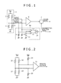
- Fig. 1 is a circuit diagram of the disconnection detection circuit for a bridge circuit of the first embodiment.
- a detection element 1 is formed with a bridge circuit having a series circuit composed of sensor element resistors 2 and 4 and series resistors, which include sensor element resistors 3 and 5, connected in parallel with each other.
- sensor element resistors 2 and 4 vary depending on a measurement physical quantity
- an intermediate voltage between the sensor element resistors 2 and 4 and an intermediate voltage between the sensor element resistors 3 and 5 vary.
- the intermediate voltage between the sensor element resistors 3 and 5 is inputted to an output terminal A, and fetched into outside of the detection element 1 through the output terminal A.
- the intermediate voltage between the sensor element resistors 2 and 4 is inputted to an output terminal B, and fetched into outside of the detection element 1 through the output terminal B.
- An output voltage (a voltage between the output terminals A and B) of the bridge circuit fetched through the output terminal A and output terminal B is amplified by an amplifier 6, and outputted to outside as a sensor output via a switching circuit 7.
- a sensor element resistor for example, platinum (Pt), tantalum (Ta), molybdenum (Mo), or silicon (Si) is selected.
- a disconnection detection circuit 8a includes a resistor 10 that causes a current to flow into the output terminal A, a resistor 9 that causes a current to flow into the output terminal B, a reference voltage source 11 that regenerates a reference voltage, a comparator 12 that compares the voltage at the output terminal A with the voltage at the reference voltage source 11 so as to detect the disconnection of the output terminal A, a comparator 13 that compares the voltage at the output terminal B with the voltage at the reference voltage source 11 so as to detect the disconnection of the output terminal B, and an OR circuit 14 that obtains an OR of the comparator 12 and comparator 13. If the disconnection detection circuit 8a detects a disconnection, the switching circuit 7 fixes the sensor output to a ground voltage or a supply voltage.
- the disconnection detection circuit 8a detects the disconnections of the output terminal A and output terminal B.
- the output terminal A If the output terminal A is disconnected, the potential at the output terminal A is brought to a ground potential by the resistor 10. The potential at the output terminal A is compared with the voltage at the reference voltage source 11 by the comparator 12. When the output terminal A is disconnected, the disconnection is reflected on the output of the comparator 12.
- the output terminal B If the output terminal B is disconnected, the potential at the output terminal B is brought to the ground potential by the resistor 9. The potential at the output terminal B is compared with the voltage at the reference voltage source 11 by the comparator 13. When the output terminal B is disconnected, the disconnection is reflected on the output of the comparator 13.
- the disconnection detection circuit 8 can detect the disconnections of the output terminal A and output terminal B.
- the disconnection detection circuit 8a is a circuit that is symmetrical with respect to the output terminals A and B of the bridge circuit of the detection element 1, whereby an adverse effect on an output voltage of the bridge circuit of the detection element 1 can be minimized.
- a circuit to be connected to the output terminal A includes the resistor 10 and comparator 12, and a circuit to be connected to the output terminal B includes the resistor 9 and comparator 13.
- Fig. 3 is a circuit diagram of the disconnection detection circuit for a bridge circuit of the second embodiment
- Fig. 4 is a diagram showing a drain current characteristic of transistors 24 and 25.
- the disconnection detection circuit for a bridge circuit of the second embodiment is such that the resistors 9 and 10 of the disconnection detection circuit for a bridge circuit of the first embodiment are changed into a current mirror circuit composed of transistors 23, 24, and 25.
- the resistors 9 and 10 are changed into a current mirror circuit composed of the transistors 23, 24, and 25.
- a constant current source 22 is connected to the transistor 23, so that the drain currents of the transistors 24 and 25 exhibit a characteristic shown in Fig. 4 . Accordingly, when the output terminals A and B are not disconnected, the impedances of the transistors 24 and 25 with respect to the output terminals A and B can be raised. Therefore, an adverse effect on the output voltage of the bridge circuit can be further reduced.
- Fig. 5 is a circuit diagram of the disconnection detection circuit for a bridge circuit of the third embodiment
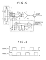
- Fig. 6 is a timing chart of control signals for switches 26, 28, 29, 30, 31, and 32.
- the third embodiment is such that the switches 26, 28, 29, 30, 31, and 32 and capacitors 27, 33, and 34 are added to the first embodiment.
- the switches 26, 28, 29, 30, 31, and 32 and capacitors 27, 33, and 34 are added so that detection of a bridge voltage and disconnection detection can be executed in time-sharing manner. Specifically, at timing P1, the switches 26 and 30 are made in order to connect the output terminals A and B to the amplifier 6, whereby the output voltage of the bridge circuit is detected. At this time, the switches 28 and 29 enter a broken state. Therefore, the disconnection detection circuit 8c does not affect the output voltage of the bridge circuit because the bridge circuit is completely disconnected from the disconnection detection circuit 8c.
- the capacitor 27 is included to hold the voltage at the timing P1 in preparation for the timing P2 when the switches 26 and 30 are broken.
- the switches 28, 29, 31, and 32 are made at the timing P2 in order to connect the output terminals A and B to the disconnection detection circuit 8c, whereby the disconnection of the output terminal A or B of the bridge circuit is detected.
- the switches 26 and 30 are left broken and completely disconnected from the amplifier 6. Therefore, an input resistance of the amplifier 6 does not affect the disconnection detection circuit 8.
- the capacitors 33 and 34 are included to hold the voltages attained at the timing P2 in preparation for the timing P1 when the switches 28, 29, 31, and 32 are broken.
- Fig. 7 is a circuit diagram of the disconnection detection circuit for a bridge circuit of the fourth embodiment.
- a detection element 35 is a half bridge circuit composed of sensor element resistors 36 and 37.
- the sensor element resistors 36 and 37 vary depending on a measurement physical quantity, a voltage at an output terminal of the bridge circuit is varied.
- An output voltage of the half bridge circuit is amplified by an amplifier 39 and outputted to outside as a sensor output.
- a supply voltage Vcc is connected to a power terminal of the bridge circuit, and a predetermined voltage is fed to a ground terminal via a reference voltage source 38.
- a disconnection detection circuit 41 includes a constant current source 42 that feeds a current to the output terminal of the half bridge circuit, a reference voltage source 43 that generates a reference voltage, and a comparator 44 that compares a voltage at the output terminal of the half bridge circuit with the value of the reference voltage source 43 so as to detect the disconnection of the output terminal. If the disconnection detection circuit 41 detects a disconnection, a switching circuit 40 fixes the sensor output to a ground voltage or supply voltage.
- the disconnection detection circuit detects the disconnection of the output terminal of the half bridge circuit. To begin with, if the output terminal is disconnected, the potential at the output terminal is brought to a ground potential by the constant current source 42. The potential at the output terminal is compared with the voltage of the reference voltage source 43 by the comparator 44. Therefore, if the output terminal is disconnected, the disconnection is reflected on the output of the comparator 44. Thus, the disconnection detection circuit 41 detects the disconnection of the output terminal.
- the sensor element resistor 36 is a component whose resistance varies, like a thermistor, by several digits depending on temperature, the voltage at the output terminal changes from near the voltage at the power terminal of the detection element 35 to near the voltage at the ground terminal.
- a voltage at a ground terminal of the detection element 35 a voltage of several volts is applied using the reference voltage source 38.
- the sensor element resistor 36 is a component whose resistance varies, like a thermistor, by several digits depending on temperature
- the voltage at the output terminal changes merely from a voltage at a power terminal of the detection element 35 to the voltage of the reference voltage source 38 that is the voltage at the ground terminal. Therefore, the current of the constant current source 42 can be diminished because it should merely be equal to or lower than the voltage of the reference voltage source 38 at the disconnectiontime of the output terminal of the detection element 35.
- the margin of the threshold for the comparator 44 can be increased. Eventually, precision in disconnection detection can be improved.
- Fig. 8 is a circuit diagram of the disconnection detection circuit for a bridge circuit of the fifth embodiment.
- the disconnection detection circuit for a bridge circuit of the fifth embodiment is, contrary to the disconnection detection circuit for a bridge circuit of the fourth embodiment, such that a voltage at a power terminal of a detection element 35 is dropped by several volts using a reference voltage source 45.
- the detection element 35 is a half bridge circuit composed of sensor element resistors 36 and 37.
- the sensor element resistors 36 and 37 vary depending on a measurement physical quantity, whereby a voltage at an output terminal of the bridge circuit is varied.
- the output voltage of the bridge circuit is amplified by an amplifier 39 and outputted to outside as a sensor output.
- a power terminal of the bridge circuit is connected to a supply voltage Vcc via a reference voltage source 45.
- a voltage that is lower than the supply voltage Vcc by the voltage of the reference voltage source 45 is fed to the power terminal.
- a ground terminal is provided with a ground potential.
- a disconnection detection circuit 46 includes a constant current source 47 that feeds a current into the output terminal, a reference voltage source 48 that generates a reference voltage, and a comparator 49 that compares the voltage at the output terminal with the value of the reference voltage source 48 so as to detect the disconnection of the output terminal. If the disconnection detection circuit 46 detects a disconnection, a switching circuit 40 fixes the sensor output to a ground voltage or supply voltage.
- the disconnection detection circuit detects the disconnection of the output terminal. If the output terminal is disconnected, the potential at the output terminal is brought to the supply voltage by the constant current source 47. The potential at the output terminal is compared with the voltage of the reference voltage source 48 by the comparator 49. Therefore, if the output terminal is disconnected, the disconnection is reflected on the output of the comparator 49. Accordingly, the disconnection detection circuit 46 detects the disconnection of the output terminal.
- the sensor element resistor 36 is, like a thermistor, a component whose resistance value varies by several digits depending on temperature
- the voltage at the output terminal changes from the voltage at the power terminal of the detection element 35 to the voltage at the ground terminal.
- the voltage at the power terminal is equal to the supply voltage Vcc.
- the current of the constant current source 47 is increased, an adverse effect on the sensor output is intensified.
- the voltage of the reference voltage source 48 is set to almost the supply voltage Vcc, a margin of a threshold for the comparator 49 nearly runs out. Therefore, precision in disconnection detection is degraded.
- the reference voltage source 45 is used to drop the voltage at the power terminal of the detection element 35 so that the voltage becomes lower than the supply voltage Vcc by several volts.
- the sensor element resistor 36 is, like a thermistor, a component whose resistance value varies by several digits depending on temperature, the voltage at the output terminal merely changes from a voltage, which is lower by several volts than the supply voltage that is equal to the voltage at the power terminal of the detection element 35, to the ground voltage. Therefore, the current of the constant current source 47 can be diminished because when the output terminal of the detection element 35 is disconnected, the voltage at the power supply should merely approach the supply voltage with a margin equivalent to the voltage of the reference voltage source 45.
- the voltage of the reference voltage source 48 that is a reference value for disconnection detection can be set with a margin equivalent to the voltage of the reference voltage source 45. Therefore, the margin of the threshold for the comparator 49 can be increased. Eventually, precision in disconnection detection can be improved.
- Fig. 9 is a circuit diagram of the disconnection detection circuit for a bridge circuit of the sixth embodiment.
- a detection element 50 is a bridge circuit composed of sensor element resistors 51, 52, 53, and 54.
- the sensor element resistors 51, 52, 53, and 54 vary depending on a measurement physical quantity, whereby voltages at output terminals A and B of the bridge circuit are varied.
- An output voltage of the bridge circuit (a voltage between the output terminals A and B) is analog-to-digital converted by a delta-sigma modulator 55 (hereinafter, a ⁇ modulator), and outputted to outside as a sensor output.
- the ⁇ modulator 55 includes an SC integrator that is composed of switches 56, 58, 63, and 65 which act at the timing P1 shown in Fig.
- a disconnection detection circuit 72 includes a switch 74 that acts at the timing P2 shown in Fig. 6 so as to link the output terminal A and a constant current source 76, a switch 73 that acts at the timing P2 shown in Fig.
- the ⁇ modulator 55 discharges the capacitors 57 and 64 at the timing P2.
- the ⁇ modulator 55 samples the output voltage of the bridge circuit and charges the capacitors using the SC integrator.
- the disconnection detection circuit 72 acts at the timing P2, which is a non-sampling periodof the ⁇ modulator 55, so as not to affect the action of the ⁇ modulator 55.
- the disconnection detection circuit 72 turns on the switches 73, 74, 77, and 78 at the timing P2 so that a constant current flows into the output terminals A and B of the bridge circuit.
- the disconnection detection circuit 72 is a circuit symmetrical with respect to the output terminals A and B of the bridge circuit of the detection element 50, an adverse effect on the output voltage of the bridge circuit of the detection element 50 can be minimized.
- the action of the disconnection detection circuit 72 does not affect the ⁇ modulator 55. In reverse, the action of the ⁇ modulator 55 does not affect the disconnection detection circuit 72.
- ⁇ modulator 55 When the ⁇ modulator 55 is employed in a detection circuit for an output voltage of a bridge circuit, it is very easy to fix an output signal to a value that cannot be outputted as an ordinary sensor output because an AND circuit alone is needed.
- Fig. 10 is a circuit diagram of the disconnection detection circuit for a bridge circuit of the seventh embodiment.
- the present embodiment is such that the constant current sources 75 and 76 of the sixth embodiment are replaced with a switched capacitor circuit composed of switches 85 and 87 and capacitors 86 and 88.
- Fig. 11 is a configuration diagram of the system of the eighth embodiment including the disconnection detecting means.
- the present embodiment includes an airflow sensor 89 that detects an air flow rate Q, an intake air temperature sensor 90 that detects intake air temperature Ta, a disconnection detector 91 that detects the disconnection of the intake air temperature sensor 90, a correction circuit 92 that corrects the air flow rate Q, which is an output signal of the airflow sensor 89, with the intake air temperature Ta that is an output signal of the intake air temperature sensor 90, and a switching circuit 93 that, if the disconnection detector 91 detects a disconnection, fixes the signal of the intake air temperature Ta, which is handed to the correction circuit 92, to 25° C.
- the present embodiment is the system in which if the intake air temperature sensor 90 is disconnected and outputs the signal having an extremely large error, the correction circuit 92 is prevented from performing excess correction processing and outputting a signal, which has an extremely large error, as a sensor output (air flow rate signal).
- the switching circuit 93 fixes the signal of the intake air temperature Ta, which is fed to the correction circuit 92, to 25° C. Thus, excessive correction is prevented. Accordingly, even if the intake air temperature sensor 90 is disconnected, an error in the sensor output can be suppressed.
- Fig. 12 is a configuration diagram of the system of the ninth embodiment including the disconnection detecting means.
- the present embodiment is a system that includes the disconnection detecting means and has the switching circuit 93, which is included in the system of the eighth embodiment including the disconnection detecting means, changed into a switching circuit 94.
- the switching circuit 93 is changed into the switching circuit 94. If the intake air temperature sensor is disconnected, the correction circuit 92 is bypassed in order to prevent excessive correction. Thus, even if the intake air temperature sensor 90 is disconnected, an error in the sensor output can be suppressed.
- Fig. 13 is a configuration diagram of the system of the tenth embodiment including the disconnection detecting means.
- the present embodiment is a system that includes the disconnection detecting means, has a circuit temperature sensor 95 added to the system of the eighth embodiment including the disconnection detecting means, and has a switching destination at a disconnection time by the switching circuit 93 changed to another.
- the circuit temperature sensor 95 is added, and the switching destination at a disconnection time by the switching circuit 93 is changed to another. If the intake air temperature sensor is disconnected, the switching destination of the correction circuit 92 is set to the circuit temperature sensor 95 in order to prevent excessive correction. This is attributable to the fact that in a steady state, there is no large difference between the intake air temperature Ta and circuit temperature Tlsi. Accordingly, even if the intake air temperature sensor 90 is disconnected, an error in the sensor output can be suppressed.
Landscapes
- Physics & Mathematics (AREA)
- General Physics & Mathematics (AREA)
- Electromagnetism (AREA)
- Engineering & Computer Science (AREA)
- General Engineering & Computer Science (AREA)
- Testing Of Short-Circuits, Discontinuities, Leakage, Or Incorrect Line Connections (AREA)
- Transmission And Conversion Of Sensor Element Output (AREA)
- Indication And Recording Devices For Special Purposes And Tariff Metering Devices (AREA)
Abstract
Description
- The present invention relates to a disconnection detection circuit for a bridge circuit, or more particularly, to a disconnection detection circuit for a bridge circuit that little affects an output voltage of a bridge circuit.
- Existing examples of a disconnection detection circuit for a bridge circuit include a sensor bridge circuit described in Japanese Unexamined Patent Application Publication No.
Hei6-249730 - Patent literature 1: Japanese Unexamined Patent Application Publication No.
Hei6-249730 - An existing technology described in Japanese Unexamined Patent Application Publication No.
Hei6-249730 Fig. 2 ,resistors sensor element resistors amplifier 21 is largely varied so that the fact that the bridge circuit has been disconnected can be detected. - However, in the foregoing disconnection detection circuit, consideration is not taken into the fact that since the
resistors - The present invention addresses the foregoing situation. An object of the present invention is to provide a disconnection detection circuit for a bridge circuit which suppresses a change in a characteristic of a sensor to a minimalextent.
- In order to solve the aforesaid problem, a current is caused to flow from an output terminal of a bridge circuit to a predetermined potential, a potential difference between the potential at the output terminal of the bridge circuit and the predetermined potential is detected, and a disconnection is detected based on the potential difference. Advantageous Effects of Invention
- According to the present invention, an adverse effect which a disconnection detection circuit imposes on an output voltage of a sensor bridge circuit can be reduced. Therefore, an offset voltage or temperature characteristic of a sensor bridge output can be improved, and the disconnection of the sensor bridge can be highly precisely detected. Eventually, a highly precise and highly reliable sensor can be provided.
-
-
Fig. 1 is a circuit diagram of a disconnection detection circuit for a bridge circuit of a first embodiment; -
Fig. 2 is a diagram showing a disconnection detection circuit for a bridge circuit of an existing technology; -
Fig. 3 is a circuit diagram of a disconnection detection circuit for a bridge circuit of a second embodiment; -
Fig. 4 is a diagram showing a drain current characteristic oftransistors -
Fig. 5 is a circuit diagram of a disconnection detection circuit for a bridge circuit of a third embodiment; -
Fig. 6 is a timing chart of control signals forswitches -
Fig. 7 is a circuit diagram of a disconnection detection circuit for a bridge circuit of a fourth embodiment; -
Fig. 8 is a circuit diagram of a disconnection detection circuit for a bridge circuit of a fifth embodiment; -
Fig. 9 is a circuit diagram of a disconnection detection circuit for a bridge circuit of a sixth embodiment; -
Fig. 10 is a circuit diagram of a disconnection detection circuit for a bridge circuit of a seventh embodiment; -
Fig. 11 is a configuration diagram of a system of an eighth embodiment including a disconnection detecting means; -
Fig. 12 is a configuration diagram of a system of a ninth embodiment including a disconnection detecting means; and -
Fig. 13 is a configuration diagram of a system of a tenth embodiment including a disconnection detecting means. Description of Embodiments - Now, referring to
Fig. 1 to Fig. 13 , embodiments of the present invention will be described below. - To begin with, a disconnection detection circuit for a bridge circuit that is a first embodiment of the present invention will be described in conjunction with
Fig. 1. Fig. 1 is a circuit diagram of the disconnection detection circuit for a bridge circuit of the first embodiment. - A
detection element 1 is formed with a bridge circuit having a series circuit composed ofsensor element resistors sensor element resistors sensor element resistors sensor element resistors sensor element resistors sensor element resistors detection element 1 through the output terminal A. The intermediate voltage between thesensor element resistors detection element 1 through the output terminal B. An output voltage (a voltage between the output terminals A and B) of the bridge circuit fetched through the output terminal A and output terminal B is amplified by anamplifier 6, and outputted to outside as a sensor output via aswitching circuit 7. For the sensor element resistors, for example, platinum (Pt), tantalum (Ta), molybdenum (Mo), or silicon (Si) is selected. - A
disconnection detection circuit 8a includes aresistor 10 that causes a current to flow into the output terminal A, a resistor 9 that causes a current to flow into the output terminal B, areference voltage source 11 that regenerates a reference voltage, acomparator 12 that compares the voltage at the output terminal A with the voltage at thereference voltage source 11 so as to detect the disconnection of the output terminal A, acomparator 13 that compares the voltage at the output terminal B with the voltage at thereference voltage source 11 so as to detect the disconnection of the output terminal B, and anOR circuit 14 that obtains an OR of thecomparator 12 andcomparator 13. If thedisconnection detection circuit 8a detects a disconnection, theswitching circuit 7 fixes the sensor output to a ground voltage or a supply voltage. - Next, actions of the
disconnection detection circuit 8a will be described. Thedisconnection detection circuit 8a detects the disconnections of the output terminal A and output terminal B. - If the output terminal A is disconnected, the potential at the output terminal A is brought to a ground potential by the
resistor 10. The potential at the output terminal A is compared with the voltage at thereference voltage source 11 by thecomparator 12. When the output terminal A is disconnected, the disconnection is reflected on the output of thecomparator 12. - If the output terminal B is disconnected, the potential at the output terminal B is brought to the ground potential by the resistor 9. The potential at the output terminal B is compared with the voltage at the
reference voltage source 11 by thecomparator 13. When the output terminal B is disconnected, the disconnection is reflected on the output of thecomparator 13. - Therefore, if the output terminal A or output terminal B is disconnected, the disconnection is reflected on the output of the OR circuit that obtains the OR of the outputs of the
comparators - Next, the features of the
disconnection detection circuit 8a of the present embodiment will be described below. Thedisconnection detection circuit 8a is a circuit that is symmetrical with respect to the output terminals A and B of the bridge circuit of thedetection element 1, whereby an adverse effect on an output voltage of the bridge circuit of thedetection element 1 can be minimized. Specifically, a circuit to be connected to the output terminal A includes theresistor 10 andcomparator 12, and a circuit to be connected to the output terminal B includes the resistor 9 andcomparator 13. Thus, since the identical circuits are connected to the respective output terminals, adverse effects which thedisconnection detection circuit 8a imposes on the output terminal A and output terminal B respectively are identical to each other. Accordingly, an adverse effect on the output voltage of the bridge circuit of the detection element 1 (a difference voltage between the output terminal A and output terminal B) can be reduced. - Next, a disconnection detection circuit for a bridge circuit that is a second embodiment of the present invention will be described in conjunction with
Fig. 3 and Fig. 4 . Incidentally,Fig. 3 is a circuit diagram of the disconnection detection circuit for a bridge circuit of the second embodiment, andFig. 4 is a diagram showing a drain current characteristic oftransistors resistors 9 and 10 of the disconnection detection circuit for a bridge circuit of the first embodiment are changed into a current mirror circuit composed oftransistors - In the
disconnection detection circuit 8b for a bridge circuit of the present embodiment, theresistors 9 and 10 are changed into a current mirror circuit composed of thetransistors current source 22 is connected to thetransistor 23, so that the drain currents of thetransistors Fig. 4 . Accordingly, when the output terminals A and B are not disconnected, the impedances of thetransistors - When the disconnection of the output terminal A or output terminal B is detected, the impedance of the
transistor comparator - Next, a disconnection detection circuit for a bridge circuit of a third embodiment of the present invention will be described in conjunction with
Fig. 5 and Fig. 6. Fig. 5 is a circuit diagram of the disconnection detection circuit for a bridge circuit of the third embodiment, andFig. 6 is a timing chart of control signals forswitches switches capacitors - In the present embodiment, the
switches capacitors switches amplifier 6, whereby the output voltage of the bridge circuit is detected. At this time, theswitches disconnection detection circuit 8c does not affect the output voltage of the bridge circuit because the bridge circuit is completely disconnected from thedisconnection detection circuit 8c. Thecapacitor 27 is included to hold the voltage at the timing P1 in preparation for the timing P2 when theswitches - Thereafter, the
switches disconnection detection circuit 8c, whereby the disconnection of the output terminal A or B of the bridge circuit is detected. At this time, theswitches amplifier 6. Therefore, an input resistance of theamplifier 6 does not affect the disconnection detection circuit 8. Thecapacitors 33 and 34 are included to hold the voltages attained at the timing P2 in preparation for the timing P1 when theswitches - Next, a disconnection detection circuit for a bridge circuit that is a fourth embodiment of the present invention will be described in conjunction with
Fig. 7. Fig. 7 is a circuit diagram of the disconnection detection circuit for a bridge circuit of the fourth embodiment. - To begin with, a
detection element 35 is a half bridge circuit composed ofsensor element resistors sensor element resistors amplifier 39 and outputted to outside as a sensor output. A supply voltage Vcc is connected to a power terminal of the bridge circuit, and a predetermined voltage is fed to a ground terminal via areference voltage source 38. Adisconnection detection circuit 41 includes a constantcurrent source 42 that feeds a current to the output terminal of the half bridge circuit, areference voltage source 43 that generates a reference voltage, and acomparator 44 that compares a voltage at the output terminal of the half bridge circuit with the value of thereference voltage source 43 so as to detect the disconnection of the output terminal. If thedisconnection detection circuit 41 detects a disconnection, a switchingcircuit 40 fixes the sensor output to a ground voltage or supply voltage. - Next, actions of the disconnection detection circuit will be described below. The disconnection detection circuit detects the disconnection of the output terminal of the half bridge circuit. To begin with, if the output terminal is disconnected, the potential at the output terminal is brought to a ground potential by the constant
current source 42. The potential at the output terminal is compared with the voltage of thereference voltage source 43 by thecomparator 44. Therefore, if the output terminal is disconnected, the disconnection is reflected on the output of thecomparator 44. Thus, thedisconnection detection circuit 41 detects the disconnection of the output terminal. - Next, the features of the disconnection detection circuit will be described below. Assuming that the
sensor element resistor 36 is a component whose resistance varies, like a thermistor, by several digits depending on temperature, the voltage at the output terminal changes from near the voltage at the power terminal of thedetection element 35 to near the voltage at the ground terminal. - Assuming that the voltage at the ground voltage is 0 V, when the disconnection of the output terminal has to be reliably detected, it is necessary to increase the current of the constant
current source 42 and to set the voltage of thereference voltage source 43 to almost 0 V. This is because, since the output of thedetection element 35 at a normal time changes from near the voltage at the power terminal of thedetection element 35 to near the voltage at the ground terminal, it is necessary to bring the voltage at a disconnection time to a voltage that falls outside the output at the normal time, and to bring the voltage of thereference voltage source 43, which is a voltage to be compared by thecomparator 44, to the voltage that falls outside the output at the normal time. Therefore, in order to reliably bring the voltage at the disconnection time to the voltage that falls outside the output at the normal time, that is, in order to bring the voltage to almost 0 V, it is necessary to increase the current of the constantcurrent source 42 and to bring a comparison voltage of thecomparator 44 to near almost 0 V. However, when the current of the constantcurrent source 42 is increased, an adverse effect on a sensor output is intensified. When the voltage of the reference voltage source is brought to almost 0 V, a margin of a threshold for thecomparator 44 nearly runs out. Eventually, precision in disconnection detection is degraded. - In the present embodiment, as a voltage at a ground terminal of the
detection element 35, a voltage of several volts is applied using thereference voltage source 38. In this case, even if thesensor element resistor 36 is a component whose resistance varies, like a thermistor, by several digits depending on temperature, the voltage at the output terminal changes merely from a voltage at a power terminal of thedetection element 35 to the voltage of thereference voltage source 38 that is the voltage at the ground terminal. Therefore, the current of the constantcurrent source 42 can be diminished because it should merely be equal to or lower than the voltage of thereference voltage source 38 at the disconnectiontime of the output terminal of thedetection element 35. In addition, since the voltage of thereference voltage source 43 that is a reference value for disconnection detection can be set to the voltage of thereference voltage source 38, the margin of the threshold for thecomparator 44 can be increased. Eventually, precision in disconnection detection can be improved. - Next, a disconnection detection circuit for a bridge circuit which is a fifth embodiment of the present invention will be described in conjunction with
Fig. 8. Fig. 8 is a circuit diagram of the disconnection detection circuit for a bridge circuit of the fifth embodiment. Incidentally, the disconnection detection circuit for a bridge circuit of the fifth embodiment is, contrary to the disconnection detection circuit for a bridge circuit of the fourth embodiment, such that a voltage at a power terminal of adetection element 35 is dropped by several volts using areference voltage source 45. - To begin with, the
detection element 35 is a half bridge circuit composed ofsensor element resistors sensor element resistors amplifier 39 and outputted to outside as a sensor output. A power terminal of the bridge circuit is connected to a supply voltage Vcc via areference voltage source 45. A voltage that is lower than the supply voltage Vcc by the voltage of thereference voltage source 45 is fed to the power terminal. A ground terminal is provided with a ground potential. Adisconnection detection circuit 46 includes a constantcurrent source 47 that feeds a current into the output terminal, areference voltage source 48 that generates a reference voltage, and acomparator 49 that compares the voltage at the output terminal with the value of thereference voltage source 48 so as to detect the disconnection of the output terminal. If thedisconnection detection circuit 46 detects a disconnection, a switchingcircuit 40 fixes the sensor output to a ground voltage or supply voltage. - Next, actions of the disconnection detection circuit will be described below. The disconnection detection circuit detects the disconnection of the output terminal. If the output terminal is disconnected, the potential at the output terminal is brought to the supply voltage by the constant
current source 47. The potential at the output terminal is compared with the voltage of thereference voltage source 48 by thecomparator 49. Therefore, if the output terminal is disconnected, the disconnection is reflected on the output of thecomparator 49. Accordingly, thedisconnection detection circuit 46 detects the disconnection of the output terminal. - Next, the features of the disconnection detection circuit will be described below. When the
sensor element resistor 36 is, like a thermistor, a component whose resistance value varies by several digits depending on temperature, the voltage at the output terminal changes from the voltage at the power terminal of thedetection element 35 to the voltage at the ground terminal. Assume that the voltage at the power terminal is equal to the supply voltage Vcc. In this case, for reliably detecting the disconnection of the output terminal, it is necessary to increase the current of the constantcurrent source 47 and to set the voltage of thereference voltage source 48 to almost the supply voltage Vcc. However, when the current of the constantcurrent source 47 is increased, an adverse effect on the sensor output is intensified. When the voltage of thereference voltage source 48 is set to almost the supply voltage Vcc, a margin of a threshold for thecomparator 49 nearly runs out. Therefore, precision in disconnection detection is degraded. - In the present embodiment, the
reference voltage source 45 is used to drop the voltage at the power terminal of thedetection element 35 so that the voltage becomes lower than the supply voltage Vcc by several volts. In this case, even if thesensor element resistor 36 is, like a thermistor, a component whose resistance value varies by several digits depending on temperature, the voltage at the output terminal merely changes from a voltage, which is lower by several volts than the supply voltage that is equal to the voltage at the power terminal of thedetection element 35, to the ground voltage. Therefore, the current of the constantcurrent source 47 can be diminished because when the output terminal of thedetection element 35 is disconnected, the voltage at the power supply should merely approach the supply voltage with a margin equivalent to the voltage of thereference voltage source 45. In addition, the voltage of thereference voltage source 48 that is a reference value for disconnection detection can be set with a margin equivalent to the voltage of thereference voltage source 45. Therefore, the margin of the threshold for thecomparator 49 can be increased. Eventually, precision in disconnection detection can be improved. - Next, a disconnection detection circuit for a bridge circuit that is a sixth embodiment of the present invention will be described below in conjunction with
Fig. 9. Fig. 9 is a circuit diagram of the disconnection detection circuit for a bridge circuit of the sixth embodiment. - To begin with, a
detection element 50 is a bridge circuit composed ofsensor element resistors sensor element resistors ΔΣ modulator 55 includes an SC integrator that is composed ofswitches Fig. 6 , switches 59, 60, 61, and 62 which act at the timing P2 shown inFig. 6 ,capacitors amplifier 67, acomparator 69 that compares the output of the SC integrator, a local digital-to-analog (D/A)converter 70 that outputs a voltage according to the output of thecomparator 69. Adisconnection detection circuit 72 includes aswitch 74 that acts at the timing P2 shown inFig. 6 so as to link the output terminal A and a constantcurrent source 76, aswitch 73 that acts at the timing P2 shown inFig. 6 so as to link the output terminal B and a constantcurrent source 75, the constantcurrent source 76 that feeds a current into the output terminal A, the constantcurrent source 75 that feeds a current into the output terminal B, a sample-and-hold circuit that samples voltages across the constantcurrent sources Fig. 6 and is composed ofswitches capacitors reference voltage source 81 that generates a reference voltage, acomparator 82 that compares a voltage across thecapacitor 79 with the value of thereference voltage source 82 so as to detect the disconnection of the output terminal A, acomparator 83 that compares a voltage across thecapacitor 80 with the value of thereference voltage source 81 so as to detect the disconnection of the output terminal B, and anOR circuit 84 that obtains an OR of thecomparator 82 andcomparator 83. In addition, there is an ANDcircuit 71 that, if thedisconnection detection circuit 72 detects a disconnection, fixes the output of theΔΣ modulator 55 to a ground. - Next, actions of the present embodiment will be described below. The
ΔΣ modulator 55 discharges thecapacitors ΔΣ modulator 55 samples the output voltage of the bridge circuit and charges the capacitors using the SC integrator. Thedisconnection detection circuit 72 acts at the timing P2, which is a non-sampling periodof theΔΣ modulator 55, so as not to affect the action of theΔΣ modulator 55. Thedisconnection detection circuit 72 turns on theswitches current source switches capacitors comparator - Next, the features of the present embodiment will be described below. Since the
disconnection detection circuit 72 is a circuit symmetrical with respect to the output terminals A and B of the bridge circuit of thedetection element 50, an adverse effect on the output voltage of the bridge circuit of thedetection element 50 can be minimized. - Since the
disconnection detection circuit 72 acts during the non-sampling period of theΔΣ modulator 55, the action of thedisconnection detection circuit 72 does not affect theΔΣ modulator 55. In reverse, the action of theΔΣ modulator 55 does not affect thedisconnection detection circuit 72. - When the
ΔΣ modulator 55 is employed in a detection circuit for an output voltage of a bridge circuit, it is very easy to fix an output signal to a value that cannot be outputted as an ordinary sensor output because an AND circuit alone is needed. - Next, a disconnection detection circuit for a bridge circuit that is a seventh embodiment of the present invention will be described in conjunction with
Fig. 10. Fig. 10 is a circuit diagram of the disconnection detection circuit for a bridge circuit of the seventh embodiment. The present embodiment is such that the constantcurrent sources switches capacitors 86 and 88. - In the present embodiment, faster detection than that achieved using the constant
current sources current sources ΔΣ modulator 55. Eventually, precision of theΔΣ modulator 55 and responsiveness thereof can be improved. - Next, a system that is an eighth embodiment of the present invention and includes a disconnection detecting means will be described in conjunction with
Fig. 11. Fig. 11 is a configuration diagram of the system of the eighth embodiment including the disconnection detecting means. - The present embodiment includes an
airflow sensor 89 that detects an air flow rate Q, an intakeair temperature sensor 90 that detects intake air temperature Ta, adisconnection detector 91 that detects the disconnection of the intakeair temperature sensor 90, acorrection circuit 92 that corrects the air flow rate Q, which is an output signal of theairflow sensor 89, with the intake air temperature Ta that is an output signal of the intakeair temperature sensor 90, and aswitching circuit 93 that, if thedisconnection detector 91 detects a disconnection, fixes the signal of the intake air temperature Ta, which is handed to thecorrection circuit 92, to 25° C. - The present embodiment is the system in whichif the intake
air temperature sensor 90 is disconnected and outputs the signal having an extremely large error, thecorrection circuit 92 is prevented from performing excess correction processing and outputting a signal, which has an extremely large error, as a sensor output (air flow rate signal). In the present embodiment, if the intakeair temperature sensor 90 is disconnected, the switchingcircuit 93 fixes the signal of the intake air temperature Ta, which is fed to thecorrection circuit 92, to 25° C. Thus, excessive correction is prevented. Accordingly, even if the intakeair temperature sensor 90 is disconnected, an error in the sensor output can be suppressed. In particular, as far as an airflow sensor that measures an intake air flow rate of an automobile is concerned, if an error caused by the airflow sensor is large, a fatal phenomenon that an engine is not started takes place. In particular, such an event must be avoided that although theairflow sensor 89 does not fail, the sensor output becomes extremely abnormal because of the failure of the intakeair temperature sensor 90. The present system can avoid the event. - Next, a system that is a ninth embodiment of the present invention and includes a disconnection detecting means will be described in conjunction with
Fig. 12. Fig. 12 is a configuration diagram of the system of the ninth embodiment including the disconnection detecting means. The present embodiment is a system that includes the disconnection detecting means and has the switchingcircuit 93, which is included in the system of the eighth embodiment including the disconnection detecting means, changed into a switchingcircuit 94. - In the present embodiment, the switching
circuit 93 is changed into the switchingcircuit 94. If the intake air temperature sensor is disconnected, thecorrection circuit 92 is bypassed in order to prevent excessive correction. Thus, even if the intakeair temperature sensor 90 is disconnected, an error in the sensor output can be suppressed. - Next, a system that is a tenth embodiment of the present invention and includes a disconnection detecting means will be described in conjunction with
Fig. 13. Fig. 13 is a configuration diagram of the system of the tenth embodiment including the disconnection detecting means. The present embodiment is a system that includes the disconnection detecting means, has acircuit temperature sensor 95 added to the system of the eighth embodiment including the disconnection detecting means, and has a switching destination at a disconnection time by the switchingcircuit 93 changed to another. - In the present embodiment, the
circuit temperature sensor 95 is added, and the switching destination at a disconnection time by the switchingcircuit 93 is changed to another. If the intake air temperature sensor is disconnected, the switching destination of thecorrection circuit 92 is set to thecircuit temperature sensor 95 in order to prevent excessive correction. This is attributable to the fact that in a steady state, there is no large difference between the intake air temperature Ta and circuit temperature Tlsi. Accordingly, even if the intakeair temperature sensor 90 is disconnected, an error in the sensor output can be suppressed. -
- 1, 35, 50: detection element
- 2, 3, 4, 5, 15, 16, 17, 18, 36, 37, 51, 52, 53, 54: sensor element resistor
- 6, 21, 39, 67: amplifier
- 7, 40, 93, 94: switching circuit
- 8, 8a, 8b, 8c, 41, 46: disconnection detection circuit
- 9, 10, 19, 20: resistor
- 11, 38, 43, 45, 58, 81: reference voltage source
- 12, 13, 44, 49, 69, 82, 83: comparator
- 14, 84: OR circuit
- 22, 42, 47, 75, 76: constant current source
- 23, 24, 25: transistor
- 26, 28, 29, 30, 31, 32, 56, 58, 59, 60, 61, 62, 63, 65, 73, 74, 77, 78, 85, 87: switch
- 27, 33, 34, 57, 64, 66, 68, 79, 80, 86, 88: capacitor
- 55: ΔΣ modulator
- 70: local D/A converter
- 71: AND circuit
- 72: disconnection detection circuit
- 89: airflow sensor
- 90: intake air temperature sensor
- 91: disconnection detector
- 92: correction circuit
Claims (21)
- A disconnection detection circuit for a bridge circuit, comprising:a sensor element resistor whose resistance value varies depending on a physical quantity;a bridge circuit composed ofa plurality of resistors including the sensor element resistor;an output terminal through which an intermediate voltage of the bridge circuit is fetched into outside; anda bridge output detection circuit that detects the intermediate voltage fetched through the output terminal,the disconnection detection circuit for a bridge circuit being connected to the output terminal, characterized in thatthe disconnection detection circuit comprisesa conducting means that causes a current to flow from the output terminal of the bridge circuit to a predetermined potential;a potential difference detection means that detects a potential difference between the potential at the output terminal of the bridge circuit and the predetermined potential; anda disconnection detecting means that detects a disconnection on the basis of the output of the potential difference detection means.
- The disconnection detection circuit for a bridge circuit according toclaim 1, characterized in that:the disconnection detection circuit comprises a switching means that, when the disconnection detecting means detects a disconnection, fixes the output of the bridge output detection circuit to a supply voltage or ground voltage.
- The disconnection detection circuit for a bridge circuit according toeither claim 1 or claim 2, characterized in that the conducting means is connected to the output terminal.
- The disconnection detection circuit for a bridge circuit according toclaim 3, characterized in that a selection switch is included between the output terminal and conducting means and between the output terminal and bridge output detection circuit.
- The disconnection detection circuit for a bridge circuit according toclaim 4, characterized in that the selection switch performs a switching action at the timing when the bridge output detection circuit and conducting means are alternately switched.
- The disconnection detection circuit for a bridge circuit according to Claim 3, characterized in that the voltage at a power terminal of the bridge circuit is a low potential with respect to the predetermined potential of the conducting means.
- The disconnection detection circuit for a bridge circuit according toclaim 3, characterized in that the voltage at a ground terminal of the bridge circuit is a high potential with respect to the predetermined potential of the conducting means.
- The disconnection detection circuit for a bridge circuit according toclaim 3, characterized in that the conducting means is formed with a resistor.
- The disconnection detection circuit for a bridge circuit according toclaim 3, characterized in that the conducting means is formed with a current mirror circuit.
- The disconnection detection circuit for a bridge circuit according toclaim 3, characterized in that the conducting means is formed with a switched capacitor circuit.
- The disconnection detection circuit for a bridge circuit according toclaim 1, characterized in that the bridge output detection circuit is a delta-sigma modulator.
- The disconnection detection circuit for a bridge circuit according toclaim 11, characterized in that the disconnection detection circuit comprises a means that, when the disconnection detecting means detects a disconnection, fixes the output of the delta-sigma modulator to a high level or low level.
- The disconnection detection circuit for a bridge circuit according toclaim 11, characterized in that the output terminal of the bridge circuit is switched to the conducting means during a non-sampling period of the delta-sigma modulator.
- A physical quantity detection system including a first sensor that outputs a signal according to a first physical quantity, a second sensor that outputs a signal according to a second physical quantity, a correcting means that corrects a first sensor characteristic according to the output of the second sensor, and a disconnection detecting means that detects the disconnection of the second sensor, characterized in that:the physical quantity detection system comprises a changing means that, when the disconnection detecting means detects the disconnection, changes the action of the correcting means to another.
- The physical quantity detection system according toclaim 14, characterized in that the disconnection detecting means is the disconnection detection circuit set forth in claims 1 to 12.
- The physical quantity detection system according toclaim 15, characterized in that:when the disconnection detecting means detects the disconnection, the changing means fixes the output signal of the second sensor to a predetermined value and inputs the value to the correcting means.
- The physical quantity detection system according toclaim 15, characterized in that:when the disconnection detecting means detects the disconnection, the changing means switches the output signal of the second sensor to a signal of a third sensor and inputs the signal of the third sensor to the correcting means.
- The physical quantity detection system according toclaim 15, characterized in that:when the disconnection detecting means detects the disconnection, the changing means ceases the action of the correcting means.
- The physical quantity detection system according toclaim 14, characterized in that the first sensor is a sensor that detects an air flow rate.
- The physical quantity detection system according toclaim 14, characterized in that the second sensor is a sensor that detects an air temperature.
- The physical quantity detection system according to claim 17, characterized in that the third sensor is a sensor that detects a circuit temperature.
Applications Claiming Priority (2)
| Application Number | Priority Date | Filing Date | Title |
|---|---|---|---|
| JP2010144413A JP5517777B2 (en) | 2010-06-25 | 2010-06-25 | System having disconnection detection circuit and disconnection detection means for bridge circuit |
| PCT/JP2011/064137 WO2011162240A1 (en) | 2010-06-25 | 2011-06-21 | Circuit for detecting disconnection of bridge circuit and system having means for detecting disconnection |
Publications (3)
| Publication Number | Publication Date |
|---|---|
| EP2587270A1 true EP2587270A1 (en) | 2013-05-01 |
| EP2587270A4 EP2587270A4 (en) | 2018-04-18 |
| EP2587270B1 EP2587270B1 (en) | 2021-08-18 |
Family
ID=45371423
Family Applications (1)
| Application Number | Title | Priority Date | Filing Date |
|---|---|---|---|
| EP11798124.1A Active EP2587270B1 (en) | 2010-06-25 | 2011-06-21 | Circuit for detecting disconnection of bridge circuit |
Country Status (5)
| Country | Link |
|---|---|
| US (1) | US9229040B2 (en) |
| EP (1) | EP2587270B1 (en) |
| JP (1) | JP5517777B2 (en) |
| CN (1) | CN102959411B (en) |
| WO (1) | WO2011162240A1 (en) |
Cited By (3)
| Publication number | Priority date | Publication date | Assignee | Title |
|---|---|---|---|---|
| JP2015118068A (en) * | 2013-12-20 | 2015-06-25 | 株式会社ノーリツ | Analog signal input circuit |
| GB2523890B (en) * | 2014-01-17 | 2018-06-06 | Hamilton Sundstrand Corp | Strain gauge pressure sensor circuit with sensor disconnect detection |
| EP4056957B1 (en) | 2021-03-10 | 2024-10-16 | Honeywell International Inc. | Offset calibration and diagnostics for resistance-based bridge circuits |
Families Citing this family (18)
| Publication number | Priority date | Publication date | Assignee | Title |
|---|---|---|---|---|
| JP5768016B2 (en) | 2012-07-25 | 2015-08-26 | 日立オートモティブシステムズ株式会社 | Sensor device |
| US20140071592A1 (en) * | 2012-09-10 | 2014-03-13 | Electric Power Research Institute, Inc. | Apparatus and method for monitoring substation disconnects and transmission line switches |
| KR101381533B1 (en) | 2012-10-30 | 2014-04-04 | 엘에스산전 주식회사 | Apparatus for detecting wire disconnection |
| JP5851973B2 (en) * | 2012-11-02 | 2016-02-03 | 日立オートモティブシステムズ株式会社 | Thermal flow meter |
| JP6012515B2 (en) * | 2013-03-15 | 2016-10-25 | 日立オートモティブシステムズ株式会社 | Gas sensor |
| EP2787331B1 (en) | 2013-04-01 | 2018-12-26 | ams AG | Sensor arrangement for light sensing and temperature sensing and method for light sensing and temperature sensing |
| CN103471737A (en) * | 2013-09-02 | 2013-12-25 | 深圳市大族激光科技股份有限公司 | Thermocouple temperature detection system |
| JP6450223B2 (en) * | 2015-03-06 | 2019-01-09 | エイブリック株式会社 | Sensor device and inspection method thereof |
| CN104793096A (en) * | 2015-04-07 | 2015-07-22 | 上海新时达电气股份有限公司 | Working state detection circuit of electronic device |
| JP6603695B2 (en) * | 2017-09-15 | 2019-11-06 | 矢崎総業株式会社 | Anomaly detection device |
| KR102443076B1 (en) * | 2017-09-29 | 2022-09-14 | 주식회사 만도 | Vehicle, electronic control unit and method of controlling the electronic control unit |
| JP6909764B2 (en) | 2018-08-24 | 2021-07-28 | 日立Astemo株式会社 | Flow sensor |
| CN109781292A (en) * | 2019-01-31 | 2019-05-21 | 大禹电气科技股份有限公司 | Three-wire system platinum resistance thermometer sensor, break detection circuit and detection device and detection method |
| JP7542982B2 (en) | 2020-04-09 | 2024-09-02 | ミネベアミツミ株式会社 | Fault detection circuit and detection system |
| CN113009313B (en) * | 2021-01-29 | 2022-05-27 | 南京英锐创电子科技有限公司 | Sensor diagnostic device and sensor detection circuit |
| CN115574854B (en) * | 2022-12-05 | 2023-04-11 | 泉州昆泰芯微电子科技有限公司 | Fault diagnosis circuit device, diagnosis method, computer, storage medium and program |
| DE102022132636B3 (en) | 2022-12-08 | 2024-06-13 | Cariad Se | Diagnosis of a connection of an ohmic consumer of a motor vehicle |
| JP2025160783A (en) * | 2024-04-10 | 2025-10-23 | 株式会社デンソー | Voltage Detection Circuit |
Family Cites Families (24)
| Publication number | Priority date | Publication date | Assignee | Title |
|---|---|---|---|---|
| US5279164A (en) * | 1990-12-18 | 1994-01-18 | Mitsubishi Denki Kabushiki Kaisha | Semiconductor pressure sensor with improved temperature compensation |
| JP2538185Y2 (en) * | 1991-03-06 | 1997-06-11 | 日本電気ホームエレクトロニクス株式会社 | Diagnostic circuit for semiconductor acceleration sensor |
| EP0592205B1 (en) * | 1992-10-07 | 1998-01-07 | Nec Corporation | Semiconductor sensor with fault detecting circuit |
| JPH081390B2 (en) * | 1992-10-07 | 1996-01-10 | 日本電気株式会社 | Semiconductor sensor device with failure detection circuit |
| JP3373603B2 (en) | 1992-12-30 | 2003-02-04 | 北陸電気工業株式会社 | Bridge circuit for sensor |
| JP3020771B2 (en) * | 1993-07-08 | 2000-03-15 | 株式会社東芝 | Plant control device |
| JP3410901B2 (en) * | 1996-05-20 | 2003-05-26 | 株式会社東芝 | Amplifier circuit |
| JP3575573B2 (en) * | 1996-08-28 | 2004-10-13 | 株式会社デンソー | Thermal air flow meter |
| JP3478994B2 (en) * | 1999-05-31 | 2003-12-15 | 株式会社日立製作所 | Sensor device |
| US6422088B1 (en) * | 1999-09-24 | 2002-07-23 | Denso Corporation | Sensor failure or abnormality detecting system incorporated in a physical or dynamic quantity detecting apparatus |
| JP2003065876A (en) * | 2001-08-21 | 2003-03-05 | Showa Corp | Abnormality detection device for torque sensor |
| JP2003254850A (en) * | 2002-03-01 | 2003-09-10 | Denso Corp | Sensor output processing circuit with self-diagnosis function |
| JP4041863B2 (en) * | 2002-08-29 | 2008-02-06 | 東京瓦斯株式会社 | Integrated flow meter |
| JP4309668B2 (en) * | 2003-01-24 | 2009-08-05 | 株式会社日立製作所 | Thermal air flow measuring device and diagnostic method thereof |
| US6949977B2 (en) * | 2003-06-26 | 2005-09-27 | Siemens Medical Solutions, Usa | Circuit arrangement having a transimpedance amplifier connected to a current limiter circuit |
| JP4405242B2 (en) * | 2003-11-20 | 2010-01-27 | NEC Avio赤外線テクノロジー株式会社 | Sensor abnormality detection device and sensor abnormality detection method |
| JP4842614B2 (en) * | 2005-10-27 | 2011-12-21 | ルネサスエレクトロニクス株式会社 | Current detection circuit |
| JP4749132B2 (en) * | 2005-11-21 | 2011-08-17 | 富士通セミコンダクター株式会社 | Sensor detection device and sensor |
| JP5138962B2 (en) * | 2007-03-28 | 2013-02-06 | 株式会社ミツバ | Motor control method and motor control apparatus |
| JP2009150655A (en) * | 2007-12-18 | 2009-07-09 | Advics Co Ltd | Vehicle behavior sensor temperature compensating apparatus |
| JP4814209B2 (en) * | 2007-12-21 | 2011-11-16 | オンセミコンダクター・トレーディング・リミテッド | AD converter |
| JP2009276212A (en) * | 2008-05-15 | 2009-11-26 | Advics Co Ltd | Vehicle momentum sensor |
| JP5024259B2 (en) * | 2008-09-30 | 2012-09-12 | 株式会社デンソー | Sensor device and sensor device self-diagnosis method |
| JP5278114B2 (en) * | 2009-03-31 | 2013-09-04 | 株式会社デンソー | Sensor device |
-
2010
- 2010-06-25 JP JP2010144413A patent/JP5517777B2/en active Active
-
2011
- 2011-06-21 CN CN201180030636.5A patent/CN102959411B/en active Active
- 2011-06-21 EP EP11798124.1A patent/EP2587270B1/en active Active
- 2011-06-21 US US13/806,827 patent/US9229040B2/en active Active
- 2011-06-21 WO PCT/JP2011/064137 patent/WO2011162240A1/en not_active Ceased
Non-Patent Citations (1)
| Title |
|---|
| See references of WO2011162240A1 * |
Cited By (3)
| Publication number | Priority date | Publication date | Assignee | Title |
|---|---|---|---|---|
| JP2015118068A (en) * | 2013-12-20 | 2015-06-25 | 株式会社ノーリツ | Analog signal input circuit |
| GB2523890B (en) * | 2014-01-17 | 2018-06-06 | Hamilton Sundstrand Corp | Strain gauge pressure sensor circuit with sensor disconnect detection |
| EP4056957B1 (en) | 2021-03-10 | 2024-10-16 | Honeywell International Inc. | Offset calibration and diagnostics for resistance-based bridge circuits |
Also Published As
| Publication number | Publication date |
|---|---|
| JP2012008014A (en) | 2012-01-12 |
| CN102959411B (en) | 2015-06-24 |
| JP5517777B2 (en) | 2014-06-11 |
| WO2011162240A1 (en) | 2011-12-29 |
| CN102959411A (en) | 2013-03-06 |
| US20130093432A1 (en) | 2013-04-18 |
| US9229040B2 (en) | 2016-01-05 |
| EP2587270B1 (en) | 2021-08-18 |
| EP2587270A4 (en) | 2018-04-18 |
Similar Documents
| Publication | Publication Date | Title |
|---|---|---|
| US9229040B2 (en) | Disconnection detection circuit for bridge circuit and system including disconnection detecting means | |
| US10983187B2 (en) | Measuring bridge arrangement with improved error detection | |
| US8836375B2 (en) | Continuously self-calibrated latched comparator | |
| US11079413B2 (en) | Methods and related systems of a readout circuit for use with a wheatstone bridge sensor | |
| US8029187B2 (en) | Apparatus, system and method for high resolution identification with temperature dependent resistive device | |
| US9128127B2 (en) | Sensor device | |
| CN110928348B (en) | Voltage regulator and test method of voltage regulator | |
| KR101445424B1 (en) | Detection circuit and sensor device | |
| US20190242759A1 (en) | Thermistor drive circuit | |
| US20150115942A1 (en) | Magnetic sensor circuit | |
| US11979120B2 (en) | Amplifier circuitry and current sensor having the same | |
| JP5024259B2 (en) | Sensor device and sensor device self-diagnosis method | |
| CN107228967A (en) | Current detection circuit | |
| US9837997B2 (en) | Comparison circuit and sensor device | |
| JP2012169712A (en) | Charge amplifier | |
| US11828636B2 (en) | Flow rate sensor | |
| US9817034B2 (en) | Measuring device | |
| CN109564139B (en) | Sensor device | |
| US10715114B1 (en) | Filter and operating method thereof | |
| CN117614396A (en) | Current sensing amplifier circuit and input offset voltage correction method | |
| US20140240042A1 (en) | Operational amplifier | |
| CN113728553B (en) | Methods for accurately detecting signals, such as those from sensors. | |
| EP3130894B1 (en) | Abnormality detection device for sensor and sensor device | |
| JP5370915B2 (en) | Voltage limiting circuit | |
| JP4650011B2 (en) | Comparator circuit |
Legal Events
| Date | Code | Title | Description |
|---|---|---|---|
| PUAI | Public reference made under article 153(3) epc to a published international application that has entered the european phase |
Free format text: ORIGINAL CODE: 0009012 |
|
| 17P | Request for examination filed |
Effective date: 20130125 |
|
| AK | Designated contracting states |
Kind code of ref document: A1 Designated state(s): AL AT BE BG CH CY CZ DE DK EE ES FI FR GB GR HR HU IE IS IT LI LT LU LV MC MK MT NL NO PL PT RO RS SE SI SK SM TR |
|
| DAX | Request for extension of the european patent (deleted) | ||
| RIC1 | Information provided on ipc code assigned before grant |
Ipc: G01K 7/24 20060101ALI20171123BHEP Ipc: G01R 31/28 20060101ALI20171123BHEP Ipc: G01D 3/028 20060101ALI20171123BHEP Ipc: G01D 3/08 20060101ALI20171123BHEP Ipc: G01R 31/02 20060101AFI20171123BHEP |
|
| RA4 | Supplementary search report drawn up and despatched (corrected) |
Effective date: 20180319 |
|
| RIC1 | Information provided on ipc code assigned before grant |
Ipc: G01D 3/028 20060101ALI20180313BHEP Ipc: G01R 31/02 20060101AFI20180313BHEP Ipc: G01D 3/08 20060101ALI20180313BHEP Ipc: G01K 7/24 20060101ALI20180313BHEP Ipc: G01R 31/28 20060101ALI20180313BHEP |
|
| REG | Reference to a national code |
Ref country code: DE Ref legal event code: R079 Ref document number: 602011071599 Country of ref document: DE Free format text: PREVIOUS MAIN CLASS: G01R0031020000 Ipc: G01R0031500000 |
|
| GRAP | Despatch of communication of intention to grant a patent |
Free format text: ORIGINAL CODE: EPIDOSNIGR1 |
|
| STAA | Information on the status of an ep patent application or granted ep patent |
Free format text: STATUS: GRANT OF PATENT IS INTENDED |
|
| RIC1 | Information provided on ipc code assigned before grant |
Ipc: G01R 31/50 20200101AFI20210323BHEP |
|
| INTG | Intention to grant announced |
Effective date: 20210415 |
|
| GRAS | Grant fee paid |
Free format text: ORIGINAL CODE: EPIDOSNIGR3 |
|
| GRAA | (expected) grant |
Free format text: ORIGINAL CODE: 0009210 |
|
| STAA | Information on the status of an ep patent application or granted ep patent |
Free format text: STATUS: THE PATENT HAS BEEN GRANTED |
|
| AK | Designated contracting states |
Kind code of ref document: B1 Designated state(s): AL AT BE BG CH CY CZ DE DK EE ES FI FR GB GR HR HU IE IS IT LI LT LU LV MC MK MT NL NO PL PT RO RS SE SI SK SM TR |
|
| REG | Reference to a national code |
Ref country code: GB Ref legal event code: FG4D |
|
| REG | Reference to a national code |
Ref country code: CH Ref legal event code: EP |
|
| REG | Reference to a national code |
Ref country code: DE Ref legal event code: R096 Ref document number: 602011071599 Country of ref document: DE |
|
| REG | Reference to a national code |
Ref country code: AT Ref legal event code: REF Ref document number: 1422116 Country of ref document: AT Kind code of ref document: T Effective date: 20210915 Ref country code: IE Ref legal event code: FG4D |
|
| RAP4 | Party data changed (patent owner data changed or rights of a patent transferred) |
Owner name: HITACHI ASTEMO, LTD. |
|
| REG | Reference to a national code |
Ref country code: DE Ref legal event code: R081 Ref document number: 602011071599 Country of ref document: DE Owner name: HITACHI ASTEMO, LTD., HITACHINAKA-SHI, JP Free format text: FORMER OWNER: HITACHI AUTOMOTIVE SYSTEMS, LTD., HITACHINAKA-SHI, IBARAKI, JP |
|
| REG | Reference to a national code |
Ref country code: LT Ref legal event code: MG9D |
|
| REG | Reference to a national code |
Ref country code: NL Ref legal event code: MP Effective date: 20210818 |
|
| REG | Reference to a national code |
Ref country code: AT Ref legal event code: MK05 Ref document number: 1422116 Country of ref document: AT Kind code of ref document: T Effective date: 20210818 |
|
| PG25 | Lapsed in a contracting state [announced via postgrant information from national office to epo] |
Ref country code: SE Free format text: LAPSE BECAUSE OF FAILURE TO SUBMIT A TRANSLATION OF THE DESCRIPTION OR TO PAY THE FEE WITHIN THE PRESCRIBED TIME-LIMIT Effective date: 20210818 Ref country code: HR Free format text: LAPSE BECAUSE OF FAILURE TO SUBMIT A TRANSLATION OF THE DESCRIPTION OR TO PAY THE FEE WITHIN THE PRESCRIBED TIME-LIMIT Effective date: 20210818 Ref country code: RS Free format text: LAPSE BECAUSE OF FAILURE TO SUBMIT A TRANSLATION OF THE DESCRIPTION OR TO PAY THE FEE WITHIN THE PRESCRIBED TIME-LIMIT Effective date: 20210818 Ref country code: PT Free format text: LAPSE BECAUSE OF FAILURE TO SUBMIT A TRANSLATION OF THE DESCRIPTION OR TO PAY THE FEE WITHIN THE PRESCRIBED TIME-LIMIT Effective date: 20211220 Ref country code: NO Free format text: LAPSE BECAUSE OF FAILURE TO SUBMIT A TRANSLATION OF THE DESCRIPTION OR TO PAY THE FEE WITHIN THE PRESCRIBED TIME-LIMIT Effective date: 20211118 Ref country code: FI Free format text: LAPSE BECAUSE OF FAILURE TO SUBMIT A TRANSLATION OF THE DESCRIPTION OR TO PAY THE FEE WITHIN THE PRESCRIBED TIME-LIMIT Effective date: 20210818 Ref country code: ES Free format text: LAPSE BECAUSE OF FAILURE TO SUBMIT A TRANSLATION OF THE DESCRIPTION OR TO PAY THE FEE WITHIN THE PRESCRIBED TIME-LIMIT Effective date: 20210818 Ref country code: AT Free format text: LAPSE BECAUSE OF FAILURE TO SUBMIT A TRANSLATION OF THE DESCRIPTION OR TO PAY THE FEE WITHIN THE PRESCRIBED TIME-LIMIT Effective date: 20210818 Ref country code: BG Free format text: LAPSE BECAUSE OF FAILURE TO SUBMIT A TRANSLATION OF THE DESCRIPTION OR TO PAY THE FEE WITHIN THE PRESCRIBED TIME-LIMIT Effective date: 20211118 Ref country code: LT Free format text: LAPSE BECAUSE OF FAILURE TO SUBMIT A TRANSLATION OF THE DESCRIPTION OR TO PAY THE FEE WITHIN THE PRESCRIBED TIME-LIMIT Effective date: 20210818 |
|
| PG25 | Lapsed in a contracting state [announced via postgrant information from national office to epo] |
Ref country code: PL Free format text: LAPSE BECAUSE OF FAILURE TO SUBMIT A TRANSLATION OF THE DESCRIPTION OR TO PAY THE FEE WITHIN THE PRESCRIBED TIME-LIMIT Effective date: 20210818 Ref country code: LV Free format text: LAPSE BECAUSE OF FAILURE TO SUBMIT A TRANSLATION OF THE DESCRIPTION OR TO PAY THE FEE WITHIN THE PRESCRIBED TIME-LIMIT Effective date: 20210818 Ref country code: GR Free format text: LAPSE BECAUSE OF FAILURE TO SUBMIT A TRANSLATION OF THE DESCRIPTION OR TO PAY THE FEE WITHIN THE PRESCRIBED TIME-LIMIT Effective date: 20211119 |
|
| PG25 | Lapsed in a contracting state [announced via postgrant information from national office to epo] |
Ref country code: NL Free format text: LAPSE BECAUSE OF FAILURE TO SUBMIT A TRANSLATION OF THE DESCRIPTION OR TO PAY THE FEE WITHIN THE PRESCRIBED TIME-LIMIT Effective date: 20210818 |
|
| PG25 | Lapsed in a contracting state [announced via postgrant information from national office to epo] |
Ref country code: DK Free format text: LAPSE BECAUSE OF FAILURE TO SUBMIT A TRANSLATION OF THE DESCRIPTION OR TO PAY THE FEE WITHIN THE PRESCRIBED TIME-LIMIT Effective date: 20210818 |
|
| REG | Reference to a national code |
Ref country code: DE Ref legal event code: R097 Ref document number: 602011071599 Country of ref document: DE |
|
| PG25 | Lapsed in a contracting state [announced via postgrant information from national office to epo] |
Ref country code: SM Free format text: LAPSE BECAUSE OF FAILURE TO SUBMIT A TRANSLATION OF THE DESCRIPTION OR TO PAY THE FEE WITHIN THE PRESCRIBED TIME-LIMIT Effective date: 20210818 Ref country code: SK Free format text: LAPSE BECAUSE OF FAILURE TO SUBMIT A TRANSLATION OF THE DESCRIPTION OR TO PAY THE FEE WITHIN THE PRESCRIBED TIME-LIMIT Effective date: 20210818 Ref country code: RO Free format text: LAPSE BECAUSE OF FAILURE TO SUBMIT A TRANSLATION OF THE DESCRIPTION OR TO PAY THE FEE WITHIN THE PRESCRIBED TIME-LIMIT Effective date: 20210818 Ref country code: EE Free format text: LAPSE BECAUSE OF FAILURE TO SUBMIT A TRANSLATION OF THE DESCRIPTION OR TO PAY THE FEE WITHIN THE PRESCRIBED TIME-LIMIT Effective date: 20210818 Ref country code: CZ Free format text: LAPSE BECAUSE OF FAILURE TO SUBMIT A TRANSLATION OF THE DESCRIPTION OR TO PAY THE FEE WITHIN THE PRESCRIBED TIME-LIMIT Effective date: 20210818 Ref country code: AL Free format text: LAPSE BECAUSE OF FAILURE TO SUBMIT A TRANSLATION OF THE DESCRIPTION OR TO PAY THE FEE WITHIN THE PRESCRIBED TIME-LIMIT Effective date: 20210818 |
|
| PLBE | No opposition filed within time limit |
Free format text: ORIGINAL CODE: 0009261 |
|
| STAA | Information on the status of an ep patent application or granted ep patent |
Free format text: STATUS: NO OPPOSITION FILED WITHIN TIME LIMIT |
|
| 26N | No opposition filed |
Effective date: 20220519 |
|
| PG25 | Lapsed in a contracting state [announced via postgrant information from national office to epo] |
Ref country code: IT Free format text: LAPSE BECAUSE OF FAILURE TO SUBMIT A TRANSLATION OF THE DESCRIPTION OR TO PAY THE FEE WITHIN THE PRESCRIBED TIME-LIMIT Effective date: 20210818 |
|
| PG25 | Lapsed in a contracting state [announced via postgrant information from national office to epo] |
Ref country code: SI Free format text: LAPSE BECAUSE OF FAILURE TO SUBMIT A TRANSLATION OF THE DESCRIPTION OR TO PAY THE FEE WITHIN THE PRESCRIBED TIME-LIMIT Effective date: 20210818 |
|
| PG25 | Lapsed in a contracting state [announced via postgrant information from national office to epo] |
Ref country code: MC Free format text: LAPSE BECAUSE OF FAILURE TO SUBMIT A TRANSLATION OF THE DESCRIPTION OR TO PAY THE FEE WITHIN THE PRESCRIBED TIME-LIMIT Effective date: 20210818 |
|
| REG | Reference to a national code |
Ref country code: CH Ref legal event code: PL |
|
| REG | Reference to a national code |
Ref country code: BE Ref legal event code: MM Effective date: 20220630 |
|
| GBPC | Gb: european patent ceased through non-payment of renewal fee |
Effective date: 20220621 |
|
| PG25 | Lapsed in a contracting state [announced via postgrant information from national office to epo] |
Ref country code: LU Free format text: LAPSE BECAUSE OF NON-PAYMENT OF DUE FEES Effective date: 20220621 Ref country code: LI Free format text: LAPSE BECAUSE OF NON-PAYMENT OF DUE FEES Effective date: 20220630 Ref country code: IE Free format text: LAPSE BECAUSE OF NON-PAYMENT OF DUE FEES Effective date: 20220621 Ref country code: FR Free format text: LAPSE BECAUSE OF NON-PAYMENT OF DUE FEES Effective date: 20220630 Ref country code: CH Free format text: LAPSE BECAUSE OF NON-PAYMENT OF DUE FEES Effective date: 20220630 |
|
| PG25 | Lapsed in a contracting state [announced via postgrant information from national office to epo] |
Ref country code: GB Free format text: LAPSE BECAUSE OF NON-PAYMENT OF DUE FEES Effective date: 20220621 Ref country code: BE Free format text: LAPSE BECAUSE OF NON-PAYMENT OF DUE FEES Effective date: 20220630 |
|
| PG25 | Lapsed in a contracting state [announced via postgrant information from national office to epo] |
Ref country code: HU Free format text: LAPSE BECAUSE OF FAILURE TO SUBMIT A TRANSLATION OF THE DESCRIPTION OR TO PAY THE FEE WITHIN THE PRESCRIBED TIME-LIMIT; INVALID AB INITIO Effective date: 20110621 |
|
| PG25 | Lapsed in a contracting state [announced via postgrant information from national office to epo] |
Ref country code: MK Free format text: LAPSE BECAUSE OF FAILURE TO SUBMIT A TRANSLATION OF THE DESCRIPTION OR TO PAY THE FEE WITHIN THE PRESCRIBED TIME-LIMIT Effective date: 20210818 Ref country code: CY Free format text: LAPSE BECAUSE OF FAILURE TO SUBMIT A TRANSLATION OF THE DESCRIPTION OR TO PAY THE FEE WITHIN THE PRESCRIBED TIME-LIMIT Effective date: 20210818 |
|
| PG25 | Lapsed in a contracting state [announced via postgrant information from national office to epo] |
Ref country code: MT Free format text: LAPSE BECAUSE OF FAILURE TO SUBMIT A TRANSLATION OF THE DESCRIPTION OR TO PAY THE FEE WITHIN THE PRESCRIBED TIME-LIMIT Effective date: 20210818 |
|
| PG25 | Lapsed in a contracting state [announced via postgrant information from national office to epo] |
Ref country code: TR Free format text: LAPSE BECAUSE OF FAILURE TO SUBMIT A TRANSLATION OF THE DESCRIPTION OR TO PAY THE FEE WITHIN THE PRESCRIBED TIME-LIMIT Effective date: 20210818 |
|
| PGFP | Annual fee paid to national office [announced via postgrant information from national office to epo] |
Ref country code: DE Payment date: 20260430 Year of fee payment: 16 |