EP2587204A1 - Blast furnace top gas treatment - Google Patents
Blast furnace top gas treatment Download PDFInfo
- Publication number
- EP2587204A1 EP2587204A1 EP11187308.9A EP11187308A EP2587204A1 EP 2587204 A1 EP2587204 A1 EP 2587204A1 EP 11187308 A EP11187308 A EP 11187308A EP 2587204 A1 EP2587204 A1 EP 2587204A1
- Authority
- EP
- European Patent Office
- Prior art keywords
- top gas
- blast furnace
- washing liquid
- heat
- installation
- Prior art date
- Legal status (The legal status is an assumption and is not a legal conclusion. Google has not performed a legal analysis and makes no representation as to the accuracy of the status listed.)
- Withdrawn
Links
- 238000009434 installation Methods 0.000 claims abstract description 56
- 238000005406 washing Methods 0.000 claims abstract description 49
- 239000007788 liquid Substances 0.000 claims abstract description 48
- 230000001172 regenerating effect Effects 0.000 claims abstract description 48
- 238000000034 method Methods 0.000 claims abstract description 22
- 230000008569 process Effects 0.000 claims abstract description 21
- 239000007789 gas Substances 0.000 claims description 121
- 239000003546 flue gas Substances 0.000 claims description 24
- 239000006096 absorbing agent Substances 0.000 claims description 14
- 238000002485 combustion reaction Methods 0.000 claims description 14
- 238000010438 heat treatment Methods 0.000 claims description 10
- 239000000446 fuel Substances 0.000 claims description 4
- 238000004140 cleaning Methods 0.000 description 7
- UAOMVDZJSHZZME-UHFFFAOYSA-N diisopropylamine Chemical compound CC(C)NC(C)C UAOMVDZJSHZZME-UHFFFAOYSA-N 0.000 description 6
- 230000009467 reduction Effects 0.000 description 4
- 238000011084 recovery Methods 0.000 description 3
- GIAFURWZWWWBQT-UHFFFAOYSA-N 2-(2-aminoethoxy)ethanol Chemical compound NCCOCCO GIAFURWZWWWBQT-UHFFFAOYSA-N 0.000 description 2
- HZAXFHJVJLSVMW-UHFFFAOYSA-N 2-Aminoethan-1-ol Chemical compound NCCO HZAXFHJVJLSVMW-UHFFFAOYSA-N 0.000 description 2
- MYMOFIZGZYHOMD-UHFFFAOYSA-N Dioxygen Chemical compound O=O MYMOFIZGZYHOMD-UHFFFAOYSA-N 0.000 description 2
- XEEYBQQBJWHFJM-UHFFFAOYSA-N Iron Chemical compound [Fe] XEEYBQQBJWHFJM-UHFFFAOYSA-N 0.000 description 2
- 238000010521 absorption reaction Methods 0.000 description 2
- 239000002253 acid Substances 0.000 description 2
- 150000001412 amines Chemical class 0.000 description 2
- 230000008901 benefit Effects 0.000 description 2
- 238000007664 blowing Methods 0.000 description 2
- 239000000571 coke Substances 0.000 description 2
- ZBCBWPMODOFKDW-UHFFFAOYSA-N diethanolamine Chemical compound OCCNCCO ZBCBWPMODOFKDW-UHFFFAOYSA-N 0.000 description 2
- 229940043279 diisopropylamine Drugs 0.000 description 2
- CRVGTESFCCXCTH-UHFFFAOYSA-N methyl diethanolamine Chemical compound OCCN(C)CCO CRVGTESFCCXCTH-UHFFFAOYSA-N 0.000 description 2
- 238000004064 recycling Methods 0.000 description 2
- 238000000926 separation method Methods 0.000 description 2
- 239000000126 substance Substances 0.000 description 2
- 238000011144 upstream manufacturing Methods 0.000 description 2
- 239000002912 waste gas Substances 0.000 description 2
- OKTJSMMVPCPJKN-UHFFFAOYSA-N Carbon Chemical compound [C] OKTJSMMVPCPJKN-UHFFFAOYSA-N 0.000 description 1
- 229910000831 Steel Inorganic materials 0.000 description 1
- 230000009286 beneficial effect Effects 0.000 description 1
- 230000015572 biosynthetic process Effects 0.000 description 1
- 229910052799 carbon Inorganic materials 0.000 description 1
- 150000004649 carbonic acid derivatives Chemical class 0.000 description 1
- 125000004122 cyclic group Chemical group 0.000 description 1
- 239000000428 dust Substances 0.000 description 1
- 238000005755 formation reaction Methods 0.000 description 1
- 239000002737 fuel gas Substances 0.000 description 1
- 206010022000 influenza Diseases 0.000 description 1
- 229910052500 inorganic mineral Inorganic materials 0.000 description 1
- 229910052742 iron Inorganic materials 0.000 description 1
- 239000011707 mineral Substances 0.000 description 1
- 238000012986 modification Methods 0.000 description 1
- 230000004048 modification Effects 0.000 description 1
- 230000001590 oxidative effect Effects 0.000 description 1
- 239000002245 particle Substances 0.000 description 1
- 239000012716 precipitator Substances 0.000 description 1
- 230000008929 regeneration Effects 0.000 description 1
- 238000011069 regeneration method Methods 0.000 description 1
- 239000007921 spray Substances 0.000 description 1
- 238000005507 spraying Methods 0.000 description 1
- 239000010959 steel Substances 0.000 description 1
- 238000009628 steelmaking Methods 0.000 description 1
- 230000001360 synchronised effect Effects 0.000 description 1
- 230000007704 transition Effects 0.000 description 1
- XLYOFNOQVPJJNP-UHFFFAOYSA-N water Substances O XLYOFNOQVPJJNP-UHFFFAOYSA-N 0.000 description 1
Images

Classifications
-
- C—CHEMISTRY; METALLURGY
- C10—PETROLEUM, GAS OR COKE INDUSTRIES; TECHNICAL GASES CONTAINING CARBON MONOXIDE; FUELS; LUBRICANTS; PEAT
- C10K—PURIFYING OR MODIFYING THE CHEMICAL COMPOSITION OF COMBUSTIBLE GASES CONTAINING CARBON MONOXIDE
- C10K1/00—Purifying combustible gases containing carbon monoxide
- C10K1/08—Purifying combustible gases containing carbon monoxide by washing with liquids; Reviving the used wash liquors
-
- B—PERFORMING OPERATIONS; TRANSPORTING
- B01—PHYSICAL OR CHEMICAL PROCESSES OR APPARATUS IN GENERAL
- B01D—SEPARATION
- B01D53/00—Separation of gases or vapours; Recovering vapours of volatile solvents from gases; Chemical or biological purification of waste gases, e.g. engine exhaust gases, smoke, fumes, flue gases, aerosols
- B01D53/14—Separation of gases or vapours; Recovering vapours of volatile solvents from gases; Chemical or biological purification of waste gases, e.g. engine exhaust gases, smoke, fumes, flue gases, aerosols by absorption
- B01D53/1456—Removing acid components
- B01D53/1475—Removing carbon dioxide
-
- C—CHEMISTRY; METALLURGY
- C21—METALLURGY OF IRON
- C21B—MANUFACTURE OF IRON OR STEEL
- C21B5/00—Making pig-iron in the blast furnace
- C21B5/06—Making pig-iron in the blast furnace using top gas in the blast furnace process
-
- F—MECHANICAL ENGINEERING; LIGHTING; HEATING; WEAPONS; BLASTING
- F27—FURNACES; KILNS; OVENS; RETORTS
- F27B—FURNACES, KILNS, OVENS OR RETORTS IN GENERAL; OPEN SINTERING OR LIKE APPARATUS
- F27B1/00—Shaft or like vertical or substantially vertical furnaces
- F27B1/10—Details, accessories or equipment specially adapted for furnaces of these types
- F27B1/22—Arrangements of heat-exchange apparatus
-
- F—MECHANICAL ENGINEERING; LIGHTING; HEATING; WEAPONS; BLASTING
- F27—FURNACES; KILNS; OVENS; RETORTS
- F27D—DETAILS OR ACCESSORIES OF FURNACES, KILNS, OVENS OR RETORTS, IN SO FAR AS THEY ARE OF KINDS OCCURRING IN MORE THAN ONE KIND OF FURNACE
- F27D17/00—Arrangements for using waste heat; Arrangements for using, or disposing of, waste gases
- F27D17/10—Arrangements for using waste heat
-
- F—MECHANICAL ENGINEERING; LIGHTING; HEATING; WEAPONS; BLASTING
- F27—FURNACES; KILNS; OVENS; RETORTS
- F27D—DETAILS OR ACCESSORIES OF FURNACES, KILNS, OVENS OR RETORTS, IN SO FAR AS THEY ARE OF KINDS OCCURRING IN MORE THAN ONE KIND OF FURNACE
- F27D17/00—Arrangements for using waste heat; Arrangements for using, or disposing of, waste gases
- F27D17/20—Arrangements for treatment or cleaning of waste gases
-
- B—PERFORMING OPERATIONS; TRANSPORTING
- B01—PHYSICAL OR CHEMICAL PROCESSES OR APPARATUS IN GENERAL
- B01D—SEPARATION
- B01D2252/00—Absorbents, i.e. solvents and liquid materials for gas absorption
- B01D2252/20—Organic absorbents
- B01D2252/204—Amines
-
- B—PERFORMING OPERATIONS; TRANSPORTING
- B01—PHYSICAL OR CHEMICAL PROCESSES OR APPARATUS IN GENERAL
- B01D—SEPARATION
- B01D2257/00—Components to be removed
- B01D2257/50—Carbon oxides
- B01D2257/504—Carbon dioxide
-
- B—PERFORMING OPERATIONS; TRANSPORTING
- B01—PHYSICAL OR CHEMICAL PROCESSES OR APPARATUS IN GENERAL
- B01D—SEPARATION
- B01D2258/00—Sources of waste gases
- B01D2258/02—Other waste gases
- B01D2258/025—Other waste gases from metallurgy plants
-
- B—PERFORMING OPERATIONS; TRANSPORTING
- B01—PHYSICAL OR CHEMICAL PROCESSES OR APPARATUS IN GENERAL
- B01D—SEPARATION
- B01D53/00—Separation of gases or vapours; Recovering vapours of volatile solvents from gases; Chemical or biological purification of waste gases, e.g. engine exhaust gases, smoke, fumes, flue gases, aerosols
- B01D53/14—Separation of gases or vapours; Recovering vapours of volatile solvents from gases; Chemical or biological purification of waste gases, e.g. engine exhaust gases, smoke, fumes, flue gases, aerosols by absorption
- B01D53/1425—Regeneration of liquid absorbents
-
- C—CHEMISTRY; METALLURGY
- C10—PETROLEUM, GAS OR COKE INDUSTRIES; TECHNICAL GASES CONTAINING CARBON MONOXIDE; FUELS; LUBRICANTS; PEAT
- C10G—CRACKING HYDROCARBON OILS; PRODUCTION OF LIQUID HYDROCARBON MIXTURES, e.g. BY DESTRUCTIVE HYDROGENATION, OLIGOMERISATION, POLYMERISATION; RECOVERY OF HYDROCARBON OILS FROM OIL-SHALE, OIL-SAND, OR GASES; REFINING MIXTURES MAINLY CONSISTING OF HYDROCARBONS; REFORMING OF NAPHTHA; MINERAL WAXES
- C10G2300/00—Aspects relating to hydrocarbon processing covered by groups C10G1/00 - C10G99/00
- C10G2300/40—Characteristics of the process deviating from typical ways of processing
- C10G2300/4043—Limiting CO2 emissions
-
- C—CHEMISTRY; METALLURGY
- C21—METALLURGY OF IRON
- C21B—MANUFACTURE OF IRON OR STEEL
- C21B2100/00—Handling of exhaust gases produced during the manufacture of iron or steel
- C21B2100/20—Increasing the gas reduction potential of recycled exhaust gases
- C21B2100/28—Increasing the gas reduction potential of recycled exhaust gases by separation
- C21B2100/282—Increasing the gas reduction potential of recycled exhaust gases by separation of carbon dioxide
-
- Y—GENERAL TAGGING OF NEW TECHNOLOGICAL DEVELOPMENTS; GENERAL TAGGING OF CROSS-SECTIONAL TECHNOLOGIES SPANNING OVER SEVERAL SECTIONS OF THE IPC; TECHNICAL SUBJECTS COVERED BY FORMER USPC CROSS-REFERENCE ART COLLECTIONS [XRACs] AND DIGESTS
- Y02—TECHNOLOGIES OR APPLICATIONS FOR MITIGATION OR ADAPTATION AGAINST CLIMATE CHANGE
- Y02C—CAPTURE, STORAGE, SEQUESTRATION OR DISPOSAL OF GREENHOUSE GASES [GHG]
- Y02C20/00—Capture or disposal of greenhouse gases
- Y02C20/40—Capture or disposal of greenhouse gases of CO2
-
- Y—GENERAL TAGGING OF NEW TECHNOLOGICAL DEVELOPMENTS; GENERAL TAGGING OF CROSS-SECTIONAL TECHNOLOGIES SPANNING OVER SEVERAL SECTIONS OF THE IPC; TECHNICAL SUBJECTS COVERED BY FORMER USPC CROSS-REFERENCE ART COLLECTIONS [XRACs] AND DIGESTS
- Y02—TECHNOLOGIES OR APPLICATIONS FOR MITIGATION OR ADAPTATION AGAINST CLIMATE CHANGE
- Y02P—CLIMATE CHANGE MITIGATION TECHNOLOGIES IN THE PRODUCTION OR PROCESSING OF GOODS
- Y02P10/00—Technologies related to metal processing
- Y02P10/10—Reduction of greenhouse gas [GHG] emissions
- Y02P10/122—Reduction of greenhouse gas [GHG] emissions by capturing or storing CO2
-
- Y—GENERAL TAGGING OF NEW TECHNOLOGICAL DEVELOPMENTS; GENERAL TAGGING OF CROSS-SECTIONAL TECHNOLOGIES SPANNING OVER SEVERAL SECTIONS OF THE IPC; TECHNICAL SUBJECTS COVERED BY FORMER USPC CROSS-REFERENCE ART COLLECTIONS [XRACs] AND DIGESTS
- Y02—TECHNOLOGIES OR APPLICATIONS FOR MITIGATION OR ADAPTATION AGAINST CLIMATE CHANGE
- Y02P—CLIMATE CHANGE MITIGATION TECHNOLOGIES IN THE PRODUCTION OR PROCESSING OF GOODS
- Y02P10/00—Technologies related to metal processing
- Y02P10/25—Process efficiency
-
- Y—GENERAL TAGGING OF NEW TECHNOLOGICAL DEVELOPMENTS; GENERAL TAGGING OF CROSS-SECTIONAL TECHNOLOGIES SPANNING OVER SEVERAL SECTIONS OF THE IPC; TECHNICAL SUBJECTS COVERED BY FORMER USPC CROSS-REFERENCE ART COLLECTIONS [XRACs] AND DIGESTS
- Y02—TECHNOLOGIES OR APPLICATIONS FOR MITIGATION OR ADAPTATION AGAINST CLIMATE CHANGE
- Y02P—CLIMATE CHANGE MITIGATION TECHNOLOGIES IN THE PRODUCTION OR PROCESSING OF GOODS
- Y02P20/00—Technologies relating to chemical industry
- Y02P20/151—Reduction of greenhouse gas [GHG] emissions, e.g. CO2
-
- Y—GENERAL TAGGING OF NEW TECHNOLOGICAL DEVELOPMENTS; GENERAL TAGGING OF CROSS-SECTIONAL TECHNOLOGIES SPANNING OVER SEVERAL SECTIONS OF THE IPC; TECHNICAL SUBJECTS COVERED BY FORMER USPC CROSS-REFERENCE ART COLLECTIONS [XRACs] AND DIGESTS
- Y02—TECHNOLOGIES OR APPLICATIONS FOR MITIGATION OR ADAPTATION AGAINST CLIMATE CHANGE
- Y02P—CLIMATE CHANGE MITIGATION TECHNOLOGIES IN THE PRODUCTION OR PROCESSING OF GOODS
- Y02P30/00—Technologies relating to oil refining and petrochemical industry
- Y02P30/40—Ethylene production
Definitions
- the present invention generally relates to blast furnace top gas treatment, in particular to the reduction of CO 2 content in blast furnace top gas.
- top gas recycling installations recover blast furnace top gas and subject it, usually after conventional top gas cleaning, to a recycling process before injecting part of it back into the blast furnace.
- Patent application WO 2011/029814 discloses a method for removing CO 2 from the part of the top gas of a blast furnace that is to be re-injected into the furnace.
- the CO 2 -depleted top gas is heated in a regenerative heater and re-injected into the blast furnace. Removal of CO 2 is carried out using chemical and/or physical absorption.
- the CO 2 removal installation comprises an absorber unit and a stripper unit.
- a washing liquid such as e.g. an aqueous amine solution
- the washing liquid rich in the absorbed CO 2 is then routed into the stripper, where it is heated up.
- the washing liquid releases the absorbed CO 2 and may be reused in the absorber.
- the extracted CO 2 may be separated from the other acid gases and fed to a Carbon Capture and Storage (CCS) installation.
- CCS Carbon Capture and Storage
- heat necessary in the stripper for the regeneration of the washing liquid is taken from an air separation plant.
- a blast furnace top gas treatment process comprises removing CO 2 from top gas collected at the top of a blast furnace.
- the removal of CO 2 from the top gas is carried out using CO 2 -absorbing washing liquid, the washing liquid being heated to release the absorbed CO 2 .
- at least a part of the CO 2 -depleted top gas is burnt in a regenerative heater to heat it up (during the heating-up phase, the regenerative heater is said to be operated on gas) and excess heat thereby produced is used at least in part to heat the washing liquid.
- CO 2 -depleted top gas is used to designate top gas with reduced CO 2 concentration compared to the top gas collected at the blast furnace top. After removal of CO 2 , the top gas may contain a residual concentration of CO 2 . Accordingly, “CO 2 -depleted top gas” means “top gas poor in CO 2 " rather than “top gas free of CO 2 ".
- the heating value of the CO 2 -depleted top gas is increased.
- the regenerative heaters are fired with CO 2 -depleted top gas instead of top gas having the original concentration of CO 2 (as it is the case in WO 2011/029814 ). Consequently, the flame temperature of the burners of the regenerative heaters is higher than usually. On the one hand, this helps to increase the temperature of the blast, which is beneficial to the consumption of coke (see e.g. DE 32 48 249 for reference), on the other hand, the efficiency of the regenerative heaters may suffer because the flue gases produced by the consumption of CO 2 -depleted top gas have a higher temperature when they leave the regenerative heater. Thanks to the invention, this excess heat is not lost but used to heat the washing liquid.
- the excess heat is extracted from the flue gases produced by the combustion of CO 2 -depleted top gas in the regenerative heater that is on gas.
- the excess heat is transferred to the washing liquid using a heat transfer medium.
- the excess heat may be passed from the flue gases to the heat transfer medium in a first heat exchanger and, at least in part, from the heat transfer medium to the washing liquid in a second heat exchanger.
- CO 2 is removed from flue gases produced by the combustion of CO 2 -depleted top gas in the regenerative heater that is on gas.
- precombustion capture i.e. capture of CO 2 before the top gas is burnt
- post-combustion capture i.e. capture of CO 2 from the waste gases produced in the combustion of top gas
- the removal of CO 2 from the flue gases is carried out using CO 2 -absorbing washing liquid, which is heated using part of the excess heat to release absorbed CO 2 .
- a part of the excess heat passed from the flue gases to the heat transfer medium in the first heat exchanger may be passed from the heat transfer medium to the washing liquid used to absorb CO 2 from the flue gases in a third heat exchanger.
- CO 2 removed from the top gas and/or the flue gases is fed to a CCS installation or any other CO 2 storage facility, wherein CO 2 may be stored for further use and/or disposal.
- the washing liquid may be any washing liquid suitable for the removal of CO 2 from gas.
- the washing may comprise a solution of monoethanolamine (MEA), diethanolamine (DEA), methyldiethanolamine (MDEA), diisopropylamine (DIPA) and/or diglycolamine (DGA).
- MEA monoethanolamine
- DEA diethanolamine
- MDEA methyldiethanolamine
- DIPA diisopropylamine
- DGA diglycolamine
- An aspect of the present invention concerns a blast furnace top gas treatment installation configured for carrying out the process as described hereinabove.
- a blast furnace top gas treatment installation comprises a CO 2 removal installation arranged to remove CO 2 from top gas collected at the top of a blast furnace and a plurality of regenerative heaters for producing hot blast to be injected into the blast furnace.
- the CO 2 removal installation comprises an absorber, in which CO 2 may be absorbed from the top gas by a CO 2 -absorbing washing liquid, and a stripper, in which the washing liquid may be heated to release absorbed CO 2 .
- the regenerative heaters are operatively connected to the CO 2 removal installation so as to receive at least a part of the CO 2 -depleted top gas as fuel when they are operated on gas.
- the blast furnace top gas treatment installation further comprises a heat transfer installation configured to transfer excess heat produced by the combustion of the CO 2 -depleted top gas in the regenerative heaters at least in part to the stripper for heating the washing liquid.
- the blast furnace top gas treatment installation comprises a further CO 2 removal installation arranged to remove CO 2 from flue gases produced by the combustion of the CO 2 -depleted top gas in the regenerative heaters, the further CO 2 removal installation comprising an absorber, in which CO 2 may be absorbed from the flue gases by a CO 2 -absorbing washing liquid, and a stripper, in which the washing liquid may be heated to release absorbed CO 2 .
- the heat transfer installation comprises a heat exchanger arranged in an exhaust conduit of the regenerative heaters, the heat exchanger being operatively connected to a heating circuit configured and arranged to transfer heat to the stripper of the CO 2 removal installation and/or to the stripper of the further CO 2 removal installation.
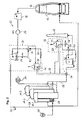
- Fig. 1 schematically shows a blast furnace plant 10 equipped with a top gas treatment installation.
- the blast furnace plant 10 comprises a blast furnace 12 and a plurality of at least three regenerative heaters 14.1, 14.2 and 14.3.
- the top gas treatment installation recovers top gas 16 from the top of the blast furnace 12.
- the collected top gas can then be used in the blast furnace plant and/or in other installations as an energy carrier.
- part of the recovered top gas and/or BOF gas may optionally be injected into the blast furnace, at an upper level thereof, as a reduction gas (not shown in the figures).
- the top gas and/or the BOF gas may be cold or preheated when re-injected.
- the top gas 16 is collected at the top of the blast furnace 12 and subjected to an initial cleaning to remove e.g. dust particles.
- the cleaning installation 18 is illustrated as a spray washer.
- the cleaning installation 18 also comprises a dry dust-catcher and, optionally, also an electrical precipitator (not shown).
- the cleaned top gas Downstream of the cleaning installation, the cleaned top gas is subjected to CO 2 removal in a first CO 2 removal installation 20.
- the CO 2 -depleted top gas is then depressurized using a top gas recovery turbine (TRT) 22 and passed to a top gas network, which the regenerative heaters 14.1, 14.2 and 14.3 are connected to in such a way as to receive the CO 2 -depleted top gas as a fuel gas.
- the regenerative heaters are alternately operated "on blast” and "on gas”.
- the cyclic operations of the regenerative heaters 14.1, 14.2, 14.3 are dephased amongst each other such that, with three regenerative heaters, at any time during the normal operation of the blast furnace plant 10, one of the regenerative heaters 14.1, 14.2, 14.3 is operated on blast while the two others are operated on gas.
- the transitions between heating and blowing and vice-versa are synchronized, in such a way that when the regenerative heater on blast changes over to on-gas operation, one of the regenerative heaters on gas takes over the blowing.
- the regenerative heater that is operated on blast receives air (cold blast) from a blower 24.
- the air is heated up in the regenerative heater and then injected into the blast furnace 12 as the hot blast.
- a part 26 of the CO 2 -depleted top gas is used to fuel the burners 28 of the regenerative heaters.
- a fan 29 supplies the burners 28 with air to burn the CO 2 -depleted top gas.
- Another option would be to mix flue gases from the regenerative heaters 14.1, 14.2, 14.3 with pure oxygen to form an oxidizing gas, which the burners 28 use to burn the CO 2 -depleted top gas.
- the CO 2 -depleted top gas could also be burnt in pure oxygen, provided that appropriate burners are used.
- Any CO 2 -depleted top gas 30 that is not re-injected into the blast furnace as reduction gas or burnt to heat up the regenerative heaters may be distributed to other installations via the top gas network.
- the top gas network In an integrated steel mill, among the installations that may use the top gas are, for instance, a coke oven plant, a power plant, a hot strip mill etc.
- the flue gases produced by the combustion of CO 2 -depleted top gas in the regenerative heaters 14.1, 14.2 and 14.3 are supplied to a second CO 2 removal installation 32. After removal of CO 2 , the residual flue gases are evacuated through the chimney 64.
- Each of the CO 2 removal installations 20, 32 implements a wet CO 2 removal process.
- Each of the CO 2 removal installations 20, 32 comprises an absorber 34, 36 and a stripper 38, 40.
- a washing liquid such as e.g. an aqueous amine solution
- the gas to be cleaned i.e. the top gas from the blast furnace or the flues gases from the regenerative heaters
- the washing liquid absorbs CO 2 from the gas stream.
- the washing liquids rich in the absorbed CO 2 42, 44 are then routed into the respective stripper 38, 40.
- the strippers 38, 40 the washing liquids are heated, whereby the solubility of CO 2 is reduced.
- the washing liquids are oversaturated in CO 2 , which is therefore released and may be recuperated.
- the lean washing liquids 46, 48 are recycled into the respective absorbers 34, 36.
- a heat exchanger 50, 52 is arranged in the washing liquid conduits between the absorber 34, 36 and the stripper 38, 40, in which heat is transferred from the lean washing liquid 46, 48 coming from the stripper 38, 40 to the rich washing liquid 42, 44 coming from the absorber 34, 36.
- Heat that is necessary for the functioning of the CO 2 removal installations 20, 32 is taken from the flue gases produced in the combustion of CO 2 -depleted top gas in the regenerative heaters 14.1, 14.2 and 14.3.
- a heat exchanger 54 arranged in the exhaust conduit 56 of the regenerative heaters 14.1, 14.2 and 14.3 transfers heat (excess heat that has not been taken up by the regenerative heaters) from the flue gases to a heat transfer medium (e.g. water, thermal oil or the like) circulating in a heating circuit 58.
- the heating circuit 58 is connected to heat exchangers 60 and 62 arranged in the strippers 38 and 40, respectively, which transfer heat from the heat transfer medium to the washing liquid.
- the removal of CO 2 from the top gas in the absorber 34 increases the concentration of CO in the residual gas flow (the CO 2 -depleted top gas). Accordingly, the heating value (kJ/m 3 ) is increased. As a consequence, if CO 2 -depleted top gas is burnt in the regenerative heaters 14.1, 14.2, 14.3, the temperature of the combustion products (flue gases) is higher. If the regenerative heaters have been optimized for a lower flame temperature (obtained with top gas having the original CO 2 concentration), they will be less efficient when fired with CO 2 -depleted top gas. The waste gases will carry excess heat away. Thanks to the invention, this excess heat is not lost but used to heat the washing liquids. As those skilled will appreciate, the invention is particularly suited for upgrading existing blast furnace plants, since existing regenerative heaters can continue to be used. In particular, the invention represents an efficient way for removal of CO 2 from the blast furnace process.
- Fig. 2 illustrates a variant of the blast furnace plant of Fig. 1 .
- the first CO 2 removal installation 20 is arranged on the high-pressure side of the top gas recovery turbine 22, in Fig. 2 , the first CO 2 removal installation 20 is arranged on the low-pressure side of the turbine 22.
- Fig. 2 is identical to Fig. 1 and need not be described further. Nevertheless, it is worthwhile noting that the variant of Fig. 1 (top gas cleaning upstream of TRT) is currently believed to be the more advantageous from the thermo-chemical point of view.
- the CO 2 absorption process including the washing liquid has to work under the pressure upstream of the TRT, which means that the first CO 2 removal installation 20 has to be designed for this high pressure.
- the solution of Fig. 2 has the advantage that the first CO 2 removal installation 20 operates at the lower pressure downstream of the TRT. More practical experience still has to be collected before all the advantages and disadvantages of both variants are finally known.
- the CO 2 removed from the top gas and the flue gases, respectively, is preferably transported to a CCS facility and stored in deep geological formations or in the form of mineral carbonates. While specific embodiments have been described in detail, those skilled in the art will appreciate that various modifications and alternatives to those details could be developed in light of the overall teachings of the disclosure. Accordingly, the particular arrangements disclosed are meant to be illustrative only and not limiting as to the scope of the invention, which is to be given the full breadth of the appended claims and any and all equivalents thereof.
Landscapes
- Engineering & Computer Science (AREA)
- Chemical & Material Sciences (AREA)
- Mechanical Engineering (AREA)
- General Engineering & Computer Science (AREA)
- Chemical Kinetics & Catalysis (AREA)
- Organic Chemistry (AREA)
- General Chemical & Material Sciences (AREA)
- Oil, Petroleum & Natural Gas (AREA)
- Environmental & Geological Engineering (AREA)
- Combustion & Propulsion (AREA)
- Manufacturing & Machinery (AREA)
- Materials Engineering (AREA)
- Metallurgy (AREA)
- Analytical Chemistry (AREA)
- Gas Separation By Absorption (AREA)
- Treating Waste Gases (AREA)
- Carbon And Carbon Compounds (AREA)
Priority Applications (1)
| Application Number | Priority Date | Filing Date | Title |
|---|---|---|---|
| EP11187308.9A EP2587204A1 (en) | 2011-10-31 | 2011-10-31 | Blast furnace top gas treatment |
Applications Claiming Priority (1)
| Application Number | Priority Date | Filing Date | Title |
|---|---|---|---|
| EP11187308.9A EP2587204A1 (en) | 2011-10-31 | 2011-10-31 | Blast furnace top gas treatment |
Publications (1)
| Publication Number | Publication Date |
|---|---|
| EP2587204A1 true EP2587204A1 (en) | 2013-05-01 |
Family
ID=44862825
Family Applications (1)
| Application Number | Title | Priority Date | Filing Date |
|---|---|---|---|
| EP11187308.9A Withdrawn EP2587204A1 (en) | 2011-10-31 | 2011-10-31 | Blast furnace top gas treatment |
Country Status (1)
| Country | Link |
|---|---|
| EP (1) | EP2587204A1 (da) |
Cited By (2)
| Publication number | Priority date | Publication date | Assignee | Title |
|---|---|---|---|---|
| AU2016269404B2 (en) * | 2015-12-14 | 2018-02-15 | Kabushiki Kaisha Toshiba | A carbon dioxide capture system and a method of operating a carbon dioxide capture system |
| CN113149012A (zh) * | 2021-03-29 | 2021-07-23 | 本钢板材股份有限公司 | 一种利用高炉煤气提取二氧化碳的方法 |
Citations (8)
| Publication number | Priority date | Publication date | Assignee | Title |
|---|---|---|---|---|
| DE3248249C1 (de) | 1982-12-28 | 1984-08-02 | Didier-Werke Ag, 6200 Wiesbaden | Verfahren zur Erhöhung der Heißwindtemperatur im Hochofenprozeß |
| US6045602A (en) * | 1998-10-28 | 2000-04-04 | Praxair Technology, Inc. | Method for integrating a blast furnace and a direct reduction reactor using cryogenic rectification |
| FR2848123A1 (fr) * | 2002-12-04 | 2004-06-11 | Air Liquide | Procede de recuperation du gaz de haut-fourneau et son utilisation pour la fabrication de la fonte |
| JP2005195283A (ja) * | 2004-01-08 | 2005-07-21 | Nippon Steel Corp | ステーブクーラの循環冷媒の廃熱を用いた副生ガス中のco2吸収法 |
| US20100212457A1 (en) * | 2009-02-24 | 2010-08-26 | Raymond Francis Drnevich | Producing metal and carbon dioxide with hydrogen recycle |
| WO2010124992A1 (en) * | 2009-04-28 | 2010-11-04 | Paul Wurth S.A. | Method for feeding a burden to a blast furnace |
| WO2011029814A1 (de) | 2009-09-11 | 2011-03-17 | Siemens Vai Metals Technologies Gmbh | Verfahren zur entfernung von co2 aus abgasen, wie abgase aus anlagen zur roheisenherstellung oder abgase aus synthesegasanlagen |
| CN102210963A (zh) * | 2011-06-15 | 2011-10-12 | 童师颖 | 乙醇胺富液余热解析系统 |
-
2011
- 2011-10-31 EP EP11187308.9A patent/EP2587204A1/en not_active Withdrawn
Patent Citations (8)
| Publication number | Priority date | Publication date | Assignee | Title |
|---|---|---|---|---|
| DE3248249C1 (de) | 1982-12-28 | 1984-08-02 | Didier-Werke Ag, 6200 Wiesbaden | Verfahren zur Erhöhung der Heißwindtemperatur im Hochofenprozeß |
| US6045602A (en) * | 1998-10-28 | 2000-04-04 | Praxair Technology, Inc. | Method for integrating a blast furnace and a direct reduction reactor using cryogenic rectification |
| FR2848123A1 (fr) * | 2002-12-04 | 2004-06-11 | Air Liquide | Procede de recuperation du gaz de haut-fourneau et son utilisation pour la fabrication de la fonte |
| JP2005195283A (ja) * | 2004-01-08 | 2005-07-21 | Nippon Steel Corp | ステーブクーラの循環冷媒の廃熱を用いた副生ガス中のco2吸収法 |
| US20100212457A1 (en) * | 2009-02-24 | 2010-08-26 | Raymond Francis Drnevich | Producing metal and carbon dioxide with hydrogen recycle |
| WO2010124992A1 (en) * | 2009-04-28 | 2010-11-04 | Paul Wurth S.A. | Method for feeding a burden to a blast furnace |
| WO2011029814A1 (de) | 2009-09-11 | 2011-03-17 | Siemens Vai Metals Technologies Gmbh | Verfahren zur entfernung von co2 aus abgasen, wie abgase aus anlagen zur roheisenherstellung oder abgase aus synthesegasanlagen |
| CN102210963A (zh) * | 2011-06-15 | 2011-10-12 | 童师颖 | 乙醇胺富液余热解析系统 |
Cited By (2)
| Publication number | Priority date | Publication date | Assignee | Title |
|---|---|---|---|---|
| AU2016269404B2 (en) * | 2015-12-14 | 2018-02-15 | Kabushiki Kaisha Toshiba | A carbon dioxide capture system and a method of operating a carbon dioxide capture system |
| CN113149012A (zh) * | 2021-03-29 | 2021-07-23 | 本钢板材股份有限公司 | 一种利用高炉煤气提取二氧化碳的方法 |
Similar Documents
| Publication | Publication Date | Title |
|---|---|---|
| JP4745682B2 (ja) | Co2回収装置および方法 | |
| CN106996702B (zh) | 一种铁矿烧结烟气分段富集及余热利用减排SOx和NOx方法 | |
| WO2005097299A1 (ja) | Co2回収装置及び方法 | |
| JP2009221575A (ja) | 高炉ガスの利用プロセスにおける高炉ガスからの二酸化炭素の分離回収方法 | |
| JP5184061B2 (ja) | 高炉ガスからの二酸化炭素の分離回収方法 | |
| JPWO2011108086A1 (ja) | 二酸化炭素除去装置を備えた排ガス処理システム | |
| US10569215B2 (en) | Systems and methods for reducing the energy requirements of a carbon dioxide capture plant | |
| JP5944042B2 (ja) | 排ガス処理システム及び排ガス処理方法 | |
| CN110354670A (zh) | 一种炭黑尾气锅炉烟气脱白系统和方法 | |
| CN208372813U (zh) | 用于垃圾焚烧联合发电厂的烟气处理系统 | |
| JP5242206B2 (ja) | 高炉ガスからの二酸化炭素分離回収方法 | |
| EP2587204A1 (en) | Blast furnace top gas treatment | |
| JP2012115779A (ja) | Co2回収システム | |
| KR101299894B1 (ko) | 고로 가스의 이용 프로세스에 있어서의 고로 가스로부터의 이산화탄소의 분리 회수 방법 | |
| EP2634483A2 (en) | Method for providing heat to post combustion capture process | |
| US9987587B2 (en) | Method and device for the treatment of a gas stream, in particular for the treatment of a natural gas stream | |
| EP2943267B1 (en) | Systems and methods for reducing the energy requirements of a carbon dioxide capture plant | |
| CN208372792U (zh) | 垃圾焚烧发电厂的烟气处理系统 | |
| KR20110129365A (ko) | 환경오염 방지시설의 배출가스 탈질장치 승온시스템 및 이를 적용한 배출가스 처리시스템 | |
| CN206942820U (zh) | 一种利用燃气和蒸汽联合发电的设备 | |
| JP6278576B2 (ja) | 低質炭を用いた発電システム | |
| WO2016186512A1 (en) | A system and method for recovering waste heat from a combined industrial and thermal power plant. | |
| KR101292488B1 (ko) | 고로 가스로부터의 이산화탄소 분리 회수 방법 | |
| US20140250887A1 (en) | Power generation system making use of low grade coal | |
| JP2007247048A (ja) | 高炉炉頂発電方法および装置 |
Legal Events
| Date | Code | Title | Description |
|---|---|---|---|
| PUAI | Public reference made under article 153(3) epc to a published international application that has entered the european phase |
Free format text: ORIGINAL CODE: 0009012 |
|
| AK | Designated contracting states |
Kind code of ref document: A1 Designated state(s): AL AT BE BG CH CY CZ DE DK EE ES FI FR GB GR HR HU IE IS IT LI LT LU LV MC MK MT NL NO PL PT RO RS SE SI SK SM TR |
|
| AX | Request for extension of the european patent |
Extension state: BA ME |
|
| STAA | Information on the status of an ep patent application or granted ep patent |
Free format text: STATUS: THE APPLICATION IS DEEMED TO BE WITHDRAWN |
|
| 18D | Application deemed to be withdrawn |
Effective date: 20131105 |