EP2586918A2 - Appareil et procédé pour commander une trajectoire de travail d'une machine de construction - Google Patents
Appareil et procédé pour commander une trajectoire de travail d'une machine de construction Download PDFInfo
- Publication number
- EP2586918A2 EP2586918A2 EP11798396.5A EP11798396A EP2586918A2 EP 2586918 A2 EP2586918 A2 EP 2586918A2 EP 11798396 A EP11798396 A EP 11798396A EP 2586918 A2 EP2586918 A2 EP 2586918A2
- Authority
- EP
- European Patent Office
- Prior art keywords
- work device
- driving
- work
- trajectory
- posture
- Prior art date
- Legal status (The legal status is an assumption and is not a legal conclusion. Google has not performed a legal analysis and makes no representation as to the accuracy of the status listed.)
- Withdrawn
Links
Images


Classifications
-
- E—FIXED CONSTRUCTIONS
- E02—HYDRAULIC ENGINEERING; FOUNDATIONS; SOIL SHIFTING
- E02F—DREDGING; SOIL-SHIFTING
- E02F9/00—Component parts of dredgers or soil-shifting machines, not restricted to one of the kinds covered by groups E02F3/00 - E02F7/00
- E02F9/20—Drives; Control devices
- E02F9/2025—Particular purposes of control systems not otherwise provided for
-
- E—FIXED CONSTRUCTIONS
- E02—HYDRAULIC ENGINEERING; FOUNDATIONS; SOIL SHIFTING
- E02F—DREDGING; SOIL-SHIFTING
- E02F3/00—Dredgers; Soil-shifting machines
- E02F3/04—Dredgers; Soil-shifting machines mechanically-driven
- E02F3/28—Dredgers; Soil-shifting machines mechanically-driven with digging tools mounted on a dipper- or bucket-arm, i.e. there is either one arm or a pair of arms, e.g. dippers, buckets
- E02F3/36—Component parts
- E02F3/42—Drives for dippers, buckets, dipper-arms or bucket-arms
- E02F3/43—Control of dipper or bucket position; Control of sequence of drive operations
- E02F3/431—Control of dipper or bucket position; Control of sequence of drive operations for bucket-arms, front-end loaders, dumpers or the like
- E02F3/434—Control of dipper or bucket position; Control of sequence of drive operations for bucket-arms, front-end loaders, dumpers or the like providing automatic sequences of movements, e.g. automatic dumping or loading, automatic return-to-dig
-
- E—FIXED CONSTRUCTIONS
- E02—HYDRAULIC ENGINEERING; FOUNDATIONS; SOIL SHIFTING
- E02F—DREDGING; SOIL-SHIFTING
- E02F3/00—Dredgers; Soil-shifting machines
- E02F3/04—Dredgers; Soil-shifting machines mechanically-driven
- E02F3/28—Dredgers; Soil-shifting machines mechanically-driven with digging tools mounted on a dipper- or bucket-arm, i.e. there is either one arm or a pair of arms, e.g. dippers, buckets
- E02F3/36—Component parts
- E02F3/42—Drives for dippers, buckets, dipper-arms or bucket-arms
- E02F3/43—Control of dipper or bucket position; Control of sequence of drive operations
- E02F3/435—Control of dipper or bucket position; Control of sequence of drive operations for dipper-arms, backhoes or the like
- E02F3/437—Control of dipper or bucket position; Control of sequence of drive operations for dipper-arms, backhoes or the like providing automatic sequences of movements, e.g. linear excavation, keeping dipper angle constant
-
- E—FIXED CONSTRUCTIONS
- E02—HYDRAULIC ENGINEERING; FOUNDATIONS; SOIL SHIFTING
- E02F—DREDGING; SOIL-SHIFTING
- E02F3/00—Dredgers; Soil-shifting machines
- E02F3/04—Dredgers; Soil-shifting machines mechanically-driven
- E02F3/28—Dredgers; Soil-shifting machines mechanically-driven with digging tools mounted on a dipper- or bucket-arm, i.e. there is either one arm or a pair of arms, e.g. dippers, buckets
- E02F3/36—Component parts
- E02F3/42—Drives for dippers, buckets, dipper-arms or bucket-arms
- E02F3/43—Control of dipper or bucket position; Control of sequence of drive operations
- E02F3/435—Control of dipper or bucket position; Control of sequence of drive operations for dipper-arms, backhoes or the like
- E02F3/438—Memorising movements for repetition, e.g. play-back capability
-
- E—FIXED CONSTRUCTIONS
- E02—HYDRAULIC ENGINEERING; FOUNDATIONS; SOIL SHIFTING
- E02F—DREDGING; SOIL-SHIFTING
- E02F9/00—Component parts of dredgers or soil-shifting machines, not restricted to one of the kinds covered by groups E02F3/00 - E02F7/00
- E02F9/20—Drives; Control devices
- E02F9/2025—Particular purposes of control systems not otherwise provided for
- E02F9/2029—Controlling the position of implements in function of its load, e.g. modifying the attitude of implements in accordance to vehicle speed
-
- E—FIXED CONSTRUCTIONS
- E02—HYDRAULIC ENGINEERING; FOUNDATIONS; SOIL SHIFTING
- E02F—DREDGING; SOIL-SHIFTING
- E02F9/00—Component parts of dredgers or soil-shifting machines, not restricted to one of the kinds covered by groups E02F3/00 - E02F7/00
- E02F9/26—Indicating devices
- E02F9/264—Sensors and their calibration for indicating the position of the work tool
- E02F9/265—Sensors and their calibration for indicating the position of the work tool with follow-up actions (e.g. control signals sent to actuate the work tool)
Definitions
- the present invention relates to a apparatus and method for controlling work trajectory of construction equipment, and particularly, to a trajectory controlling device and method for construction equipment, capable of automatically operating in the most suitable work trajectory at the point when an automated task is selected.
- an excavator is configured with: respective work devices (for example, a boom, an arm, and a bucket); a boom cylinder, an arm cylinder, and a bucket cylinder for driving the work devices, respectively; a swing motor for the swing operation of an excavator body; and a motor and a hydraulic pump for supplying compressed oil as a power source to the respective cylinders.
- work devices for example, a boom, an arm, and a bucket
- a boom cylinder, an arm cylinder, and a bucket cylinder for driving the work devices, respectively
- a swing motor for the swing operation of an excavator body
- a motor and a hydraulic pump for supplying compressed oil as a power source to the respective cylinders.
- An excavator is hydraulic construction equipment that performs excavating, ridging, stationary work, and many other types of work.
- an intelligent excavator may help to reduce labor costs and reduce the risk of accidents.
- an intelligent excavator may help to reduce labor costs and reduce the risk of accidents.
- the present invetion is made to solve the problems, and an object of the present invention is to provide a trajectory controlling device and method for construction equipment, capable of automatically operating with the most suitable work trajectory at the point when an automated task is selected.
- the obejct of the present invention is to provide a trajectory controlling device and method for construction equipment, which employ a database and are capable of performing an automated task in a work trajectory at a point after the posture of a bucket that is not in a work trajectory of a selected point has been corrected, in consideration of the current posture of the bucket, when automated excavation is selected.
- Another object of the present invention is to provide a apparatus and method for controlling work trajectory of construction equipment, which use teaching and playback to minimize positioning errors when an automated task is performed to follow a teaching trajectory designated by an operator.
- a work trajectory controlling device for construction equipment having at least one work device, and a driving unit for driving the work device
- the work trajectory controlling device including: an actuating unit configured to generate a joystick signal through a manipulation by an operator; a data storage unit configured to store driving trajectory data on the work device, for the work device, to be driven upon starting of an automated task, to follow; and a driving controller configured, upon the starting of the automated task, to read trajectory data on the work device stored in the data storage unit, and control the driving unit to drive the work device to follow the read driving trajectory data, wherein when the automated task is selected, and an actual position of the work device falls within a reference error range between a position at which driving of the work device is started which is stored in the data storage unit, and a preset position at which driving of the work device is started, the driving controller performs controlling to start automated driving in a position at a time when the automated task is selected and controls the driving unit to follow the prestored driving trajectory over time while the automated driving
- a work trajectory controlling method for construction equipment having at least one work device, a driving unit configured to drive the work device, and an actuating unit configured to generate a joystick signal through a manipulation by an operator, the method including: checking whether an automated task is selected; and when the automated task is selected, comparing an actual position of the work device with a preset automated task starting position, and comparing a difference thereof with a preset reference error, wherein when results of the comparison show that a difference between the actual position of the work device and the preset automated task starting position is less than the reference error, preset trajectory data on the work device is read, and trajectory data is generated for an automated task starting at the actual position of the work device, after which the automated task is started, and the new trajectory data is generated to follow the preset trajectory data of the work device as time elapses.
- automated work is possible based on the current posture of a work device when an automated task is selected, and it is possible to prevent the automated task from being performed inefficiently due to an improper posture of the work device when the automated task is begun.
- work may be easily performed even by an inexperienced operator, through an automated task selection function.
- a positioning error is compensated for to enable a work device to be driven in a trajectory desired by an operator.
- the operator may perform work within desired work parameters in a short time when the difference is not great.
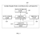
- FIG. 1 is a configurative diagram of a work trajectory controlling device for construction equipment according to an exemplary embodiment of the present invention.
- a work trajectory controlling device 100 includes an actuating unit 110, a driving controller 120, a gravity compensating unit 130, a driving unit 140, and a data storage unit 150.
- the work trajectory controlling device 100 controls the work trajectory of construction equipment, and includes at least one work device, and the driving unit 140 for driving the work device.
- the position of a work device is described in terms of having a large positioning error or a small positioning error with respect to a preset reference value, and a case in which a work trajectory controlling device for construction equipment operates using a database and a case in which a work trajectory controlling device for construction equipment operates using teaching and playback are described. Also, an example of applying the present invention to an excavator among the work devices will be described.
- Preset driving trajectory data for a work device is stored in the data storage unit 150, in order for an automated task to be started at a position corresponding to any of the positions of the work device. That is, the data storage unit 150 builds and stores a database with driving trajectory data for each set of position coordinates for the end of the excavator bucket.
- the driving trajectory data includes joystick data and cylinder length data, or angle data on each link of the boom, the arm, and the bucket.
- the above-described driving trajectory data is described in terms of the position of the bucket, as an example. However, the present invention is not necessarily limited thereto, and trajectory data may be formed on the basis of the boom, the arm, and various other work devices.
- the bucket forms the basis for the trajectory data as in the present exemplary embodiment
- the moving trajectory of the bucket that directly contacts the surface that is actually worked is very similar to the work parameters intended by the operator, it may be preferable to perform controlling with the position of the bucket at the center, as in the present exemplary embodiment.
- the data storage unit 150 stores driving trajectory data for each set of position coordinates that may begin at position coordinates of the end of the excavator bucket as a reference, and may include driving trajectory data from all points on which the end of the bucket may be disposed. Also, the driving trajectory data is made and stored as a database, in terms of the desirable bucket angles for performing tasks. At the time the excavator is delivered, driving trajectory data related to excavating at all points may be compiled in a database. Such driving trajectory data based on position may be set through the following example. First, the range over which the end of the bucket is driven for a task is divided into ranges of predetermined sizes. Excavating, flattening, trenching, and other tasks are predicted to respectively be performed from where the end of the bucket is disposed at the center of each range, and trajectory data based thereon is prestored.
- the actuating unit 110 Based on manipulations by an operator, the actuating unit 110 outputs information on whether automated task start has been selected and position information on the work device at the time when the automated task is started to the driving controller 120.
- the actuating unit 110 may include a joystick or an automated task start button, or the like.
- a joystick signal, an automated task button signal, or the like is output according to the manipulations of the operator.
- the driving controller 120 reads driving trajectory data corresponding to the current position of the work device from the data storage unit 150, and controls the driving unit 140 to drive the work device to follow the driving trajectory data read from the data storage unit 150.
- the driving controller 120 checks the posture of the work device.
- the driving controller 120 controls the driving unit 140 so that the work device is changed in posture so as to be capable of performing the designated task.
- the driving controller 120 checks whether the new position of the work device brought about by the change in posture will be largely different from a preset reference value.
- the driving controller 120 reads new driving trajectory data corresponding to a new position changed by a change in the posture of the bucket from the data storage unit 150, and then controls the driving unit 140 so that the work device is driven to follow the new driving trajectory data. Conversely, when the checked results for the reference value show that the new position will not differ largely from the preset reference value, the driving controller 120 controls the driving unit 140 so that the work device is driven to follow driving trajectory data corresponding to the initially selected position.
- the driving controller 120 checks the posture of the bucket when an automated task is started. When the checked results show that the posture of the bucket is similar to a reference posture, the driving unit 140 is controlled so that driving trajectory data will be followed at the time of an operator's selection. Conversely, when the posture of the bucket differs largely from the reference posture, the driving controller 120 changes the posture of the bucket. The driving controller 120 changes the angle of bucket to a reference bucket angle at the time of the operator's selection, in consideration of the current bucket angle.
- the driving controller 120 checks for a position change brought about by a change in the posture of the bucket.
- the excavator includes the bucket, and the driving controller 120 determines whether there is a change in the posture of the excavator based on the posture of the bucket.
- the driving controller 120 controls the driving unit 140 so that the initially selected trajectory data is ultimately followed.
- the driving controller 120 reads new driving trajectory data corresponding to the changed position from the data storage unit 150, and then controls the driving unit 140 so that the new driving trajectory data is followed.
- whether or not the new driving trajectory data is to be read is selected based on a position change of the bucket corresponding to a change in the posture of the bucket.
- the driving controller 120 has various sensors so that when it is sensed that a change in the posture of the bucket will be impeded by an obstacle such as a ground surface, the posture of the bucket may be changed by automatically driving other work devices such as the boom/arm in an optimized trajectory.
- the driving controller 120 compares a preset bucket angle (for example, 10°) to the current bucket angle, and controls the driving unit 140 to move the bucket cylinder when the current bucket angle exceeds the preset angle, so that the bucket angle falls within the preset angle. If it is determined that the bucket is stuck on the ground surface or in a difficult-to-drive situation, the driving controller 120 controls the driving unit 140 to actuate the cylinders of the boom, arm, and bucket together in order to set the bucket angle in order to set the bucket angle.
- a preset bucket angle for example, 10°
- the driving controller 120 reads new driving trajectory data for the changed position from the data storage unit 150.
- the driving controller 120 may control a task starting point and the following of a trajectory so as to compensate for a positioning error based on driving trajectory data stored in the data storage unit 150, and may compensate for changes related to gravity brought about by posture changes, in order to minimize positioning errors for the end of the bucket of the excavator and control the driving of the excavator.
- the driving controller 120 may apply a gravity compensating value, calculated by the gravity compensating unit 130, for drive control. Length data for each cylinder of the excavator may be substituted with angle data on each link of the boom, arm, and bucket.
- the driving controller 120 controls the driving unit 140 to stop the automated task and follow the new joystick signal that is generated.
- the driving controller 120 obtainsdriving trajectory data (for example, joystick data (Joy_ref data) and cylinder length data (Cyl_ref data)) that is stored in the data storage unit 150. Also, the driving controller 120 adds a joystick signal (O_Joy), a positioning error signal (O_PI1), and a gravity compensating signal value (Ga), and outputs a drive control signal (Com_out) to the driving unit 140.
- trajectory data for example, joystick data (Joy_ref data) and cylinder length data (Cyl_ref data)
- the driving controller 120 adds a joystick signal (O_Joy), a positioning error signal (O_PI1), and a gravity compensating signal value (Ga), and outputs a drive control signal (Com_out) to the driving unit 140.
- the driving controller 120 obtains a joystick signal (O_Joy) from joystick data (Joy_ref data). Also, the driving controller 120 subtracts a cylinder length signal and a current measured signal from the cylinder length data (Cyl_ref data) to obtain an error signal (Er). In addition, the driving controller 120 uses the error signal (Er) to calculate a positioning error signal (O_PI1) through a PI controller.
- the gravity compensating unit 130 obtains a mass inertia moment through a current posture change of the excavator and calculates a gravity compensating value (Ga). This is to minimize a positioning error for the end of the bucket caused by a posture change of the excavator.
- the driving controller 120 calculates a driving output value (O_joy+O_PI1+Ga) which is the sum of the joystick signal (O_Joy), the positioning error signal (O_PI1), and the gravity compensating value (Ga). Also, the driving controller 120 converts the added driving output value (O_joy+O_PI1+Ga) to a drive control signal (Com_out) to output to the driving unit 140.
- a driving output value O_joy+O_PI1+Ga
- Com_out drive control signal
- the driving controller 120 assumes an emergency situation and controls the driving unit 140 to stop the automated task and follow the joystick signal generated by the actuating unit 110.
- FIG. 2 is a diagram illustrating an example of using a database to control the work trajectory of construction equipment according to an exemplary embodiment of the present invention.
- the data storage unit 150 forms a database with driving trajectory data at coordinates (211) at which the end of the bucket is disposed, and stores the database.
- the data storage unit 150 designates a bucket position at which excavation is possible as a position coordinate value, and stores driving trajectory data corresponding to the designated position coordinate value as a database.
- all position coordinates 210 are represented by (0, 0) to (x, y) in the database.
- x and y are position coordinates representing positions at which excavation is possible in a basic length unit.
- x and y represent the maximum position coordinates, at which an excavating task is possible within the range in which the excavator operates.
- the data storage unit 150 stores driving trajectory data on the position coordinates 211 at a selected point.
- the driving controller 120 requests driving trajectory data on the position coordinates 211
- the data storage unit 150 relays driving trajectory data on the position coordinates 211 to the driving controller 120.
- the driving trajectory data may include joystick data and cylinder length data, or angle data on each link of the boom, arm, and bucket, relayed from the driving controller 120.
- the present invention relates to a apparatus and method for controlling work trajectory of construction equipment which are capable of minimizing positioning errors when playback is selected, whereby an operator rides a work device (for example, an excavator and a wheel loader) and a trajectory for performing a certain task is stored in the work device (this task is hereinafter referred to as "teaching"), and the stored trajectory (for example, for the position of the end of a bucket) is followed to drive the work device automatically.
- a work device for example, an excavator and a wheel loader
- this task is hereinafter referred to as "teaching"
- the stored trajectory for example, for the position of the end of a bucket
- the work trajectory controlling device 100 is operated in teaching mode or in playback mode.
- the actuating unit 110 generates a joystick signal through manipulation by an operator, and the operator may select and actuate teaching mode and playback mode.
- teaching mode denotes a mode in which an operator teaches a task process of an excavator.
- the work trajectory controlling device 100 stores the joystick signal according to the joystick manipulation and each piece of cylinder length data (hereinafter referred to as "driving data") of the driving unit 140.
- driving data each piece of cylinder length data
- the operator may start or end teaching mode through a teaching start and end button, and the like provided on the actuating unit 110 of the excavator.
- the actuating unit 110 transfers joystick signals generated according to the manipulation of the joystick by the operator to the driving controller 120.
- the driving controller 120 receives the joystick signals from the actuating unit 110 and controls the driving of the driving unit 140.
- the driving controller 120 processes driving data on the work device and the joystick signals corresponding to the manipulations of the operator, and stores generated trajectory data in the data storage unit 150. That is, the driving controller 120 stores the joystick signals transferred from the actuating unit 110 as joystick data in the data storage unit 150.
- the driving controller 120 stores cylinder length data of the boom, arm, and bucket driven by the driving unit 140, or angle data for each link in the boom, arm, and bucket in the data storage unit 150.
- the driving unit 140 drives the cylinders of the boom, arm, and bucket according to the drive control of the driving controller 120.
- the playback mode denotes a mode in which the work trajectory controlling device 100 automatically plays back the task process stored in the teaching mode.
- the data storage unit 150 stores trajectory data (for example, joystick data and data on the length of each cylinder) taught in teaching mode. Also, the data storage unit 150 may store joystick data and angle data for each link of the boom, arm, and bucket as trajectory data.
- trajectory data for example, joystick data and data on the length of each cylinder
- the driving controller 120 controls the driving unit 140 to automatically drive the work device to follow trajectory data stored in the data storage unit 150 in teaching mode.
- the position of the work device is compared to a starting position of the work device stored in the data storage unit 150 at the point when playback mode is selected.
- the driving controller 120 performs controlling to start automated driving at the position at which playback mode is selected. Any of the work devices may be used to measure the positioning error range.
- the present exemplary embodiment describes an example of a controlling method that sets the position of the bucket, which directly contacts the surface to be worked and can be said to be central to the task, as the basis for performing controlling.
- the driving controller 120 controls the driving unit 140 to follow a preset driving trajectory as the time elapses in which automated driving is performed. This is to enable a task to be performed within an initially input working range as time elapses, even when automated driving is started at a point not desired by an operator.
- the driving controller 120 compensates for a positioning error with respect to the trajectory data stored in the data storage unit 150, while automated driving of the work device is performed.
- the driving of the excavator is controlled by compensating for the effects of gravity corresponding to the posture of the work device.
- the driving controller 120 applies a gravity compensating value calculated by the gravity compensating unit 130 and updates trajectory data, and controls the driving unit 140 on the basis of the updated trajectory data.
- Data on the length of each cylinder of the excavator from trajectory data may be substituted with angle data on each link of the boom, arm, and bucket.
- the gravity compensating unit 130 obtains a mass inertia moment through a change in the current posture of the excavator and calculates a gravity compensating value.
- the system may be configured to enable the operator to perform controlling through playback start and end buttons, and the like provided on the actuating unit 110 for starting/ending the playback mode.
- the controlling method above is described as an example in which the operator needs to move the work device back to the initial position for the desired task when desiring to reuse playback mode after playback mode is ended.
- the above-described playback mode is not necessarily limited thereto. That is, an application may be possible in which playback mode is selected to automatically repeat.
- playback mode is thus automatically repeated, as described above, controlling is possible where a portion where a task could not be performed when playback mode is initially started may be automatically redone. This may be accomplished by performing playback mode again after the work device is automatically moved to the initial position for the task which is automatically stored in teaching mode, when being repeated a second time. Accordingly, even when playback is started with the work device in an inaccurate position through the inexperienced performing of a task, the area intended to be worked by the operator may be worked by repeating the task.
- the method may be used of automatically controlling each work device so that the work device (more particularly, the bucket) is positioned at the playback mode starting point stored in teaching mode.
- the driving controller 120 may stop playback mode and control the driving unit 140 according to the new joystick signal generated from the actuating unit 110, in anticipation of a similarity.
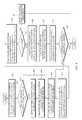
- FIG. 3 is a detailed configurative diagram of a work trajectory controlling device in playback mode according to an exemplary embodiment of the present invention.
- the driving controller 120 When the playback button is selected, the driving controller 120 performs controlling to estimate the task starting point and trajectory in order to compensate for the positioning error of the bucket, and minimizes the error to compensate for the effects of gravity brought about by a change in the posture of the work device.
- the driving controller 120 includes the processes of measuring the distance between the current position of the end of the bucket and the position of the end of the bucket when teaching mode is started, and of comparing a value of the difference between the current position of the end of the bucket and a preset initial position of the end of the bucket with a preset reference error (for example, 10 cm).
- a preset reference error for example, 10 cm.
- the work device when the difference value with the initial position is less than the reference error, and playback is started, the work device is operated directly at the position selected through the manipulation of the operator and is controlled to keep close to the taught driving trajectory as time passes. In this case, a portion of the work area intended by the operator at the start of playback may not have been worked, and in this case when playback is repeatedly performed, the work device is automatically positioned at the taught initial position for the next session of playback work, to thereby solve the problem of the unworked area.
- a method may be used for indicating that playback work is not possible and waiting for a further manipulation by the operator, or for automatically positioning the work device to the playback initial position and then performing work by following a taught trajectory.
- the present exemplary embodiment is described as an example of moving the work device and then performing playback work.
- the driving controller 120 receives pre-taught joystick data (Joy_ref data) and cylinder length data (Cyl_ref data). Also, the driving controller 120 adds a joystick signal (O_Joy), a positioning error signal (O_PI1), and a gravity compensating value (Ga), and outputs a drive controlling signal (Com_out) to the driving unit 140.
- a joystick signal O_Joy
- O_PI1 positioning error signal
- Ga gravity compensating value
- the driving controller 120 receives the joystick signal (O_Joy) from the joystick data (Joy_ref data). Also, the driving controller 120 deducts a cylinder length signal and a currenly measured signal from the cylinder length data (Cyl_ref data) to obtain an error signal (Er). The driving controller 120 also calculates a positioning error signal (O_PI1) from the error signal (Er) through a PI controller.
- the gravity compensating unit 130 calculates the gravity compensating value (Ga) by obtaining a mass inertia moment from the current posture of the work device.
- the driving controller 120 calculates a driving output value (O_joy+O_PI1+Ga) which is the sum of the joystick signal (O_Joy), the positioning error signal (O_PI1), and the gravity compensating value (Ga). Also, the driving controller 120 converts the summed driving output value (O_joy+O_PI1+Ga) to a drive controlling signal (Com_out) to output to the driving unit 140.
- a driving output value O_joy+O_PI1+Ga
- Com_out drive controlling signal
- the driving controller 120 When a joystick signal is generated by the actuating unit 110 for a preset time (for example, 0.3 sec) or more during playback, the driving controller 120 assumes an emergency situation and controls the driving of the driving unit 140 according to the joystick signal generated by the actuating unit 110.
- the method for controlling the work trajectory of construction equipment according to the present invention will be described as divided into a work trajectory controlling method for construction equipment using a database, and a work trajectory controlling method in teaching mode. First, a work trajectory controlling method for construction equipment using a database will be described.
- FIG. 4 is a flowchart of a method for controlling the work trajectory of construction equipment by using a database according to an exemplary embodiment of the present invention.
- an operator positions the work device at a desired position through a joystick and the like provided on the actuating unit 110. Then, when the operator selects an automated task start through an automated task selecting button and the like provided on the actuating unit 110, the automated task for the work device is selected.
- the work trajectory controlling device 100 calculates the current position of the bucket and receives driving trajectory data at those position coordinates from the database (DB) in step 402.
- the work trajectory controlling device 100 also compares the current posture of the bucket with a preset reference posture, and checks whether a difference between a current bucket angle at the current bucket position and a bucket angle in the database exceeds a certain angle (for example, 10°) in step 404.
- a certain angle for example, 10°
- the work trajectory controlling device 100 changes the posture of the work device to the reference posture.
- the work trajectory controlling device 100 moves the current bucket angle to the initial bucket angle in step 406.
- the initial bucket angle may be preset as a bucket angle that is preferable to perform an excavating task or may be set by the operator. If the bucket is stuck on the ground surface or is in a difficult-to-drive state, the work trajectory controlling device 100 may actuate the cylinders of the boom, arm, and bucket to move the bucket, in order to set the bucket angle.
- This state in which the bucket cannot be moved can be determined by sensing changes in the hydraulic pressure and changes in posture of each work device, and in the present exemplary embodiment, various sensors are installed on each hydraulic line and joint portions for that purpose.
- the work trajectory controlling device 100 receives trajectory data corresponding to a change in position of the work device according to a change in posture from the database, and controls the driving of the work device so that the work device is automatically driven to follow the read trajectory data.
- the work trajectory controlling device 100 calculates the changed position of the bucket and receives driving trajectory data on the position coordinates at which the end of the bucket is positioned from the database in step 408.
- step 404 when the checked results in step 404 show that the difference between the current bucket angle and the initial bucket angle is below a certain angle, the work trajectory controlling device 100 performs step 410 onward.
- the work trajectory controlling device 100 starts automated excavation in step 410 by using the driving trajectory data on the current position according to the received database in steps 402 or 408.
- the work trajectory controlling device 100 outputs joystick signals, which are stored at 10ms intervals, every 10ms in step 412.
- the work trajectory controlling device 100 checks whether the error between the cylinder length for even one of three cylinders, from the cylinder lengths stored for each cylinder, and the currently measured cylinder length is a preset cylinder length error value (for example, 5cm) or greater in step 416.
- step 416 When the checked results in step 416 show that the error between the reference cylinder length and the currently measured cylinder length is greater than the preset cylinder length error value (for example, 5cm), the work trajectory controlling device 100 shows the operator a message that the task cannot be performed and ends trajectory control in step 418.
- the preset cylinder length error value for example, 5cm
- a compensating value Ga
- O_PI O_PI1+Ga
- the work trajectory controlling device 100 compensates for when the effects of gravity on the boom, arm, and bucket are different, so as to perform fast and accurate control.
- the work trajectory controlling device 100 adds a gravity compensating value (Ga) corresponding to a gravity compensation to the positioning error signal (O_PI1) calculated in step 420 so that a greater output can be generated.
- the work trajectory controlling device 100 checks in step 426 whether an executing length matches a buffer length stored in the data storage unit 150.
- the work trajectory controlling device 100 When the results of the checking in step 426 show that the executing length does not match the buffer length, the work trajectory controlling device 100 outputs the driving output value calculated in step 424 and performs the steps again from step 412. Conversely, when the executing length and the buffer length match, the work trajectory controlling device 100 ends trajectory control together with a task completed message.
- the work trajectory controlling device 100 may assume an emergency situation, and end the automated task and control the work device according to the new joystick signal.
- a work trajectory controlling method in teaching mode will be described from among work trajectory controlling methods for construction equipment using teaching and playback according to the present invention.
- FIG. 5 is a flowchart of a method for controlling a work trajectory in teaching mode according to an exemplary embodiment of the present invention.
- the work trajectory controlling method according to the present invention is applied to a work trajectory controlling device 100 for construction equipment that includes at least one work device, a driving unit 140 for driving the work device, and an actuating unit 110 for generating a joystick signal corresponding to a manipulation by an operator, and is capable of selective operation in teaching mode and playback mode.
- the work trajectory controlling device 100 checks in step 502 whether a start button signal for indicating teaching start has been input by an operator.
- the work trajectory controlling device 100 stores the joystick signal generated by the manipulation of the operator and the driving data of the work device as trajectory data. That is, when the checked results in step 502 show that the start button is input, after the start button signal, the work trajectory controlling device 100 stores an angle at which the joystick is moved by the operator in preset time intervals (for example, 10ms), and senses and stores the cylinder length for each of the boom, arm, and bucket in step 504. For example, the work trajectory controlling device 100 may store the joystick angle and cylinder length at 10ms intervals. The work trajectory controlling device 100 may also sense and store the angles of each link of the boom, arm, and bucket.
- preset time intervals for example, 10ms
- the work trajectory controlling device 100 may calculate the cylinder length or angles of each link of the boom, arm, and bucket in order to mechanically calculate the position of the end of the bucket. Conversely, when the checked results in step 502 show that the start button signal is not input, the work trajectory controlling device 100 continuously monitors whether the start button signal is input.
- the work trajectory controlling device 100 checks in step 506 whether an end button signal indicating the end of teaching is input.
- step 506 When the checked results in step 506 show that the end button signal is input, the work trajectory controlling device 100 stores the joystick angles and cylinder lengths of the boom, arm, and bucket stored until the present as one piece of trajectory data. Conversely, when the end button signal is not input, the work trajectory controlling device 100 performs the steps again from 504, in which trajectory data is stored.
- FIG. 6 is a flowchart of a method for controlling a work trajectory in playback mode according to an exemplary embodiment of the present invention.
- the work trajectory controlling device 100 checks in step 602 whether a playback start button signal, indicating that playback is started by an operator, is input.
- step 602 When the checked results in step 602 show that the playback start button signal is input by the operator, the work trajectory controlling device 100 measures the distance between the current position of the end of the bucket and the position of the end of the bucket when teaching is started, and checks whether a difference value between the current position of the end of the bucket and a preset initial position of the end of the bucket exceeds a preset reference error (for example, 10cm) in step 604. Conversely, when the playback start button signal is not input by the operator, the work trajectory controlling device 100 performs step 602 onward until the playback start button signal is input.
- a preset reference error for example, 10cm
- the work trajectory controlling device 100 controls the bucket to move the current position of the end of the bucket to the preset initial position in step 606.
- the work trajectory controlling device 100 controls each actuator to move the bucket so that the position of the end of the bucket is within 10cm of the position difference value.
- the work trajectory controlling device 100 performs controlling so that the automated task is performed after the work device is returned to the position at which teaching mode is started after the automated task is first performed.
- the work trajectory controlling device 100 outputs a playback signal every 10ms in order to automatically drive the work device at the current position, and uses the signal as a reference playback signal.
- a position compensating method as described below when the playback task is performed, data is compensated for so as to follow a taught trajectory within the shortest time possible and is used for driving the work device.
- the work trajectory controlling device 100 receives a prestored joystick signal (O_joy) every 10ms in step 608.
- the work trajectory controlling device 100 checks in step 612 whether the error between the cylinder length for even one of three cylinders, from the cylinder lengths stored for each cylinder, and the currently measured cylinder length is a preset cylinder length error value (for example, 5cm) or greater.
- step 612 When the checked results in step 612 show that the error between the reference cylinder length and the currently measured cylinder length is the preset cylinder length error value (for example, 5cm) or greater, the work trajectory controlling device 100 shows the operator a message that the task cannot be performed and ends trajectory control in step 614.
- the preset cylinder length error value for example, 5cm
- a compensating value Ga
- O_PI O_PI1+Ga
- the work trajectory controlling device 100 compensates for when the effects of gravity on the boom, arm, and bucket are different, so as to perform fast and accurate control.
- the work trajectory controlling device 100 adds a gravity compensating value (Ga) corresponding to a gravity compensation to the positioning error signal (O_PI1) calculated in step 616 so that a greater output can be generated.
- the work trajectory controlling device 100 checks in step 622 whether the executing length matches a buffer length stored in the data storage unit 150.
- the work trajectory controlling device 100 When the results of the checking in step 622 show that the executing length does not match the buffer length, the work trajectory controlling device 100 outputs the driving output value calculated in step 622 and performs the steps again from step 408. Conversely, when the executing length and the buffer length match, the work trajectory controlling device 100 ends trajectory control together with a task completed message.
- the work trajectory controlling device 100 controls the operation of a work device by following prestored trajectory data when playback mode is selected.
- the work trajectory controlling device 100 compares the position of the work device at the point when playback mode is selected to the starting position when teaching mode is started, and when the difference in positions is less than a preset reference error, performs an automated task that follows the trajectory data at the selecting point of playback mode selected by an operator, and performs controlling to follow the stored trajectory data as time elapses.
- a joystick signal is input by a user for a preset time (for example, 0.3 sec) or more, the work trajectory controlling device 100 assumes an emergency situation and performs drive control according to the joystick signal.
- the present invention is capable of performing an automated task using a work trajectory at a point after the posture of a bucket that is not in a work trajectory at a selected point has been corrected, in consideration of the current posture of the bucket, when automated excavation is selected. Also, the present invention may control a task starting point and the following of a trajectory to compensate for a positioning error when playback is selected to follow a teaching trajectory, and may minimize positioning errors by compensating for changes related to gravity due to changes in the posture of a work device.
Applications Claiming Priority (3)
| Application Number | Priority Date | Filing Date | Title |
|---|---|---|---|
| KR1020100059364A KR101715940B1 (ko) | 2010-06-23 | 2010-06-23 | 티칭 및 플레이백을 이용한 건설기계의 작업궤적 제어 장치 및 그 방법 |
| KR1020100059363A KR101716499B1 (ko) | 2010-06-23 | 2010-06-23 | 데이터 베이스를 이용한 건설기계의 작업궤적 제어 장치 및 그 방법 |
| PCT/KR2011/004604 WO2011162561A2 (fr) | 2010-06-23 | 2011-06-23 | Appareil et procédé pour commander une trajectoire de travail d'une machine de construction |
Publications (2)
| Publication Number | Publication Date |
|---|---|
| EP2586918A2 true EP2586918A2 (fr) | 2013-05-01 |
| EP2586918A4 EP2586918A4 (fr) | 2014-10-29 |
Family
ID=45371969
Family Applications (1)
| Application Number | Title | Priority Date | Filing Date |
|---|---|---|---|
| EP11798396.5A Withdrawn EP2586918A4 (fr) | 2010-06-23 | 2011-06-23 | Appareil et procédé pour commander une trajectoire de travail d'une machine de construction |
Country Status (4)
| Country | Link |
|---|---|
| US (1) | US20130103247A1 (fr) |
| EP (1) | EP2586918A4 (fr) |
| CN (1) | CN102947513B (fr) |
| WO (1) | WO2011162561A2 (fr) |
Cited By (7)
| Publication number | Priority date | Publication date | Assignee | Title |
|---|---|---|---|---|
| WO2016164975A1 (fr) | 2015-04-13 | 2016-10-20 | Leica Geosystems Ag | Compensation de mouvement dynamique |
| WO2017036932A1 (fr) * | 2015-08-28 | 2017-03-09 | Caterpillar Sarl | Engin de chantier |
| EP3561183A1 (fr) * | 2018-04-26 | 2019-10-30 | Komatsu Ltd. | Système de commande hydraulique, machine de travail et procédé pour commander le fonctionnement d'un accessoire de travail |
| DE102018208642A1 (de) * | 2018-05-30 | 2019-12-05 | Robert Bosch Gmbh | Verfahren zur automatisierten Steuerung eines Baggers |
| EP3779053A4 (fr) * | 2018-03-30 | 2021-05-05 | Sumitomo (S.H.I.) Construction Machinery Co., Ltd. | Excavatrice |
| EP3872023A1 (fr) * | 2020-02-28 | 2021-09-01 | MOBA Mobile Automation AG | Unité de commande permettant d'enregistrer des processus de mouvement d'une machine de construction et de travail mobile |
| WO2022133363A1 (fr) * | 2020-12-17 | 2022-06-23 | Topcon Positioning Systems, Inc. | Mise en forme d'entrée pour détection et récupération d'erreur dans des engins de terrassement à maniabilité dynamique |
Families Citing this family (22)
| Publication number | Priority date | Publication date | Assignee | Title |
|---|---|---|---|---|
| AU2012202213B2 (en) * | 2011-04-14 | 2014-11-27 | Joy Global Surface Mining Inc | Swing automation for rope shovel |
| JP5707313B2 (ja) * | 2011-12-19 | 2015-04-30 | 日立建機株式会社 | 作業車両 |
| US9043098B2 (en) * | 2012-10-05 | 2015-05-26 | Komatsu Ltd. | Display system of excavating machine and excavating machine |
| KR20150054566A (ko) * | 2013-11-12 | 2015-05-20 | 삼성에스디아이 주식회사 | 비밀 번호 설정 장치 및 방법 |
| US9234329B2 (en) * | 2014-02-21 | 2016-01-12 | Caterpillar Inc. | Adaptive control system and method for machine implements |
| JP5856685B1 (ja) | 2014-06-02 | 2016-02-10 | 株式会社小松製作所 | 建設機械の制御システム、建設機械、及び建設機械の制御方法 |
| WO2015025985A1 (fr) | 2014-09-10 | 2015-02-26 | 株式会社小松製作所 | Véhicule utilitaire, et procédé de commande pour véhicule utilitaire |
| CN106715803B (zh) * | 2014-09-18 | 2020-09-01 | 住友建机株式会社 | 挖土机 |
| EP3168373B1 (fr) * | 2014-11-14 | 2019-07-10 | Caterpillar Inc. | Un outil mobile avec un système pour améliorer la sécurité |
| JP6666142B2 (ja) * | 2015-12-25 | 2020-03-13 | 株式会社小松製作所 | 作業車両および作業車両の制御方法 |
| JP6740025B2 (ja) * | 2016-06-17 | 2020-08-12 | 住友重機械工業株式会社 | ショベル |
| CN106836364B (zh) * | 2017-01-17 | 2019-02-12 | 大连理工大学 | 智能挖掘机的自动控制系统及最优轨迹规划方法 |
| CN107527074B (zh) | 2017-09-05 | 2020-04-07 | 百度在线网络技术(北京)有限公司 | 用于车辆的图像处理方法和装置 |
| CN107882103B (zh) * | 2017-10-26 | 2019-09-10 | 南京工业大学 | 一种挖掘机三维姿态显示及远程自动控制系统 |
| JPWO2019123511A1 (ja) * | 2017-12-18 | 2020-12-03 | 住友重機械工業株式会社 | ショベル |
| CN108643275A (zh) * | 2018-06-06 | 2018-10-12 | 马鞍山松鹤信息科技有限公司 | 一种挖掘机轨迹规划与控制系统 |
| JP7188940B2 (ja) * | 2018-08-31 | 2022-12-13 | 株式会社小松製作所 | 制御装置、積込機械、および制御方法 |
| CN109782767B (zh) | 2019-01-25 | 2022-06-07 | 北京百度网讯科技有限公司 | 用于输出信息的方法和装置 |
| CN109811822B (zh) * | 2019-01-25 | 2021-08-03 | 北京百度网讯科技有限公司 | 用于控制挖掘机的方法和装置 |
| CN110409546B (zh) * | 2019-07-25 | 2021-12-14 | 中国航空工业集团公司西安飞行自动控制研究所 | 一种挖掘机的电控系统及正流量系统挖掘机 |
| CN110725359B (zh) * | 2019-10-28 | 2022-03-01 | 上海三一重机股份有限公司 | 一种轨迹控制方法及挖掘机 |
| CN113006185B (zh) * | 2021-02-08 | 2023-01-31 | 南京工程学院 | 一种挖掘机自动导航作业方法及系统 |
Citations (7)
| Publication number | Priority date | Publication date | Assignee | Title |
|---|---|---|---|---|
| US5065326A (en) * | 1989-08-17 | 1991-11-12 | Caterpillar, Inc. | Automatic excavation control system and method |
| JPH05118056A (ja) * | 1991-10-29 | 1993-05-14 | Komatsu Ltd | 作業機の自動運転モード選択方法 |
| US5359517A (en) * | 1989-12-12 | 1994-10-25 | Kabushiki Kaisha Komatsu Seisakusho | Method and device for automating operation of construction machine |
| US5493798A (en) * | 1994-06-15 | 1996-02-27 | Caterpillar Inc. | Teaching automatic excavation control system and method |
| US5629849A (en) * | 1993-06-30 | 1997-05-13 | Samsung Heavy Industries Co., Ltd. | Method for controlling operation of repeated work of excavator vehicle |
| CN1651666A (zh) * | 2005-03-28 | 2005-08-10 | 广西柳工机械股份有限公司 | 用于液压挖掘机工作装置的轨迹控制系统及方法 |
| US20070168100A1 (en) * | 2006-01-18 | 2007-07-19 | George Danko | Coordinated joint motion control system with position error correction |
Family Cites Families (6)
| Publication number | Priority date | Publication date | Assignee | Title |
|---|---|---|---|---|
| JP2912986B2 (ja) * | 1991-10-24 | 1999-06-28 | 日立建機株式会社 | 作業機の軌跡制御装置 |
| KR0168992B1 (ko) * | 1995-10-31 | 1999-02-18 | 유상부 | 굴삭기의 제어방법 |
| KR100231757B1 (ko) * | 1996-02-21 | 1999-11-15 | 사쿠마 하지메 | 건설기계의 작업기 제어방법 및 그 장치 |
| JP3258891B2 (ja) * | 1996-02-21 | 2002-02-18 | 新キャタピラー三菱株式会社 | 建設機械の作業機制御方法およびその装置 |
| JP3145027B2 (ja) * | 1996-03-22 | 2001-03-12 | 新キャタピラー三菱株式会社 | 油圧ショベルの自動制御装置 |
| JP5752350B2 (ja) * | 2009-11-02 | 2015-07-22 | 住友重機械工業株式会社 | 建設機械の作業方法及び建設機械 |
-
2011
- 2011-06-23 CN CN201180030686.3A patent/CN102947513B/zh active Active
- 2011-06-23 EP EP11798396.5A patent/EP2586918A4/fr not_active Withdrawn
- 2011-06-23 WO PCT/KR2011/004604 patent/WO2011162561A2/fr active Application Filing
- 2011-06-23 US US13/805,558 patent/US20130103247A1/en not_active Abandoned
Patent Citations (7)
| Publication number | Priority date | Publication date | Assignee | Title |
|---|---|---|---|---|
| US5065326A (en) * | 1989-08-17 | 1991-11-12 | Caterpillar, Inc. | Automatic excavation control system and method |
| US5359517A (en) * | 1989-12-12 | 1994-10-25 | Kabushiki Kaisha Komatsu Seisakusho | Method and device for automating operation of construction machine |
| JPH05118056A (ja) * | 1991-10-29 | 1993-05-14 | Komatsu Ltd | 作業機の自動運転モード選択方法 |
| US5629849A (en) * | 1993-06-30 | 1997-05-13 | Samsung Heavy Industries Co., Ltd. | Method for controlling operation of repeated work of excavator vehicle |
| US5493798A (en) * | 1994-06-15 | 1996-02-27 | Caterpillar Inc. | Teaching automatic excavation control system and method |
| CN1651666A (zh) * | 2005-03-28 | 2005-08-10 | 广西柳工机械股份有限公司 | 用于液压挖掘机工作装置的轨迹控制系统及方法 |
| US20070168100A1 (en) * | 2006-01-18 | 2007-07-19 | George Danko | Coordinated joint motion control system with position error correction |
Non-Patent Citations (1)
| Title |
|---|
| See also references of WO2011162561A2 * |
Cited By (12)
| Publication number | Priority date | Publication date | Assignee | Title |
|---|---|---|---|---|
| WO2016164975A1 (fr) | 2015-04-13 | 2016-10-20 | Leica Geosystems Ag | Compensation de mouvement dynamique |
| EP3283841A4 (fr) * | 2015-04-13 | 2018-12-26 | Leica Geosystems AG | Compensation de mouvement dynamique |
| US10704233B2 (en) | 2015-04-13 | 2020-07-07 | Leica Geosystems Ag | Dynamic motion compensation |
| WO2017036932A1 (fr) * | 2015-08-28 | 2017-03-09 | Caterpillar Sarl | Engin de chantier |
| US10358795B2 (en) | 2015-08-28 | 2019-07-23 | Caterpillar Sarl | Working machine |
| EP3779053A4 (fr) * | 2018-03-30 | 2021-05-05 | Sumitomo (S.H.I.) Construction Machinery Co., Ltd. | Excavatrice |
| EP3561183A1 (fr) * | 2018-04-26 | 2019-10-30 | Komatsu Ltd. | Système de commande hydraulique, machine de travail et procédé pour commander le fonctionnement d'un accessoire de travail |
| CN111630229A (zh) * | 2018-04-26 | 2020-09-04 | 株式会社小松制作所 | 液压控制系统、作业机械、以及用于控制作业附属装置的动作的方法 |
| DE102018208642A1 (de) * | 2018-05-30 | 2019-12-05 | Robert Bosch Gmbh | Verfahren zur automatisierten Steuerung eines Baggers |
| EP3872023A1 (fr) * | 2020-02-28 | 2021-09-01 | MOBA Mobile Automation AG | Unité de commande permettant d'enregistrer des processus de mouvement d'une machine de construction et de travail mobile |
| WO2022133363A1 (fr) * | 2020-12-17 | 2022-06-23 | Topcon Positioning Systems, Inc. | Mise en forme d'entrée pour détection et récupération d'erreur dans des engins de terrassement à maniabilité dynamique |
| US11898321B2 (en) | 2020-12-17 | 2024-02-13 | Topcon Positioning Systems, Inc. | Input shaping for error detection and recovery in dynamically agile grading machines |
Also Published As
| Publication number | Publication date |
|---|---|
| US20130103247A1 (en) | 2013-04-25 |
| WO2011162561A3 (fr) | 2012-05-03 |
| CN102947513B (zh) | 2015-07-08 |
| EP2586918A4 (fr) | 2014-10-29 |
| CN102947513A (zh) | 2013-02-27 |
| WO2011162561A2 (fr) | 2011-12-29 |
Similar Documents
| Publication | Publication Date | Title |
|---|---|---|
| EP2586918A2 (fr) | Appareil et procédé pour commander une trajectoire de travail d'une machine de construction | |
| KR101715940B1 (ko) | 티칭 및 플레이백을 이용한 건설기계의 작업궤적 제어 장치 및 그 방법 | |
| JP7178885B2 (ja) | ショベル及びその制御方法 | |
| US20180373966A1 (en) | System and method for controlling machine pose using sensor fusion | |
| KR20190039710A (ko) | 작업 기계 | |
| US9913437B2 (en) | Velocity-based control of end effector | |
| JP4657415B2 (ja) | 作業用具の協働制御を行うための装置及びその方法 | |
| US20180373275A1 (en) | Sensor fusion feedback for controlling fluid pressures in a machine | |
| CA2916689C (fr) | Commande d'un accessoire de forage le long d'un parcours ou d'une trajectoire | |
| US20210010229A1 (en) | Shovel | |
| US20050044753A1 (en) | System for controlling movement of a work machine arm | |
| CN112423946B (zh) | 机器人系统 | |
| JP2007016403A (ja) | 作業機械のカメラ制御装置 | |
| KR101716499B1 (ko) | 데이터 베이스를 이용한 건설기계의 작업궤적 제어 장치 및 그 방법 | |
| CN113502861A (zh) | 施工机械的控制方法 | |
| KR20210044493A (ko) | 건설기계의 알람동작 제어시스템 | |
| JP3713358B2 (ja) | 建設機械のフロント制御装置 | |
| US11959247B2 (en) | Shovel and information processing apparatus | |
| JP3682352B2 (ja) | 建設機械のフロント制御装置 | |
| JP2020204160A (ja) | 建設機械におけるセンサ自動特定システム及び特定方法 | |
| JP2000303492A (ja) | 建設機械のフロント制御装置 | |
| US20210207340A1 (en) | Shovel and information processing apparatus | |
| WO2023068154A1 (fr) | Système de commande d'engin de chantier, engin de chantier, dispositif de gestion et procédé de commande d'engin de chantier | |
| WO2023100689A1 (fr) | Dispositif d'entraînement de machine de construction, machine de construction et système de machine de construction la comprenant | |
| EP4187022A1 (fr) | Machine de travail |
Legal Events
| Date | Code | Title | Description |
|---|---|---|---|
| PUAI | Public reference made under article 153(3) epc to a published international application that has entered the european phase |
Free format text: ORIGINAL CODE: 0009012 |
|
| 17P | Request for examination filed |
Effective date: 20130115 |
|
| AK | Designated contracting states |
Kind code of ref document: A2 Designated state(s): AL AT BE BG CH CY CZ DE DK EE ES FI FR GB GR HR HU IE IS IT LI LT LU LV MC MK MT NL NO PL PT RO RS SE SI SK SM TR |
|
| RIN1 | Information on inventor provided before grant (corrected) |
Inventor name: KIM, KI YONG |
|
| DAX | Request for extension of the european patent (deleted) | ||
| A4 | Supplementary search report drawn up and despatched |
Effective date: 20140930 |
|
| RIC1 | Information provided on ipc code assigned before grant |
Ipc: E02F 9/24 20060101ALN20140924BHEP Ipc: E02F 9/26 20060101ALN20140924BHEP Ipc: E02F 3/43 20060101AFI20140924BHEP Ipc: E02F 9/20 20060101ALN20140924BHEP |
|
| 17Q | First examination report despatched |
Effective date: 20160822 |
|
| STAA | Information on the status of an ep patent application or granted ep patent |
Free format text: STATUS: EXAMINATION IS IN PROGRESS |
|
| STAA | Information on the status of an ep patent application or granted ep patent |
Free format text: STATUS: THE APPLICATION IS DEEMED TO BE WITHDRAWN |
|
| 18D | Application deemed to be withdrawn |
Effective date: 20170103 |
|
| STAA | Information on the status of an ep patent application or granted ep patent |
Free format text: STATUS: THE APPLICATION IS DEEMED TO BE WITHDRAWN |