EP2586901A1 - Circuit et procédé de fonctionnement d'un appareil ménager - Google Patents
Circuit et procédé de fonctionnement d'un appareil ménager Download PDFInfo
- Publication number
- EP2586901A1 EP2586901A1 EP12006898.6A EP12006898A EP2586901A1 EP 2586901 A1 EP2586901 A1 EP 2586901A1 EP 12006898 A EP12006898 A EP 12006898A EP 2586901 A1 EP2586901 A1 EP 2586901A1
- Authority
- EP
- European Patent Office
- Prior art keywords
- power supply
- controller
- supply terminal
- connecting line
- load
- Prior art date
- Legal status (The legal status is an assumption and is not a legal conclusion. Google has not performed a legal analysis and makes no representation as to the accuracy of the status listed.)
- Granted
Links
- 238000000034 method Methods 0.000 title claims abstract description 11
- 231100001261 hazardous Toxicity 0.000 claims abstract description 37
- 239000003990 capacitor Substances 0.000 claims description 11
- 238000000926 separation method Methods 0.000 claims description 4
- 238000005406 washing Methods 0.000 description 27
- 238000012544 monitoring process Methods 0.000 description 7
- 238000004891 communication Methods 0.000 description 2
- 238000010586 diagram Methods 0.000 description 2
- 238000005259 measurement Methods 0.000 description 2
- 238000012806 monitoring device Methods 0.000 description 2
- XLYOFNOQVPJJNP-UHFFFAOYSA-N water Substances O XLYOFNOQVPJJNP-UHFFFAOYSA-N 0.000 description 2
- 230000001133 acceleration Effects 0.000 description 1
- 230000003213 activating effect Effects 0.000 description 1
- 230000004913 activation Effects 0.000 description 1
- 230000001419 dependent effect Effects 0.000 description 1
- 238000011161 development Methods 0.000 description 1
- 230000018109 developmental process Effects 0.000 description 1
- 238000010438 heat treatment Methods 0.000 description 1
- 238000005086 pumping Methods 0.000 description 1
Images
Classifications
-
- D—TEXTILES; PAPER
- D06—TREATMENT OF TEXTILES OR THE LIKE; LAUNDERING; FLEXIBLE MATERIALS NOT OTHERWISE PROVIDED FOR
- D06F—LAUNDERING, DRYING, IRONING, PRESSING OR FOLDING TEXTILE ARTICLES
- D06F37/00—Details specific to washing machines covered by groups D06F21/00 - D06F25/00
- D06F37/42—Safety arrangements, e.g. for stopping rotation of the receptacle upon opening of the casing door
-
- A—HUMAN NECESSITIES
- A47—FURNITURE; DOMESTIC ARTICLES OR APPLIANCES; COFFEE MILLS; SPICE MILLS; SUCTION CLEANERS IN GENERAL
- A47L—DOMESTIC WASHING OR CLEANING; SUCTION CLEANERS IN GENERAL
- A47L15/00—Washing or rinsing machines for crockery or tableware
- A47L15/42—Details
- A47L15/46—Devices for the automatic control of the different phases of cleaning ; Controlling devices
-
- D—TEXTILES; PAPER
- D06—TREATMENT OF TEXTILES OR THE LIKE; LAUNDERING; FLEXIBLE MATERIALS NOT OTHERWISE PROVIDED FOR
- D06F—LAUNDERING, DRYING, IRONING, PRESSING OR FOLDING TEXTILE ARTICLES
- D06F34/00—Details of control systems for washing machines, washer-dryers or laundry dryers
- D06F34/10—Power supply arrangements, e.g. stand-by circuits
-
- D—TEXTILES; PAPER
- D06—TREATMENT OF TEXTILES OR THE LIKE; LAUNDERING; FLEXIBLE MATERIALS NOT OTHERWISE PROVIDED FOR
- D06F—LAUNDERING, DRYING, IRONING, PRESSING OR FOLDING TEXTILE ARTICLES
- D06F2103/00—Parameters monitored or detected for the control of domestic laundry washing machines, washer-dryers or laundry dryers
- D06F2103/40—Opening or locking status of doors
-
- D—TEXTILES; PAPER
- D06—TREATMENT OF TEXTILES OR THE LIKE; LAUNDERING; FLEXIBLE MATERIALS NOT OTHERWISE PROVIDED FOR
- D06F—LAUNDERING, DRYING, IRONING, PRESSING OR FOLDING TEXTILE ARTICLES
- D06F2103/00—Parameters monitored or detected for the control of domestic laundry washing machines, washer-dryers or laundry dryers
- D06F2103/44—Current or voltage
Definitions
- the present invention relates to a circuit arrangement, in particular for operating a household appliance with a hazardous component, and a method for operating a household appliance with a hazardous component.
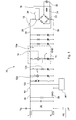
- Fig. 1 shows a conventional circuit arrangement for operating a household appliance using the example of a washing machine.
- a circuit arrangement usually includes a mains connection 36, connecting leads 38 connected to the mains connection, various consumers such as water pump 12a, aquastop valve 12b and heating 12c, a safety device 15 with door lock monitoring electronics 15a, only the input to the electronics being shown, and with a safety switch 14, and a motor controller 16 for a drive motor 30 of the washing machine drum.
- the drive motor 30 of a washing machine drum not be operated when the loading door of the washing machine is not locked.
- the door lock monitoring 15 ensures that when the door is unlocked, the motor control 16 and thus the drive motor 30 of the washing machine drum are disconnected from the mains connection 36 by automatically opening the safety switch 14.
- Accidental operation of the drive motor 30 of the washing machine drum, which represents a component endangering a user is thus not possible with unlocked and thus in particular when the loading door of the washing machine is open.
- Motor controller 16 includes a rectifier bridge 22 and a link capacitor 24 as well as a current limiting resistor (e.g., NTC or PTC resistor) 26 which limits the inrush current. This current limiting resistor 26 is then bridged by a relay 28 of the motor controller 16 to supply the drive motor 30 via the rectifier bridge 22, the energy required for operation.
- a current limiting resistor e.g., NTC or PTC resistor
- a communication between the engine controller 16 and a main controller 34 of the washing machine, for example via a bus system is not possible because the power supply of the motor controller 16 is interrupted by the safety switch 14.
- This means that communication of the engine control 16 with the main controller 34 of the washing machine is possible only after locking the loading door.
- a load sensor connected to the engine control 16 can be activated only after locking the loading door.
- a check of the loading quantity of the washing machine drum is cumbersome for the user since in each case the loading door first has to be locked before a loading value can be determined. If the maximum load has not yet been reached or exceeded, the user may have to open and close the loading door several times to optimize the load.
- the circuit arrangement according to the invention has a power supply connection; a load which is connected to the power supply terminal via a connecting lead; a hazardous component controller connected to the power supply terminal via a connecting lead; a switching means for turning on and off the controller disposed between the controller and the power supply terminal in the terminal line; and a safety device for disconnecting the control from the power supply terminal disposed between the power supply terminal and the switching means in the terminal line.
- the load is connected between the power supply connection and the safety device, and a connection line is provided which connects the control via the load to the power supply connection and in which a switching means is arranged.
- a consumer is connected via a connecting line to a power supply connection; a controller for the hazardous component is connectable via a connecting line to the power supply terminal; the controller is separable from the power supply terminal by means of a safety device arranged in the connection line; and in the case of disconnecting the controller from the power supply terminal by the security device, the controller is connected to the power supply terminal via a connection line via the load.
- a hazardous component e.g., washing machine drum drive motor
- a hazardous condition e.g., open loading door of the washing machine
- the control of the hazardous component is automatically disconnected from the power supply connection in such a hazardous state by means of a safety device in the connecting cable.
- the control of the hazardous component continues to be supplied with energy even in such a hazardous state of the device, but with a significantly lower energy level than is necessary for the operation of the hazardous component.
- the control of the hazardous component by means of an additional connecting line via a consumer, which is arranged in front of the safety device, connected to the power supply connection. Due to the power supply of the controller, it may also perform certain functions that require less power during a hazardous condition that prohibits the operation of the hazardous component.
- the controller may preferably continue to perform measurement tasks (e.g., the load state of a washing machine drum) and communicate with a main controller of the apparatus.
- the control of the hazardous component is powered by a consumer before it is turned on after the endangerment state, can be omitted in the control of a current limiting resistor and this bridging switching means, which in conventional circuit arrangements such as in Fig. 1 required are.
- the structure of the control can be simplified and the space requirement of the controller can be reduced.
- the control is to be integrated into the hazardous component (eg engine control integrated in the drive motor).
- the control is due to their reduced weight less sensitive to mechanical accelerations. This too is particularly advantageous if the control is to be integrated into the hazardous one.
- the term "consumer” in this context refers to any type of a preferably high-impedance consumer.
- the electrical resistance of the load reduces the power supplied via the connecting line to the control of the hazardous component so far that the energy is insufficient for operation of the hazardous component.
- the electrical resistance of the consumer reduces the current only so far that the control of the hazardous component sufficient energy for performing auxiliary functions is available.
- the consumer is preferably a consumer who is present in the device anyway.
- consumers preferably pumps, heaters, valves and the like in question.
- the circuit arrangement may of course also contain other consumers.
- hazardous component is to be understood as meaning a component of the device which may pose a hazard to the user of the device. These are, for example, moving or rotating components and their drives that are accessible to the user. Depending on the type of device, the hazardous component is a washing machine or dryer drum, a fan of an extractor hood, etc. and their drives or drive motors.
- the "safety device” in this context is intended to denote any type of device which is suitable for separating the control for the hazardous component as a function of a recognized hazardous state.
- the safety device is preferably a switching device, which is arranged in the connecting line between the controller and the power supply connection.
- the security device is preferably coupled to a safety device or integrated into one, which is designed to detect a hazardous condition.
- the safety device is, depending on the type of device, for example, an electronics for door lock monitoring, which monitors the locking state of a loading door, for example, a washing machine and causes the opening or closing of the safety device.
- connection line represents an electrically conductive connection with the power supply connection.
- connection line contains two lines which are each connected to a pole or connection of the power supply connection.
- the consumer and the controller can be connected to the power supply connection by means of the same connecting cable or by means of different connecting cables.
- switching means is intended in this context to denote any type of component or component which can be switched between at least two switching states.
- the switching means is configured to open or close an electrical connection or to switch between at least two electrical connection branches.
- Suitable switching means are in particular relays, transistors and the like.
- a switching function of the switching means in the connecting line is coupled to a switching function of the safety device in the connecting line.
- the control becomes then reconnected to the power supply connection via the connecting lead so that the controller is again connected to the power supply connection with low resistance and the hazardous component can be operated again.
- connection of the control via the load to the power supply terminal is interrupted in the event of the disconnection of the control from the power supply terminal by the safety device.
- the switching means in the connecting line and the switching means in the connecting line are integrated with each other or formed as a common switching means.
- This common switching means is preferably arranged in the connecting line between the controller and the power supply terminal and can switch between the two electrical connection branches connecting line and connecting line.
- a further switching means in the connecting line between the controller and the consumer is arranged in addition to the arranged in the connecting line switching means for switching on and off the controller.
- At least one diode is arranged in the connecting line between the controller and the consumer. This diode, which is connected in series with the consumer when the power supply to the controller via the connecting line, causes a pulsating direct current through the consumer, so that it can not be activated inadvertently in this circuit state.
- the controller has a rectifier bridge and a DC link capacitor connected in parallel thereto.
- This control is particularly suitable for hazardous components that must be supplied with direct current, such as DC motors and in particular brushless DC motors.
- the DC link capacitor is then charged by the consumer from the power supply terminal.
- the invention is also a household appliance with a circuit arrangement of the invention described above.
- the invention is preferably used in this context for household appliances such as washing machines, dryers, dishwashers, stoves, ovens, hoods, refrigerators, freezers and the like.
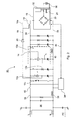
- the circuit arrangement of Fig. 2 includes a power supply connector 36, with which it can be connected to a power grid. With the poles of this power supply terminal, the two strands of a connecting line 38 are connected. In a wiring harness of the connection line 38 a main switch 40 is arranged for switching on and off the household appliance and its components.
- various consumers such as a water pump 12a, an aquastop valve 12b and a heater 12c are connected to the power supply terminal 36.
- the circuit arrangement further comprises a motor controller 16 for driving a drive motor 30 of the washing machine drum, which constitutes the hazardous component in the sense of the invention.
- the drive motor 30 is a preferably brushless DC motor.
- the motor controller 16 therefore has a rectifier bridge 22 and an intermediate circuit capacitor 24.
- the motor controller 16 is also connected via the connecting line 38 to the power supply terminal 36.
- a switching means 18 is arranged in the form of a relay in a connecting line of the connecting line 38 in order to turn the motor control on and off.
- the relay 18 may be arranged together with the engine control 16 on a power module. This power module can in turn be integrated in the drive motor 30.
- a main controller 34 of the household appliance is also provided. This is also connected to the connecting line 38. This main controller 34 is connected to the engine controller 16 via a signal line 35, for example in the form of a bus system.
- the engine controller 16 a sensor 32, which has, for example, a loading sensor for detecting a loading level of the washing machine drum.
- the measurement results of this sensor 32 can be communicated via the signal line 35 of the main controller 34 and evaluated by this and possibly displayed.
- a safety device 15 having an electronic door locking monitoring device 15a is further connected to the power supply connection 36. For clarity, only the input to the electronics of the door lock monitoring 15a is shown.
- the door lock monitor 15a monitors the locking state of the loading door of the washing machine.
- the safety device 15 further includes a safety device in the form of a safety switch 14, which is arranged in a wiring harness of the connection line 38 between the switching means 18 and the consumers 12a..c.
- the door lock monitor 15a detects a danger state in the form of an unlocked loading door of the washing machine, the door lock monitor 15a causes the opening of the safety switch 14 and interrupts the connection of the controller 16 via the connecting line 38 with the power supply terminal 36, so that the drive motor 30 by the controller 16 no longer can be operated.
- the opening and closing of the safety switch 14 is caused by the door lock monitor 15a by driving a solenoid in the door lock. If the loading door of the washing machine is closed, the safety switch 14 is automatically closed. The loading door is mechanically locked against opening.
- connection line 19 connects the motor control 16, bypassing the safety device 15 and in particular its safety switch 14 via one of the consumers (here the pump 12a) to the power supply connection 36.
- another consumer eg Aquastopp valve 12b or heater 12c .
- the consumer 12a is located in front of the safety switch 14, ie between the safety switch 14 and the main switch 40; Other consumers 12b, 12c, which are not connected to the connecting line 19, can optionally also circuitry behind the safety switch 14th be arranged.
- a switching means is arranged in the connecting line 19, . This switching means is either the relay 18 in the connecting line 38 for switching on and off of the engine control 16, which can switch between the connecting line 38 and the connecting line 19, or an additional relay 18a (variant shown in dashed lines) in the connecting line 19th
- the door lock monitor 15a checks whether the loading door of the washing machine is closed and locked or not. In the case of a locked loading door, the door lock monitor 15 closes the safety switch 14 in the connection line 38.
- the motor control 16 is thus connected via the connection line 38 to the power supply connection 36 and can be switched on via the relay 18 in the connection line 38. If the motor controller 16 is switched on via the relay 18, it is connected to the power supply connection 36 in a low-resistance manner and is supplied with sufficient energy by the latter in order to operate the sensor system 32 and in particular also the drive motor 30 of the washing machine drum.
- the safety switch 14 is opened, thus interrupting the electrical connection between the Motor control 16 and the power supply terminal 36. This interrupt occurs regardless of the circuit state of the relay 18th
- the relay 18 Since the motor control 16 is to be supplied with energy even in such a dangerous state in order to operate the sensor 32 and to communicate with the main controller 34, the relay 18 now switches over to the connecting line 19 (or the relay 18 is opened and the relay 18 a closed). In this way, the engine control 16 is opened Safety switch 14 via the connecting line 19 and the consumer 12 a connected to the power supply terminal 36.
- the motor control 16 can still operate the sensor system 32 even with an unlocked loading door.
- the loading door of the washing machine is open, the loading level can be detected and communicated to the main controller 34.
- the user can directly view the detected level of loading so that he can optimally load the washing machine drum.
- it does not have to open and close the loading door several times, but instead can complete its loading process directly when the loading door is open.
- a diode 20 is additionally connected in the connecting line 19 in series with the load 12a. Through this diode 20 results during charging of the intermediate circuit capacitor 24 via the connecting line 19, a pulsating direct current through the load 12a. This pulsating direct current prevents activation of this consumer 12a when switching on the device. Disturbing pumping noise can thus be avoided.
- the locked state of the loading door is detected by the door lock monitoring device 15a, which then closes the safety switch 14 again by activating the magnetic coil in the door lock.
- the relay 18 is switched back to the connecting line 38 (or the relay 18a opened and the relay 18 is closed), so that the pump 12a is connected in parallel to the motor controller 16 and the motor controller 16 and thus the drive motor 30 are again connected to the power supply terminal 36 low impedance. Unlocking the loading door can be detected at any time in this state by the door lock monitoring 15a.
Landscapes
- Engineering & Computer Science (AREA)
- Textile Engineering (AREA)
- Control Of Washing Machine And Dryer (AREA)
- Main Body Construction Of Washing Machines And Laundry Dryers (AREA)
- Detail Structures Of Washing Machines And Dryers (AREA)
Applications Claiming Priority (2)
| Application Number | Priority Date | Filing Date | Title |
|---|---|---|---|
| DE102011115502 | 2011-10-11 | ||
| DE102012016412A DE102012016412A1 (de) | 2011-10-11 | 2012-08-21 | Schaltungsanordnung und Verfahren zum Betreiben eines Haushaltungsgerätes |
Publications (2)
| Publication Number | Publication Date |
|---|---|
| EP2586901A1 true EP2586901A1 (fr) | 2013-05-01 |
| EP2586901B1 EP2586901B1 (fr) | 2017-03-15 |
Family
ID=47908950
Family Applications (1)
| Application Number | Title | Priority Date | Filing Date |
|---|---|---|---|
| EP12006898.6A Active EP2586901B1 (fr) | 2011-10-11 | 2012-10-04 | Circuit et procédé de fonctionnement d'un appareil ménager |
Country Status (4)
| Country | Link |
|---|---|
| US (1) | US9297105B2 (fr) |
| EP (1) | EP2586901B1 (fr) |
| CN (1) | CN103048945B (fr) |
| DE (1) | DE102012016412A1 (fr) |
Cited By (1)
| Publication number | Priority date | Publication date | Assignee | Title |
|---|---|---|---|---|
| WO2018015212A1 (fr) * | 2016-07-19 | 2018-01-25 | BSH Hausgeräte GmbH | Circuit de surveillance de porte pour un appareil électroménager |
Families Citing this family (6)
| Publication number | Priority date | Publication date | Assignee | Title |
|---|---|---|---|---|
| US20140015345A1 (en) * | 2012-07-10 | 2014-01-16 | iLumisys, Inc | Current limiting circuit for electrical devices |
| DE102014209112A1 (de) * | 2014-05-14 | 2015-11-19 | BSH Hausgeräte GmbH | Ventileinrichtung für ein Haushaltsgerät, Haushaltsgerät und entsprechendes Verfahren |
| CN108271279B (zh) * | 2018-02-12 | 2020-09-01 | 青岛海尔科技有限公司 | 干衣机的启动控制电路 |
| JP6666960B2 (ja) * | 2018-07-06 | 2020-03-18 | 株式会社チップトン | 遠心バレル研磨機及び遠心バレル研磨方法 |
| AU2019445898B2 (en) * | 2019-05-13 | 2026-01-22 | Electrolux Appliances Aktiebolag | Laundry-treating machine and method for controlling such a laundry-treating machine |
| CN113944039B (zh) * | 2020-07-15 | 2023-05-02 | 青岛海尔洗衣机有限公司 | 一种干衣机门锁控制方法及干衣机 |
Citations (5)
| Publication number | Priority date | Publication date | Assignee | Title |
|---|---|---|---|---|
| DE1916808A1 (de) * | 1969-03-28 | 1970-10-01 | Siemens Elektrogeraete Gmbh | Zum Schleudern eingerichtete Trommelwaschmaschine |
| EP0775463A2 (fr) * | 1995-11-21 | 1997-05-28 | Whirlpool Corporation | Lave-vaisselle et commande de celui-ci |
| WO2009007380A1 (fr) * | 2007-07-10 | 2009-01-15 | Elmarc Societa' Per Azioni | Système et circuit électronique utilisés pour protéger la porte de machines à laver ou de machines à laver sécheuses |
| DE102007031882A1 (de) * | 2007-07-09 | 2009-04-30 | Diehl Ako Stiftung & Co. Kg | Wäschebehandlungsgerät mit Türverriegelungselement |
| WO2009071413A1 (fr) * | 2007-12-05 | 2009-06-11 | BSH Bosch und Siemens Hausgeräte GmbH | Circuits pour faire fonctionner un appareil électroménager |
Family Cites Families (6)
| Publication number | Priority date | Publication date | Assignee | Title |
|---|---|---|---|---|
| JP2966461B2 (ja) * | 1990-03-09 | 1999-10-25 | 株式会社日立製作所 | 洗濯機の制御装置 |
| CN1164823C (zh) * | 2001-04-21 | 2004-09-01 | 海尔集团公司 | 套桶洗衣机 |
| CN2929948Y (zh) * | 2006-03-06 | 2007-08-01 | 孙迎光 | 一种触点大间隙低功耗电磁继电器 |
| DE102007037767A1 (de) * | 2007-02-26 | 2008-08-28 | Diehl Ako Stiftung & Co. Kg | Gerät mit ansteuerbarer Schutzeinrichtung |
| DE102007019102B4 (de) * | 2007-04-23 | 2009-01-22 | Diehl Ako Stiftung & Co. Kg | Steuervorrichtung und Steuerverfahren für ein elektrisches Haushaltsgerät |
| CN101858025A (zh) * | 2010-05-13 | 2010-10-13 | 合肥荣事达三洋电器股份有限公司 | 一种洗衣机的上电电路及其上电方法 |
-
2012
- 2012-08-21 DE DE102012016412A patent/DE102012016412A1/de not_active Withdrawn
- 2012-10-04 EP EP12006898.6A patent/EP2586901B1/fr active Active
- 2012-10-11 CN CN201210505132.0A patent/CN103048945B/zh active Active
- 2012-10-11 US US13/649,453 patent/US9297105B2/en active Active
Patent Citations (5)
| Publication number | Priority date | Publication date | Assignee | Title |
|---|---|---|---|---|
| DE1916808A1 (de) * | 1969-03-28 | 1970-10-01 | Siemens Elektrogeraete Gmbh | Zum Schleudern eingerichtete Trommelwaschmaschine |
| EP0775463A2 (fr) * | 1995-11-21 | 1997-05-28 | Whirlpool Corporation | Lave-vaisselle et commande de celui-ci |
| DE102007031882A1 (de) * | 2007-07-09 | 2009-04-30 | Diehl Ako Stiftung & Co. Kg | Wäschebehandlungsgerät mit Türverriegelungselement |
| WO2009007380A1 (fr) * | 2007-07-10 | 2009-01-15 | Elmarc Societa' Per Azioni | Système et circuit électronique utilisés pour protéger la porte de machines à laver ou de machines à laver sécheuses |
| WO2009071413A1 (fr) * | 2007-12-05 | 2009-06-11 | BSH Bosch und Siemens Hausgeräte GmbH | Circuits pour faire fonctionner un appareil électroménager |
Cited By (1)
| Publication number | Priority date | Publication date | Assignee | Title |
|---|---|---|---|---|
| WO2018015212A1 (fr) * | 2016-07-19 | 2018-01-25 | BSH Hausgeräte GmbH | Circuit de surveillance de porte pour un appareil électroménager |
Also Published As
| Publication number | Publication date |
|---|---|
| US9297105B2 (en) | 2016-03-29 |
| CN103048945B (zh) | 2017-07-18 |
| DE102012016412A1 (de) | 2013-04-11 |
| EP2586901B1 (fr) | 2017-03-15 |
| US20130088098A1 (en) | 2013-04-11 |
| CN103048945A (zh) | 2013-04-17 |
Similar Documents
| Publication | Publication Date | Title |
|---|---|---|
| EP2586901B1 (fr) | Circuit et procédé de fonctionnement d'un appareil ménager | |
| EP2567246B1 (fr) | Appareil ménager et procédé de contrôle d'une charge électrique d'un appareil ménager | |
| EP2217754B1 (fr) | Circuits pour faire fonctionner un appareil électroménager | |
| EP3706305A1 (fr) | Appareil électroménager et procédé de fonctionnement d'un appareil électroménager | |
| DE112019004927T5 (de) | Hochspannungsgerät-steuervorrichtung | |
| EP2085836A1 (fr) | Circuit et procédé pour faire fonctionner un appareil électroménager | |
| DE102007005881B3 (de) | Verfahren zum Betrieb eines Torantriebes und Torantrieb | |
| DE10222376A1 (de) | Elektromotorisch betriebenes Küchengerät | |
| DE69713455T2 (de) | Waschmaschine mit einer sofortwirkenden Türverriegelungsvorrichtung | |
| EP3726714B1 (fr) | Dispositif de filtre d4alimentation pour un appareil électroménager, appareil électroménager ainsi que procédé | |
| DE102007058380A1 (de) | Schaltungsanordnung zum Betreiben eines Hausgeräts | |
| DE102010028569A1 (de) | Haushaltsgerät und Verfahren zum Betreiben eines Haushaltsgerätes | |
| EP2517351B1 (fr) | Séparation du réseau électrique avec commutateurs pour outils électriques | |
| DE102010062522A1 (de) | Haushaltsgerät und Verfahren zum Schutz eines elektrischen Verbrauchers vor thermischer Überlast in einem Haushaltsgerät | |
| WO2012049116A1 (fr) | Circuit pour faire fonctionner une charge électrique, dispositif de commande pour commander un moteur d'entraînement d'un appareil électroménager, appareil électroménager et procédé pour faire fonctionner une charge électrique dans un appareil électroménager | |
| DE102019211281A1 (de) | System zum Betrieb einer Riegelvorrichtung | |
| DE19951747C1 (de) | Schaltung für einen Elektromotor | |
| DE102007009604A1 (de) | Haushaltgerät wie Spülmaschine, Waschmaschine, Trockner, Dunstabzugshaube oder Kühlschrank mit einem elektronisch kommutierten Motor | |
| WO2009130126A1 (fr) | Dispositif de fermeture de porte et procédé pour actionner ce dispositif | |
| DE102022119502A1 (de) | Gargerät | |
| DE4104887A1 (de) | Antriebseinrichtung fuer eine waschmaschinentrommel | |
| EP2667471B1 (fr) | Agencement de commutation destiné à la commande d'un consommateur électrique | |
| DE102018201382A1 (de) | Sicherheitssteuerung und Lastschalteinrichtung | |
| WO2009121814A1 (fr) | Circuit de commande d'au moins deux récepteurs électriques d'un appareil ménager et procédé correspondant | |
| DE102007048833B4 (de) | Ver- und Entriegelung eines Heizgeräts |
Legal Events
| Date | Code | Title | Description |
|---|---|---|---|
| PUAI | Public reference made under article 153(3) epc to a published international application that has entered the european phase |
Free format text: ORIGINAL CODE: 0009012 |
|
| AK | Designated contracting states |
Kind code of ref document: A1 Designated state(s): AL AT BE BG CH CY CZ DE DK EE ES FI FR GB GR HR HU IE IS IT LI LT LU LV MC MK MT NL NO PL PT RO RS SE SI SK SM TR |
|
| AX | Request for extension of the european patent |
Extension state: BA ME |
|
| 17P | Request for examination filed |
Effective date: 20130712 |
|
| RBV | Designated contracting states (corrected) |
Designated state(s): AL AT BE BG CH CY CZ DE DK EE ES FI FR GB GR HR HU IE IS IT LI LT LU LV MC MK MT NL NO PL PT RO RS SE SI SK SM TR |
|
| GRAP | Despatch of communication of intention to grant a patent |
Free format text: ORIGINAL CODE: EPIDOSNIGR1 |
|
| RIC1 | Information provided on ipc code assigned before grant |
Ipc: A47L 15/46 20060101ALI20160921BHEP Ipc: D06F 37/42 20060101AFI20160921BHEP |
|
| INTG | Intention to grant announced |
Effective date: 20161020 |
|
| GRAS | Grant fee paid |
Free format text: ORIGINAL CODE: EPIDOSNIGR3 |
|
| GRAA | (expected) grant |
Free format text: ORIGINAL CODE: 0009210 |
|
| AK | Designated contracting states |
Kind code of ref document: B1 Designated state(s): AL AT BE BG CH CY CZ DE DK EE ES FI FR GB GR HR HU IE IS IT LI LT LU LV MC MK MT NL NO PL PT RO RS SE SI SK SM TR |
|
| REG | Reference to a national code |
Ref country code: CH Ref legal event code: EP Ref country code: GB Ref legal event code: FG4D Free format text: NOT ENGLISH |
|
| REG | Reference to a national code |
Ref country code: IE Ref legal event code: FG4D Free format text: LANGUAGE OF EP DOCUMENT: GERMAN |
|
| REG | Reference to a national code |
Ref country code: AT Ref legal event code: REF Ref document number: 875685 Country of ref document: AT Kind code of ref document: T Effective date: 20170415 |
|
| REG | Reference to a national code |
Ref country code: DE Ref legal event code: R096 Ref document number: 502012009758 Country of ref document: DE |
|
| REG | Reference to a national code |
Ref country code: NL Ref legal event code: MP Effective date: 20170315 |
|
| REG | Reference to a national code |
Ref country code: LT Ref legal event code: MG4D |
|
| PG25 | Lapsed in a contracting state [announced via postgrant information from national office to epo] |
Ref country code: NO Free format text: LAPSE BECAUSE OF FAILURE TO SUBMIT A TRANSLATION OF THE DESCRIPTION OR TO PAY THE FEE WITHIN THE PRESCRIBED TIME-LIMIT Effective date: 20170615 Ref country code: LT Free format text: LAPSE BECAUSE OF FAILURE TO SUBMIT A TRANSLATION OF THE DESCRIPTION OR TO PAY THE FEE WITHIN THE PRESCRIBED TIME-LIMIT Effective date: 20170315 Ref country code: HR Free format text: LAPSE BECAUSE OF FAILURE TO SUBMIT A TRANSLATION OF THE DESCRIPTION OR TO PAY THE FEE WITHIN THE PRESCRIBED TIME-LIMIT Effective date: 20170315 Ref country code: GR Free format text: LAPSE BECAUSE OF FAILURE TO SUBMIT A TRANSLATION OF THE DESCRIPTION OR TO PAY THE FEE WITHIN THE PRESCRIBED TIME-LIMIT Effective date: 20170616 Ref country code: FI Free format text: LAPSE BECAUSE OF FAILURE TO SUBMIT A TRANSLATION OF THE DESCRIPTION OR TO PAY THE FEE WITHIN THE PRESCRIBED TIME-LIMIT Effective date: 20170315 |
|
| PG25 | Lapsed in a contracting state [announced via postgrant information from national office to epo] |
Ref country code: BG Free format text: LAPSE BECAUSE OF FAILURE TO SUBMIT A TRANSLATION OF THE DESCRIPTION OR TO PAY THE FEE WITHIN THE PRESCRIBED TIME-LIMIT Effective date: 20170615 Ref country code: SE Free format text: LAPSE BECAUSE OF FAILURE TO SUBMIT A TRANSLATION OF THE DESCRIPTION OR TO PAY THE FEE WITHIN THE PRESCRIBED TIME-LIMIT Effective date: 20170315 Ref country code: RS Free format text: LAPSE BECAUSE OF FAILURE TO SUBMIT A TRANSLATION OF THE DESCRIPTION OR TO PAY THE FEE WITHIN THE PRESCRIBED TIME-LIMIT Effective date: 20170315 Ref country code: LV Free format text: LAPSE BECAUSE OF FAILURE TO SUBMIT A TRANSLATION OF THE DESCRIPTION OR TO PAY THE FEE WITHIN THE PRESCRIBED TIME-LIMIT Effective date: 20170315 |
|
| PG25 | Lapsed in a contracting state [announced via postgrant information from national office to epo] |
Ref country code: NL Free format text: LAPSE BECAUSE OF FAILURE TO SUBMIT A TRANSLATION OF THE DESCRIPTION OR TO PAY THE FEE WITHIN THE PRESCRIBED TIME-LIMIT Effective date: 20170315 |
|
| REG | Reference to a national code |
Ref country code: FR Ref legal event code: PLFP Year of fee payment: 6 |
|
| PG25 | Lapsed in a contracting state [announced via postgrant information from national office to epo] |
Ref country code: SK Free format text: LAPSE BECAUSE OF FAILURE TO SUBMIT A TRANSLATION OF THE DESCRIPTION OR TO PAY THE FEE WITHIN THE PRESCRIBED TIME-LIMIT Effective date: 20170315 Ref country code: EE Free format text: LAPSE BECAUSE OF FAILURE TO SUBMIT A TRANSLATION OF THE DESCRIPTION OR TO PAY THE FEE WITHIN THE PRESCRIBED TIME-LIMIT Effective date: 20170315 Ref country code: RO Free format text: LAPSE BECAUSE OF FAILURE TO SUBMIT A TRANSLATION OF THE DESCRIPTION OR TO PAY THE FEE WITHIN THE PRESCRIBED TIME-LIMIT Effective date: 20170315 Ref country code: IT Free format text: LAPSE BECAUSE OF FAILURE TO SUBMIT A TRANSLATION OF THE DESCRIPTION OR TO PAY THE FEE WITHIN THE PRESCRIBED TIME-LIMIT Effective date: 20170315 Ref country code: ES Free format text: LAPSE BECAUSE OF FAILURE TO SUBMIT A TRANSLATION OF THE DESCRIPTION OR TO PAY THE FEE WITHIN THE PRESCRIBED TIME-LIMIT Effective date: 20170315 Ref country code: CZ Free format text: LAPSE BECAUSE OF FAILURE TO SUBMIT A TRANSLATION OF THE DESCRIPTION OR TO PAY THE FEE WITHIN THE PRESCRIBED TIME-LIMIT Effective date: 20170315 |
|
| PG25 | Lapsed in a contracting state [announced via postgrant information from national office to epo] |
Ref country code: IS Free format text: LAPSE BECAUSE OF FAILURE TO SUBMIT A TRANSLATION OF THE DESCRIPTION OR TO PAY THE FEE WITHIN THE PRESCRIBED TIME-LIMIT Effective date: 20170715 Ref country code: PL Free format text: LAPSE BECAUSE OF FAILURE TO SUBMIT A TRANSLATION OF THE DESCRIPTION OR TO PAY THE FEE WITHIN THE PRESCRIBED TIME-LIMIT Effective date: 20170315 Ref country code: SM Free format text: LAPSE BECAUSE OF FAILURE TO SUBMIT A TRANSLATION OF THE DESCRIPTION OR TO PAY THE FEE WITHIN THE PRESCRIBED TIME-LIMIT Effective date: 20170315 Ref country code: PT Free format text: LAPSE BECAUSE OF FAILURE TO SUBMIT A TRANSLATION OF THE DESCRIPTION OR TO PAY THE FEE WITHIN THE PRESCRIBED TIME-LIMIT Effective date: 20170717 |
|
| REG | Reference to a national code |
Ref country code: DE Ref legal event code: R097 Ref document number: 502012009758 Country of ref document: DE |
|
| PLBE | No opposition filed within time limit |
Free format text: ORIGINAL CODE: 0009261 |
|
| STAA | Information on the status of an ep patent application or granted ep patent |
Free format text: STATUS: NO OPPOSITION FILED WITHIN TIME LIMIT |
|
| PG25 | Lapsed in a contracting state [announced via postgrant information from national office to epo] |
Ref country code: DK Free format text: LAPSE BECAUSE OF FAILURE TO SUBMIT A TRANSLATION OF THE DESCRIPTION OR TO PAY THE FEE WITHIN THE PRESCRIBED TIME-LIMIT Effective date: 20170315 |
|
| 26N | No opposition filed |
Effective date: 20171218 |
|
| PG25 | Lapsed in a contracting state [announced via postgrant information from national office to epo] |
Ref country code: SI Free format text: LAPSE BECAUSE OF FAILURE TO SUBMIT A TRANSLATION OF THE DESCRIPTION OR TO PAY THE FEE WITHIN THE PRESCRIBED TIME-LIMIT Effective date: 20170315 |
|
| PG25 | Lapsed in a contracting state [announced via postgrant information from national office to epo] |
Ref country code: MC Free format text: LAPSE BECAUSE OF FAILURE TO SUBMIT A TRANSLATION OF THE DESCRIPTION OR TO PAY THE FEE WITHIN THE PRESCRIBED TIME-LIMIT Effective date: 20170315 |
|
| REG | Reference to a national code |
Ref country code: CH Ref legal event code: PL |
|
| GBPC | Gb: european patent ceased through non-payment of renewal fee |
Effective date: 20171004 |
|
| REG | Reference to a national code |
Ref country code: IE Ref legal event code: MM4A |
|
| PG25 | Lapsed in a contracting state [announced via postgrant information from national office to epo] |
Ref country code: GB Free format text: LAPSE BECAUSE OF NON-PAYMENT OF DUE FEES Effective date: 20171004 Ref country code: CH Free format text: LAPSE BECAUSE OF NON-PAYMENT OF DUE FEES Effective date: 20171031 Ref country code: LI Free format text: LAPSE BECAUSE OF NON-PAYMENT OF DUE FEES Effective date: 20171031 Ref country code: LU Free format text: LAPSE BECAUSE OF NON-PAYMENT OF DUE FEES Effective date: 20171004 |
|
| REG | Reference to a national code |
Ref country code: BE Ref legal event code: MM Effective date: 20171031 |
|
| PG25 | Lapsed in a contracting state [announced via postgrant information from national office to epo] |
Ref country code: BE Free format text: LAPSE BECAUSE OF NON-PAYMENT OF DUE FEES Effective date: 20171031 |
|
| PG25 | Lapsed in a contracting state [announced via postgrant information from national office to epo] |
Ref country code: MT Free format text: LAPSE BECAUSE OF FAILURE TO SUBMIT A TRANSLATION OF THE DESCRIPTION OR TO PAY THE FEE WITHIN THE PRESCRIBED TIME-LIMIT Effective date: 20170315 |
|
| REG | Reference to a national code |
Ref country code: FR Ref legal event code: PLFP Year of fee payment: 7 |
|
| PG25 | Lapsed in a contracting state [announced via postgrant information from national office to epo] |
Ref country code: IE Free format text: LAPSE BECAUSE OF NON-PAYMENT OF DUE FEES Effective date: 20171004 |
|
| REG | Reference to a national code |
Ref country code: AT Ref legal event code: MM01 Ref document number: 875685 Country of ref document: AT Kind code of ref document: T Effective date: 20171004 |
|
| PG25 | Lapsed in a contracting state [announced via postgrant information from national office to epo] |
Ref country code: AT Free format text: LAPSE BECAUSE OF NON-PAYMENT OF DUE FEES Effective date: 20171004 |
|
| PG25 | Lapsed in a contracting state [announced via postgrant information from national office to epo] |
Ref country code: HU Free format text: LAPSE BECAUSE OF FAILURE TO SUBMIT A TRANSLATION OF THE DESCRIPTION OR TO PAY THE FEE WITHIN THE PRESCRIBED TIME-LIMIT; INVALID AB INITIO Effective date: 20121004 |
|
| PG25 | Lapsed in a contracting state [announced via postgrant information from national office to epo] |
Ref country code: CY Free format text: LAPSE BECAUSE OF NON-PAYMENT OF DUE FEES Effective date: 20170315 |
|
| PG25 | Lapsed in a contracting state [announced via postgrant information from national office to epo] |
Ref country code: MK Free format text: LAPSE BECAUSE OF FAILURE TO SUBMIT A TRANSLATION OF THE DESCRIPTION OR TO PAY THE FEE WITHIN THE PRESCRIBED TIME-LIMIT Effective date: 20170315 |
|
| PGFP | Annual fee paid to national office [announced via postgrant information from national office to epo] |
Ref country code: FR Payment date: 20191028 Year of fee payment: 8 |
|
| PG25 | Lapsed in a contracting state [announced via postgrant information from national office to epo] |
Ref country code: TR Free format text: LAPSE BECAUSE OF FAILURE TO SUBMIT A TRANSLATION OF THE DESCRIPTION OR TO PAY THE FEE WITHIN THE PRESCRIBED TIME-LIMIT Effective date: 20170315 |
|
| PG25 | Lapsed in a contracting state [announced via postgrant information from national office to epo] |
Ref country code: AL Free format text: LAPSE BECAUSE OF FAILURE TO SUBMIT A TRANSLATION OF THE DESCRIPTION OR TO PAY THE FEE WITHIN THE PRESCRIBED TIME-LIMIT Effective date: 20170315 |
|
| PG25 | Lapsed in a contracting state [announced via postgrant information from national office to epo] |
Ref country code: FR Free format text: LAPSE BECAUSE OF NON-PAYMENT OF DUE FEES Effective date: 20201031 |
|
| PGFP | Annual fee paid to national office [announced via postgrant information from national office to epo] |
Ref country code: DE Payment date: 20241212 Year of fee payment: 13 |