EP2586540B1 - Spülanlage - Google Patents
Spülanlage Download PDFInfo
- Publication number
- EP2586540B1 EP2586540B1 EP12007007.3A EP12007007A EP2586540B1 EP 2586540 B1 EP2586540 B1 EP 2586540B1 EP 12007007 A EP12007007 A EP 12007007A EP 2586540 B1 EP2586540 B1 EP 2586540B1
- Authority
- EP
- European Patent Office
- Prior art keywords
- flushing
- conduit
- valve
- pressure
- fluid
- Prior art date
- Legal status (The legal status is an assumption and is not a legal conclusion. Google has not performed a legal analysis and makes no representation as to the accuracy of the status listed.)
- Active
Links
- 238000011010 flushing procedure Methods 0.000 title claims description 25
- 239000012530 fluid Substances 0.000 claims description 37
- 238000004140 cleaning Methods 0.000 claims description 27
- 239000007788 liquid Substances 0.000 claims description 21
- 230000008878 coupling Effects 0.000 claims description 5
- 238000010168 coupling process Methods 0.000 claims description 5
- 238000005859 coupling reaction Methods 0.000 claims description 5
- 239000012459 cleaning agent Substances 0.000 claims description 2
- 238000012423 maintenance Methods 0.000 claims 1
- XLYOFNOQVPJJNP-UHFFFAOYSA-N water Substances O XLYOFNOQVPJJNP-UHFFFAOYSA-N 0.000 description 19
- 239000012141 concentrate Substances 0.000 description 11
- 238000000034 method Methods 0.000 description 9
- 241000196324 Embryophyta Species 0.000 description 6
- 238000009530 blood pressure measurement Methods 0.000 description 4
- 238000004321 preservation Methods 0.000 description 4
- 239000002826 coolant Substances 0.000 description 3
- 238000001139 pH measurement Methods 0.000 description 3
- 239000000126 substance Substances 0.000 description 3
- 238000011109 contamination Methods 0.000 description 2
- 239000012809 cooling fluid Substances 0.000 description 2
- 230000035622 drinking Effects 0.000 description 2
- 238000001746 injection moulding Methods 0.000 description 2
- 238000009434 installation Methods 0.000 description 2
- 239000000203 mixture Substances 0.000 description 2
- 239000003755 preservative agent Substances 0.000 description 2
- 230000002335 preservative effect Effects 0.000 description 2
- 238000001223 reverse osmosis Methods 0.000 description 2
- 238000005496 tempering Methods 0.000 description 2
- 235000004443 Ricinus communis Nutrition 0.000 description 1
- 240000000528 Ricinus communis Species 0.000 description 1
- 239000000443 aerosol Substances 0.000 description 1
- 230000001580 bacterial effect Effects 0.000 description 1
- 239000011538 cleaning material Substances 0.000 description 1
- 150000001875 compounds Chemical class 0.000 description 1
- 230000003750 conditioning effect Effects 0.000 description 1
- 238000001816 cooling Methods 0.000 description 1
- 239000000645 desinfectant Substances 0.000 description 1
- 238000001514 detection method Methods 0.000 description 1
- 238000004090 dissolution Methods 0.000 description 1
- 238000009296 electrodeionization Methods 0.000 description 1
- 239000000945 filler Substances 0.000 description 1
- 238000010438 heat treatment Methods 0.000 description 1
- 230000002262 irrigation Effects 0.000 description 1
- 238000003973 irrigation Methods 0.000 description 1
- 244000144972 livestock Species 0.000 description 1
- 238000004519 manufacturing process Methods 0.000 description 1
- 239000003550 marker Substances 0.000 description 1
- 239000002245 particle Substances 0.000 description 1
- 238000010926 purge Methods 0.000 description 1
- 230000008929 regeneration Effects 0.000 description 1
- 238000011069 regeneration method Methods 0.000 description 1
- 230000001105 regulatory effect Effects 0.000 description 1
- 239000012465 retentate Substances 0.000 description 1
- 231100000331 toxic Toxicity 0.000 description 1
- 230000002588 toxic effect Effects 0.000 description 1
- 239000012498 ultrapure water Substances 0.000 description 1
- 238000005406 washing Methods 0.000 description 1
Images

Classifications
-
- B—PERFORMING OPERATIONS; TRANSPORTING
- B08—CLEANING
- B08B—CLEANING IN GENERAL; PREVENTION OF FOULING IN GENERAL
- B08B9/00—Cleaning hollow articles by methods or apparatus specially adapted thereto
- B08B9/02—Cleaning pipes or tubes or systems of pipes or tubes
- B08B9/027—Cleaning the internal surfaces; Removal of blockages
- B08B9/032—Cleaning the internal surfaces; Removal of blockages by the mechanical action of a moving fluid, e.g. by flushing
- B08B9/0321—Cleaning the internal surfaces; Removal of blockages by the mechanical action of a moving fluid, e.g. by flushing using pressurised, pulsating or purging fluid
- B08B9/0328—Cleaning the internal surfaces; Removal of blockages by the mechanical action of a moving fluid, e.g. by flushing using pressurised, pulsating or purging fluid by purging the pipe with a gas or a mixture of gas and liquid
-
- B—PERFORMING OPERATIONS; TRANSPORTING
- B08—CLEANING
- B08B—CLEANING IN GENERAL; PREVENTION OF FOULING IN GENERAL
- B08B9/00—Cleaning hollow articles by methods or apparatus specially adapted thereto
- B08B9/02—Cleaning pipes or tubes or systems of pipes or tubes
- B08B9/027—Cleaning the internal surfaces; Removal of blockages
- B08B9/032—Cleaning the internal surfaces; Removal of blockages by the mechanical action of a moving fluid, e.g. by flushing
- B08B9/0321—Cleaning the internal surfaces; Removal of blockages by the mechanical action of a moving fluid, e.g. by flushing using pressurised, pulsating or purging fluid
- B08B9/0325—Control mechanisms therefor
Definitions
- the invention relates to a flushing device for cleaning a fluid system.
- the chemical and / or biological contamination of the aqueous cooling agents used for tempering contaminates the liquid-wetted surfaces of the fluid system with the serious disadvantage of a poor temperature control, due to the poor heat transfer.
- DE 201 02 946 U1 discloses a device for cleaning a water and drinking line in the livestock industry.
- the device has a liquid container from which a so-called domestic water plant sucks in cleaning liquid, the domestic water plant adjusts a water pressure.
- This water pressure is displayed at the house waterworks by a manometer. Downstream of a subsequent non-return valve, a compressed-air line opens into the line carrying the cleaning fluid. The pressure of the air-water disinfectant mixture is then displayed on a manometer. This is followed by two ball valves downstream with connections to two water and drinking lines, which are to be cleaned.
- a backwash line leads at the end of the water and Tränketechnischen back to the liquid container.
- shockwashing machine of the US 2003/0051746 A1 opens a compressed air line in a recirculation line.
- two pressure measuring devices are provided in the compressed air line to monitor the pressure in this line.
- the cleaning device of WO2005 / 105331 A1 the pressure within the pipes to be cleaned is monitored by arranging a pipe section with two valves on both sides of a pressure measuring device.
- the present invention has for its object to provide a rinsing system for cleaning a fluid system that is structurally simple and avoids the above disadvantages.
- the system according to the invention is connected to the fluid system. Especially in stationary facilities such. Heat exchangers or heavy molds is advantageously used a mobile system with flexible flushing hoses.
- the rinsing system is first brought into spatial proximity of the fluid system and connected there by means of couplings.
- the plant includes in the basic version a rinsing tank or tank, a circulation pump, at least one non-return and another pressure-holding valve, and preferably a compressed air supply and a filter installed in the circulation circuit.
- the system is mounted on a mobile platform.
- the rinsing tubes can be rolled up on castors with retraction.
- the system can be equipped with a simple dosing system, which consists of a Venturi pump, a Conductivity and / or pH measurement and a connected cleaning concentrate can be extended.
- the tank is filled with a rinsing liquid consisting of a carrier liquid, e.g. Water and a proportioned rinse or preservative concentrate is filled.
- a carrier liquid e.g. Water
- a proportioned rinse or preservative concentrate is filled.
- air can be introduced into the cleaning circuit in a continuous or pulsed manner for the dissolution of crystalline residues in the fluid system.
- thermal support of the cleaning process by a heater.
- the spent flushing liquid can be conveyed by the introduced air from the fluid system and the connected lines back into the tank to use them again by means of a treatment system, or to promote in a treatment tank or simply discard it in a drain.
- the plant is advantageously combined with both a water treatment plant, as well as with a plant for the treatment of spent rinse liquid.
- the system of the invention is easy to use and hygienic.
- the flexible connections can be plugged after cleaning to a parking station.
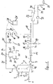
- FIG. 1 shows a fully equipped cleaning system, which is connected via the connection (1), the water inlet valve (2) and the flow meter or water meter (3) to a water supply or not shown here water treatment system.
- the conditioning filter (32) with its components is shown as a possible option for clarity.
- the supplied liquid flows into the washing container (4) until the flow meter (3) or also the level sensors (5) signal the end of the feed.
- circulation pump (9) By means of circulation pump (9), the liquid is conveyed through the flushing line (8), which has two line sections (8a) and (8b).
- the circulation pump (9) can be used both air and electrically operated. Before starting the cleaning of the fluid system (20), all connections of the system can be physically or chemically cleaned. This is possible both via the heater (11) and via an ozone cell or flushing concentrate (29), not shown here.
- valve (31) is closed, the pressure-controlled air supply (17) opened and briefly put pressure on the compounds. If the valve (10) is not a check valve - as is preferred - but a normal shut-off valve, this is also closed. If the pressure drop monitored by the pressure measurement (16) remains within a specified limit, the connections are considered tight.
- the pressure holding test can also be carried out with liquid. For this is filled tank (4) the Pump (9) started briefly, the valve (31) remains closed. The pressure holding test is monitored by means of pressure measurement (16). With manual dosing, the desired amount of liquid is supplied to the tank (4) either via the lid (7) or the downstream flushing hose (19) until the mark at marking (42) is reached. Thereafter, the rinsing concentrate is added manually.
- the dosing of the rinsing concentrate takes place in a system with dosing system via a venturi pump (24) and the opened concentrate valve (25).
- the aspiration process is monitored by conductivity and / or pH measurement and is terminated when a predetermined concentration has been reached.
- the flushing hoses (19) with the couplings (28) are coupled to the connections of the fluid system (20).
- the rinsing tubes (19) are rolled up on rollers with retraction (45) and are pulled out of the rinsing system for connection or automatically rolled up after use and, if necessary, put on the parking station (18).
- the pump (9) circulates the rinsing liquid out of the container (4) via the fluid system (20), the filter (21) into the rinsing line (8). Detached particles remain in the filter (21) and must be rinsed cyclically by means of a filter rinse valve (22).
- the check valve (15) can be opened manually for this purpose.
- the rinsing liquid can be emptied via the drain valve (14) or, if the treatment filter (32) is present, partially supplied to a regeneration tank.
- the liquid is displaced from the fluid system (20) and the lines (19) by means of air.
- a preservation with the preservation concentrate (27) can be carried out after cleaning and emptying of the container (4). This process is identical to the rinsing process. Both the cleaning concentrate (29) and the preservation concentrate container (27) can be provided with a fill level monitor (30).
- the water meters (3/37) can be used to verify fluid balance.
- FIG. 2 shows, use highly pure, residue-free liquid as a carrier liquid.
- the rinsing system is preferably connected to the connection (1) to a reverse osmosis.
- additional treatment steps after reverse osmosis such as electrodeionization and / or additional filter stages.
- the high-purity rinsing liquid is conveyed in this application to the cleaning material introduced into a high-purity fluid chamber (43).
- the supply of the cleaning fluid takes place via a sterile filter (38) whose functionality is tested by supplying air into the primary circuit (38a).
Landscapes
- Engineering & Computer Science (AREA)
- Mechanical Engineering (AREA)
- Cleaning By Liquid Or Steam (AREA)
Description
- Die Erfindung betrifft eine Spülvorrichtung zum Reinigen eines Fluidsystems.
- Bei vielen industriellen Prozessen werden erhöhte Temperaturen benötigt, oder es entstehen hohe Temperaturen. Durch Hinzunahme eines Kühlmittels werden diese Temperaturen reguliert bzw. der Prozess gekühlt. Beispiele dafür sind Werkzeugformen für Spritzgussmaschinen, die in der Regel Fluidkanäle zum temperieren der Werkzeuge aufweisen. Auch Wärmetauscher wie z.B. Rohr-, Platten- oder Spiralwärmetauscher sind im Sinne des Oberbegriffs solche Fluidsysteme.
- Die chemische und oder auch biologische Verunreinigung der zur Temperierung eingesetzten wässrigen Kühlmittel kontaminiert je nach Gebrauchsdauer die flüssigkeitsbenetzten Oberflächen des Fluidsystems mit dem gravierenden Nachteil einer mangelhaften Temperaturregelung, bedingt durch den schlechten Wärmeübergang.
- Eine Vielzahl von Veröffentlichungen beschreibt die physikalische oder chemische Selbstreinigung der Kühlmittel. Je nach Prozesstemperatur, Aufbau des Fluidsystems, Strömungsgeschwindigkeit des Kühlfluids und Art des Kühlfluids ist die physikalische oder chemische Selbstreinigung auch hinsichtlich bakterieller Ablagerungen nicht sehr erfolgreich.
- Insbesondere teure Werkzeugformen für Spritzgussmaschinen können durch verunreinigte Kühlbohrungen ausfallen, bzw. die Prozesssicherheit erheblich gefährden. Die Verunreinigung von Wärmetauschern reduziert deren Effizienz und ebenso deren Prozesssicherheit.
-
DE 201 02 946 U1 offenbart eine Einrichtung zum Reinigen einer Wasser- und Tränkeleitung in der Viehwirtschaft. Die Einrichtung hat einen Flüssigkeitsbehälter, aus der ein sogenanntes Hauswasserwerk Reinigungsflüssigkeit ansaugt, wobei das Hauswasserwerk einen Wasserdruck einstellt. Dieser Wasserdruck wird an dem Hauswasserwerk durch ein Manometer angezeigt. Stromabwärts eines nachfolgenden Rückflussverhinderers mündet eine Druckluftleitung in die die Reinigungsflüssigkeit führende Leitung ein. Der Druck des Luft-Wasser-Desinfektionsmittel-Gemischs wird anschließend an einem Manometer angezeigt. Es folgen stromabwärts zwei Kugelhähne mit Verbindungen zu zwei Wasser- und Tränkeleitungen, die gereinigt werden sollen. Eine Rückspülleitung führt am Ende der Wasser- und Tränkeleitungen zu dem Flüssigkeitsbehälter zurück. - Bei der Stoßwasser-Reinigungsmaschine der
US 2003/0051746 A1 mündet eine Druckluftleitung in eine Rezirkulationsleitung ein. Dabei sind in der Druckluftleitung zwei Druckmesseinrichtungen vorgesehen, um den Druck in dieser Leitung zu überwachen. Bei der Reinigungsvorrichtung derWO2005/105331 A1 wird der Druck innerhalb der zu reinigenden Rohrleitungen überwacht, indem ein Rohrabschnitt mit zwei Ventilen beidseitig einer Druckmesseinrichtung angeordnet ist. - Der vorliegenden Erfindung liegt die Aufgabe zugrunde, eine Spülanlage zur Reinigung eines Fluidsystems zu schaffen, die konstruktiv einfach ist und die die obigen Nachteile vermeidet.
- Diese Aufgabe wird durch die Merkmale des Anspruchs 1 gelöst.
- Vorteilhafte Ausgestaltungen der Erfindung sind in den Unteransprüchen gekennzeichnet.
- Die erfindungsgemäße Anlage wird an das Fluidsystem konnektiert. Insbesondere bei stationären Einrichtungen wie z.B. Wärmetauschern oder schweren Werkzeugformen wird mit Vorteil eine mobile Anlage mit flexiblen Spülschläuchen eingesetzt. Die Spülanlage wird zunächst in räumlicher Nähe des Fluidsystems gebracht und dort mittels Kupplungen konnektiert.
- Eine stationäre Installation ist dadurch nicht ausgeschlossen.
- Die Anlage beinhaltet in der Basisausführung einen Spülbehälter oder Tank, eine Zirkulationspumpe, wenigstens ein Rückschlag- und ein weiteres Druckhalteventil, sowie vorzugsweise eine Druckluftzuführung und einen in dem Zirkulationskreislauf installierten Filter. Vorteilhafterweise ist die Anlage auf einer fahrbaren Plattform montiert. Aus Gründen der Übersichtlichkeit, Ordnung und Mobilität können die Spülschläuche dabei auf Rollen mit Rückzug aufgerollt sein.
- Zur automatischen Zudosierung von Reinigungsmitteln kann die Anlage mit einem einfachen Dosiersystem, welches aus einer Venturipumpe, einer
Leitfähigkeits- und/oder pH-Wertmessung sowie einen angeschlossenen Reinigungskonzentrat bestehen kann, erweitert werden. - Falls kein Dosiersystem vorhanden ist, wird der Tank mit einer Spülflüssigkeit, die aus einer Trägerflüssigkeit wie z.B. Wasser und einem proportioniertem Spül- oder Konservierungskonzentrat besteht, gefüllt.
- Da es sich in der Regel um aggressive, gesundheitsschädliche Reinigungsflüssigkeiten handelt, wird zu Beginn ein Druckhaltest mittels Luft oder auch Spülflüssigkeit durchgeführt, um spätere Leckagen oder Diskonnektionen zu vermeiden.
- Mit Vorteil kann während der Reinigung kontinuierlich oder impulsartig Luft zur Auflösung kristalliner Rückstände im Fluidsystem in den Reinigungskreislauf eingebracht werden. Zusätzlich besteht die Möglichkeit einer thermischen Unterstützung des Reinigungsprozesses durch eine Heizung.
- Zum Abschluss einer Reinigung besteht mit Vorteil die Möglichkeit, ein Konservierungsmittel in den Spültank einzubringen, oder mittels Luft das Fluidsystem zu trocken, oder auch eine Aerosolemischung in das Fluidsystem zu fördern. Dabei kann die verbrauchte Spülflüssigkeit durch die eingebrachte Luft aus dem Fluidsystem und den angeschlossenen Leitungen zurück in den Tank gefördert werden, um sie mittels eines Aufbereitungssystem wieder zu verwenden, oder in einen Aufbereitungsbehälter zu fördern oder sie ganz einfach in einen Abfluss zu verwerfen.
- Dabei ist die Anlage vorteilhafterweise sowohl mit einer Wasseraufbereitungsanlage, als auch mit einer Anlage zur Aufbereitung verbrauchter Spülflüssigkeit zu kombinieren.
- Die erfindungsgemäße Anlage ist einfach zu bedienen und hygienisch einwandfrei. Dazu können die flexiblen Anschlüsse nach beendeter Reinigung auf eine Parkstation gesteckt werden.
- Damit erfüllt diese Anlage nicht nur wirtschaftlich, sondern auch umweltkonforme Ansprüche.
-
Figur 1 zeigt eine vollausgestattete Reinigungsanlage, die über den Anschluss (1), das Wassereingangsventil (2) und den Flussmesser oder auch Wasseruhr (3) an eine Wasserversorgung oder ein hier nicht dargestelltes Wasseraufbereitungssystem angeschlossen ist. Der Aufbereitungsfilter (32) mit seinen Komponenten ist nur der Übersichtlichkeit als mögliche Option dargestellt. - Die zugeführte Flüssigkeit fließt so lange in den Spülbehälter (4), bis der Flussmesser (3) oder auch die Niveausensoren (5) das Ende der Zuführung signalisieren. Mittels Zirkulationspumpe (9) wird die Flüssigkeit durch die Spülleitung (8) gefördert, die zwei Leitungsabschnitte (8a) und (8b) hat. Die Zirkulationspumpe (9) kann sowohl luft- als auch elektrobetrieben eingesetzt werden. Vor Reinigungsbeginn des Fluidsystems (20) können alle Anschlüsse der Anlage physikalisch oder chemisch gereinigt werden. Dies ist sowohl über die Heizung (11) als auch über eine hier nicht dargestellte Ozonzelle oder das Spülkonzentrat (29) möglich.
- Vor Reinigungsbeginn des Fluidsystems (20) werden alle Anschlüsse der Anlage insbesondere aber die Kupplungen (28) der Spülschläuche (19) einem Druckhaltetest unterzogen. Dazu wird Ventil (31) geschlossen, die druckgeregelte Luftzufuhr (17) geöffnet und kurz Druck auf die Verbindungen gegeben. Wenn das Ventil (10) kein Rückschlagventil ist - wie dies bevorzugt ist - sondern ein normales Absperrventil, wird dieses ebenfalls geschlossen. Bleibt der von der Druckmessung (16) überwachte Druckabfall innerhalb einer festgelegten Grenze, gelten die Anschlüsse als dicht. Der Druckhaltetest kann auch mit Flüssigkeit durchgeführt werden. Dazu wird bei gefülltem Tank (4) die Pumpe (9) kurz gestartet, das Ventil (31) bleibt geschlossen. Der Druckhaltetest wird mittels Druckmessung (16) überwacht.
Bei manueller Dosierung wird die gewünschte Flüssigkeitsmenge dem Tank (4) entweder über den Deckel (7) oder den stromabwärts liegenden Spülschlauch (19) zugeführt, bis die Marke an Markierung (42) erreicht ist. Danach wird das Spülkonzentrat manuell zugegeben. - Die Dosierung des Spülkonzentrates erfolgt bei einer Anlage mit Dosiersystem über eine Venturipumpe (24) und das geöffnete Konzentratventil (25). Der Ansaugvorgang wird durch Leitfähigkeits- und oder auch pH-Messung überwacht und wird beendet, wenn eine vorgegebene Konzentration erreicht wurde.
- Zur Reinigung des Fluidsystems (20) werden die Spülschläuche (19) mit den Kupplungen (28) an die Anschlüsse des Fluidsystems (20) angekoppelt. Je nach räumlicher Entfernung zum Fluidsystem (20) sind die Spülschläuche (19) auf Rollen mit Rückzug (45) aufgerollt und werden zur Konnektion aus der Spülanlage herausgezogen bzw. nach Gebrauch automatisch eingerollt und ggf. auf die Parkstation (18) gesteckt.
- Die Pumpe (9) zirkuliert die Spülflüssigkeit aus dem Behälter (4) über das Fluidsystem (20), den Filter (21) in die Spülleitung (8). Abgelöste Partikel verbleiben im Filter (21) und sind zyklisch mittels Filterspülventil (22) auszuspülen.
- Zur Erhöhung des Förderdruckes bzw. des Fördervolumens besteht die Möglichkeit, bei luftbetriebenen Pumpenantrieben den Luftdruck am Pumpenantrieb zu erhöhen, Bei elektrisch betriebenen Antrieben kann dazu das Sperrventil (15) manuell geöffnet werden.
- Zur Erhöhung der Reinigungseffizienz durch Kavitation im Fluidsystem (20) kann kontinuierlich oder zyklisch Luft auch unterschiedlicher Drücke über den Luftanschluss (17) zugeführt werden.
- Nach der Beendigung eines Reinigungsvorgangs kann die Spülflüssigkeit über das Abflussventil (14) entleert oder bei vorhandenem Aufbereitungsfilter (32) teilweise einem Wiederaufbereitungstank zugeführt werden. Zur Entleerung des Fluidsystems (20) wird mittels Luft die Flüssigkeit aus dem Fluidsystem (20) und den Leitungen (19) verdrängt.
- Bei gewünschter Konservierung des Fluidsystems (20) kann nach erfolgter Reinigung und Entleerung des Behälters (4) eine Konservierung mit dem Konservierungskonzentrat (27) durchgeführt werden. Dieser Vorgang ist identisch mit dem Spülprozess. Sowohl der Reinigungskonzentrat- (29) als auch der Konservierungskonzentratbehälter (27) können mit einer Füllstandsüberwachung (30) versehen werden.
- Falls es sich bei der Spülflüssigkeit um toxische Stoffe handelt, können die Wasseruhren (3/37) zum Nachweis der Flüssigkeitsbilanz herangezogen werden.
- Bei Fluidsystem mit Volumen, die größer als das Tankvolumen sind, ist es erforderlich ggf. nachzudosieren und den Spülkreislauf (8) vom atmosphären Druck zu trennen. Dazu wird Tanküberlauf (6) geschlossen. Bei Überschreitung eines vorgegebenen max. zulässige Systemdrucks an der Messstelle (13) kann das Abflussventil (14) zum Druckausgleich geöffnet werden.
- Bei hygienisch anspruchsvollen Anwendungen besteht auch die Möglichkeit, wie
Figur 2 zeigt, hochreine, rückstandfreie Flüssigkeit als Trägerflüssigkeit einzusetzen. Dazu wird die Spülanlage am Anschluss (1) vorzugsweise an eine Umkehrosmose angeschlossen. Zur weiteren Verbesserung der Wasserqualität ist die Hinzunahme weiterer Aufbereitungsstufen nach der Umkehrosmose wie z.B. Elektrodenionisation und/oder zusätzliche Filterstufen möglich. - Diese mit einer hochreinen Wasseraufbereitung kombinierte Spülanlage ist sowohl zur äußeren als auch zur inneren Reinigung hygienisch anspruchsvoller Komponenten einsetzbar. Die hochreine Spülflüssigkeit wird bei dieser Applikation zu dem in einer hochreinen Fluidkammer (43) eingebrachten Reinigungsgut gefördert. Die Zuführung des Reinigungsfluids erfolgt hierbei über einen Sterilfilter (38), dessen Funktionalität durch Luftzuführung in den Primärkreis (38a) getestet wird.
- Über eine Absaugpumpe 41 wird das sich ansammelnde Reinigungsfluid abgepumpt.
- Da es sich bei dieser Ausführung in der Regel um stationäre Anlagen handelt, erfolgt die Aufbereitung der Spülflüssigkeit vorzugsweise mittels eines Dosiersystems nach dem bereits beschriebenen Ablauf aus
Figur 1 .Legende 1. Wasserzulauf 2. Wasserzulaufventil 3. Flussmesser/ Wasseruhr 4. Spülbehälter 5. Niveausensor 6. Tanküberlauf mit Ventil 7. Tankdeckel 8. Spülleitung 9. Zirkulationspumpe 10 Ventil, vorzugsweise Rückschlagventil 11 Heizung mit Temperatursensoren 12 Leitfähigkeits- und oder auch pH Messung 13 Druckmessung 14 Abflussventil 15 Sperrventil 16 Druckmessung 17 Luftzufuhr 18 Schlauchparkstation 19 Spülschläuche 20 Fluidsystem 21 Schmutzfilter 22 Filterspülventil 23 Drainage 24 Venturipumpe 25 Konzentratventil 26 Konservierungsventil 27 Konservierungskonzentratbehälter 28 Kupplungen 29 Spülkonzentratbehälter 30 Leererkennung 31 Ventil 32 Aufbereitungsfilter 33 Überströmpumpe 34 Strömungswiderstand 35 Bypassventil 36 Retentatventil 37 Retentatwasseruhr 38 Sterilfilter 39 Sterilflüssigkeitszuführung 40 Spülsystem 41 Absaugpumpe 42 Tankmarkierung 43 Hochreine Fluidkammer 44 Sterilfilter 45 Schlauchrollen mit Rückzug
Claims (3)
- Spülvorrichtung zum Reinigen von Fluidsystemen, mit einer Spülleitung (8), in die ein Spülbehälter (4) mit einem Tanküberlauf (6), der beim Nachdosieren von Spülflüssigkeit schließbar ist, und eine Zirkulationspumpe (9) integriert sind, wobei die Spülleitung zwei Spülleitungsabschnitte (8a, 8b) aufweist, deren Enden mit zwei Spülschläuchen (19) verbunden sind, deren Enden mit Kupplungen (28) versehen sind, die mit Fluidkanälen eines Fluidsystems koppelbar sind, so dass die Fluidkanäle in einen Zirkulationskreislauf eingeschlossen sind,
wobei in einen Spülleitungsabschnitt (8a) in Strömungsrichtung hintereinander die Zirkulationspumpe (9), ein Ventil (10), ein abzweigendes Abflussventil (14) und ein Sperrventil (15) integriert sind, gefolgt von der Einmündung einer Druckluftleitung (17),
wobei das Abflussventil (14) bei Überschreitung eines vorgegebenen maximalen Systemdrucks an einer Meßstelle (13) zum Druckausgleich geöffnet werden kann,
wobei in den anderen Spülleitungsabschnitt (8b) ein weiteres Ventil (31) integriert ist und
wobei zwischen den Ventilen (15,31) in einen der Spülleitungsabschnitte (8a oder 8b) eine Druckmessung (16) eingebaut ist, die geeignet ist, mittels Luft oder Spülflüssigkeit die Kupplungen einem Druckhaltetest zu unterziehen. - Spülvorrichtung nach Anspruch 1,
dadurch gekennzeichnet,
dass in die Zirkulationskreislaufleitung ein Filter (21) integriert ist. - Spülvorrichtung nach den Ansprüchen 1 oder 2,
dadurch gekennzeichnet,
dass die Zirkulationskreislaufleitung mit einer Einrichtung (24) zum Zudosieren von Reinigungsmitteln versehen ist.
Applications Claiming Priority (1)
| Application Number | Priority Date | Filing Date | Title |
|---|---|---|---|
| DE102011117060A DE102011117060A1 (de) | 2011-10-27 | 2011-10-27 | Spülanlage |
Publications (2)
| Publication Number | Publication Date |
|---|---|
| EP2586540A1 EP2586540A1 (de) | 2013-05-01 |
| EP2586540B1 true EP2586540B1 (de) | 2019-01-02 |
Family
ID=47046326
Family Applications (1)
| Application Number | Title | Priority Date | Filing Date |
|---|---|---|---|
| EP12007007.3A Active EP2586540B1 (de) | 2011-10-27 | 2012-10-09 | Spülanlage |
Country Status (2)
| Country | Link |
|---|---|
| EP (1) | EP2586540B1 (de) |
| DE (1) | DE102011117060A1 (de) |
Families Citing this family (6)
| Publication number | Priority date | Publication date | Assignee | Title |
|---|---|---|---|---|
| CN104941965B (zh) * | 2014-03-28 | 2017-06-30 | 中国二十冶集团有限公司 | 一种预防油品乳化的液压管道在线冲洗装置及冲洗方法 |
| DE102014015909B4 (de) | 2014-10-29 | 2020-01-02 | Dräger Safety AG & Co. KGaA | Wartungsvorrichtung und Verfahren zum Warten eines Kreislaufatemgerätes |
| CN104965504A (zh) * | 2015-07-27 | 2015-10-07 | 曼瑞德集团有限公司 | 具有制水保鲜、滤芯系统自清洗维护水路工艺及控制系统 |
| CN108262314A (zh) * | 2018-01-17 | 2018-07-10 | 山东钢铁集团日照有限公司 | 液压管道高效冲洗方法 |
| CN109550750B (zh) * | 2018-12-11 | 2020-11-06 | 方祥杰 | 一种石灰水管道的清理方法 |
| WO2021067557A1 (en) * | 2019-10-03 | 2021-04-08 | Abiomed, Inc. | Cleaning system for diaphragm pump |
Family Cites Families (7)
| Publication number | Priority date | Publication date | Assignee | Title |
|---|---|---|---|---|
| WO1988003065A1 (en) * | 1986-10-23 | 1988-05-05 | Sundholm Goeran | An apparatus for flushing small-diameter hydraulic pipe systems and the like |
| FR2757088B1 (fr) * | 1996-12-13 | 1999-01-15 | Rech Et De Formation Pourl Ass | Procede et unite de nettoyage de cuves |
| DE20102946U1 (de) * | 2001-02-13 | 2001-06-07 | Eggebrecht Horst | Einrichtung zum Reinigen von Rohrleitungen, insbesondere von Wasser- und Tränkeleitungen in der Viehwirtschaft |
| US6564816B2 (en) * | 2001-09-20 | 2003-05-20 | Asia Union Co., Ltd. | Water hammer cleaning machine |
| US7198052B2 (en) * | 2004-03-12 | 2007-04-03 | General Electric Company | Mobile flushing unit and process |
| US20090014036A1 (en) * | 2004-05-05 | 2009-01-15 | Whirlwind By-Air Limited | Clearing pipework in oil refineries and other plant having extensive pipework |
| EP1609540A2 (de) * | 2004-06-25 | 2005-12-28 | Adisa Service und Entwicklungs AG | Verfahren zur Behandlung einer zu reinigenden Rohrleitung |
-
2011
- 2011-10-27 DE DE102011117060A patent/DE102011117060A1/de not_active Withdrawn
-
2012
- 2012-10-09 EP EP12007007.3A patent/EP2586540B1/de active Active
Non-Patent Citations (1)
| Title |
|---|
| None * |
Also Published As
| Publication number | Publication date |
|---|---|
| DE102011117060A1 (de) | 2013-05-02 |
| EP2586540A1 (de) | 2013-05-01 |
Similar Documents
| Publication | Publication Date | Title |
|---|---|---|
| EP2586540B1 (de) | Spülanlage | |
| US6161558A (en) | Portable clean-in-place system for batch processing equipment | |
| US20130319464A1 (en) | Heat Exchanger Pipework Cleaning Apparatus and Method | |
| EP2448685A1 (de) | Vorrichtung und verfahren zum reinigen von abwasserleitungen von unterdrucktoilettenanlagen | |
| DE102012001879A1 (de) | Mischvorrichtung zur Herstellung gebrauchsfertiger medizinischer Spüllösungen insbesondere für die Hämodialyse | |
| EP2243418B1 (de) | Vorrichtung und Verfahren zum Behandeln und Analysieren von Kanälen in Instrumenten, insbesondere in Endoskopen | |
| DE102005049951B4 (de) | Apparatur zur Herstellung von physiologischen, therapeutischen und chemotherapeutischen wässrigen Spüllösungen | |
| EP0260649B1 (de) | Verfahren zum Innenreinigen von verzweigten Rohrleitungen und damit verbundenen hohlen Aggregaten sowie Vorrichtung zur Durchführung dieses Verfahrens | |
| JP2009540892A5 (de) | ||
| DE10222127C1 (de) | Rohrreinigungssystem | |
| CN108906815B (zh) | 化学实验设备的环保型自动清洗装置 | |
| JP4783773B2 (ja) | 膜ろ過装置の移動式洗浄装置 | |
| DE102018110567A1 (de) | Automatische Turboladerreinigungsvorrichtung | |
| PL238851B1 (pl) | Sposób i urządzenie do czyszczenia kanałów przesyłowych oraz kanałów chłodzących wszelkiego typu urządzeń, maszyn, instalacji, narzędzi, zwłaszcza matryc formujących | |
| CN206902243U (zh) | 一种应用于油田滤罐的酸洗装置 | |
| DE102009031043A1 (de) | Versorgungssystem für wenigstens einen Reinstwasserverbraucher, insbesondere Dialysegerät | |
| EP3175866A1 (de) | Desinfektionsvorrichtung, verwendung dessen an ortsfesten leitungen sowie verfahren zum desinfizieren von ortsfesten leitungen und verfahren zum aufbereiten der desinfektionsvorrichtung | |
| CN211118773U (zh) | 一种单母管输送系统 | |
| GB2478532A (en) | Closed loop heat exchanger pipe cleaning apparatus and method | |
| CN111889463B (zh) | 一种长距离管道清洗系统 | |
| CA2789729A1 (en) | Heat exchanger pipework cleaning apparatus and method | |
| DE202010002733U1 (de) | Anordnung zur Desinfektion und Spülung von unmittelbar zum Einbau vorgesehenen Trinkwasserarmaturen, Wasserzählern u.a. | |
| EP3988220A1 (de) | Spülautomat und spülmethode für flüssigkeitskreisläufe | |
| DE202014106195U1 (de) | Berührungsloser Sterilisierungskatheter | |
| DE102004002533B4 (de) | Verfahren und Vorrichtungen zum Reinigen von Formsprühwerkzeugen/Formsprühbalken von Formsprühanlagen für Druckgussmaschinen |
Legal Events
| Date | Code | Title | Description |
|---|---|---|---|
| PUAI | Public reference made under article 153(3) epc to a published international application that has entered the european phase |
Free format text: ORIGINAL CODE: 0009012 |
|
| AK | Designated contracting states |
Kind code of ref document: A1 Designated state(s): AL AT BE BG CH CY CZ DE DK EE ES FI FR GB GR HR HU IE IS IT LI LT LU LV MC MK MT NL NO PL PT RO RS SE SI SK SM TR |
|
| AX | Request for extension of the european patent |
Extension state: BA ME |
|
| 17P | Request for examination filed |
Effective date: 20130826 |
|
| RBV | Designated contracting states (corrected) |
Designated state(s): AL AT BE BG CH CY CZ DE DK EE ES FI FR GB GR HR HU IE IS IT LI LT LU LV MC MK MT NL NO PL PT RO RS SE SI SK SM TR |
|
| 17Q | First examination report despatched |
Effective date: 20150408 |
|
| STAA | Information on the status of an ep patent application or granted ep patent |
Free format text: STATUS: EXAMINATION IS IN PROGRESS |
|
| GRAP | Despatch of communication of intention to grant a patent |
Free format text: ORIGINAL CODE: EPIDOSNIGR1 |
|
| STAA | Information on the status of an ep patent application or granted ep patent |
Free format text: STATUS: GRANT OF PATENT IS INTENDED |
|
| INTG | Intention to grant announced |
Effective date: 20180926 |
|
| GRAS | Grant fee paid |
Free format text: ORIGINAL CODE: EPIDOSNIGR3 |
|
| GRAA | (expected) grant |
Free format text: ORIGINAL CODE: 0009210 |
|
| STAA | Information on the status of an ep patent application or granted ep patent |
Free format text: STATUS: THE PATENT HAS BEEN GRANTED |
|
| AK | Designated contracting states |
Kind code of ref document: B1 Designated state(s): AL AT BE BG CH CY CZ DE DK EE ES FI FR GB GR HR HU IE IS IT LI LT LU LV MC MK MT NL NO PL PT RO RS SE SI SK SM TR |
|
| REG | Reference to a national code |
Ref country code: GB Ref legal event code: FG4D Free format text: NOT ENGLISH |
|
| REG | Reference to a national code |
Ref country code: CH Ref legal event code: EP Ref country code: AT Ref legal event code: REF Ref document number: 1083705 Country of ref document: AT Kind code of ref document: T Effective date: 20190115 |
|
| REG | Reference to a national code |
Ref country code: IE Ref legal event code: FG4D Free format text: LANGUAGE OF EP DOCUMENT: GERMAN |
|
| REG | Reference to a national code |
Ref country code: DE Ref legal event code: R096 Ref document number: 502012014075 Country of ref document: DE |
|
| REG | Reference to a national code |
Ref country code: NL Ref legal event code: MP Effective date: 20190102 |
|
| REG | Reference to a national code |
Ref country code: LT Ref legal event code: MG4D |
|
| PG25 | Lapsed in a contracting state [announced via postgrant information from national office to epo] |
Ref country code: NL Free format text: LAPSE BECAUSE OF FAILURE TO SUBMIT A TRANSLATION OF THE DESCRIPTION OR TO PAY THE FEE WITHIN THE PRESCRIBED TIME-LIMIT Effective date: 20190102 |
|
| PG25 | Lapsed in a contracting state [announced via postgrant information from national office to epo] |
Ref country code: LT Free format text: LAPSE BECAUSE OF FAILURE TO SUBMIT A TRANSLATION OF THE DESCRIPTION OR TO PAY THE FEE WITHIN THE PRESCRIBED TIME-LIMIT Effective date: 20190102 Ref country code: SE Free format text: LAPSE BECAUSE OF FAILURE TO SUBMIT A TRANSLATION OF THE DESCRIPTION OR TO PAY THE FEE WITHIN THE PRESCRIBED TIME-LIMIT Effective date: 20190102 Ref country code: PT Free format text: LAPSE BECAUSE OF FAILURE TO SUBMIT A TRANSLATION OF THE DESCRIPTION OR TO PAY THE FEE WITHIN THE PRESCRIBED TIME-LIMIT Effective date: 20190502 Ref country code: NO Free format text: LAPSE BECAUSE OF FAILURE TO SUBMIT A TRANSLATION OF THE DESCRIPTION OR TO PAY THE FEE WITHIN THE PRESCRIBED TIME-LIMIT Effective date: 20190402 Ref country code: ES Free format text: LAPSE BECAUSE OF FAILURE TO SUBMIT A TRANSLATION OF THE DESCRIPTION OR TO PAY THE FEE WITHIN THE PRESCRIBED TIME-LIMIT Effective date: 20190102 Ref country code: PL Free format text: LAPSE BECAUSE OF FAILURE TO SUBMIT A TRANSLATION OF THE DESCRIPTION OR TO PAY THE FEE WITHIN THE PRESCRIBED TIME-LIMIT Effective date: 20190102 Ref country code: FI Free format text: LAPSE BECAUSE OF FAILURE TO SUBMIT A TRANSLATION OF THE DESCRIPTION OR TO PAY THE FEE WITHIN THE PRESCRIBED TIME-LIMIT Effective date: 20190102 |
|
| PG25 | Lapsed in a contracting state [announced via postgrant information from national office to epo] |
Ref country code: IS Free format text: LAPSE BECAUSE OF FAILURE TO SUBMIT A TRANSLATION OF THE DESCRIPTION OR TO PAY THE FEE WITHIN THE PRESCRIBED TIME-LIMIT Effective date: 20190502 Ref country code: BG Free format text: LAPSE BECAUSE OF FAILURE TO SUBMIT A TRANSLATION OF THE DESCRIPTION OR TO PAY THE FEE WITHIN THE PRESCRIBED TIME-LIMIT Effective date: 20190402 Ref country code: HR Free format text: LAPSE BECAUSE OF FAILURE TO SUBMIT A TRANSLATION OF THE DESCRIPTION OR TO PAY THE FEE WITHIN THE PRESCRIBED TIME-LIMIT Effective date: 20190102 Ref country code: RS Free format text: LAPSE BECAUSE OF FAILURE TO SUBMIT A TRANSLATION OF THE DESCRIPTION OR TO PAY THE FEE WITHIN THE PRESCRIBED TIME-LIMIT Effective date: 20190102 Ref country code: LV Free format text: LAPSE BECAUSE OF FAILURE TO SUBMIT A TRANSLATION OF THE DESCRIPTION OR TO PAY THE FEE WITHIN THE PRESCRIBED TIME-LIMIT Effective date: 20190102 Ref country code: GR Free format text: LAPSE BECAUSE OF FAILURE TO SUBMIT A TRANSLATION OF THE DESCRIPTION OR TO PAY THE FEE WITHIN THE PRESCRIBED TIME-LIMIT Effective date: 20190403 |
|
| REG | Reference to a national code |
Ref country code: DE Ref legal event code: R097 Ref document number: 502012014075 Country of ref document: DE |
|
| PG25 | Lapsed in a contracting state [announced via postgrant information from national office to epo] |
Ref country code: IT Free format text: LAPSE BECAUSE OF FAILURE TO SUBMIT A TRANSLATION OF THE DESCRIPTION OR TO PAY THE FEE WITHIN THE PRESCRIBED TIME-LIMIT Effective date: 20190102 Ref country code: SK Free format text: LAPSE BECAUSE OF FAILURE TO SUBMIT A TRANSLATION OF THE DESCRIPTION OR TO PAY THE FEE WITHIN THE PRESCRIBED TIME-LIMIT Effective date: 20190102 Ref country code: AL Free format text: LAPSE BECAUSE OF FAILURE TO SUBMIT A TRANSLATION OF THE DESCRIPTION OR TO PAY THE FEE WITHIN THE PRESCRIBED TIME-LIMIT Effective date: 20190102 Ref country code: EE Free format text: LAPSE BECAUSE OF FAILURE TO SUBMIT A TRANSLATION OF THE DESCRIPTION OR TO PAY THE FEE WITHIN THE PRESCRIBED TIME-LIMIT Effective date: 20190102 Ref country code: DK Free format text: LAPSE BECAUSE OF FAILURE TO SUBMIT A TRANSLATION OF THE DESCRIPTION OR TO PAY THE FEE WITHIN THE PRESCRIBED TIME-LIMIT Effective date: 20190102 Ref country code: RO Free format text: LAPSE BECAUSE OF FAILURE TO SUBMIT A TRANSLATION OF THE DESCRIPTION OR TO PAY THE FEE WITHIN THE PRESCRIBED TIME-LIMIT Effective date: 20190102 Ref country code: CZ Free format text: LAPSE BECAUSE OF FAILURE TO SUBMIT A TRANSLATION OF THE DESCRIPTION OR TO PAY THE FEE WITHIN THE PRESCRIBED TIME-LIMIT Effective date: 20190102 |
|
| PLBE | No opposition filed within time limit |
Free format text: ORIGINAL CODE: 0009261 |
|
| STAA | Information on the status of an ep patent application or granted ep patent |
Free format text: STATUS: NO OPPOSITION FILED WITHIN TIME LIMIT |
|
| PG25 | Lapsed in a contracting state [announced via postgrant information from national office to epo] |
Ref country code: SM Free format text: LAPSE BECAUSE OF FAILURE TO SUBMIT A TRANSLATION OF THE DESCRIPTION OR TO PAY THE FEE WITHIN THE PRESCRIBED TIME-LIMIT Effective date: 20190102 |
|
| 26N | No opposition filed |
Effective date: 20191003 |
|
| PG25 | Lapsed in a contracting state [announced via postgrant information from national office to epo] |
Ref country code: SI Free format text: LAPSE BECAUSE OF FAILURE TO SUBMIT A TRANSLATION OF THE DESCRIPTION OR TO PAY THE FEE WITHIN THE PRESCRIBED TIME-LIMIT Effective date: 20190102 |
|
| PG25 | Lapsed in a contracting state [announced via postgrant information from national office to epo] |
Ref country code: TR Free format text: LAPSE BECAUSE OF FAILURE TO SUBMIT A TRANSLATION OF THE DESCRIPTION OR TO PAY THE FEE WITHIN THE PRESCRIBED TIME-LIMIT Effective date: 20190102 |
|
| PG25 | Lapsed in a contracting state [announced via postgrant information from national office to epo] |
Ref country code: MC Free format text: LAPSE BECAUSE OF FAILURE TO SUBMIT A TRANSLATION OF THE DESCRIPTION OR TO PAY THE FEE WITHIN THE PRESCRIBED TIME-LIMIT Effective date: 20190102 |
|
| REG | Reference to a national code |
Ref country code: CH Ref legal event code: PL |
|
| PG25 | Lapsed in a contracting state [announced via postgrant information from national office to epo] |
Ref country code: LI Free format text: LAPSE BECAUSE OF NON-PAYMENT OF DUE FEES Effective date: 20191031 Ref country code: CH Free format text: LAPSE BECAUSE OF NON-PAYMENT OF DUE FEES Effective date: 20191031 Ref country code: LU Free format text: LAPSE BECAUSE OF NON-PAYMENT OF DUE FEES Effective date: 20191009 |
|
| REG | Reference to a national code |
Ref country code: BE Ref legal event code: MM Effective date: 20191031 |
|
| PG25 | Lapsed in a contracting state [announced via postgrant information from national office to epo] |
Ref country code: BE Free format text: LAPSE BECAUSE OF NON-PAYMENT OF DUE FEES Effective date: 20191031 |
|
| GBPC | Gb: european patent ceased through non-payment of renewal fee |
Effective date: 20191009 |
|
| PG25 | Lapsed in a contracting state [announced via postgrant information from national office to epo] |
Ref country code: FR Free format text: LAPSE BECAUSE OF NON-PAYMENT OF DUE FEES Effective date: 20191031 Ref country code: IE Free format text: LAPSE BECAUSE OF NON-PAYMENT OF DUE FEES Effective date: 20191009 Ref country code: GB Free format text: LAPSE BECAUSE OF NON-PAYMENT OF DUE FEES Effective date: 20191009 |
|
| REG | Reference to a national code |
Ref country code: AT Ref legal event code: MM01 Ref document number: 1083705 Country of ref document: AT Kind code of ref document: T Effective date: 20191009 |
|
| PG25 | Lapsed in a contracting state [announced via postgrant information from national office to epo] |
Ref country code: AT Free format text: LAPSE BECAUSE OF NON-PAYMENT OF DUE FEES Effective date: 20191009 |
|
| PG25 | Lapsed in a contracting state [announced via postgrant information from national office to epo] |
Ref country code: CY Free format text: LAPSE BECAUSE OF FAILURE TO SUBMIT A TRANSLATION OF THE DESCRIPTION OR TO PAY THE FEE WITHIN THE PRESCRIBED TIME-LIMIT Effective date: 20190102 |
|
| PG25 | Lapsed in a contracting state [announced via postgrant information from national office to epo] |
Ref country code: MT Free format text: LAPSE BECAUSE OF FAILURE TO SUBMIT A TRANSLATION OF THE DESCRIPTION OR TO PAY THE FEE WITHIN THE PRESCRIBED TIME-LIMIT Effective date: 20190102 Ref country code: HU Free format text: LAPSE BECAUSE OF FAILURE TO SUBMIT A TRANSLATION OF THE DESCRIPTION OR TO PAY THE FEE WITHIN THE PRESCRIBED TIME-LIMIT; INVALID AB INITIO Effective date: 20121009 |
|
| PG25 | Lapsed in a contracting state [announced via postgrant information from national office to epo] |
Ref country code: MK Free format text: LAPSE BECAUSE OF FAILURE TO SUBMIT A TRANSLATION OF THE DESCRIPTION OR TO PAY THE FEE WITHIN THE PRESCRIBED TIME-LIMIT Effective date: 20190102 |
|
| P01 | Opt-out of the competence of the unified patent court (upc) registered |
Effective date: 20230620 |
|
| PGFP | Annual fee paid to national office [announced via postgrant information from national office to epo] |
Ref country code: DE Payment date: 20231211 Year of fee payment: 12 |