EP2585840B1 - Vorrichtung für die gesteuerte erzeugung von lichtbögen - Google Patents
Vorrichtung für die gesteuerte erzeugung von lichtbögen Download PDFInfo
- Publication number
- EP2585840B1 EP2585840B1 EP11730608.4A EP11730608A EP2585840B1 EP 2585840 B1 EP2585840 B1 EP 2585840B1 EP 11730608 A EP11730608 A EP 11730608A EP 2585840 B1 EP2585840 B1 EP 2585840B1
- Authority
- EP
- European Patent Office
- Prior art keywords
- voltage
- arc
- electrodes
- current
- generator
- Prior art date
- Legal status (The legal status is an assumption and is not a legal conclusion. Google has not performed a legal analysis and makes no representation as to the accuracy of the status listed.)
- Not-in-force
Links
- 238000010891 electric arc Methods 0.000 claims description 33
- 230000007613 environmental effect Effects 0.000 claims description 6
- 230000001939 inductive effect Effects 0.000 claims description 5
- 238000001816 cooling Methods 0.000 claims description 4
- 238000010438 heat treatment Methods 0.000 claims description 4
- 238000012360 testing method Methods 0.000 description 18
- 238000004804 winding Methods 0.000 description 9
- 230000015556 catabolic process Effects 0.000 description 4
- 230000007547 defect Effects 0.000 description 3
- 238000006073 displacement reaction Methods 0.000 description 3
- 238000010616 electrical installation Methods 0.000 description 3
- 230000000977 initiatory effect Effects 0.000 description 3
- 230000003247 decreasing effect Effects 0.000 description 2
- 238000004519 manufacturing process Methods 0.000 description 2
- 230000037452 priming Effects 0.000 description 2
- 230000003252 repetitive effect Effects 0.000 description 2
- 239000000470 constituent Substances 0.000 description 1
- 238000011990 functional testing Methods 0.000 description 1
- 238000009434 installation Methods 0.000 description 1
- 239000000463 material Substances 0.000 description 1
- 238000000034 method Methods 0.000 description 1
- 230000002688 persistence Effects 0.000 description 1
- 230000009466 transformation Effects 0.000 description 1
Images


Classifications
-
- H—ELECTRICITY
- H01—ELECTRIC ELEMENTS
- H01T—SPARK GAPS; OVERVOLTAGE ARRESTERS USING SPARK GAPS; SPARKING PLUGS; CORONA DEVICES; GENERATING IONS TO BE INTRODUCED INTO NON-ENCLOSED GASES
- H01T15/00—Circuits specially adapted for spark gaps, e.g. ignition circuits
-
- G—PHYSICS
- G01—MEASURING; TESTING
- G01R—MEASURING ELECTRIC VARIABLES; MEASURING MAGNETIC VARIABLES
- G01R31/00—Arrangements for testing electric properties; Arrangements for locating electric faults; Arrangements for electrical testing characterised by what is being tested not provided for elsewhere
- G01R31/12—Testing dielectric strength or breakdown voltage ; Testing or monitoring effectiveness or level of insulation, e.g. of a cable or of an apparatus, for example using partial discharge measurements; Electrostatic testing
- G01R31/14—Circuits therefor, e.g. for generating test voltages, sensing circuits
-
- G—PHYSICS
- G01—MEASURING; TESTING
- G01R—MEASURING ELECTRIC VARIABLES; MEASURING MAGNETIC VARIABLES
- G01R31/00—Arrangements for testing electric properties; Arrangements for locating electric faults; Arrangements for electrical testing characterised by what is being tested not provided for elsewhere
- G01R31/28—Testing of electronic circuits, e.g. by signal tracer
- G01R31/2832—Specific tests of electronic circuits not provided for elsewhere
- G01R31/2836—Fault-finding or characterising
- G01R31/2839—Fault-finding or characterising using signal generators, power supplies or circuit analysers
- G01R31/2841—Signal generators
Definitions
- the present invention relates to a device for controlled generation of electric arcs.
- the invention applies in particular to perform reliable tests on arcing detectors.
- Arc faults in electrical installations can cause significant damage and even initiate fires.
- the generation of arcs is particularly critical, especially in embedded systems. This is the case of the aeronautical field, which requires a great deal of vigilance, from the electrical generation systems to the steering equipment. It is therefore important to be able to detect arcing in sensitive electrical installations or systems and even in most electrical systems including domestic systems. For this purpose, it is necessary to have reliable arcing detectors.
- WEIYAN ZHENG AND AL "Detecting low-voltage arc fault based on multiwavelet lifting” (2009). PACIIA 2009. ASIA-PACIFIC CONFERENCE ON, IEEE, PISCATAWAY, NJ, USA, November 28, 2009, pages 254- 257, ISBN: 978-1-4244-4606-3 ) describes a device for generating an electric arc. An alternating voltage generator is connected to the primary coil of a transformer and arc ignition is created by moving the electrodes.
- This source of electrical energy is formed by a voltage generator or a current generator for which an electric charge defines the value of the current.
- the ignition system comprises for example at least one transformer, a primary voltage generator and a switch connected in series with the primary coil of said transformer, the overvoltage across the electrodes being generated across the secondary coil of the transformer when the switch is in the closed position, the duration of closing of the switch can be controllable.
- the electrical load is connected in series with the voltage generator.
- the electrical load is connected in parallel with the voltage generator.
- the value of the electric charge is for example controllable.
- the voltage output voltage generator may be continuous or alternating.
- the electrodes are for example placed in a tank in which environmental conditions are simulated.
- the tank comprises for example a controllable heating and cooling system.
- the device comprises for example a controllable vacuum pump connected to the tank for controlling the pressure inside said tank.
- It comprises for example a system for moving the electrodes away from each other or closer together, said system being controllable.
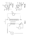
- the figure 1 illustrates the part of the device that triggers an arc.
- the ignition is obtained by inductive switching producing an overvoltage.
- the switched inductance is the primary coil of a transformer 1, the overvoltage being produced at the output of the secondary coil of the transformer, the transformer for amplifying the overvoltage produced on the primary coil.
- the device comprises in particular a step-up transformer 1 composed of a primary winding 11 and at least one secondary winding 12, a primary voltage generator 2, a switch 3 and a control system 4 of this switch.
- the primary winding 11 is on the one hand connected to one terminal of the voltage generator 2 and is connected to the other terminal to the switch 3.
- this primary winding is connected to the terminals of the generator 2 via the switch 3, the voltage across this winding being equal to the voltage of the generator when the switch is in the closed state.
- the switch 3 is for example a MOS type transistor.
- the priming principle of the secondary electric arc of the transformer 1 is based on the initialization of an overvoltage.
- the primary coil 11 of the transformer is charged by the current supplied by the primary voltage generator 2.
- the transistor 3 progressively leads the current flowing in the primary coil 11 until reaching its maximum acceptable current value. Then the transistor acting as a switch, quickly cuts the circuit passing the current from the maximum value to a current of zero value.
- V p Lp dl p / dt
- Lp the inductance the primary coil
- dl p the variation of current in this coil, between the maximum value and the null value and dt being the duration of switching from one value to another.
- This high voltage is all the more important that the inductance Lp is large and the switching time dt is low.
- the transformer is an elevator as in the example of the figure 1
- the high voltage produced across the primary coil is found amplified at the terminals of the secondary coil.
- the transformation ratio between the secondary winding and the primary winding is for example of the order of 100.
- the transistor 3 placed at the primary of the transformer is for example sized to conduct a current of up to 20 A, the primary generator 2 delivering for example a nominal continuous voltage of 65 V and a nominal current of 50 A.
- the secondary circuit of the transformer 1 is represented in a simplified manner. Only the electrodes in the presence 5, 6 likely to cause an electric arc are shown.
- the various embodiments of the secondary circuit of a device according to the invention are represented in particular by the figure 4 and the Figures 5a and 5b .
- An arc 10 appears between the electrodes 5, 6 when the breakdown voltage of the ambient dielectric between these electrodes is reached.
- This voltage is of the order of 30 kV / cm in the air.
- the breakdown voltage depends mainly on the distance separating the two electrodes 5, 6 and the rigidity of the dielectric.
- atmospheric conditions such as temperature, pressure or hygrometry are also influencing factors. It is the same for the geometry and the constituent material of the electrodes.
- the Figures 2a and 2b illustrate two possible control modes of the transistor 3 switching the current in the primary coil 11.
- the control is applied by the control system 4 whose realization is known to those skilled in the art.
- the Figures 2a and 2b illustrate the modes of control by the voltage applied between the gate and the source of the transistor 3 as a function of time.
- the transistor is controlled by a gate-source voltage V gs square-shaped 21.
- the transistor acts as a switch.
- the current I p in the primary coil 11 increases linearly up to the maximum value and then drops sharply to zero, thus moving along a ramp 22.
- the voltage across the primary coil v p is rapidly stabilized at the voltage value V p produced across the generator. Then the switching causes a reverse surge spike 24, always at the terminals of the primary coil 11.
- the overall energy expended is decreased.
- the gate-source control voltage V gs is no longer square but in the form of a ramp 25.
- the current in the primary coil starts circulating later to grow 26 up to the maximum value.
- the voltage across the primary winding remains low 27 while charging the coil.
- the reverse voltage peak 28 depending on the maximum current value reached is the same as that obtained in the first mode.
- the overall electrical energy expended is significantly smaller than in the first mode as indicated by the comparison of the products of the voltage and current Figures 2a and 2b .
- the figure 3 illustrates three possible cases of overvoltages at the terminals of the secondary coil 12, the curves representing the shape of the voltage Vs across the secondary coil as a function of time.
- the secondary coil is for example wired so as to be inverted with respect to the primary voltage.
- a first curve 31 corresponds to a case without arc production.
- a second curve 32 presents a case with an arc.
- an overvoltage is produced when the breakdown voltage is reached then the voltage drops and stabilizes at a given value 321 during the duration of the electric arc ( ⁇ tcc), this stabilized voltage characterizing the intensity of the electric arc.
- ⁇ tcc duration of the electric arc
- the intensity and duration of the arc is not controllable, that is to say in particular that it can not be calibrated in intensity and in duration, and this in a repetitive way.
- the figure 4 shows an exemplary embodiment of a device according to the invention.
- the primary part of the device whose particular function is to initiate the electric arc, is the same as that presented by the figure 1 .
- a generator 2 supplies a voltage V G to the primary coil which charges with a current I p controlled by the switch 3, a MOS type transistor in this example.
- the interruption of the primary current I p causes an overvoltage across the coil secondary 12 initiating an arc as represented by the curves 32, 33 of the figure 3 .
- the secondary coil 12 is connected in series with a load 42 itself in series with the electrodes 5, 6 at the terminals of which an electric arc is likely to reproduce.
- the electrodes 5, 6 symbolize an electrical fault likely to occur, for example a cable break or a loss of contact, these defects being produced in test phase.
- the load 42 in series represents a case of application where the fault occurs in series on an electric charge itself in series with the generator, this is the case in particular of a defect by loss of contact, for example at the a connector.
- Arc initiation is followed by a voltage drop that stabilizes at a given value as shown in curves 32 and 33 of the figure 3 .
- a source of electrical energy for example current, is placed in series with the secondary coil 12 and the location of the circuit where the electric arc occurs, that is to say the electrodes 5 , 6 on the figure 4 .
- the current source is formed from a voltage generator 41, the voltage being for example continuous.
- the current is defined by the voltage across the generator and the electrical loads connected in series with the generator.
- this generator 41 makes it possible to maintain a current in the electric arc and thus to maintain the latter.
- By playing on the intensity of the current and its duration we can calibrate the intensity and duration of the arc and give it also a repetitive character.
- the example of figure 4 represents a case of electric arc in an electrical system powered by a DC voltage, the arc occurring in series with the electric charge.
- Other types of generators can be used as shown by Figures 5a and 5b .
- the wiring of the figure 5a allows to test the first two cases, the generator 41 being either DC voltage or alternating voltage and the load 42 being in series with the electric arc which occurs at the electrodes 5, 6.
- the wiring of the figure 5b allows to test the last two cases, the generator 41 is either DC voltage or alternating voltage and the load 52 being in parallel with the electric arc.
- An operating principle of a device according to the invention is therefore the following.
- the primary part of the transformer 1 initiates the electric arc and the secondary part maintains a controlled electric arc.
- the primary generator 2 provides a charging current to the primary coil 11, this charging current being cut by the switch 3.
- An overvoltage then occurs across the coil 12 of the transformer.
- the winding of the secondary coil is calculated to amplify the primary voltage to achieve in particular the desired breakdown voltage.
- the generator 41 takes the relay to maintain the arc.
- the value of the voltage and its duration make it possible to control the arc with the intensity and the desired duration.
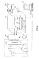
- the figure 6 illustrates an exemplary embodiment of an electric arc generator according to the invention for setting the environmental conditions of the electric arc.
- the electric charge 42 is in series with the electrodes 5, 6 at the terminals of which the electric arc occurs.
- a DC or AC voltage generator 41 is connected in series with the load and the electrodes 5, 6, as in the example of FIG. figure 5a .
- the electrodes 5, 6 are placed in a tank 61 within which it is possible to set environmental conditions. In this example, it is possible to reproduce temperature conditions and pressure conditions. It would be possible to consider also reproducing hygrometric conditions for example.
- a heating and cooling device 62 placed inside the tank 61 makes it possible to set a given temperature inside this tank.
- the latter is also connected by a pipe 66 to a vacuum pump 63 for fixing a given pressure inside, a barometer 64 used to check the internal pressure.
- the temperature range is for example between -10 ° and 50 ° Celsius while the pressure range is for example between 0.2 bar and 1 bar, other ranges can of course be applied.
- the device of the figure 6 allows to set the distance between the electrodes 5, 6.
- the electrodes 5, 6 are mounted on a system 65 which controls their displacement, for example a worm system which causes the displacement of a plate. The displacement is then controlled by the rotation of the screw, itself controlled by a suitable device.
- This system 65 makes it possible to bring the electrodes 5 and 6 closer to each other or away from each other.
- the setting of the arc installation time is, for example, set automatically via the control circuit 4 ensuring the opening or the closing of the switch 3 to the primary of the transformer 1.
- the switch 3 When the switch 3 is in the closed position, the secondary of the transformer operates as a surge generator and initiates an electric arc between the electrodes 5, 6.
- the switch 3 When the switch 3 is open, the generator at the secondary level no longer supplies the load, the relay being taken by the voltage generator 41 which by the same maintains the electric arc.
- the intensity of the current in the secondary circuit, and therefore in the electric arc depends on the value of the load 42 mounted in series. The adjustment of the current can therefore be done by playing on this load value.
- the complex part of the load, inductive and capacitive component can also be controlled.
- the various parameters of the circuit are for example controllable from a computer 60 connected to the adapted interface means, to the control members of the load 42, the switch 3, the heating and cooling system 62 and the pump 63.
- control programs can thus be implemented automatically by the computer 60.
- a device makes it possible to produce, in a controlled manner, intensity and duration of arcs in series and in parallel, in continuous or alternating mode.
- the arc fault can be systematically created at each overvoltage and the secondary generator 41 provides the power to maintain the electric arc, in series or in parallel with a load.
- Different types of loads, among which particular circuit breakers, can be used to observe the behavior of the arc fault in a complex circuit.
- the invention advantageously makes it possible to test all types of devices and arc disjunction systems.
Landscapes
- Physics & Mathematics (AREA)
- General Physics & Mathematics (AREA)
- Engineering & Computer Science (AREA)
- General Engineering & Computer Science (AREA)
- Chemical & Material Sciences (AREA)
- Combustion & Propulsion (AREA)
- Generation Of Surge Voltage And Current (AREA)
Claims (14)
- Vorrichtung zum gesteuerten Erzeugen eines Lichtbogens, dadurch gekennzeichnet, dass sie wenigstens Folgendes umfasst:- ein System zum Zünden eines Lichtbogens (3, 4, 11, 12) an den Anschlüssen von zwei Elektroden (5, 6) durch induktive Schaltung, das an seinem Ausgang (A, B) eine Überspannung zu den Anschlüssen dieser Elektroden (5, 6) produziert;- eine elektrische Energiequelle (41, 42, 52), die in Serie mit dem Ausgang (A, B) des Zündsystems geschaltet ist, wobei die Quelle den Lichtbogen mit Strom versorgt.
- Vorrichtung nach Anspruch 1, dadurch gekennzeichnet, dass die elektrische Energiequelle ein Spannungsgenerator (41) ist, wobei eine elektrische Ladung (42, 52) den Wert des Stroms definiert.
- Vorrichtung nach Anspruch 1, dadurch gekennzeichnet, dass die elektrische Energiequelle ein Stromgenerator ist, wobei eine elektrische Ladung (41) den Wert des Stroms definiert.
- Vorrichtung nach einem der vorherigen Ansprüche, dadurch gekennzeichnet, dass das Zündsystem wenigstens einen Transformator (1), einen Primärspannungsgenerator (2) und einen Schalter (3) umfasst, die in Serie mit der Primärwicklung (11) des Transformators (1) geschaltet sind, wobei die Überspannung zu den Anschlüssen der Elektroden (5, 6) an den Anschlüssen (A, B) der Sekundärwicklung (12) des Transformators erzeugt wird, wenn der Schalter (3) in einer geschlossenen Position ist.
- Vorrichtung nach Anspruch 4, dadurch gekennzeichnet, dass die Schließdauer des Schalters (3) regelbar ist (4).
- Vorrichtung nach einem der vorherigen Ansprüche, dadurch gekennzeichnet, dass die elektrische Ladung (42) in Serie mit der elektrischen Energiequelle (41) geschaltet ist.
- Vorrichtung nach einem der Ansprüche 1 bis 5, dadurch gekennzeichnet, dass die elektrische Ladung (52) parallel mit der elektrischen Energiequelle (41) geschaltet ist.
- Vorrichtung nach Anspruch 6 oder 7, dadurch gekennzeichnet, dass der Wert der elektrischen Ladung (42, 52) regelbar ist.
- Vorrichtung nach einem der Ansprüche 2 bis 8, dadurch gekennzeichnet, dass die Spannung am Ausgang des Spannungsgenerators (41) Gleichspannung ist.
- Vorrichtung nach einem der Ansprüche 2 bis 8, dadurch gekennzeichnet, dass die Spannung am Ausgang des Spannungsgenerators (41) Wechselspannung ist.
- Vorrichtung nach einem der vorherigen Ansprüche, dadurch gekennzeichnet, dass die Elektroden (5, 6) in einem Behälter (61) platziert sind, in dem Umweltbedingungen simuliert werden.
- Vorrichtung nach Anspruch 11, dadurch gekennzeichnet, dass der Behälter (61) ein steuerbares Heiz- und Kühlsystem (62) umfasst.
- Vorrichtung nach Anspruch 11 oder 12, dadurch gekennzeichnet, dass sie eine steuerbare Vakuumpumpe (63) umfasst, die mit dem Behälter (61) zum Regeln des Drucks im Innern des Behälters verbunden ist.
- Vorrichtung nach einem der vorherigen Ansprüche, dadurch gekennzeichnet, dass sie ein System (65) zum Vergößern oder Verkleinern des Abstands der Elektroden (5, 6) voneinander umfasst, wobei das System steuerbar ist.
Applications Claiming Priority (2)
| Application Number | Priority Date | Filing Date | Title |
|---|---|---|---|
| FR1055074A FR2961968B1 (fr) | 2010-06-25 | 2010-06-25 | Dispositif de generation controlee d'arcs electriques |
| PCT/EP2011/060525 WO2011161200A1 (fr) | 2010-06-25 | 2011-06-22 | Dispositif de generation contrôlee d'arcs electriques |
Publications (2)
| Publication Number | Publication Date |
|---|---|
| EP2585840A1 EP2585840A1 (de) | 2013-05-01 |
| EP2585840B1 true EP2585840B1 (de) | 2015-01-21 |
Family
ID=43607962
Family Applications (1)
| Application Number | Title | Priority Date | Filing Date |
|---|---|---|---|
| EP11730608.4A Not-in-force EP2585840B1 (de) | 2010-06-25 | 2011-06-22 | Vorrichtung für die gesteuerte erzeugung von lichtbögen |
Country Status (5)
| Country | Link |
|---|---|
| US (1) | US20130207545A1 (de) |
| EP (1) | EP2585840B1 (de) |
| CN (1) | CN103069288B (de) |
| FR (1) | FR2961968B1 (de) |
| WO (1) | WO2011161200A1 (de) |
Families Citing this family (7)
| Publication number | Priority date | Publication date | Assignee | Title |
|---|---|---|---|---|
| DE102014202533A1 (de) * | 2014-02-12 | 2015-08-13 | Siemens Aktiengesellschaft | Testgerät und Testverfahren für einen Brandschutzschalter |
| US9828967B2 (en) * | 2015-06-05 | 2017-11-28 | Ming Zheng | System and method for elastic breakdown ignition via multipole high frequency discharge |
| US10261120B1 (en) * | 2016-05-27 | 2019-04-16 | National Technology & Engineering Solutions Of Sandia, Llc | Arc plasma-generating systems and methods thereof |
| CN109212284B (zh) * | 2018-11-21 | 2020-12-08 | 华侨大学 | 一种可精确控制的电弧故障发生系统的控制方法 |
| CN114200290B (zh) * | 2021-10-29 | 2025-10-03 | 国网安徽省电力有限公司宣城供电公司 | 真空断路器灭弧能力检测装置 |
| CN114236203B (zh) * | 2021-11-29 | 2023-10-24 | 国网北京市电力公司 | 负载控制系统、方法、存储介质以及电子装置 |
| FR3156917A1 (fr) * | 2023-12-15 | 2025-06-20 | Safran Electrical & Power | Dispositif et procédé d’amorçage d’un arc électrique sur un équipement électronique notamment de puissance. |
Family Cites Families (11)
| Publication number | Priority date | Publication date | Assignee | Title |
|---|---|---|---|---|
| DE2048960A1 (de) * | 1970-10-06 | 1972-04-13 | Bosch Gmbh Robert | Kondensatorzündanlage für Brennkraftmaschinen |
| US3714507A (en) * | 1971-03-02 | 1973-01-30 | Delta Prod Inc | Controlled variable spark capacitor discharge ignition system |
| FR2704710B1 (fr) * | 1993-04-30 | 1995-06-23 | Cegelec Metals Systems | Dispositif convertisseur de puissance perfectionné pour l'alimentation en courant continu d'un four électrique à arc. |
| JP2925467B2 (ja) * | 1994-12-27 | 1999-07-28 | 株式会社三社電機製作所 | プラズマアーク電源装置 |
| US5590012A (en) * | 1995-03-30 | 1996-12-31 | Siemens Energy & Automation, Inc. | Electric arc detector sensor circuit |
| US6876204B2 (en) * | 2003-04-25 | 2005-04-05 | Ideal Industries, Inc. | Test instrument for arc fault circuit interrupters |
| JP4108108B2 (ja) * | 2004-03-29 | 2008-06-25 | 三菱電機株式会社 | プラズマ発生用電源装置 |
| JP4760053B2 (ja) * | 2005-02-28 | 2011-08-31 | パナソニック株式会社 | アーク溶接装置の制御方法およびアーク溶接装置 |
| KR100909226B1 (ko) * | 2007-05-14 | 2009-07-23 | 주식회사 헤코 | 아크결함차단기 테스트용 아크 파형 발생장치 |
| WO2009031180A1 (ja) * | 2007-09-04 | 2009-03-12 | Shimadzu Corporation | 発光分析装置 |
| JP5124349B2 (ja) * | 2008-06-02 | 2013-01-23 | 株式会社ダイヘン | 電源装置及びアーク加工用電源装置 |
-
2010
- 2010-06-25 FR FR1055074A patent/FR2961968B1/fr active Active
-
2011
- 2011-06-22 EP EP11730608.4A patent/EP2585840B1/de not_active Not-in-force
- 2011-06-22 CN CN201180039667.7A patent/CN103069288B/zh not_active Expired - Fee Related
- 2011-06-22 US US13/806,698 patent/US20130207545A1/en not_active Abandoned
- 2011-06-22 WO PCT/EP2011/060525 patent/WO2011161200A1/fr not_active Ceased
Also Published As
| Publication number | Publication date |
|---|---|
| FR2961968B1 (fr) | 2012-08-10 |
| EP2585840A1 (de) | 2013-05-01 |
| CN103069288A (zh) | 2013-04-24 |
| US20130207545A1 (en) | 2013-08-15 |
| CN103069288B (zh) | 2016-02-10 |
| WO2011161200A1 (fr) | 2011-12-29 |
| FR2961968A1 (fr) | 2011-12-30 |
Similar Documents
| Publication | Publication Date | Title |
|---|---|---|
| WO2011161200A1 (fr) | Dispositif de generation contrôlee d'arcs electriques | |
| FR2864172A1 (fr) | Circuit de detection d'ionisation a double etage | |
| EP2978005A1 (de) | Stromunterbrechungsvorrichtung auf einer Übertragungsleitung | |
| US10510278B2 (en) | Signal loading method and signal generator | |
| FR3055495A1 (fr) | Procede et dispositif de circuit pour couper une source de tension d'au moins un consommateur | |
| FR2873509A1 (fr) | Dispositif de protection contre les surtensions a capacite de coupure du courant de fuite ameliore | |
| EP0271396A1 (de) | Verfahren und Vorrichtung zur Zündung von Entladungslampen | |
| EP3051101B1 (de) | Hochenergie-zündunganlage, insbesondere für gasturbine | |
| FR2648001A1 (fr) | Alimentation en courant continu d'electrodes a plasma et procede pour regenerer un plasma | |
| WO2018220307A1 (fr) | Systeme d'hybridation pour courant continu haute tension | |
| FR3021167B1 (fr) | Circuit de derivation d'energie et procede de mise en fonctionnement de ce circuit | |
| EP3413419B1 (de) | Elektrische schaltung mit elektrischer schutzeinrichtung - integritätstest | |
| EP3291271B1 (de) | Steuerungsverfahren einer betätigungsvorrichtung und entsprechende betätigungsvorrichtung und schaltvorrichtung | |
| EP2577024A1 (de) | Zündkerzenvorwärmung | |
| FR2896335A1 (fr) | Disjoncteur de generateur avec resistance inseree | |
| EP3651170A1 (de) | Erfassungs- und begrenzungssystem von effekten von isolationsverlusten eines elektrischen transformators | |
| FR2889775A1 (fr) | Procede et montage de limitation de la dissipation d'un commutateur de puissance a semi-conducteur. | |
| CA2815615A1 (fr) | Circuit d'alimentation pour un aeronef incluant une machine asynchrone | |
| FR2976083A1 (fr) | Dispositif de detection d'un defaut d'isolement | |
| CA3029365C (fr) | Dispositif d'amplification de puissance | |
| EP1560474A2 (de) | Schutzschaltung für ein Schaltnetzteil und Beleuchtungseinrichtung für ein Fahrzeug | |
| FR2717534A1 (fr) | Générateur d'allumage haute énergie notamment pour turbine à gaz. | |
| EP3654045B1 (de) | Detektions- und übertragungsverfahren von information über einen schlafenden fehler | |
| WO2025074055A1 (fr) | Dispositif et procede de protection d'une installation electrique | |
| FR3066056A1 (fr) | Dispositif limitant l'apparition de decharges partielles sur un equipement de generation d'une tension electrique, et procede associe. |
Legal Events
| Date | Code | Title | Description |
|---|---|---|---|
| PUAI | Public reference made under article 153(3) epc to a published international application that has entered the european phase |
Free format text: ORIGINAL CODE: 0009012 |
|
| 17P | Request for examination filed |
Effective date: 20121219 |
|
| AK | Designated contracting states |
Kind code of ref document: A1 Designated state(s): AL AT BE BG CH CY CZ DE DK EE ES FI FR GB GR HR HU IE IS IT LI LT LU LV MC MK MT NL NO PL PT RO RS SE SI SK SM TR |
|
| DAX | Request for extension of the european patent (deleted) | ||
| REG | Reference to a national code |
Ref country code: DE Ref legal event code: R079 Ref document number: 602011013338 Country of ref document: DE Free format text: PREVIOUS MAIN CLASS: G01R0031140000 Ipc: G01R0031280000 |
|
| RIC1 | Information provided on ipc code assigned before grant |
Ipc: H01T 15/00 20060101ALI20140709BHEP Ipc: G01R 31/14 20060101ALI20140709BHEP Ipc: G01R 31/28 20060101AFI20140709BHEP |
|
| GRAP | Despatch of communication of intention to grant a patent |
Free format text: ORIGINAL CODE: EPIDOSNIGR1 |
|
| INTG | Intention to grant announced |
Effective date: 20141002 |
|
| GRAS | Grant fee paid |
Free format text: ORIGINAL CODE: EPIDOSNIGR3 |
|
| GRAA | (expected) grant |
Free format text: ORIGINAL CODE: 0009210 |
|
| AK | Designated contracting states |
Kind code of ref document: B1 Designated state(s): AL AT BE BG CH CY CZ DE DK EE ES FI FR GB GR HR HU IE IS IT LI LT LU LV MC MK MT NL NO PL PT RO RS SE SI SK SM TR |
|
| REG | Reference to a national code |
Ref country code: GB Ref legal event code: FG4D Free format text: NOT ENGLISH |
|
| REG | Reference to a national code |
Ref country code: CH Ref legal event code: EP |
|
| REG | Reference to a national code |
Ref country code: IE Ref legal event code: FG4D Free format text: LANGUAGE OF EP DOCUMENT: FRENCH |
|
| REG | Reference to a national code |
Ref country code: DE Ref legal event code: R096 Ref document number: 602011013338 Country of ref document: DE Effective date: 20150305 |
|
| REG | Reference to a national code |
Ref country code: AT Ref legal event code: REF Ref document number: 709415 Country of ref document: AT Kind code of ref document: T Effective date: 20150315 |
|
| REG | Reference to a national code |
Ref country code: CH Ref legal event code: NV Representative=s name: MARKS AND CLERK (LUXEMBOURG) LLP, CH |
|
| REG | Reference to a national code |
Ref country code: NL Ref legal event code: VDEP Effective date: 20150121 |
|
| REG | Reference to a national code |
Ref country code: AT Ref legal event code: MK05 Ref document number: 709415 Country of ref document: AT Kind code of ref document: T Effective date: 20150121 |
|
| REG | Reference to a national code |
Ref country code: LT Ref legal event code: MG4D |
|
| PG25 | Lapsed in a contracting state [announced via postgrant information from national office to epo] |
Ref country code: ES Free format text: LAPSE BECAUSE OF FAILURE TO SUBMIT A TRANSLATION OF THE DESCRIPTION OR TO PAY THE FEE WITHIN THE PRESCRIBED TIME-LIMIT Effective date: 20150121 Ref country code: SE Free format text: LAPSE BECAUSE OF FAILURE TO SUBMIT A TRANSLATION OF THE DESCRIPTION OR TO PAY THE FEE WITHIN THE PRESCRIBED TIME-LIMIT Effective date: 20150121 Ref country code: FI Free format text: LAPSE BECAUSE OF FAILURE TO SUBMIT A TRANSLATION OF THE DESCRIPTION OR TO PAY THE FEE WITHIN THE PRESCRIBED TIME-LIMIT Effective date: 20150121 Ref country code: NO Free format text: LAPSE BECAUSE OF FAILURE TO SUBMIT A TRANSLATION OF THE DESCRIPTION OR TO PAY THE FEE WITHIN THE PRESCRIBED TIME-LIMIT Effective date: 20150421 Ref country code: LT Free format text: LAPSE BECAUSE OF FAILURE TO SUBMIT A TRANSLATION OF THE DESCRIPTION OR TO PAY THE FEE WITHIN THE PRESCRIBED TIME-LIMIT Effective date: 20150121 Ref country code: HR Free format text: LAPSE BECAUSE OF FAILURE TO SUBMIT A TRANSLATION OF THE DESCRIPTION OR TO PAY THE FEE WITHIN THE PRESCRIBED TIME-LIMIT Effective date: 20150121 Ref country code: BG Free format text: LAPSE BECAUSE OF FAILURE TO SUBMIT A TRANSLATION OF THE DESCRIPTION OR TO PAY THE FEE WITHIN THE PRESCRIBED TIME-LIMIT Effective date: 20150421 |
|
| PG25 | Lapsed in a contracting state [announced via postgrant information from national office to epo] |
Ref country code: GR Free format text: LAPSE BECAUSE OF FAILURE TO SUBMIT A TRANSLATION OF THE DESCRIPTION OR TO PAY THE FEE WITHIN THE PRESCRIBED TIME-LIMIT Effective date: 20150422 Ref country code: PL Free format text: LAPSE BECAUSE OF FAILURE TO SUBMIT A TRANSLATION OF THE DESCRIPTION OR TO PAY THE FEE WITHIN THE PRESCRIBED TIME-LIMIT Effective date: 20150121 Ref country code: LV Free format text: LAPSE BECAUSE OF FAILURE TO SUBMIT A TRANSLATION OF THE DESCRIPTION OR TO PAY THE FEE WITHIN THE PRESCRIBED TIME-LIMIT Effective date: 20150121 Ref country code: AT Free format text: LAPSE BECAUSE OF FAILURE TO SUBMIT A TRANSLATION OF THE DESCRIPTION OR TO PAY THE FEE WITHIN THE PRESCRIBED TIME-LIMIT Effective date: 20150121 Ref country code: RS Free format text: LAPSE BECAUSE OF FAILURE TO SUBMIT A TRANSLATION OF THE DESCRIPTION OR TO PAY THE FEE WITHIN THE PRESCRIBED TIME-LIMIT Effective date: 20150121 Ref country code: IS Free format text: LAPSE BECAUSE OF FAILURE TO SUBMIT A TRANSLATION OF THE DESCRIPTION OR TO PAY THE FEE WITHIN THE PRESCRIBED TIME-LIMIT Effective date: 20150521 Ref country code: NL Free format text: LAPSE BECAUSE OF FAILURE TO SUBMIT A TRANSLATION OF THE DESCRIPTION OR TO PAY THE FEE WITHIN THE PRESCRIBED TIME-LIMIT Effective date: 20150121 |
|
| REG | Reference to a national code |
Ref country code: DE Ref legal event code: R097 Ref document number: 602011013338 Country of ref document: DE |
|
| PG25 | Lapsed in a contracting state [announced via postgrant information from national office to epo] |
Ref country code: SK Free format text: LAPSE BECAUSE OF FAILURE TO SUBMIT A TRANSLATION OF THE DESCRIPTION OR TO PAY THE FEE WITHIN THE PRESCRIBED TIME-LIMIT Effective date: 20150121 Ref country code: CZ Free format text: LAPSE BECAUSE OF FAILURE TO SUBMIT A TRANSLATION OF THE DESCRIPTION OR TO PAY THE FEE WITHIN THE PRESCRIBED TIME-LIMIT Effective date: 20150121 Ref country code: DK Free format text: LAPSE BECAUSE OF FAILURE TO SUBMIT A TRANSLATION OF THE DESCRIPTION OR TO PAY THE FEE WITHIN THE PRESCRIBED TIME-LIMIT Effective date: 20150121 Ref country code: EE Free format text: LAPSE BECAUSE OF FAILURE TO SUBMIT A TRANSLATION OF THE DESCRIPTION OR TO PAY THE FEE WITHIN THE PRESCRIBED TIME-LIMIT Effective date: 20150121 Ref country code: RO Free format text: LAPSE BECAUSE OF FAILURE TO SUBMIT A TRANSLATION OF THE DESCRIPTION OR TO PAY THE FEE WITHIN THE PRESCRIBED TIME-LIMIT Effective date: 20150121 |
|
| PLBE | No opposition filed within time limit |
Free format text: ORIGINAL CODE: 0009261 |
|
| STAA | Information on the status of an ep patent application or granted ep patent |
Free format text: STATUS: NO OPPOSITION FILED WITHIN TIME LIMIT |
|
| 26N | No opposition filed |
Effective date: 20151022 |
|
| PG25 | Lapsed in a contracting state [announced via postgrant information from national office to epo] |
Ref country code: IT Free format text: LAPSE BECAUSE OF FAILURE TO SUBMIT A TRANSLATION OF THE DESCRIPTION OR TO PAY THE FEE WITHIN THE PRESCRIBED TIME-LIMIT Effective date: 20150121 |
|
| PG25 | Lapsed in a contracting state [announced via postgrant information from national office to epo] |
Ref country code: MC Free format text: LAPSE BECAUSE OF FAILURE TO SUBMIT A TRANSLATION OF THE DESCRIPTION OR TO PAY THE FEE WITHIN THE PRESCRIBED TIME-LIMIT Effective date: 20150121 |
|
| PG25 | Lapsed in a contracting state [announced via postgrant information from national office to epo] |
Ref country code: SI Free format text: LAPSE BECAUSE OF FAILURE TO SUBMIT A TRANSLATION OF THE DESCRIPTION OR TO PAY THE FEE WITHIN THE PRESCRIBED TIME-LIMIT Effective date: 20150121 Ref country code: LU Free format text: LAPSE BECAUSE OF FAILURE TO SUBMIT A TRANSLATION OF THE DESCRIPTION OR TO PAY THE FEE WITHIN THE PRESCRIBED TIME-LIMIT Effective date: 20150622 |
|
| REG | Reference to a national code |
Ref country code: IE Ref legal event code: MM4A |
|
| PG25 | Lapsed in a contracting state [announced via postgrant information from national office to epo] |
Ref country code: IE Free format text: LAPSE BECAUSE OF NON-PAYMENT OF DUE FEES Effective date: 20150622 |
|
| REG | Reference to a national code |
Ref country code: FR Ref legal event code: PLFP Year of fee payment: 6 |
|
| PG25 | Lapsed in a contracting state [announced via postgrant information from national office to epo] |
Ref country code: MT Free format text: LAPSE BECAUSE OF FAILURE TO SUBMIT A TRANSLATION OF THE DESCRIPTION OR TO PAY THE FEE WITHIN THE PRESCRIBED TIME-LIMIT Effective date: 20150121 |
|
| PG25 | Lapsed in a contracting state [announced via postgrant information from national office to epo] |
Ref country code: HU Free format text: LAPSE BECAUSE OF FAILURE TO SUBMIT A TRANSLATION OF THE DESCRIPTION OR TO PAY THE FEE WITHIN THE PRESCRIBED TIME-LIMIT; INVALID AB INITIO Effective date: 20110622 Ref country code: SM Free format text: LAPSE BECAUSE OF FAILURE TO SUBMIT A TRANSLATION OF THE DESCRIPTION OR TO PAY THE FEE WITHIN THE PRESCRIBED TIME-LIMIT Effective date: 20150121 |
|
| REG | Reference to a national code |
Ref country code: FR Ref legal event code: PLFP Year of fee payment: 7 |
|
| PG25 | Lapsed in a contracting state [announced via postgrant information from national office to epo] |
Ref country code: CY Free format text: LAPSE BECAUSE OF FAILURE TO SUBMIT A TRANSLATION OF THE DESCRIPTION OR TO PAY THE FEE WITHIN THE PRESCRIBED TIME-LIMIT Effective date: 20150121 |
|
| PG25 | Lapsed in a contracting state [announced via postgrant information from national office to epo] |
Ref country code: TR Free format text: LAPSE BECAUSE OF FAILURE TO SUBMIT A TRANSLATION OF THE DESCRIPTION OR TO PAY THE FEE WITHIN THE PRESCRIBED TIME-LIMIT Effective date: 20150121 |
|
| REG | Reference to a national code |
Ref country code: FR Ref legal event code: PLFP Year of fee payment: 8 |
|
| PG25 | Lapsed in a contracting state [announced via postgrant information from national office to epo] |
Ref country code: PT Free format text: LAPSE BECAUSE OF FAILURE TO SUBMIT A TRANSLATION OF THE DESCRIPTION OR TO PAY THE FEE WITHIN THE PRESCRIBED TIME-LIMIT Effective date: 20150121 Ref country code: MK Free format text: LAPSE BECAUSE OF FAILURE TO SUBMIT A TRANSLATION OF THE DESCRIPTION OR TO PAY THE FEE WITHIN THE PRESCRIBED TIME-LIMIT Effective date: 20150121 |
|
| PG25 | Lapsed in a contracting state [announced via postgrant information from national office to epo] |
Ref country code: AL Free format text: LAPSE BECAUSE OF FAILURE TO SUBMIT A TRANSLATION OF THE DESCRIPTION OR TO PAY THE FEE WITHIN THE PRESCRIBED TIME-LIMIT Effective date: 20150121 |
|
| PGFP | Annual fee paid to national office [announced via postgrant information from national office to epo] |
Ref country code: BE Payment date: 20190617 Year of fee payment: 9 |
|
| PGFP | Annual fee paid to national office [announced via postgrant information from national office to epo] |
Ref country code: CH Payment date: 20190614 Year of fee payment: 9 |
|
| PGFP | Annual fee paid to national office [announced via postgrant information from national office to epo] |
Ref country code: GB Payment date: 20190611 Year of fee payment: 9 |
|
| REG | Reference to a national code |
Ref country code: CH Ref legal event code: PL |
|
| GBPC | Gb: european patent ceased through non-payment of renewal fee |
Effective date: 20200622 |
|
| REG | Reference to a national code |
Ref country code: BE Ref legal event code: MM Effective date: 20200630 |
|
| PG25 | Lapsed in a contracting state [announced via postgrant information from national office to epo] |
Ref country code: GB Free format text: LAPSE BECAUSE OF NON-PAYMENT OF DUE FEES Effective date: 20200622 Ref country code: CH Free format text: LAPSE BECAUSE OF NON-PAYMENT OF DUE FEES Effective date: 20200630 Ref country code: LI Free format text: LAPSE BECAUSE OF NON-PAYMENT OF DUE FEES Effective date: 20200630 |
|
| PG25 | Lapsed in a contracting state [announced via postgrant information from national office to epo] |
Ref country code: BE Free format text: LAPSE BECAUSE OF NON-PAYMENT OF DUE FEES Effective date: 20200630 |
|
| PGFP | Annual fee paid to national office [announced via postgrant information from national office to epo] |
Ref country code: DE Payment date: 20220621 Year of fee payment: 12 |
|
| PGFP | Annual fee paid to national office [announced via postgrant information from national office to epo] |
Ref country code: FR Payment date: 20220630 Year of fee payment: 12 |
|
| REG | Reference to a national code |
Ref country code: DE Ref legal event code: R119 Ref document number: 602011013338 Country of ref document: DE |
|
| PG25 | Lapsed in a contracting state [announced via postgrant information from national office to epo] |
Ref country code: DE Free format text: LAPSE BECAUSE OF NON-PAYMENT OF DUE FEES Effective date: 20240103 |
|
| PG25 | Lapsed in a contracting state [announced via postgrant information from national office to epo] |
Ref country code: FR Free format text: LAPSE BECAUSE OF NON-PAYMENT OF DUE FEES Effective date: 20230630 |