EP2585742B1 - Schaltvorrichtung für einen fluidstrom - Google Patents
Schaltvorrichtung für einen fluidstrom Download PDFInfo
- Publication number
- EP2585742B1 EP2585742B1 EP11724562.1A EP11724562A EP2585742B1 EP 2585742 B1 EP2585742 B1 EP 2585742B1 EP 11724562 A EP11724562 A EP 11724562A EP 2585742 B1 EP2585742 B1 EP 2585742B1
- Authority
- EP
- European Patent Office
- Prior art keywords
- switching
- pair
- valve
- fluid
- levers
- Prior art date
- Legal status (The legal status is an assumption and is not a legal conclusion. Google has not performed a legal analysis and makes no representation as to the accuracy of the status listed.)
- Not-in-force
Links
- 239000012530 fluid Substances 0.000 title claims description 50
- 238000000034 method Methods 0.000 claims description 18
- 125000006850 spacer group Chemical group 0.000 claims description 8
- 239000000126 substance Substances 0.000 claims description 3
- 238000009826 distribution Methods 0.000 description 37
- 230000008878 coupling Effects 0.000 description 8
- 238000010168 coupling process Methods 0.000 description 8
- 238000005859 coupling reaction Methods 0.000 description 8
- 238000001914 filtration Methods 0.000 description 3
- 238000004519 manufacturing process Methods 0.000 description 3
- 230000002093 peripheral effect Effects 0.000 description 3
- 230000000694 effects Effects 0.000 description 2
- 239000000443 aerosol Substances 0.000 description 1
- 230000015572 biosynthetic process Effects 0.000 description 1
- 230000000903 blocking effect Effects 0.000 description 1
- 239000012459 cleaning agent Substances 0.000 description 1
- 230000000295 complement effect Effects 0.000 description 1
- 150000001875 compounds Chemical class 0.000 description 1
- 239000007788 liquid Substances 0.000 description 1
- 238000012423 maintenance Methods 0.000 description 1
- 238000002360 preparation method Methods 0.000 description 1
- 238000004886 process control Methods 0.000 description 1
Images





Classifications
-
- F—MECHANICAL ENGINEERING; LIGHTING; HEATING; WEAPONS; BLASTING
- F16—ENGINEERING ELEMENTS AND UNITS; GENERAL MEASURES FOR PRODUCING AND MAINTAINING EFFECTIVE FUNCTIONING OF MACHINES OR INSTALLATIONS; THERMAL INSULATION IN GENERAL
- F16K—VALVES; TAPS; COCKS; ACTUATING-FLOATS; DEVICES FOR VENTING OR AERATING
- F16K35/00—Means to prevent accidental or unauthorised actuation
- F16K35/14—Means to prevent accidental or unauthorised actuation interlocking two or more valves
-
- B—PERFORMING OPERATIONS; TRANSPORTING
- B01—PHYSICAL OR CHEMICAL PROCESSES OR APPARATUS IN GENERAL
- B01D—SEPARATION
- B01D35/00—Filtering devices having features not specifically covered by groups B01D24/00 - B01D33/00, or for applications not specifically covered by groups B01D24/00 - B01D33/00; Auxiliary devices for filtration; Filter housing constructions
- B01D35/12—Devices for taking out of action one or more units of multi- unit filters, e.g. for regeneration
-
- B—PERFORMING OPERATIONS; TRANSPORTING
- B01—PHYSICAL OR CHEMICAL PROCESSES OR APPARATUS IN GENERAL
- B01D—SEPARATION
- B01D35/00—Filtering devices having features not specifically covered by groups B01D24/00 - B01D33/00, or for applications not specifically covered by groups B01D24/00 - B01D33/00; Auxiliary devices for filtration; Filter housing constructions
- B01D35/30—Filter housing constructions
-
- F—MECHANICAL ENGINEERING; LIGHTING; HEATING; WEAPONS; BLASTING
- F16—ENGINEERING ELEMENTS AND UNITS; GENERAL MEASURES FOR PRODUCING AND MAINTAINING EFFECTIVE FUNCTIONING OF MACHINES OR INSTALLATIONS; THERMAL INSULATION IN GENERAL
- F16K—VALVES; TAPS; COCKS; ACTUATING-FLOATS; DEVICES FOR VENTING OR AERATING
- F16K11/00—Multiple-way valves, e.g. mixing valves; Pipe fittings incorporating such valves
- F16K11/10—Multiple-way valves, e.g. mixing valves; Pipe fittings incorporating such valves with two or more closure members not moving as a unit
- F16K11/20—Multiple-way valves, e.g. mixing valves; Pipe fittings incorporating such valves with two or more closure members not moving as a unit operated by separate actuating members
-
- F—MECHANICAL ENGINEERING; LIGHTING; HEATING; WEAPONS; BLASTING
- F16—ENGINEERING ELEMENTS AND UNITS; GENERAL MEASURES FOR PRODUCING AND MAINTAINING EFFECTIVE FUNCTIONING OF MACHINES OR INSTALLATIONS; THERMAL INSULATION IN GENERAL
- F16K—VALVES; TAPS; COCKS; ACTUATING-FLOATS; DEVICES FOR VENTING OR AERATING
- F16K11/00—Multiple-way valves, e.g. mixing valves; Pipe fittings incorporating such valves
- F16K11/10—Multiple-way valves, e.g. mixing valves; Pipe fittings incorporating such valves with two or more closure members not moving as a unit
- F16K11/20—Multiple-way valves, e.g. mixing valves; Pipe fittings incorporating such valves with two or more closure members not moving as a unit operated by separate actuating members
- F16K11/22—Multiple-way valves, e.g. mixing valves; Pipe fittings incorporating such valves with two or more closure members not moving as a unit operated by separate actuating members with an actuating member for each valve, e.g. interconnected to form multiple-way valves
-
- F—MECHANICAL ENGINEERING; LIGHTING; HEATING; WEAPONS; BLASTING
- F16—ENGINEERING ELEMENTS AND UNITS; GENERAL MEASURES FOR PRODUCING AND MAINTAINING EFFECTIVE FUNCTIONING OF MACHINES OR INSTALLATIONS; THERMAL INSULATION IN GENERAL
- F16K—VALVES; TAPS; COCKS; ACTUATING-FLOATS; DEVICES FOR VENTING OR AERATING
- F16K31/00—Actuating devices; Operating means; Releasing devices
- F16K31/44—Mechanical actuating means
-
- Y—GENERAL TAGGING OF NEW TECHNOLOGICAL DEVELOPMENTS; GENERAL TAGGING OF CROSS-SECTIONAL TECHNOLOGIES SPANNING OVER SEVERAL SECTIONS OF THE IPC; TECHNICAL SUBJECTS COVERED BY FORMER USPC CROSS-REFERENCE ART COLLECTIONS [XRACs] AND DIGESTS
- Y10—TECHNICAL SUBJECTS COVERED BY FORMER USPC
- Y10T—TECHNICAL SUBJECTS COVERED BY FORMER US CLASSIFICATION
- Y10T137/00—Fluid handling
- Y10T137/8593—Systems
- Y10T137/87096—Valves with separate, correlated, actuators
-
- Y—GENERAL TAGGING OF NEW TECHNOLOGICAL DEVELOPMENTS; GENERAL TAGGING OF CROSS-SECTIONAL TECHNOLOGIES SPANNING OVER SEVERAL SECTIONS OF THE IPC; TECHNICAL SUBJECTS COVERED BY FORMER USPC CROSS-REFERENCE ART COLLECTIONS [XRACs] AND DIGESTS
- Y10—TECHNICAL SUBJECTS COVERED BY FORMER USPC
- Y10T—TECHNICAL SUBJECTS COVERED BY FORMER US CLASSIFICATION
- Y10T137/00—Fluid handling
- Y10T137/8593—Systems
- Y10T137/87096—Valves with separate, correlated, actuators
- Y10T137/87113—Interlocked
-
- Y—GENERAL TAGGING OF NEW TECHNOLOGICAL DEVELOPMENTS; GENERAL TAGGING OF CROSS-SECTIONAL TECHNOLOGIES SPANNING OVER SEVERAL SECTIONS OF THE IPC; TECHNICAL SUBJECTS COVERED BY FORMER USPC CROSS-REFERENCE ART COLLECTIONS [XRACs] AND DIGESTS
- Y10—TECHNICAL SUBJECTS COVERED BY FORMER USPC
- Y10T—TECHNICAL SUBJECTS COVERED BY FORMER US CLASSIFICATION
- Y10T137/00—Fluid handling
- Y10T137/8593—Systems
- Y10T137/87096—Valves with separate, correlated, actuators
- Y10T137/87121—Coaxial stems
- Y10T137/87129—Rotary
Definitions
- the invention relates to a switching device for a fluid flow, in particular for the passage of a high-pressure fluid from a first treatment device to a second treatment device, wherein in each treatment device, the fluid can be subjected to a chemical and / or physical process step, according to the feature configuration of the preamble of claim 1.
- a generic switching device in which a fluid under high pressure can optionally be passed through a first or a second treatment device in which the fluid undergoes a treatment such as a filtration.
- the two treatment devices can be connected to one another via a first and a second fluid-conducting connection.
- a treated-fluid outlet valve is provided approximately centrally and an inlet valve for fluid to be treated is provided approximately in the middle of the second fluid-carrying connection.
- a safety valve is provided in both fluid-carrying connections, via which the treatment facilities can be supplied with the fluid supplied via the inlet valve and with respect to the other fluid-carrying Compound treated fluid can be supplied from the treatment facilities to the outlet valve.
- the inlet and the outlet valve and the two treatment devices each pairwise associated two safety valves are each connected to each other via a pair of valve coupling shaft.
- a shift lever is connected to the shafts, via which the shaft can be rotated.
- the shafts are forcibly coupled via slide guides in such a way that actuation of the valve pairs can only be performed in a predetermined sequence.
- both the coupling shafts and to the arrangement of the valves provided fluid carrying connections high quality requirements in terms of tolerance in manufacturing and assembly to make so that each coupled with each other valves are arranged exactly coaxial with the shaft and as possible hemmnisarm can be actuated by an operator.
- the invention has for its object to provide a switching device for a fluid flow available, which allows a simplified production and assembly and yet ensures safe operation, in particular a reliable coupling of the movement of valve pairs.
- a switching device having the features of claim 1 in its entirety. Characterized in that a first pair of shift levers associated with the first and second distribution valves and a second pair of shift levers associated with the third and fourth distribution valves are provided and arranged in different planes such that the shift levers of the first pair are unhindered by the shift levers of the second pair, and vice versa an operator can be actuated, it is ensured that even without the provision of a coupling
- the switching positions of the valve elements of the distribution valves can be reliably changed by an operator.
- the shift levers By arranging the shift levers in different levels in pairs, one of the shift levers of the second pair unobstructed operation of the shift lever of the first pair, and vice versa, ensured.
- the first and second pairs of shift levers for actuating the respective associated distributor valve pair define from a fluid passing position to a fluid blocking position and vice versa first swivel range associated with the first pair of shift levers and a second swivel range associated with the second pair of shift levers partially overlap in the projection and by the arrangement of the first and second pair of shift levers in different levels, each of the two pairs can occur without collision in each operating position in the pivoting range of the other pair of shift lever.
- a secure operability of the switching device is ensured even in the presence of large swivel ranges, so that even with spatially extended levers that lead to a lower applied by the operator force, the collision-free and reliable operability of the switching device is guaranteed.
- the shift levers of the first pair and the shift levers of the second pair are arranged such that both shift levers of a pair are each operable together with one hand of an operator over the entire pivot range.
- a simple operability is achieved, in particular one that enables efficient and rapid operation by the operator despite the use of two switching levers for an associated distribution valve pair.
- the common Single-handed operation results in forced coupling of the movement of the valve elements of a manifold valve pair, so that no separate means, such as shafts, are required to achieve coupling.
- the lever to be actuated by the operator in its grip area In one embodiment, it is provided to ergonomically design the lever to be actuated by the operator in its grip area.
- rounded forms of the free ends of the shift lever offer.
- the jointly actuated shift lever at their ends each have an approximately hemispherical shape, so that the gripped by a hand shift lever of a pair complement each other in their grip area to a spherical shape, which can be gripped in a simple and secure manner by the hand of the operator.
- the shifter for arrangement in the different planes each have a bent relative to their free ends and extending substantially in the direction of the axis of rotation of the associated distribution valve distance section.
- a shift lever Starting from its free end, which is graspable as a kind of grip area by an operator, a shift lever initially has a substantially in a plane perpendicular to the axis of rotation of the associated distribution valve extending elongated portion, which then merges into the cranked distance portion whose length depending on Requirements is selectable. This is adjoined by another section of the shift lever designed for attachment to the associated distributor valve, which, in turn, may in turn be bent.
- the spacer portions of the shift levers of a pair have a different longitudinal extent.
- the sum of the two spacer sections can be selected so that the two shift levers of a pair is adapted to the geometric dimensions of the switching device, in particular to the distance between the associated distribution valves.
- the shift levers are each designed as a two-armed lever on which the operator attacks and in which the arms of the lever are each arranged diametrically opposite one another with respect to the axis of rotation of the associated distributor valve.
- the formation of the shift lever as a two-armed lever allows actuation of the shift lever respectively from two sides of the switching device, and in particular in symmetrical design of the two-armed lever this is with respect to its central pivot point in equilibrium, resulting in a simplification of the attachment of the lever to the associated distribution valve and leads to a low-inhibit operability of the lever.
- the one shift lever of the first pair is formed as a common part of a shift lever of the second pair and the other shift lever of the first pair as a common part of the other shift lever of the second pair.
- the switching device is a fifth valve in the first fluid-carrying connection between the first and the third distribution valve and arranged a sixth valve between the second and the fourth distribution valve in the second fluid-carrying connection.
- the sixth valve for the supply of the fluid to be treated to the switching device is designed as an inlet valve, while on the executed as an outlet valve valve 5, the treated fluid can leave the switching device again.
- the fifth valve and the sixth valve are operable via a shaft coupling them, and on the shaft engages another shift lever whose pivotal range is characterized by the arrangement of the further shift lever in one of the planes of the pivotal ranges of the first pair of shift levers and the second pair Shift lever different plane without collision in the pivoting range of the first and second pair shift lever can occur.
- the coupling shaft ensures that the fifth and sixth valves are forcibly operated together.
- pivoting range of the further shift lever between the two levels of the pivoting ranges of the first and the second pair of shift levers.
- the pivoting range of the further shift lever is arranged in such a plane which is adjacent only from the respective plane of the pivoting range of the first or the second pair of shift lever.
- the further shift lever for common operation of the fifth and the sixth valve rod-shaped and interspersed in a recording the shaft transversely to the longitudinal extent at least partially, so that the other shift lever in opposite operating positions can be brought.
- the receptacle is designed in its cross section corresponding to the cross section of the rod-shaped shaft, in particular, in the case of a shaft with a circular cross-section, a corresponding through hole is provided transversely to the longitudinal extent of the shaft as a receptacle in this.
- the inflow of the fluid from the process side of the switching device via the sixth valve in the second fluid-carrying connection is controllable and the shift levers of the first, second, third and fourth distribution valve and the further shift lever of the fifth and sixth valve are of the opposite side of the process side of the switching device operable forth by an operator.
- the shift levers of the first, second, third and fourth distribution valve and the further shift lever of the fifth and sixth valve are of the opposite side of the process side of the switching device operable forth by an operator.
- On the process side provided lines for the supply or discharge of the treated or treated fluid so hinder not the operation of the shift lever by an operator.
- the switching device according to the invention can of course also be designed so that the first, second, third and fourth shifter and the other lever are accessible from the process side by an operator, especially if on the process side of the switching device a suitable, not hindering the operator, arrangement the lines is provided for the supply or discharge of the treated or treated fluid.
- a switching device 1 for the guidance of a fluid 2 is shown, which represents a liquid or gaseous process stream to be filtered, which may also have aerosols.
- the treatment devices 3, 4 are each formed in the embodiment shown with a filter housing containing corresponding filter elements.
- the switching device 1 serves in this case in particular for controlling the inflow of fluid 2, via a valve 22 selectively into the first treatment device 3 or into the second treatment device 4.
- the treatment devices 3, 4 are connected to one another in a fluid-conducting manner via a first fluid-conducting connection 5 and a second fluid-carrying connection 6, or can be separated again from one another.
- the fluid-carrying connections 5, 6 are arranged as pressure-resistant pipelines with screw flanges between the respective pressure-resistant housings 26, 27 of the first treatment device 3 and the second treatment device 4.
- the first fluid-conducting connection 5 serves to remove filtered fluid 2
- the second fluid-carrying connection 6 is provided for supplying unfiltered fluid 2 into one or the other treatment device 3, 4.
- valve 21 which is arranged centrally in the first fluid-carrying connection 5.
- valve 22 is arranged approximately centrally in the second fluid-carrying connection 6.
- the two valves 21, 22 are each in a valve block 28, 29, each with two laterally adjacent distribution valves.
- a first distributor valve 7 and a third distributor valve 13 are arranged in the valve block 28 on both sides of the valve 21.
- a second and a fourth distributor valve 8, 14 are arranged in the further valve block 29 on both sides of the valve 22.
- the distributor valves 7, 13 and 8, 14 are provided with valve elements 9, 10, 39, 40 formed as spherical segments, whose passage openings 19, 20, 41, 42 are each configured T-shaped (cf. Fig. 3 to 9 ).
- the first and the second distribution valve 7, 8 are adjacent to and associated with the first treatment device 3 in the sense that they can block or open the respective fluid-carrying connections 5, 6 to the first treatment device 3.
- the third and fourth distribution valve 13, 14 are associated with the second treatment device 4 in the same mode of operation.
- the treatment devices 3 or 4 can each be emptied or used for process steps other than the fluid flow, such as for maintenance work, for exchanging process control elements. like filtering and the like.
- the fifth valve 21 with the aid of an integrated needle valve 36 still has the task of effecting the pressure equalization in preparation for switching from one treatment device to the other in the fluid-carrying connections 5, 6.
- a pertinent needle valve may also be provided at the sixth valve 22.
- the valve elements 23, 24 of the fifth and sixth valves 21, 22 have L-shaped passage openings 25, which can thus control switching of the supply or discharge fluid flow from the first treatment device 3 and the second treatment device 4, respectively.
- first and second and the third and fourth distribution valve 7, 8, 13, 14 with manually operable levers 11, 12, 15, 16 are provided.
- the shift levers 11 and 15 of the first and third distribution valves 7, 13 are screwed to the respective valve element, while the shift levers 12, 16 are directed inversely opposite the shift levers 11, 15 to the relevant valve elements of the distribution valves 8, 14 from above are screwed on.
- the respective free ends 17 of the first and second shift levers 11, 12 and the free ends 17 of the third and fourth shift levers 15, 16 can grip together with one hand and synchronously guide the shift levers from one shift position to the other.
- no detents are overcome.
- a pair of shift levers is arranged in a plane oriented perpendicular to a rotation axis 43 of the distributor valves 7, 8, which differs from the plane of the arrangement of the pair of shift levers 15, 16 which is oriented perpendicular to the axis of rotation 44.
- the pair of shift levers 11, 12 are disposed below the pair of shift levers 15, 16 so that the shift levers 11 and 12 are freely engageable by the operator without collision from the shift levers 15 and 16, and whatever position the shift levers 15, 16 occupy.
- the fifth and sixth valve 21, 22 and their valve elements 23, 24 are positively coupled via a shaft 30 and can only rotate together.
- the shaft 30 has a further, manually operable shift lever 31, which is shown projecting on the same side of the switching device 1 as the other shift levers 11, 12, 15, 16, so that the entire switching device 1 from one side of the switching device. 1 can be operated by an operator.
- the shift lever 11, 12, 15 and 16 designed as a two-armed lever, so that an actuation of the associated distribution valves both of the in the Fig. 2 shown operator side of the switching device as well as from the opposite process side ago by an operator is possible.
- the further shift lever 31, which at least partially passes through the valves 30, which couple the valves 21 and 22, can be displaced in the direction of the process side of the shifting device by the receptacle 38 provided for this purpose, so that the further shift lever 31 can also be brought into a position is, in which it is operable from the process side of the switching device ago.
- the shift lever 11, 12, 15, 16 are formed symmetrically in the embodiment shown and connected in its center respectively with the associated distribution valves 7, 8, 13, 14.
- the shift lever 16 is explained in more detail.
- the two symmetrically arranged spacer portions 37 extend substantially in the direction of the axis of rotation 44 of the distribution valve 14 and thus form as legs together with the unspecified mounting portion of the shift lever 16 to the manifold valve 14 a U. -shaped shape, wherein the fixing portion is formed as a yoke connecting the legs.
- the two are each bent to their ends 17 extending arms of the shift lever 16.
- the shift lever 15 of the third distribution valve 13 is carried out with respect to the axis of rotation 44 of the distribution valve 13, wherein with view Fig. 2 the distance portions 37 of the shift lever 15, starting from the third distribution valve 13 extending downward, so that they form a downwardly open U-shaped configuration together with the attachment portion of the shift lever 15.
- the shift lever 11 of the first distribution valve 7 and 12 of the second distribution valve 8 are formed, wherein the shift lever 11 is designed as a common part of the shift lever 16 and the shift lever 12 as a common part of the shift lever 15.
- With a view on Fig. 2 are the two shift levers 11, 12 formed symmetrically to the rotation axis 43 of the associated distribution valves 7 and 8.
- the U-shape of the spacer portions 37 and the attachment portion of the shift lever 12 is open from the second distribution valve 8, pointing upward, whereas the U-shaped configuration formed by the spacer portions 37 and the attachment portion of the shift lever 11, from the associated distribution valve. 7 sustainable, at sight Fig. 2 is open at the bottom.
- control discs 32, 33, 34 are fixedly connected to the respective, assignable switching levers or valve elements and each have a circular segment-shaped cutout 35 at its peripheral edge.
- the cutout 35 of each control disk can cooperate with a peripheral edge of the respective adjacent control disk to the effect that a rotational movement allows or is just blocked.
- the Fig. 3 shows an operating position of the switching device 1, in which the first treatment device 3 with fluid 2 via the sixth valve 22 and the second distribution valve 8 is flown.
- the fluid 2 leaves via the first distributor valve 7 and the fifth valve 21 the first treatment device 3 to that effect.
- the control discs 32, 33 of said valves are blocked by the abutment of the control discs 32 with their portions 35 on the peripheral edge of the control discs 33.
- the second treatment device 4 is depressurized and in each case double-blocked by the first treatment device 3 via the fifth valve 21 and the third distributor valve in the first fluid-conducting connection 5 and via the sixth valve 22 and the fourth distributor valve 14 in the second fluid-carrying connection 6, and can, for example to be maintained in the pertinent operating phase.
- Fig. 4 to 9 show the switching operation on the switching device 1 from the operation of the first treatment device 3 to the second treatment device 4.
- Fig. 4 Initially, an unlocking of the third and fourth distribution valves 13, 14 is shown.
- Their shifter 15, 16 are by an operator together with one hand and in viewing direction on the Fig. 4 seen pivoted to the left.
- Fig. 4 In the illustrated plan view clearly removed, this leads to a crossing of the shift lever 15 and 16 via the shift lever 31.
- the pair of shift levers 15, 16 is arranged in a different plane from the other lever 31, the pertinent intersection does not a collision of the shift lever 15, 16 with the other lever 31.
- Fig. 3 shown operating position of the switching device 1 remain the other distribution valves 7, 8 and the valves 21, 22 in their switching position shown.
- a subsequent pressure equalization between the first treatment device 3 via the needle valve 36 is shown bridging the fifth valve 21. Due to the pressure equalization, the second treatment device 4 is brought to operating pressure and filled with fluid 2.
- Fig. 7 the switching from the operation of the first treatment device 3 to the second treatment device 4 is shown.
- the further shift lever 31 on the shaft 30 with view Fig. 7 swiveled from right to left.
- the fifth and the sixth valve 21, 22 thereby direct the fluid flow to the second treatment device 4, which is now flowed through by fluid 2.
- the first treatment device 3 is still under pressure, no flow occurs here.
- valve elements 9, 10, 23, 24, 39, 40 represent the respective switching process obvious to the viewer.
Landscapes
- Engineering & Computer Science (AREA)
- General Engineering & Computer Science (AREA)
- Mechanical Engineering (AREA)
- Chemical & Material Sciences (AREA)
- Chemical Kinetics & Catalysis (AREA)
- Multiple-Way Valves (AREA)
- Mechanically-Actuated Valves (AREA)
- Fluid-Pressure Circuits (AREA)
Description
- Die Erfindung betrifft eine Schaltvorrichtung für einen Fluidstrom, insbesondere für die Leitung eines unter hohem Druck stehenden Fluids von einer ersten Behandlungseinrichtung zu einer zweiten Behandlungseinrichtung, wobei in jeder Behandlungseinrichtung das Fluid einem chemischen und/oder physikalischen Prozessschritt unterzogen werden kann, gemäß der Merkmalsausgestaltung des Oberbegriffes des Patentanspruches 1.
- Aus der
DE 600 05 552 T2 ist eine gattungsgemäße Schaltvorrichtung bekannt, bei der ein unter hohem Druck stehendes Fluid wahlweise durch eine erste oder eine zweite Behandlungseinrichtung, in der das Fluid eine Behandlung wie etwa eine Filtrierung erfährt, geführt werden kann. Hierzu sind die beiden Behandlungseinrichtungen über eine erste und eine zweite fluidführende Verbindung miteinander verbindbar. In der ersten fluidführenden Verbindung ist bei der bekannten Lösung ungefähr mittig ein Auslassventil für behandeltes Fluid und ungefähr mittig in der zweiten fluidführenden Verbindung ein Einlassventil für zu behandelndes Fluid vorgesehen. Beidseitig zu dem Einlass und dem Auslassventil benachbart ist in beiden fluidführenden Verbindungen jeweils ein Sicherheitsventil vorgesehen, über das die Behandlungseinrichtungen mit dem über das Einlassventil zugeführten Fluid versorgt werden können und bezüglich der anderen fluidführenden Verbindung behandeltes Fluid von den Behandlungseinrichtungen dem Auslassventil zugeführt werden kann. Bei der bekannten Lösung sind das Einlass- und das Auslassventil sowie die den beiden Behandlungseinrichtungen jeweils paarweise zugeordneten zwei Sicherheitsventile jeweils über eine die Ventilpaare koppelnde Welle miteinander verbunden. Zur Änderung der Schaltposition von in den Ventilen angeordneten Ventilelementen ist mit den Wellen jeweils ein Schalthebel verbunden, über den die Welle gedreht werden kann. Die Wellen sind über Kulissenführungen dergestalt zwangsgekoppelt, dass eine Betätigung der Ventilpaare nur in einer vorgegebenen Reihenfolge vorgenommen werden kann. Bei der bekannten Lösung sind sowohl an die koppelnden Wellen als auch an die zur Anordnung der Ventile vorgesehenen fluidführenden Verbindungen hohe Qualitätsanforderungen hinsichtlich der Toleranz bei der Fertigung und Montage zu stellen, damit die jeweils miteinander gekoppelten Ventile genau koaxial zur Welle angeordnet sind und dergestalt möglichst hemmnisarm durch eine Bedienperson betätigbar sind. - Ausgehend von dem Stand der Technik liegt der Erfindung die Aufgabe zugrunde, eine Schaltvorrichtung für einen Fluidstrom zur Verfügung zu stellen, die eine vereinfachte Fertigung und Montage zulässt und dennoch einen sicheren Betrieb, insbesondere eine zuverlässige Kopplung der Bewegung von Ventilpaaren gewährleistet.
- Eine dahingehende Aufgabe wird mit einer Schaltvorrichtung mit den Merkmalen des Patentanspruchs 1 in seiner Gesamtheit gelöst. Dadurch dass ein den ersten und zweiten Verteilerventilen zugeordnetes erstes Paar Schalthebel und ein den dritten und vierten Verteilerventilen zugeordnetes zweites Paar Schalthebel vorgesehen und derart in unterschiedlichen Ebenen angeordnet sind, dass die Schalthebel des erstes Paares unbehindert von den Schalthebeln des zweiten Paares, und umgekehrt, von einer Bedienperson betätigbar sind, ist gewährleistet, dass auch ohne das Vorsehen einer koppelnden
- Welle zwischen dem ersten und dem dritten Verteilerventil bzw. zwischen dem zweiten und dem vierten Verteilerventil die Schaltpositionen der Ventilelemente der Verteilerventile zuverlässig durch eine Bedienperson geändert werden können. Durch das paarweise Anordnen der Schalthebel in unterschiedlichen Ebenen ist ein von den Schalthebeln des zweiten Paares unbehindertes Betätigen der Schalthebel des ersten Paares, und umgekehrt, sichergestellt.
- In einer Ausführungsform definieren das erste und das zweite Paar Schalthebel für das Betätigen des jeweils zugeordneten Verteilerventilpaares von einer Fluid durchlassenden Stellung in eine Fluid sperrende Stellung und umgekehrt einen dem ersten Paar Schalthebel zugeordneten ersten Schwenkbereich und einen dem zweiten Paar Schalthebel zugeordneten zweiten Schwenkbereich, die sich in der Projektion teilweise überlagern und durch die Anordnung des ersten und des zweiten Paares Schalthebel in unterschiedlichen Ebenen kann jedes der beiden Paare in jeder Betätigungsstellung kollisionsfrei in den Schwenkbereich des jeweils anderen Paares Schalthebel eintreten. Hierdurch ist auch bei dem Vorliegen von großen Schwenkbereichen eine sichere Betätigbarkeit der Schaltvorrichtung gewährleistet, so dass auch bei räumlich ausgedehnten Schalthebeln, die zu einer geringeren von der Bedienperson aufzubringenden Kraft führen, die kollisionsfreie und zuverlässige Betätigbarkeit der Schaltvorrichtung gewährleistet ist.
- In einer Ausführungsform sind die Schalthebel des ersten Paares und die Schalthebel des zweiten Paares derart angeordnet, dass beide Schalthebel eines Paares jeweils mit einer Hand einer Bedienperson über den gesamten Schwenkbereich gemeinsam betätigbar sind. Hierdurch ist eine einfache Betätigbarkeit erreicht, insbesondere eine, die trotz der Verwendung von jeweils zwei Schalthebeln für ein zugeordnetes Verteilerventilpaar eine effiziente und zügige Betätigung durch die Bedienperson ermöglicht. Die gemeinsame Betätigung mit einer Hand führt zu einer Zwangskopplung der Bewegung der Ventilelemente eines Verteilerventilpaares, so dass keine separaten Mittel, wie beispielsweise Wellen, zum Erreichen einer Kopplung erforderlich sind.
- In einer Ausführungsform ist vorgesehen, die von der Bedienperson zu betätigenden Schalthebel in ihrem Griffbereich ergonomisch auszugestalten. Hierfür bieten sich insbesondere abgerundete Formen der freien Enden der Schalthebel an. Zur Erleichterung der gemeinsamen Betätigung der Schalthebel eines Paares kann hierbei insbesondere vorgesehen sein, dass die gemeinsam zu betätigenden Schalthebel an ihren Enden eine jeweils ungefähr halbkugelförmige Ausformung aufweisen, so dass die von einer Hand ergriffenen Schalthebel eines Paares sich in ihrem Griffbereich zu einer Kugelform ergänzen, die in einfacher und sicherer Weise durch die Hand der Bedienperson ergreifbar ist.
- In einer Ausführungsform weisen die Schalthebel zur Anordnung in den unterschiedlichen Ebenen jeweils einen gegenüber ihren freien Enden abgekröpften und im Wesentlichen in Richtung der Drehachse des zugeordneten Verteilerventils verlaufenden Distanzabschnitt auf. Ausgehend von seinem freien Ende, das als eine Art Griffbereich von einer Bedienperson ergreifbar ist, weist ein Schalthebel zunächst einen im Wesentlichen in einer Ebene senkrecht zur Drehachse des zugeordneten Verteilerventils verlaufenden länglichen Abschnitt auf, der dann in den abgekröpften Distanzabschnitt übergeht, dessen Länge je nach Anforderungen wählbar ist. Hieran schließt sich ein weiterer zur Befestigung an dem zugeordneten Verteilerventil ausgebildeter Abschnitt des Schalthebels an, der gegebenenfalls wiederum abgekröpft sein kann. Dadurch dass die Ebene, in der der Schwenkbereich eines Schalthebels bei der erfindungsgemäßen Schaltvorrichtung angeordnet ist und im Wesentlichen durch die Längsabmessung des zugehörigen Distanzabschnitts bestimmt ist, ist eine kostengünstige Anpassbarkeit der Lage des Schwenkbereichs erreicht, ohne in die übrigen Bestandteile der Schaltvorrichtung eingreifen zu müssen.
- In einer Ausführungsform weisen die Distanzabschnitte der Schalthebel eines Paares eine unterschiedliche Längserstreckung auf. Hierbei kann die Summe der beiden Distanzabschnitte so gewählt sein, dass die beiden Schalthebel eines Paares an die geometrischen Abmessungen der Schaltvorrichtung, insbesondere an den Abstand zwischen den zugeordneten Verteilerventilen angepasst ist.
- In einer Ausführungsform sind die Schalthebel jeweils als zweiarmige Hebel ausgeführt, an denen die Bedienperson angreift und bei denen die Arme des Hebels jeweils bezogen auf die Drehachse des zugeordneten Verteilerventils diametral einander gegenüberliegend angeordnet sind. Die Ausbildung der Schalthebel als zweiarmige Hebel erlaubt ein Betätigen der Schalthebel jeweils von zwei Seiten der Schaltvorrichtung, und insbesondere bei symmetrischer Ausgestaltung des zweiarmigen Hebels ist dieser bezüglich seines zentral gelegenen Drehpunkts im Gleichgewicht, was zu einer Vereinfachung der Befestigung des Hebels an dem zugeordneten Verteilerventil und zu einer hemmnisarmen Betätigbarkeit des Hebels führt.
- In einer Ausführungsform der erfindungsgemäßen Schaltvorrichtung ist der eine Schalthebel des ersten Paares als Gleichteil des einen Schalthebels des zweiten Paares und der andere Schalthebel des ersten Paares als Gleichteil des anderen Schalthebels des zweiten Paares ausgebildet. Die hierdurch erreichte geringere Zahl unterschiedlicher Teile führt sowohl zu einem Kostenvorteil bei der Herstellung der erfindungsgemäßen Schaltvorrichtung, als auch zu einer vereinfachten Montage.
- In einer Ausführungsform der erfindungsgemäßen Schaltvorrichtung ist ein fünftes Ventil in der ersten fluidführenden Verbindung zwischen dem ersten und dem dritten Verteilerventil angeordnet und ein sechstes Ventil zwischen dem zweiten und dem vierten Verteilerventil in der zweiten fluidführenden Verbindung angeordnet. Vorzugsweise ist hierbei das sechste Ventil für die Zufuhr des zu behandelnden Fluids zu der Schaltvorrichtung als Einlassventil ausgeführt, während über das als Auslassventil ausgeführte fünfte Ventil das behandelte Fluid die Schaltvorrichtung wieder verlassen kann.
- In einer Ausführungsform sind das fünfte Ventil und das sechste Ventil über eine sie koppelnde Welle betätigbar und an der Welle greift ein weiterer Schalthebel an, dessen Schwenkbereich durch die Anordnung des weiteren Schalthebels in einer von den Ebenen der Schwenkbereiche des ersten Paares Schalthebel und des zweiten Paares Schalthebels unterschiedlichen Ebene kollisionsfrei in den Schwenkbereich des ersten und des zweiten Paares Schalthebel eintreten kann. Durch die koppelnde Welle ist hierbei gewährleistet, dass das fünfte und das sechste Ventil zwangsweise miteinander betätigt werden.
- In einer Ausführungsform ist hierbei vorgesehen, den Schwenkbereich des weiteren Schalthebels zwischen den beiden Ebenen der Schwenkbereiche des ersten und des zweiten Paares Schalthebel anzuordnen.
- In einer Ausführungsform der erfindungsgemäßen Schaltvorrichtung ist der Schwenkbereich des weiteren Schalthebels in einer solchen Ebene angeordnet, die nur von der jeweiligen Ebene des Schwenkbereichs des ersten oder des zweiten Paares Schalthebel benachbart ist.
- In einer Ausführungsform der erfindungsgemäßen Schaltvorrichtung ist der weitere Schalthebel zur gemeinsamen Betätigung des fünften und des sechsten Ventils stangenförmig ausgebildet und durchsetzt in einer Aufnahme geführt die Welle quer zu deren Längserstreckung zumindest teilweise, so dass der weitere Schalthebel in gegenüberliegende Bedienstellungen bringbar ist. In einer Ausführungsform ist hierbei die Aufnahme in ihrem Querschnitt korrespondierend zum Querschnitt der stangenförmig ausgebildeten Welle ausgeführt, insbesondere ist für den Fall einer Welle mit kreisförmigem Querschnitt eine entsprechende Durchgangsbohrung quer zur Längserstreckung der Welle als Aufnahme in dieser vorgesehen.
- In einer Ausführungsform der erfindungsgemäßen Schaltvorrichtung ist der Zufluss des Fluids von der Prozessseite der Schaltvorrichtung her über das sechste Ventil in der zweiten fluidführenden Verbindung steuerbar und die Schalthebel des ersten, zweiten, dritten und vierten Verteilerventils sowie der weitere Schalthebel des fünften und sechsten Ventils sind von der der Prozessseite gegenüberliegenden Bedienerseite der Schaltvorrichtung her durch eine Bedienperson betätigbar. Auf der Prozessseite vorgesehene Leitungen zur Zu- oder Abfuhr des zu behandelnden oder behandelten Fluids behindern dergestalt nicht die Betätigung der Schalthebel durch eine Bedienperson.
- Die erfindungsgemäße Schaltvorrichtung kann selbstverständlich auch so ausgeführt sein, dass der erste, zweite, dritte und vierte Schalthebel sowie der weitere Schalthebel von der Prozessseite her durch eine Bedienperson erreichbar sind, insbesondere wenn auf der Prozessseite der Schaltvorrichtung eine geeignete, die Bedienperson nicht behindernde, Anordnung der Leitungen zur Zu- oder Abfuhr des zu behandelnden oder behandelten Fluids vorgesehen ist.
- Im Folgenden wird eine Schaltvorrichtung zum Schalten eines Fluidstroms zwischen zwei Behandlungseinrichtungen und deren Funktion an Ausführungsbeispielen näher erläutert. In der Zeichnung zeigen:
- Fig. 1
- ein Ausführungsbeispiel einer Schaltvorrichtung für einen Fluidstrom, insbesondere für die Leitung eines unter hohem Druck stehenden Fluids in zwei Behandlungseinrichtungen;
- Fig. 2
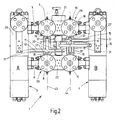
- ein weiteres Ausführungsbeispiel einer Schaltvorrichtung für einen Fluidstrom, insbesondere für die Leitung eines unter hohem Druck stehenden Fluids in zwei Behandlungseinrichtungen;
- Fig. 3 bis 9
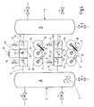
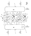
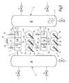
- jeweils eine schematische Seitenansicht der Behandlungseinrichtung mit jeweils einer mittig dargestellten schematischen Draufsicht auf die Schaltvorrichtung gemäß der Darstellung nach der
Fig. 1 in verschiedenen Betriebsphasen beim jeweiligen Umschalten des Fluidstroms von einer Behandlungseinrichtung zu der anderen Behandlungseinrichtung. - In der
Fig. 1 ist ein Ausführungsbeispiel einer Schaltvorrichtung 1 zur Leitung eines Fluids 2 gezeigt, das einen flüssigen oder gasförmigen, zu filtrierenden Prozessstrom darstellt, welcher auch Aerosole aufweisen kann. Das Fluid 2 kann wahlweise in eine erste oder eine zweite Behandlungseinrichtung 3 (= A) bzw. 4 (= B) geleitet werden. Die Behandlungseinrichtungen 3, 4 sind in dem gezeigten Ausführungsbeispiel jeweils mit einem Filtergehäuse ausgebildet, die entsprechende Filterelemente enthalten. Die Schaltvorrichtung 1 dient hierbei insbesondere zur Steuerung des Zuflusses von Fluid 2, über ein Ventil 22 wahlweise in die erste Behandlungseinrichtung 3 oder in die zweite Behandlungseinrichtung 4. - Die Behandlungseinrichtungen 3, 4 sind über eine erste fluidführende Verbindung 5 und eine zweite fluidführende Verbindung 6 miteinander fluidführend verbindbar oder wieder voneinander trennbar. Die fluidführenden Verbindungen 5, 6 sind als druckfeste Rohrleitungen mit Schraubflanschen zwischen den jeweiligen druckfesten Gehäusen 26, 27 der ersten Behandlungseinrichtung 3 und der zweiten Behandlungseinrichtung 4 angeordnet. Die erste fluidführende Verbindung 5 dient zur Abfuhr von filtriertem Fluid 2, während die zweite fluidführende Verbindung 6 zur Zufuhr von unfiltriertem Fluid 2 in die eine oder andere Behandlungseinrichtung 3, 4 vorgesehen ist.
- Die Abfuhr von filtriertem Fluid erfolgt über ein Ventil 21, das mittig, in der ersten fluidführenden Verbindung 5 angeordnet ist. Ebenso ist das Ventil 22 in etwa mittig in der zweiten fluidführenden Verbindung 6 angeordnet. Insgesamt befinden sich die beiden Ventile 21, 22 in jeweils einem Ventilblock 28, 29, mit jeweils zwei seitlich angrenzenden Verteilerventilen. In der ersten fluidführenden Verbindung 5 sind mithin zu beiden Seiten des Ventils 21 ein erstes Verteilerventil 7 und ein drittes Verteilerventil 13 in dem Ventilblock 28 angeordnet. In der zweiten fluidführenden Verbindung 6 sind zu beiden Seiten des Ventils 22 ein zweites und ein viertes Verteilerventil 8, 14 in dem weiteren Ventilblock 29 angeordnet. Die Verteilerventile 7, 13 und 8, 14 sind mit als Kugelsegmente ausgebildeten Ventilelementen 9, 10, 39, 40 versehen, deren Durchlassöffnungen 19, 20, 41, 42 jeweils T-förmig ausgestaltet sind (vgl.
Fig. 3 bis 9 ). - Das erste und das zweite Verteilerventil 7, 8 sind der ersten Behandlungseinrichtung 3 benachbart und dieser zugeordnet in dem Sinne, dass sie die jeweiligen fluidführenden Verbindungen 5, 6 zu der ersten Behandlungseinrichtung 3 sperren oder öffnen können. Das dritte und vierte Verteilerventil 13, 14 sind der zweiten Behandlungseinrichtung 4 in gleicher Funktionsweise zugeordnet. In dem gesperrten Zustand der der Behandlungseinrichtung 3 zugeordneten Verteilerventile 7 und 8 oder der der Behandlungseinrichtung 4 zugeordneten Verteilerventile 13 und 14 sind die Behandlungseinrichtungen 3 oder 4 jeweils entleerbar oder für andere Prozessschritte als dem Fluiddurchfluss nutzbar, wie etwa zu Wartungsarbeiten, zum Tausch von Prozessführungselementen, wie Filtern und dergleichen.
- Neben der Abfuhrfunktion von Fluid oder Reinigungsmitteln oder dergleichen Prozessstoffe hat das fünfte Ventil 21 mit Hilfe eines integrierten Nadelventils 36 noch die Aufgabe, den Druckausgleich in Vorbereitung der Umschaltung von einer Behandlungseinrichtung zur anderen in den fluidführenden Verbindungen 5, 6 zu bewirken. Alternativ oder ergänzend kann auch beim sechsten Ventil 22 ein dahingehendes Nadelventil vorgesehen sein. Die Ventilelemente 23, 24 des fünften und sechsten Ventils 21, 22 haben L-förmige Durchlassöffnungen 25, die somit ein Umschalten des Zufuhr- oder Abfuhr-Fluidstroms von der ersten Behandlungseinrichtung 3 und der zweiten Behandlungseinrichtung 4 entsprechend steuern können.
- Wie insbesondere die
Fig. 1 des Weiteren zeigt, sind das erste und zweite sowie das dritte und vierte Verteilerventil 7, 8, 13, 14 mit manuell betätigbaren Schalthebeln 11, 12, 15, 16 versehen. Die Schalthebel 11 und 15 des ersten und dritten Verteilerventils 7, 13 sind hängend an dem jeweiligen Ventilelement angeschraubt, während die Schalthebel 12, 16 in umgekehrter Weise zu den Schalthebeln 11, 15 gerichtet, an den betreffenden Ventilelementen der Verteilerventile 8, 14 von oben her angeschraubt sind. Jede Längsachse 18 eines zugeordneten Schalthebels ist, von dem Ventilelement ausgehend, zu ihrem jeweiligen freien Ende 17 hin betrachtet, gekröpft ausgebildet. Dadurch sind die freien Enden 17 räumlich eng zusammengeführt, allerdings ohne sich gegenseitig zu berühren. So lassen sich die jeweils freien Enden 17 des ersten und zweiten Schalthebels 11, 12 und die freien Enden 17 des dritten und vierten Schalthebels 15, 16 mit einer Hand gemeinsam greifen und synchron die Schalthebel von einer Schaltposition in die anderen führen. Vorzugsweise sind dabei keine Rastungen zu überwinden. - Das aus den dem ersten Verteilerventil 7 zugeordneten Schalthebel 11 und dem aus dem zweiten Verteilerventil 8 zugeordneten Schalthebel 12 gebildete Paar Schalthebel ist in einer senkrecht zu einer Drehachse 43 der Verteilerventile 7, 8 ausgerichteten Ebene angeordnet, die sich von der senkrecht zur Drehachse 44 ausgerichteten Ebene der Anordnung des Paares Schalthebel 15, 16 unterscheidet. Insbesondere ist mit Sicht auf
Fig. 1 das Paar Schalthebel 11, 12 unterhalb des Paares Schalthebel 15, 16 angeordnet, so dass die Schalthebel 11 und 12 unbehindert von den Schalthebeln 15 und 16, und zwar egal welche Position die Schalthebel 15, 16 einnehmen, von einer Bedienperson kollisionsfrei betätigbar sind. - Das fünfte und sechste Ventil 21, 22 bzw. deren Ventilelemente 23, 24 sind über eine Welle 30 zwangsgekoppelt und lassen sich nur gemeinsam verdrehen. Zu diesem Zweck weist die Welle 30 einen weiteren, handbetätigbaren Schalthebel 31 auf, der auf dieselbe Seite der Schaltvorrichtung 1 ragend gezeigt ist, wie die übrigen Schalthebel 11, 12, 15, 16, so dass die gesamte Schaltvorrichtung 1 von einer Seite der Schaltvorrichtung 1 her durch eine Bedienperson bedienbar ist.
- Bei der in der
Fig. 2 gezeigten weiteren Ausführungsform der erfindungsgemäßen Schaltvorrichtung sind von der in derFig. 1 gezeigten Ausführungsform abweichend die Schalthebel 11, 12, 15 und 16 als zweiarmige Hebel ausgeführt, so dass eine Betätigung der zugeordneten Verteilerventile sowohl von der in derFig. 2 gezeigten Bedienerseite der Schaltvorrichtung als auch von der gegenüberliegenden Prozessseite her von einer Bedienperson möglich ist. Der weitere Schalthebel 31, der die die Ventile 21 und 22 koppelnde Welle 30 zumindest teilweise durchsetzt, lässt sich durch die hierfür vorgesehene Aufnahme 38 in der Welle 30 in Richtung der Prozessseite der Schaltvorrichtung verschieben, so dass auch der weitere Schalthebel 31 in eine Position bringbar ist, in der er von der Prozessseite der Schaltvorrichtung her betätigbar ist. Die Schalthebel 11, 12, 15, 16 sind in der gezeigten Ausführungsform symmetrisch ausgebildet und in ihrem Zentrum jeweils mit den zugeordneten Verteilerventilen 7, 8, 13, 14 verbunden. Als Beispiel sei der Schalthebel 16 näher erläutert. Ausgehend von der Befestigung des Schalthebels 16 an dem Verteilerventil 14 erstrecken sich die beiden symmetrisch angeordneten Distanzabschnitte 37 im Wesentlichen in Richtung der Drehachse 44 des Verteilerventils 14 und bilden so als Schenkel zusammen mit dem nicht näher bezeichneten Befestigungsabschnitt des Schalthebels 16 an dem Verteilerventil 14 eine U-förmige Gestalt aus, wobei der Befestigungsabschnitt als ein die Schenkel verbindendes Joch ausgebildet ist. In Höhe der für den Schwenkbereich des Schalthebels 16 vorgesehenen Ebene sind symmetrisch die beiden sich jeweils bis zu ihren Enden 17 erstreckenden Arme des Schalthebels 16 abgekröpft. In analoger Weise ist der Schalthebel 15 des dritten Verteilerventils 13 bezüglich der Drehachse 44 des Verteilerventils 13 ausgeführt, wobei mit Sicht aufFig. 2 die Distanzabschnitte 37 des Schalthebels 15 sich ausgehend vom dritten Verteilerventil 13 nach unten hin erstrecken, so dass diese zusammen mit dem Befestigungsabschnitt des Schalthebels 15 eine nach unten hin geöffnete U-förmige Gestalt bilden. In analoger Weise sind auch die Schalthebel 11 des ersten Verteilerventils 7 und 12 des zweiten Verteilerventils 8 ausgebildet, wobei der Schalthebel 11 als Gleichteil des Schalthebels 16 und der Schalthebel 12 als Gleichteil des Schalthebels 15 ausgeführt ist. Mit Sicht aufFig. 2 sind die beiden Schalthebel 11, 12 symmetrisch zur Drehachse 43 der zugeordneten Verteilerventile 7 und 8 ausgebildet. Die U-förmige Gestalt der Distanzabschnitte 37 und des Befestigungsabschnitts des Schalthebels 12 ist von dem zweiten Verteilerventil 8 wegweisend, nach oben hin geöffnet, wohingegen die durch die Distanzabschnitte 37 und den Befestigungsabschnitt des Schalthebels 11 gebildete U-förmige Gestalt, von dem zugeordneten Verteilerventil 7 wegweisend, bei Sicht aufFig. 2 nach unten hin geöffnet ist. - Wie die schematisierten Draufsichten gemäß den Darstellungen nach den
Fig. 3 bis 9 zeigen, ist der mögliche Umschaltvorgang von einer Behandlungseinrichtung 3 zur andere Behandlungseinrichtung 4 über die Betätigung der jeweiligen Schalthebel unter Einsatz von Steuerscheiben 32, 33, 34 insoweit zwangsgekoppelt. Die Steuerscheiben 32, 33, 34 sind mit den jeweiligen, zuordenbaren Schalthebeln oder Ventilelementen fest verbunden und weisen jeweils einen kreissegmentförmigen Ausschnitt 35 an ihrem Umfangsrand auf. Der Ausschnitt 35 einer jeden Steuerscheibe kann mit einem Umfangsrand der jeweils benachbarten Steuerscheibe dahingehend zusammenwirken, dass eine Drehbewegung ermöglicht oder eben blockiert ist. - Die
Fig. 3 zeigt eine Betriebsposition der Schaltvorrichtung 1, in der die erste Behandlungseinrichtung 3 mit Fluid 2 über das sechste Ventil 22 und das zweite Verteilerventil 8 angeströmt wird. Das Fluid 2 verlässt über das erste Verteilerventil 7 und das fünfte Ventil 21 die dahingehend erste Behandlungseinrichtung 3. Die Steuerscheiben 32, 33 der genannten Ventile sind durch die Anlage der Steuerscheiben 32 mit ihren Abschnitten 35 an dem Umfangsrand der Steuerscheiben 33 blockiert. Die zweite Behandlungseinrichtung 4 ist drucklos und über das fünfte Ventil 21 und das dritte Verteilerventil in der ersten fluidführenden Verbindung 5 sowie über das sechste Ventil 22 und das vierte Verteilerventil 14 in der zweiten fluidführenden Verbindung 6 jeweils doppelt abgesperrt von der ersten Behandlungseinrichtung 3 und kann beispielsweise in der dahingehenden Betriebsphase gewartet werden. Die Orientierung der L-förmigen Durchlassöffnung 25 des Ventilelements 23 des fünften Ventils 21 sowie der T-förmigen Durchlassöffnung 41 des Ventilelements 39 des dritten Verteilerventils 13 führen zu der dahingehenden doppelten Absperrung in der ersten fluidführenden Leitung 5. Entsprechend führt die Orientierung der L-förmigen Durchlassöffnung 25 des Ventilelements 24 des sechsten Ventils 22 sowie die Orientierung der T-förmigen Durchlassöffnung 42 des Ventilelements 40 des vierten Verteilerventils 14 in der zweiten fluidführenden Verbindung 6 zu einer doppelten Absperrung der zweiten Behandlungseinrichtung 4 in der zweiten fluidführenden Verbindung 6. So kann in dieser Betriebsphase ein Austausch von nicht näher dargestellten Filterelementen (Altelement gegen Neuelement) stattfinden. In beiden Behandlungseinrichtungen 3, 4 sind ansonsten dieselben Prozessschritte, nämlich eine Filtrierung für das die Filterelemente zu durchströmende Fluid 2, gegebenenfalls ergänzt um eine Vor- und/oder Nachbehandlung durch einen Zyklonabscheider, vorgesehen. - Die weiteren
Fig. 4 bis 9 zeigen den Umschaltvorgang an der Schaltvorrichtung 1 von dem Betrieb der ersten Behandlungseinrichtung 3 zu der zweiten Behandlungseinrichtung 4. In derFig. 4 ist zunächst ein Entsperren der dritten und vierten Verteilerventile 13, 14 aufgezeigt. Deren Schalthebel 15, 16 werden von einer Bedienperson gemeinsam mit einer Hand und in Betrachtungsrichtung auf dieFig. 4 gesehen nach links verschwenkt. Wie derFig. 4 bei der gezeigten Draufsicht deutlich entnehmbar, kommt es hierbei zu einem Überkreuzen der Schalthebel 15 und 16 über den Schalthebel 31. Dadurch dass das Paar Schalthebel 15, 16 jedoch in einer von dem weiteren Schalthebel 31 unterschiedlichen Ebene angeordnet ist, führt die dahingehende Kreuzung nicht zu einer Kollision der Schalthebel 15, 16 mit dem weiteren Schalthebel 31. Im Vergleich zu der in derFig. 3 dargestellten Betriebsposition der Schaltvorrichtung 1 verbleiben die übrigen Verteilerventile 7, 8 sowie die Ventile 21, 22 in ihrer gezeigten Schaltposition. - In der
Fig. 5 ist ein nachfolgender Druckausgleich zwischen der ersten Behandlungseinrichtung 3 über das Nadelventil 36 gezeigt, das das fünfte Ventil 21 überbrückt. Durch den Druckausgleich wird die zweite Behandlungseinrichtung 4 auf Betriebsdruck gebracht und mit Fluid 2 gefüllt. - Bei der Betriebsposition gemäß
Fig. 6 ist der Druckausgleichsvorgang abgeschlossen, und die zweite Behandlungseinrichtung 4 ist nun komplett mit Fluid 2 gefüllt und steht unter Betriebsdruck. - In der
Fig. 7 ist das Umschalten von dem Betrieb der ersten Behandlungseinrichtung 3 zu der zweiten Behandlungseinrichtung 4 gezeigt. Dazu wird der weitere Schalthebel 31 an der Welle 30 mit Sicht aufFig. 7 von rechts nach links verschwenkt. Hierbei kommt es zu einer Kreuzung des weiteren Schalthebels 31 über das Paar Schalthebel 11, 12, was aber durch die erfindungsgemäße Anordnung des Paares Schalthebel 11, 12 in einer Ebene, die sich von der Ebene des weiteren Schalthebels 31 unterscheidet, zu keiner Kollision führt. Das fünfte und das sechste Ventil 21, 22 lenken den Fluidstrom dadurch zu der zweiten Behandlungseinrichtung 4, die nun von Fluid 2 durchströmt wird. Die erste Behandlungseinrichtung 3 steht zwar noch unter Druck, doch tritt hier keine Strömung mehr auf. - In
Fig. 8 erfolgt die zusätzlich Absperrung der ersten Behandlungseinrichtung 3 durch Verschwenken des Paares Schalthebel 11, 12 von rechts nach links, wie beim Vergleich der Draufsichten vonFiguren 7 und8 deutlich wird. - In der
Fig. 9 wird das Absenken des Druckes in der ersten Behandlungseinrichtung 3 gezeigt. Die auf den Ventilelementen 9, 10, 23, 24, 39, 40 gezeigten Schaltsymbole stellen den jeweiligen Schaltvorgang sinnfällig für den Betrachter dar.
Claims (11)
- Schaltvorrichtung für einen Fluidstrom, insbesondere für die Leitung eines unter hohem Druck stehenden Fluids (2) von einer ersten Behandlungseinrichtung (3) zu einer zweiten Behandlungseinrichtung (4), wobei in jeder Behandlungseinrichtung (3, 4) das Fluid (2) einem chemischen und/oder physikalischen Prozessschritt unterzogen werden kann, mit einer ersten fluidführenden Verbindung (5) und einer zweiten fluidführenden Verbindung (6) zwischen der ersten und der zweiten Behandlungseinrichtung (3, 4) und mit zumindest einem ersten Verteilerventil (7) und einem dritten Verteilerventil (13) in der ersten fluidführenden Verbindung (5) sowie einem zweiten Verteilerventil (8) und einem vierten Verteilerventil (14) in der zweiten fluidführenden Verbindung (6), wobei die jeweilige Schaltposition der Ventilelemente (9, 10, 39, 40) der Verteilerventile (7, 8, 13, 14) durch zumindest je einen Schalthebel (11, 12, 15, 16) veränderbar ist, dadurch gekennzeichnet, dass ein den ersten und zweiten Verteilerventilen (7, 8) zugeordnetes erstes Paar Schalthebel (11, 12) und ein den dritten und vierten Verteilerventilen (13, 14) zugeordnetes zweites Paar Schalthebel (15, 16) vorgesehen und derart in unterschiedlichen Ebenen angeordnet sind, dass die Schalthebel (11, 12) des erstes Paares unbehindert von den Schalthebeln (15, 16) des zweiten Paares, und umgekehrt, von einer Bedienperson betätigbar sind.
- Schaltvorrichtung nach Anspruch 1, dadurch gekennzeichnet, dass das erste (11, 12) und das zweite (15, 16) Paar Schalthebel für das Betätigen des jeweils zugeordneten Verteilerventilpaares (7, 8; 13, 14) von einer Fluid (2) durchlassenden Stellung in eine Fluid (2) sperrende Stellung und umgekehrt einen dem ersten Paar Schalthebel (11, 12) zugeordneten ersten Schwenkbereich und einen dem zweiten Paar Schalthebel (15, 16) zugeordneten zweiten Schwenkbereich definieren, die sich in der Projektion teilweise überlagern und dass durch die Anordnung des ersten (11, 12) und des zweiten (15, 16) Paares Schalthebel in unterschiedlichen Ebenen jedes der beiden Paare in jeder Betätigungsstellung kollisionsfrei in den Schwenkbereich des jeweils anderen Paares Schalthebel eintreten kann.
- Schaltvorrichtung nach einem der vorhergehenden Ansprüche, dadurch gekennzeichnet, dass die Schalthebel (11, 12) des erstes Paares und die Schalthebel (15, 16) des zweiten Paares derart angeordnet sind, dass beide Schalthebel (11, 12; 15, 16) eines Paares jeweils mit einer Hand einer Bedienperson über den gesamten Schwenkbereich gemeinsam betätigbar sind.
- Schaltvorrichtung nach einem der vorhergehenden Ansprüche, dadurch gekennzeichnet, dass die Schalthebel (11, 12, 15, 16) zur Anordnung in den unterschiedlichen Ebenen jeweils einen gegenüber ihren freien Enden abgekröpften und im Wesentlichen in Richtung der Drehachse (43, 44) des zugeordneten Verteilerventils (7, 8, 13, 14) verlaufenden Distanzabschnitt (37) aufweisen.
- Schaltvorrichtung nach Anspruch 4, dadurch gekennzeichnet, dass die Distanzabschnitte (37) der Schalthebel (11, 12; 15, 16) eines Paares eine unterschiedliche Längserstreckung aufweisen.
- Schaltvorrichtung nach einem der vorhergehenden Ansprüche, dadurch gekennzeichnet, dass die Schalthebel (11, 12, 15, 16) jeweils als zweiarmige Hebel ausgeführt sind, an denen die Bedienperson angreift und bei denen die beiden Arme des Hebels, jeweils bezogen auf die Drehachse (43, 44) des zugeordneten Verteilerventils (7, 8, 13, 14), diametral einander gegenüberliegend angeordnet sind.
- Schaltvorrichtung nach einem der vorhergehenden Ansprüche, dadurch gekennzeichnet, dass der eine Schalthebel (11) des ersten Paares als Gleichteil des einen Schalthebels (16) des zweiten Paares und dass der andere Schalthebel (12) des ersten Paares als Gleichteil des anderen Schalthebels (15) des zweiten Paares ausgebildet ist.
- Schaltvorrichtung nach einem der vorhergehenden Ansprüche, dadurch gekennzeichnet, dass ein fünftes Ventil (21) in der ersten fluidführenden Verbindung (5) zwischen dem ersten und dem dritten Verteilerventil (7, 13) angeordnet ist und ein sechstes Ventil (22) zwischen dem zweiten und dem vierten Verteilerventil (8, 14) in der zweiten fluidführenden Verbindung (6) angeordnet ist.
- Schaltvorrichtung nach Anspruch 8, dadurch gekennzeichnet, dass das fünfte Ventil (21) und das sechste Ventil (22) über eine sie koppelnde Welle (30) betätigbar sind und dass an der Welle (30) ein weiterer Schalthebel (31) angreift, dessen Schwenkbereich, durch die Anordnung des weiteren Schalthebels (31) in einer von den Ebenen der Schwenkbereiche des ersten Paares Schalthebel (11, 12) und des zweiten Paares Schalthebel (15, 16) unterschiedlichen Ebene, kollisionsfrei in den Schwenkbereich des ersten (11, 12) und des zweiten (15, 16) Paares Schalthebel eintreten kann.
- Schaltvorrichtung nach Anspruch 9, dadurch gekennzeichnet, dass der weitere Schalthebel (31) zur gemeinsamen Betätigung des fünften (21) und des sechsten (22) Ventils stangenförmig ausgebildet ist und in einer Aufnahme (38) geführt die Welle (30) quer zu deren Längserstreckung zumindest teilweise durchsetzt, so dass der weitere Schalthebel (31) in gegenüberliegende Bedienstellungen bringbar ist.
- Schaltvorrichtung nach einem der vorhergehenden Ansprüche 8-10, dadurch gekennzeichnet, dass von der Prozessseite der Schaltvorrichtung her der Zufluss des Fluids (2) über das sechste Ventil (22) in der zweiten Fluid (2) führenden Verbindung (6) steuerbar ist und dass die Schalthebel (11, 12, 15, 16) und der weitere Schalthebel (31) von der der Prozessseite gegenüberliegenden Bedienerseite der Schaltvorrichtung her durch eine Bedienperson betätigbar sind.
Priority Applications (1)
| Application Number | Priority Date | Filing Date | Title |
|---|---|---|---|
| PL11724562T PL2585742T3 (pl) | 2010-06-25 | 2011-06-10 | Urządzenie przełączające dla strumienia płynu |
Applications Claiming Priority (2)
| Application Number | Priority Date | Filing Date | Title |
|---|---|---|---|
| DE102010025153A DE102010025153A1 (de) | 2010-06-25 | 2010-06-25 | Schaltvorrichtung für einen Fluidstrom |
| PCT/EP2011/002852 WO2011160780A1 (de) | 2010-06-25 | 2011-06-10 | Schaltvorrichtung für einen fluidstrom |
Publications (2)
| Publication Number | Publication Date |
|---|---|
| EP2585742A1 EP2585742A1 (de) | 2013-05-01 |
| EP2585742B1 true EP2585742B1 (de) | 2014-04-02 |
Family
ID=44343998
Family Applications (1)
| Application Number | Title | Priority Date | Filing Date |
|---|---|---|---|
| EP11724562.1A Not-in-force EP2585742B1 (de) | 2010-06-25 | 2011-06-10 | Schaltvorrichtung für einen fluidstrom |
Country Status (11)
| Country | Link |
|---|---|
| US (1) | US9004106B2 (de) |
| EP (1) | EP2585742B1 (de) |
| KR (1) | KR101890101B1 (de) |
| CN (1) | CN102985732B (de) |
| CA (1) | CA2803681C (de) |
| DE (1) | DE102010025153A1 (de) |
| MY (1) | MY163199A (de) |
| PL (1) | PL2585742T3 (de) |
| RU (1) | RU2562883C2 (de) |
| SG (1) | SG186735A1 (de) |
| WO (1) | WO2011160780A1 (de) |
Families Citing this family (12)
| Publication number | Priority date | Publication date | Assignee | Title |
|---|---|---|---|---|
| USD244243S (en) * | 1975-12-17 | 1977-05-10 | Interstate Industries, Inc. | Shelf module, or similar article |
| US9366347B2 (en) * | 2012-03-22 | 2016-06-14 | Mogas Industries, Inc. | Multiport severe service ball valve |
| EP3153221A1 (de) | 2015-10-09 | 2017-04-12 | Total Marketing Services | Siox-filtrationseinheit und verfahren zum betreiben der siox-filtrationseinheit |
| WO2017125914A1 (en) * | 2016-01-18 | 2017-07-27 | Ham-Let (Israel - Canada ) Ltd. | Stream switching valve with synchronizing mechanism |
| CN108662199B (zh) * | 2017-03-28 | 2021-12-14 | 毛高闻 | 一种反冲过滤系统用四通阀 |
| US10160149B2 (en) * | 2017-04-05 | 2018-12-25 | Plastixs, LLC | Access to cooling manifold valve controls in injection molding operations |
| US11679348B2 (en) * | 2017-12-29 | 2023-06-20 | Enercorp Engineered Solutions Inc. | Horizontal sand separator assembly |
| USD894328S1 (en) * | 2018-03-22 | 2020-08-25 | Mechanical Manufacturing Corporation | Modular filter system for enhanced user access |
| DE102018108013B4 (de) * | 2018-04-05 | 2021-05-06 | Hanon Systems | Vorrichtungen zum Regeln eines Durchflusses und Verteilen eines Fluids in einem Fluidkreislauf |
| CN112178245B (zh) * | 2019-07-05 | 2024-09-13 | 金德创新技术股份有限公司 | 双动力源复合控制装置 |
| US20220323886A1 (en) * | 2021-04-08 | 2022-10-13 | Chevron U.S.A. Inc. | Filtration System and Method |
| US12320433B2 (en) | 2021-08-25 | 2025-06-03 | Swagelok Company | Actuator arrangement for multi-valve assembly |
Family Cites Families (34)
| Publication number | Priority date | Publication date | Assignee | Title |
|---|---|---|---|---|
| US746896A (en) * | 1903-06-19 | 1903-12-15 | James Stott | Valve or tap. |
| US844438A (en) * | 1906-07-28 | 1907-02-19 | Cummings Filter Co | Filtering apparatus. |
| GB162116A (en) * | 1920-02-06 | 1921-04-28 | Frank Ernest Hands | Improvements in and connected with gas cocks |
| US1654355A (en) * | 1927-03-30 | 1927-12-27 | Colt S Mfg Co | Dish-washing machine |
| US1898569A (en) * | 1931-09-21 | 1933-02-21 | Carl A Pearson | Interlocking valve construction |
| US2489362A (en) * | 1946-09-11 | 1949-11-29 | Tri Clover Machine Co | Line filter |
| US2685276A (en) * | 1951-04-05 | 1954-08-03 | Charles P Dyken | Valve operated pressure control |
| US2921687A (en) * | 1958-05-06 | 1960-01-19 | Andale Co | Means for simultaneously actuating opposed disc valves in a duplex strainer |
| US3679060A (en) * | 1970-09-08 | 1972-07-25 | Xomox Corp | Duplex strainer construction |
| US3792612A (en) * | 1973-02-01 | 1974-02-19 | Chevron Res | Safety interlock for a particulate solids sampler |
| US3935108A (en) * | 1974-10-07 | 1976-01-27 | Parks-Cramer Company | Changeover valves with bypass and bent valving |
| SU971430A1 (ru) * | 1976-03-19 | 1982-11-07 | за вители / ..,, ; / П ./ / ,/м,о. /5/ Л;;.л | Фильтрационна установка дл очистки жидкостей от взвешенных примесей |
| US4281683A (en) * | 1978-12-11 | 1981-08-04 | Poly-Glas Systems | Modular multiple-fluid component selection and delivery system |
| US4336919A (en) * | 1979-09-26 | 1982-06-29 | Lake & Elliot Incorporated | Ball valve |
| US4429711A (en) * | 1982-03-08 | 1984-02-07 | Anderson, Greenwood & Co. | Multivalve manifold interlock and control system |
| US4496463A (en) * | 1983-12-08 | 1985-01-29 | Mueller Steam Specialty, A Division Of Core Industries, Inc. | Duplex strainer |
| US4611626A (en) * | 1984-09-11 | 1986-09-16 | Logsdon Duane D | Fluid control valve |
| SU1452552A1 (ru) * | 1986-10-03 | 1989-01-23 | Казанский инженерно-строительный институт | Фильтровальна установка |
| US4823843A (en) * | 1988-06-01 | 1989-04-25 | Aptec, Inc. | Valve apparatus |
| DE8907211U1 (de) * | 1989-06-13 | 1989-07-27 | Hydac Filtertechnik GmbH, 6603 Sulzbach | Umschaltarmatur |
| GB2236829A (en) * | 1989-10-14 | 1991-04-17 | Oliver Engineering Limited | A valve assembly |
| US5335686A (en) * | 1993-08-18 | 1994-08-09 | Isringhausen Carl L | Steam trap |
| US5383491A (en) * | 1994-01-19 | 1995-01-24 | Heilman; David D. | Dual tandem flow diverter valve system |
| CH689061A5 (de) * | 1994-12-05 | 1998-08-31 | Interapp Ag | Handhebel zum Betaetigen einer um eine Drehachse drehbaren Vorrichtung und Verwendung desselben. |
| US5779771A (en) * | 1995-11-07 | 1998-07-14 | Calgon Carbon Corporation | Rotating flow distributor assembly for use in continuously distributing decontamination and regeneration fluid flow |
| US5893969A (en) * | 1997-12-29 | 1999-04-13 | Mechanical Manufacturing Corp. | Filter vessel safety apparatus |
| NL1013330C2 (nl) * | 1999-10-18 | 2001-04-19 | Indufil B V | Schakelinrichting en mediumstroom naar keuze door een eerste of tweede behandelorgaan te leiden. |
| NL1014456C2 (nl) * | 2000-02-21 | 2001-08-22 | Indufil B V | Uit een stel schakelkranen opgebouwde schakeleenheid geschikt om een eerste en een tweede medium naar keuze door ÚÚn van twee platenkoelers te doen stromen. |
| US6935913B2 (en) | 2000-10-27 | 2005-08-30 | Science Applications International Corporation | Method for on-line testing of a light emitting panel |
| US6558554B1 (en) * | 2001-12-12 | 2003-05-06 | Eastman Kodak Company | Method for switching filters on-line without bubbles and with zero liquid waste |
| US6935613B1 (en) * | 2002-03-05 | 2005-08-30 | Oslin Nation Co. | Compact integrated flanged isolator ball valve |
| US7223298B2 (en) * | 2005-03-17 | 2007-05-29 | Pgr Filters, L.L.C. | Filter assembly for pipelines |
| US7896959B1 (en) * | 2005-04-29 | 2011-03-01 | Schopf Jr Robert W | Filtration apparatus |
| DE202005009175U1 (de) * | 2005-06-10 | 2006-07-27 | Boll & Kirch Filterbau Gmbh | Schaltvorrichtung für Mehrfachbehandlungsvorrichtungen |
-
2010
- 2010-06-25 DE DE102010025153A patent/DE102010025153A1/de not_active Withdrawn
-
2011
- 2011-06-10 CN CN201180031405.6A patent/CN102985732B/zh not_active Expired - Fee Related
- 2011-06-10 CA CA2803681A patent/CA2803681C/en active Active
- 2011-06-10 EP EP11724562.1A patent/EP2585742B1/de not_active Not-in-force
- 2011-06-10 RU RU2012155157/06A patent/RU2562883C2/ru active
- 2011-06-10 SG SG2012092540A patent/SG186735A1/en unknown
- 2011-06-10 PL PL11724562T patent/PL2585742T3/pl unknown
- 2011-06-10 MY MYPI2012701245A patent/MY163199A/en unknown
- 2011-06-10 WO PCT/EP2011/002852 patent/WO2011160780A1/de not_active Ceased
- 2011-06-10 KR KR1020137001886A patent/KR101890101B1/ko not_active Expired - Fee Related
- 2011-06-10 US US13/261,531 patent/US9004106B2/en active Active
Also Published As
| Publication number | Publication date |
|---|---|
| CN102985732A (zh) | 2013-03-20 |
| PL2585742T3 (pl) | 2014-09-30 |
| RU2012155157A (ru) | 2014-07-27 |
| CA2803681A1 (en) | 2011-12-29 |
| CA2803681C (en) | 2017-03-07 |
| CN102985732B (zh) | 2017-10-17 |
| KR20130089237A (ko) | 2013-08-09 |
| RU2562883C2 (ru) | 2015-09-10 |
| EP2585742A1 (de) | 2013-05-01 |
| DE102010025153A1 (de) | 2011-12-29 |
| US9004106B2 (en) | 2015-04-14 |
| KR101890101B1 (ko) | 2018-08-22 |
| WO2011160780A1 (de) | 2011-12-29 |
| SG186735A1 (en) | 2013-02-28 |
| MY163199A (en) | 2017-08-15 |
| US20130068979A1 (en) | 2013-03-21 |
Similar Documents
| Publication | Publication Date | Title |
|---|---|---|
| EP2585742A1 (de) | Schaltvorrichtung für einen fluidstrom | |
| EP2956225B1 (de) | Filtereinrichtung | |
| DE102006044744C5 (de) | Wasserfiltervorrichtung mit Verschlüsselungsstruktur | |
| EP2236874B2 (de) | Membranventil | |
| DE102007017388B4 (de) | Vorrichtung zur Behandlung von Wasser, insbesondere Filtervorrichtung, und Kartusche | |
| EP2692954A1 (de) | Mehrflutige Auslaufarmatur mit Schwenkauslauf | |
| DE102014110550B4 (de) | Regelarmatur | |
| DE102007019064B3 (de) | Drehschieber | |
| DE102013109587A1 (de) | Thermostatventil für eine Verbrennungskraftmaschine | |
| DE60005552T2 (de) | Schaltvorrichtung um einen fluidstrom nach wahl durch eine erste oder zweite behandlungsvorrichtung zu führen | |
| DE2311840C2 (de) | Mischventil für zwei Fluidströmungen | |
| EP2577121B1 (de) | Schaltvorrichtung zur leitung eines fluids | |
| DE102009035551A1 (de) | Kurvengetriebe | |
| WO2016162083A1 (de) | Filtervorrichtung | |
| EP2212596A1 (de) | Kükenhahn | |
| EP3643562B1 (de) | Fahrzeugsitzelement für einen fahrzeugsitz mit einer restfederwegverstelleinrichtung | |
| DE102016009525A1 (de) | Ventil | |
| EP2854985B1 (de) | Filtervorrichtung für fluide | |
| EP3524862B1 (de) | Umschaltvorrichtung | |
| WO2024211950A1 (de) | Steckverbinder zur verbindung einer ersten fluidleitung mit einer zweiten fluidleitung | |
| DE202009001923U1 (de) | Anschlussarmatur für Ionentauscher | |
| DE102004059926B3 (de) | Rückschlagventil mit unterschiedlichen Flussrichtungen | |
| EP3059478B1 (de) | Vorrichtung zum anzeigen und/oder kontrollieren von fluiden | |
| EP3270020A1 (de) | Vorrichtung zur befestigung eines ventils | |
| DE202023102797U1 (de) | Rückspülfilteranordnung |
Legal Events
| Date | Code | Title | Description |
|---|---|---|---|
| PUAI | Public reference made under article 153(3) epc to a published international application that has entered the european phase |
Free format text: ORIGINAL CODE: 0009012 |
|
| 17P | Request for examination filed |
Effective date: 20121110 |
|
| AK | Designated contracting states |
Kind code of ref document: A1 Designated state(s): AL AT BE BG CH CY CZ DE DK EE ES FI FR GB GR HR HU IE IS IT LI LT LU LV MC MK MT NL NO PL PT RO RS SE SI SK SM TR |
|
| DAX | Request for extension of the european patent (deleted) | ||
| GRAP | Despatch of communication of intention to grant a patent |
Free format text: ORIGINAL CODE: EPIDOSNIGR1 |
|
| RIC1 | Information provided on ipc code assigned before grant |
Ipc: F16K 11/20 20060101AFI20131125BHEP Ipc: F16K 31/44 20060101ALI20131125BHEP Ipc: B01D 35/12 20060101ALI20131125BHEP |
|
| INTG | Intention to grant announced |
Effective date: 20131219 |
|
| GRAS | Grant fee paid |
Free format text: ORIGINAL CODE: EPIDOSNIGR3 |
|
| GRAA | (expected) grant |
Free format text: ORIGINAL CODE: 0009210 |
|
| AK | Designated contracting states |
Kind code of ref document: B1 Designated state(s): AL AT BE BG CH CY CZ DE DK EE ES FI FR GB GR HR HU IE IS IT LI LT LU LV MC MK MT NL NO PL PT RO RS SE SI SK SM TR |
|
| REG | Reference to a national code |
Ref country code: GB Ref legal event code: FG4D Free format text: NOT ENGLISH |
|
| REG | Reference to a national code |
Ref country code: AT Ref legal event code: REF Ref document number: 660343 Country of ref document: AT Kind code of ref document: T Effective date: 20140415 Ref country code: CH Ref legal event code: EP Ref country code: CH Ref legal event code: NV Representative=s name: ISLER AND PEDRAZZINI AG, CH |
|
| REG | Reference to a national code |
Ref country code: IE Ref legal event code: FG4D Free format text: LANGUAGE OF EP DOCUMENT: GERMAN |
|
| REG | Reference to a national code |
Ref country code: DE Ref legal event code: R096 Ref document number: 502011002618 Country of ref document: DE Effective date: 20140515 |
|
| REG | Reference to a national code |
Ref country code: NL Ref legal event code: T3 |
|
| REG | Reference to a national code |
Ref country code: LT Ref legal event code: MG4D |
|
| REG | Reference to a national code |
Ref country code: PL Ref legal event code: T3 |
|
| PG25 | Lapsed in a contracting state [announced via postgrant information from national office to epo] |
Ref country code: CY Free format text: LAPSE BECAUSE OF FAILURE TO SUBMIT A TRANSLATION OF THE DESCRIPTION OR TO PAY THE FEE WITHIN THE PRESCRIBED TIME-LIMIT Effective date: 20140402 Ref country code: NO Free format text: LAPSE BECAUSE OF FAILURE TO SUBMIT A TRANSLATION OF THE DESCRIPTION OR TO PAY THE FEE WITHIN THE PRESCRIBED TIME-LIMIT Effective date: 20140702 Ref country code: IS Free format text: LAPSE BECAUSE OF FAILURE TO SUBMIT A TRANSLATION OF THE DESCRIPTION OR TO PAY THE FEE WITHIN THE PRESCRIBED TIME-LIMIT Effective date: 20140802 Ref country code: CZ Free format text: LAPSE BECAUSE OF FAILURE TO SUBMIT A TRANSLATION OF THE DESCRIPTION OR TO PAY THE FEE WITHIN THE PRESCRIBED TIME-LIMIT Effective date: 20140402 Ref country code: GR Free format text: LAPSE BECAUSE OF FAILURE TO SUBMIT A TRANSLATION OF THE DESCRIPTION OR TO PAY THE FEE WITHIN THE PRESCRIBED TIME-LIMIT Effective date: 20140703 Ref country code: LT Free format text: LAPSE BECAUSE OF FAILURE TO SUBMIT A TRANSLATION OF THE DESCRIPTION OR TO PAY THE FEE WITHIN THE PRESCRIBED TIME-LIMIT Effective date: 20140402 Ref country code: BG Free format text: LAPSE BECAUSE OF FAILURE TO SUBMIT A TRANSLATION OF THE DESCRIPTION OR TO PAY THE FEE WITHIN THE PRESCRIBED TIME-LIMIT Effective date: 20140702 Ref country code: FI Free format text: LAPSE BECAUSE OF FAILURE TO SUBMIT A TRANSLATION OF THE DESCRIPTION OR TO PAY THE FEE WITHIN THE PRESCRIBED TIME-LIMIT Effective date: 20140402 |
|
| PG25 | Lapsed in a contracting state [announced via postgrant information from national office to epo] |
Ref country code: HR Free format text: LAPSE BECAUSE OF FAILURE TO SUBMIT A TRANSLATION OF THE DESCRIPTION OR TO PAY THE FEE WITHIN THE PRESCRIBED TIME-LIMIT Effective date: 20140402 Ref country code: ES Free format text: LAPSE BECAUSE OF FAILURE TO SUBMIT A TRANSLATION OF THE DESCRIPTION OR TO PAY THE FEE WITHIN THE PRESCRIBED TIME-LIMIT Effective date: 20140402 Ref country code: SE Free format text: LAPSE BECAUSE OF FAILURE TO SUBMIT A TRANSLATION OF THE DESCRIPTION OR TO PAY THE FEE WITHIN THE PRESCRIBED TIME-LIMIT Effective date: 20140402 Ref country code: RS Free format text: LAPSE BECAUSE OF FAILURE TO SUBMIT A TRANSLATION OF THE DESCRIPTION OR TO PAY THE FEE WITHIN THE PRESCRIBED TIME-LIMIT Effective date: 20140402 Ref country code: LV Free format text: LAPSE BECAUSE OF FAILURE TO SUBMIT A TRANSLATION OF THE DESCRIPTION OR TO PAY THE FEE WITHIN THE PRESCRIBED TIME-LIMIT Effective date: 20140402 |
|
| PG25 | Lapsed in a contracting state [announced via postgrant information from national office to epo] |
Ref country code: PT Free format text: LAPSE BECAUSE OF FAILURE TO SUBMIT A TRANSLATION OF THE DESCRIPTION OR TO PAY THE FEE WITHIN THE PRESCRIBED TIME-LIMIT Effective date: 20140804 |
|
| REG | Reference to a national code |
Ref country code: DE Ref legal event code: R097 Ref document number: 502011002618 Country of ref document: DE |
|
| PG25 | Lapsed in a contracting state [announced via postgrant information from national office to epo] |
Ref country code: EE Free format text: LAPSE BECAUSE OF FAILURE TO SUBMIT A TRANSLATION OF THE DESCRIPTION OR TO PAY THE FEE WITHIN THE PRESCRIBED TIME-LIMIT Effective date: 20140402 Ref country code: DK Free format text: LAPSE BECAUSE OF FAILURE TO SUBMIT A TRANSLATION OF THE DESCRIPTION OR TO PAY THE FEE WITHIN THE PRESCRIBED TIME-LIMIT Effective date: 20140402 Ref country code: RO Free format text: LAPSE BECAUSE OF FAILURE TO SUBMIT A TRANSLATION OF THE DESCRIPTION OR TO PAY THE FEE WITHIN THE PRESCRIBED TIME-LIMIT Effective date: 20140402 Ref country code: MC Free format text: LAPSE BECAUSE OF FAILURE TO SUBMIT A TRANSLATION OF THE DESCRIPTION OR TO PAY THE FEE WITHIN THE PRESCRIBED TIME-LIMIT Effective date: 20140402 Ref country code: LU Free format text: LAPSE BECAUSE OF FAILURE TO SUBMIT A TRANSLATION OF THE DESCRIPTION OR TO PAY THE FEE WITHIN THE PRESCRIBED TIME-LIMIT Effective date: 20140610 Ref country code: SK Free format text: LAPSE BECAUSE OF FAILURE TO SUBMIT A TRANSLATION OF THE DESCRIPTION OR TO PAY THE FEE WITHIN THE PRESCRIBED TIME-LIMIT Effective date: 20140402 |
|
| PLBE | No opposition filed within time limit |
Free format text: ORIGINAL CODE: 0009261 |
|
| STAA | Information on the status of an ep patent application or granted ep patent |
Free format text: STATUS: NO OPPOSITION FILED WITHIN TIME LIMIT |
|
| 26N | No opposition filed |
Effective date: 20150106 |
|
| REG | Reference to a national code |
Ref country code: IE Ref legal event code: MM4A |
|
| REG | Reference to a national code |
Ref country code: DE Ref legal event code: R097 Ref document number: 502011002618 Country of ref document: DE Effective date: 20150106 |
|
| PG25 | Lapsed in a contracting state [announced via postgrant information from national office to epo] |
Ref country code: IE Free format text: LAPSE BECAUSE OF NON-PAYMENT OF DUE FEES Effective date: 20140610 |
|
| PG25 | Lapsed in a contracting state [announced via postgrant information from national office to epo] |
Ref country code: RS Free format text: LAPSE BECAUSE OF FAILURE TO SUBMIT A TRANSLATION OF THE DESCRIPTION OR TO PAY THE FEE WITHIN THE PRESCRIBED TIME-LIMIT Effective date: 20141119 |
|
| PG25 | Lapsed in a contracting state [announced via postgrant information from national office to epo] |
Ref country code: SI Free format text: LAPSE BECAUSE OF FAILURE TO SUBMIT A TRANSLATION OF THE DESCRIPTION OR TO PAY THE FEE WITHIN THE PRESCRIBED TIME-LIMIT Effective date: 20140402 |
|
| PGFP | Annual fee paid to national office [announced via postgrant information from national office to epo] |
Ref country code: CH Payment date: 20150610 Year of fee payment: 5 |
|
| PG25 | Lapsed in a contracting state [announced via postgrant information from national office to epo] |
Ref country code: MT Free format text: LAPSE BECAUSE OF FAILURE TO SUBMIT A TRANSLATION OF THE DESCRIPTION OR TO PAY THE FEE WITHIN THE PRESCRIBED TIME-LIMIT Effective date: 20140402 |
|
| REG | Reference to a national code |
Ref country code: FR Ref legal event code: PLFP Year of fee payment: 6 |
|
| PG25 | Lapsed in a contracting state [announced via postgrant information from national office to epo] |
Ref country code: SM Free format text: LAPSE BECAUSE OF FAILURE TO SUBMIT A TRANSLATION OF THE DESCRIPTION OR TO PAY THE FEE WITHIN THE PRESCRIBED TIME-LIMIT Effective date: 20140402 |
|
| PG25 | Lapsed in a contracting state [announced via postgrant information from national office to epo] |
Ref country code: TR Free format text: LAPSE BECAUSE OF FAILURE TO SUBMIT A TRANSLATION OF THE DESCRIPTION OR TO PAY THE FEE WITHIN THE PRESCRIBED TIME-LIMIT Effective date: 20140402 Ref country code: HU Free format text: LAPSE BECAUSE OF FAILURE TO SUBMIT A TRANSLATION OF THE DESCRIPTION OR TO PAY THE FEE WITHIN THE PRESCRIBED TIME-LIMIT; INVALID AB INITIO Effective date: 20110610 Ref country code: BE Free format text: LAPSE BECAUSE OF FAILURE TO SUBMIT A TRANSLATION OF THE DESCRIPTION OR TO PAY THE FEE WITHIN THE PRESCRIBED TIME-LIMIT Effective date: 20140630 |
|
| REG | Reference to a national code |
Ref country code: CH Ref legal event code: PL |
|
| PG25 | Lapsed in a contracting state [announced via postgrant information from national office to epo] |
Ref country code: CH Free format text: LAPSE BECAUSE OF NON-PAYMENT OF DUE FEES Effective date: 20160630 Ref country code: LI Free format text: LAPSE BECAUSE OF NON-PAYMENT OF DUE FEES Effective date: 20160630 |
|
| REG | Reference to a national code |
Ref country code: FR Ref legal event code: PLFP Year of fee payment: 7 |
|
| REG | Reference to a national code |
Ref country code: AT Ref legal event code: MM01 Ref document number: 660343 Country of ref document: AT Kind code of ref document: T Effective date: 20160610 |
|
| PG25 | Lapsed in a contracting state [announced via postgrant information from national office to epo] |
Ref country code: AT Free format text: LAPSE BECAUSE OF NON-PAYMENT OF DUE FEES Effective date: 20160610 |
|
| REG | Reference to a national code |
Ref country code: FR Ref legal event code: PLFP Year of fee payment: 8 |
|
| PG25 | Lapsed in a contracting state [announced via postgrant information from national office to epo] |
Ref country code: MK Free format text: LAPSE BECAUSE OF FAILURE TO SUBMIT A TRANSLATION OF THE DESCRIPTION OR TO PAY THE FEE WITHIN THE PRESCRIBED TIME-LIMIT Effective date: 20140402 |
|
| PG25 | Lapsed in a contracting state [announced via postgrant information from national office to epo] |
Ref country code: AL Free format text: LAPSE BECAUSE OF FAILURE TO SUBMIT A TRANSLATION OF THE DESCRIPTION OR TO PAY THE FEE WITHIN THE PRESCRIBED TIME-LIMIT Effective date: 20140402 |
|
| PGFP | Annual fee paid to national office [announced via postgrant information from national office to epo] |
Ref country code: FR Payment date: 20210413 Year of fee payment: 11 |
|
| PGFP | Annual fee paid to national office [announced via postgrant information from national office to epo] |
Ref country code: GB Payment date: 20210421 Year of fee payment: 11 |
|
| PGFP | Annual fee paid to national office [announced via postgrant information from national office to epo] |
Ref country code: NL Payment date: 20220627 Year of fee payment: 12 Ref country code: IT Payment date: 20220614 Year of fee payment: 12 Ref country code: DE Payment date: 20220630 Year of fee payment: 12 |
|
| PGFP | Annual fee paid to national office [announced via postgrant information from national office to epo] |
Ref country code: PL Payment date: 20220415 Year of fee payment: 12 |
|
| GBPC | Gb: european patent ceased through non-payment of renewal fee |
Effective date: 20220610 |
|
| PG25 | Lapsed in a contracting state [announced via postgrant information from national office to epo] |
Ref country code: FR Free format text: LAPSE BECAUSE OF NON-PAYMENT OF DUE FEES Effective date: 20220630 |
|
| PG25 | Lapsed in a contracting state [announced via postgrant information from national office to epo] |
Ref country code: GB Free format text: LAPSE BECAUSE OF NON-PAYMENT OF DUE FEES Effective date: 20220610 |
|
| REG | Reference to a national code |
Ref country code: DE Ref legal event code: R119 Ref document number: 502011002618 Country of ref document: DE |
|
| REG | Reference to a national code |
Ref country code: NL Ref legal event code: MM Effective date: 20230701 |
|
| PG25 | Lapsed in a contracting state [announced via postgrant information from national office to epo] |
Ref country code: NL Free format text: LAPSE BECAUSE OF NON-PAYMENT OF DUE FEES Effective date: 20230701 |
|
| PG25 | Lapsed in a contracting state [announced via postgrant information from national office to epo] |
Ref country code: DE Free format text: LAPSE BECAUSE OF NON-PAYMENT OF DUE FEES Effective date: 20240103 |
|
| PG25 | Lapsed in a contracting state [announced via postgrant information from national office to epo] |
Ref country code: IT Free format text: LAPSE BECAUSE OF NON-PAYMENT OF DUE FEES Effective date: 20230610 |
|
| PG25 | Lapsed in a contracting state [announced via postgrant information from national office to epo] |
Ref country code: PL Free format text: LAPSE BECAUSE OF NON-PAYMENT OF DUE FEES Effective date: 20230610 |
|
| PG25 | Lapsed in a contracting state [announced via postgrant information from national office to epo] |
Ref country code: PL Free format text: LAPSE BECAUSE OF NON-PAYMENT OF DUE FEES Effective date: 20230610 |