EP2585352B1 - Stossdämpfender kopplungskopf für eine kopplungsanordnung - Google Patents
Stossdämpfender kopplungskopf für eine kopplungsanordnung Download PDFInfo
- Publication number
- EP2585352B1 EP2585352B1 EP11798446.8A EP11798446A EP2585352B1 EP 2585352 B1 EP2585352 B1 EP 2585352B1 EP 11798446 A EP11798446 A EP 11798446A EP 2585352 B1 EP2585352 B1 EP 2585352B1
- Authority
- EP
- European Patent Office
- Prior art keywords
- coupler head
- head housing
- deformation
- coupler
- housing
- Prior art date
- Legal status (The legal status is an assumption and is not a legal conclusion. Google has not performed a legal analysis and makes no representation as to the accuracy of the status listed.)
- Active
Links
Images


Classifications
-
- B—PERFORMING OPERATIONS; TRANSPORTING
- B61—RAILWAYS
- B61D—BODY DETAILS OR KINDS OF RAILWAY VEHICLES
- B61D15/00—Other railway vehicles, e.g. scaffold cars; Adaptations of vehicles for use on railways
- B61D15/06—Buffer cars; Arrangements or construction of railway vehicles for protecting them in case of collisions
-
- B—PERFORMING OPERATIONS; TRANSPORTING
- B61—RAILWAYS
- B61G—COUPLINGS; DRAUGHT AND BUFFING APPLIANCES
- B61G7/00—Details or accessories
- B61G7/14—Safety devices
-
- B—PERFORMING OPERATIONS; TRANSPORTING
- B61—RAILWAYS
- B61G—COUPLINGS; DRAUGHT AND BUFFING APPLIANCES
- B61G11/00—Buffers
- B61G11/16—Buffers absorbing shocks by permanent deformation of buffer element
-
- B—PERFORMING OPERATIONS; TRANSPORTING
- B61—RAILWAYS
- B61G—COUPLINGS; DRAUGHT AND BUFFING APPLIANCES
- B61G3/00—Couplings comprising mating parts of similar shape or form which can be coupled without the use of any additional element or elements
- B61G3/16—Couplings comprising mating parts of similar shape or form which can be coupled without the use of any additional element or elements with coupling heads rigidly connected by rotatable hook plates or discs and balancing links, the coupling members forming a parallelogram, e.g. "Scharfenberg" type
Definitions
- the invention concerns a coupler head intended for a coupling arrangement and having a coupler head housing extending in a longitudinal direction from a first end, attachable to a drawbar, to a second end, which is arranged to carry a coupling interface between coupled rail vehicles, which coupler head housing houses mechanical coupling components arranged for automatic coupling to the corresponding components of a connecting coupling arrangement.
- Shock-absorbing devices in rail vehicles are previously known in the form of, for instance, deformable brackets for the mounting of buffers on a car chassis, see, e.g., DE 10 2004 045 737 A1 , WO 00/05119 A1 , US 2009/0000506 A1 .
- the coupler head of an automatic coupler which in a surrounding housing accommodates the mechanical coupling components necessary for coupling for automatic coupling to a meeting coupler, is usually made of castings and lacks typically shock-absorbing measures.
- a coupler head housing made of weldable forged steel for a central buffer coupling is, however, previously known from DE 1 124 535 . This coupler head housing is dimensioned to resist occurring normal traction and thrust forces, but lacks measures for shock-absorbing deformation.
- the invention aims at generally increasing the capability of a coupling arrangement of absorbing energy, in particular energy arising from forces generated in a collision, and thereby providing an increased protection against deformation of the car chassis.
- an object of the invention is to provide a coupler head for an automatic coupler, which coupler head is arranged to be plastically deformed while absorbing energy.
- Another object of the invention is to provide a shock-absorbing coupler head in which a predetermined deformation is locally limited to leave the bearing area of the accommodated coupling components in the same unaffected in the course of deformation.
- Still another object of the invention is to provide a shock-absorbing coupler head in which a deformation resistance can be maintained in a controllable course of deformation.
- An additional object of the invention is to provide a shock-absorbing coupler head in which the deformation is predetermined to provide a locking of accommodated mechanical coupling components in the coupled state.
- a coupler head intended for a coupling arrangement and comprising a coupler head housing extending in a longitudinal direction from a first end, attachable to a drawbar, to a second end, which is arranged to carry a coupling interface between coupled rail vehicles, which coupler head housing houses mechanical coupling components effective for automatic coupling to the corresponding components of a connecting coupling arrangement.
- the coupler head housing is made with a notch for a predetermined and primarily axial compression thereof with absorption of energy from a deforming compressive force that is applied to the coupler head in the longitudinal direction thereof.
- predetermined deformation reference is made in the following description to an essentially axial compression according to a course of deformation that is controlled by constructional measures or design measures taken in the coupler head.
- the measures suggested according to the present invention consist in particular of one or more notches for a predetermined folding of the coupler head housing.
- the coupler head is preferably made from steel, the elasticity and ability of the steel to be plastically deformed when subjected to loads above its yield point being utilized to convert a collision force into kinetic energy and heat.
- the coupler head housing or at least parts thereof can be made from a high-strength steel, such as an advanced high-strength steel or a steel having extra high or ultra high strength, whereby the required strength to resist normal traction or thrusts occurring during operation can be provided also in a coupler head of reduced weight.
- the coupler head in an automatic coupler for rail vehicles carries, among other things, mechanical coupling components, which typically are supported inside the coupler head housing behind a front plate. In many cases, it is desirable that these components remain in the coupled state after a collision. Therefore, a preferred embodiment of the invention prescribes that said at least one deformation notch defines a primary deformation zone situated behind the bearing of the mechanical coupling components in the coupler head housing, as seen in the direction from the coupler head toward the car chassis.
- the coupling interface and the coupling engagement remain intact after deformation, at least in connection with deformation forces that in their entirety can be absorbed in a controllable course of deformation.
- a secondary deformation zone may in addition be arranged in front of the bearing of the mechanical coupling components in the coupler head housing, as seen in the direction from the coupler head toward the car chassis.
- Said secondary deformation zone is preferably defined by an additional deformation notch, which is made in such a way that a greater deformation force is required to initiate a compression of the secondary deformation zone, than the corresponding requisite deformation force for the compression of the primary deformation zone.
- an increased shock-absorbing capability of the coupler head is provided also in connection with deformation forces of a magnitude that exceeds the energy absorbed in a controllable course of deformation with a guaranteed engagement between the couplers.
- the coupler head housing may be compared to a hollow body and may have an essentially four-sided or rounded cross-section.
- the coupler head housing is suitably constructed of two or more shell parts assembled by welding and/or screw fitting, and has typically an upper part and a lower part/bottom essentially uniform with the same, which are interconnected by means of a respective side portion.
- the side portions may consist of separate elements, but may alternatively be parts integrated with the upper part and the bottom, respectively.
- the shell parts of the coupler head housing may, for instance, be formed by cutting and bending and/or compression-moulding.
- the deformation notch/notches are preferably uniformly made at least in the upper part and bottom of the coupler head housing.
- Deformation notches may advantageously be applied in the upper part and the bottom as well as in the sides of the coupler head housing so as to form a deformation zone surrounding the coupler head housing.
- the deformation zone may be made of a compression-moulded steel plate blank, which then is introduced in the coupler head housing.
- the sides of the coupler head housing may be arranged to run divergingly from the deformation zone toward a front plate carried in the front end of the coupler head housing.
- the deformation notch is suitably made in the form of a relative weakening that is locally applied in the coupler head housing and that may be provided by methods known per se and comprise one or more of the measures bending, milling, hole making, variation of material thickness, adding of a locally limited hardening, a combination or combinations of different materials, material composition, addition or removal of material, etc.
- the deformation notch is arranged to trigger an axial compression of the coupler head housing that is symmetrical in horizontal and vertical planes.
- the deformation notch is preferably symmetrically arranged in the coupler head housing, for example, in the form of a relative weakening introduced in the structure of the coupler head housing, the extension of which weakening is uniformly distributed on each side of an axial centre line through the coupler head housing.
- the deformation notch is arranged to trigger a compression of the coupler head housing that is symmetrical in vertical planes but oblique or asymmetrical in horizontal planes.
- the deformation notch is preferably asymmetrically arranged in the coupler head housing, for example, in the form of a relative weakening introduced in the structure of the coupler head housing, the principal extension of which weakening is situated beside the axial centre line through the coupler head housing.
- the deformation notch defines a deformation zone having a horizontal extension diverging toward one side of the coupler head housing.
- An asymmetrical compression of the coupler head can afford an increased deformation distance without the coupling between the coupling arrangements being released, because the coupling components can remain in engagement also when the same upon deformation are displaced in the direction of opposite sides of the axial centre line through the coupler head housings.
- the deformation zone may alternatively be limited by two juxtapositionly running, opposed and uniform deformation notches, each one of which has an extension diverging toward the respective side of the coupler head housing.
- At least the primary deformation zone of the coupler head housing is defined by a deformation notch that, when compressing the coupler head housing, creates a predetermined deformation, which results in the mechanical coupling components actively being locked in a coupled state.
- This result may meritoriously be provided in an asymmetrically deformable coupler head housing, wherein the mechanical coupling components are moved by the deformation toward an area of one side of the coupler head housing and this side is arranged to provide an obstacle for the release of the coupling, in particular a mechanical stop against rotation of a central plate, which typically is included as a part of a coupling mechanism in automatic couplers for rail vehicles.
- the coupler head housing comprises means for providing an added deformation resistance after the threshold value of a permanent deformation of the material in the coupler head housing having been exceeded.
- Said means may, in its primary embodiment, consist of a relative strengthening introduced in the structure of the coupler head housing, which alternatively may be applied only in one side of the coupler head housing so as to allow an asymmetrical compression, or alternatively in both sides for a symmetrical compression of the coupler head housing.
- the strengthening may, for example, be realised in the form of bending of the side portion, or by a material thickness varied locally in the side portion.
- the coupler head housing comprises at least one side consisting of at least two individual side portions, which in an overlapping area are interconnected by means of a mechanical fitting, and which side portions in the course of deformation mutually are displaced while overcoming a prestressing force in the joint.
- Said side of the coupler head housing may comprise a front side portion connecting to the front part of the coupler head and a rear side portion, respectively, connecting to the rear part of the coupler head.
- connection between the mutually movable side portions is made as a bolt joint and comprises a number of bolts that are stationary supported in a first side portion, for engaging, via long holes or slots formed in an overlapping second side portion, with a thrust plate, by means of which the overlapping areas of the first and second side portions are pressed together by tightening of the bolts.
- a means is provided of regulating the clamping force of the joint and thereby affecting the size of a force acting to retard the relative motion of the side portions and the axial compression of the coupler head housing.
- friction-increasing means may in addition be introduced between opposite surfaces of the side portions.
- Such friction-increasing means may be realised, e.g., in the form of a texture that is arranged in the surface of the first and/or second side portion and provides a cutting or planing effect, or a shear of the material, in the opposite surface.
- a texture may be more or less fine-grained, finely or coarsely toothed or wave-shaped, and may alternatively be formed on a separate plate introduced between the surfaces, for instance a plate buried in one of the surfaces.
- the coupler head 1 is suitable to be included in a coupling arrangement schematically shown in Figs. 1 and 2 and comprising a drawbar 2, which, via a swivel joint 3 and a bearing bracket 4, is articulately attached to a car chassis 5.
- the coupler head 1 comprises a coupler head housing 6, which in a rear part 6a has a first end that is attachable to the drawbar 2, and which in a front part 6b has a second end that is arranged for carrying necessary members, typically comprising a guide cone 7 for the alignment upon coupling to a corresponding coupling arrangement.
- Mechanical coupling components such as a central plate 8 and a coupling link 9 are housed in the coupler head housing and rotatably supported in the same around a pivot or shaft 10.
- Devices for the locking/unlocking of the coupling mechanism are for the sake of simplicity excluded from the drawing figures, as well as devices for the connection of electricity and pneumatics/hydraulics, which usually are carried on the outside of the coupler head.
- the coupler head housing 6 has a box-shaped structure and consists of an upper part 6c, a bottom 6d, and two opposite sides 6e and 6f, respectively.
- the upper part and the bottom, as well as the two sides, are preferably mutually identically shaped with the exception of externally or internally arranged attachments and seats for the mounting of additional equipment.
- the parts of the coupler head housing consist, as previously mentioned, preferably of steel and are suitably assembled by welding and/or screw fitting.
- At least one first deformation notch 11 is locally applied, delimiting a primary deformation zone D1 in the rear part of the coupler head housing.
- the deformation notch 11 consists of grooves 11 formed on the inside, whereby a relative reduction of the strength of the upper part and the lower part has been locally created by removal of material.
- the corresponding deformation notch 11 may of course be applied in the outside of the coupler head housing, or both on the inside and outside of the same.
- a second deformation notch 12 may correspondingly be applied for delimiting a secondary deformation zone D2 in the front part of the coupler head housing.
- the deformation notch 12 is made in such a way that it results in a smaller reduction of the strength of the secondary deformation zone D2 that is smaller than the corresponding reduction of the strength of the primary deformation zone D1.
- This is illustrated in Fig. 2 by the grooves 12 having been formed with a smaller depth than the grooves 11.
- an area I between the primary and secondary deformation zones, in which area the mechanical coupling components are supported is free from deformation notches and the strength thereof accordingly unaffected, and may even be strengthened, e.g., by a greater material thickness outlined in the drawing figure.
- the milled grooves 11 and 12 of the embodiment example only are an example of an embodiment of a deformation notch that is effective for triggering an essentially axial compression of the coupler head housing within a predetermined area D1 and/or D2 upon application of an abnormally high compressive force in the direction of the arrow F.
- the coupler head housing at least partly consists of compression-moulded portions of steel or high-strength steel, wherein mouldings are made in such a way that the deformation is controlled and above all concentrated to a particular area of the coupler head housing.
- the coupler head housing 6 may comprise means arranged for retarding the course of deformation.
- Said means may comprise mutually prestressed elements, which are effective for triggering an added resistance to compression of the deformation zone D1.
- the coupler head housing of the embodiment example has sides 6e and 6f.
- Each of the sides 6e, 6f consist a first side portion 61e, 61f, in the embodiment example connecting to the rear part of the coupler head housing, and a second side portion, respectively, 62e and 62f, respectively, in the embodiment example connecting to the front part of the coupler head housing.
- the front side portion 62e has an outwardly facing surface 13, against which an inwardly facing surface of the rear side portion 61e abuts in an overlapping relationship.
- Bolts 14 and 15 extend from the front side portion 62e through the rear side portion 61e into engagement with a thrust plate 16 that is arranged outside the rear side portion 61e.
- the bolts 14 and 15 extend through an elongate slot 17 formed in the rear side portion 61e, which, upon tightening of the nuts 18 and 19, is clamped between the thrust plate 16 and the front side portion 62e. In this way, between the rear and front side portions, a mechanical fitting is formed the strength of which can be dimensioned and regulated.
- the mechanical fitting provides a frictional force that, when it is overcome, triggers a deformation resistance that retards the compression of the coupler head housing, whereby a greater part of an applied compressive force can be absorbed in a controllable course of deformation than what can be achieved only by the plastic deformation of the coupler head housing.
- friction in the connection may be affected by particular friction-increasing elements 20, which may be flush mounted to act in the interface between sliding surfaces.
- a friction-increasing element 20 is suitably made from cemented carbide or from ceramic material and provided with a material-removing outside.
- the rear side portion 61e is made as a wedge that, when compressing the coupler head housing, forces the mechanical fitting to widen while extending the bolts 14, 15, alternatively or in addition to simultaneous deformation of the thrust plate 16.
- Such an embodiment, based on a wedge, may be utilized in combination with measures to increase the friction between mutually sliding surfaces.
- the coupler head housing in this case should be assembled in such a way that the compression of the upper part and bottom thereof can take place without essentially limiting the ability of the side portions to move in relation to each other in the connection area.
- the rear side portion 61e of the embodiment example is only to a limited extent connected with the upper part and bottom of the coupler head housing, and in particular in the area of the deformation zone D1 as well as in the overlapping area separated from, or by a frangible connection separable from, the upper part and the bottom.
- the front side portion 62e is preferably strongly connected with the upper part and bottom of the coupler head housing, such as by welding and/or screw fitting.
- the thrust plate 16 in the illustrated embodiment may be strongly connected with the upper part and bottom of the coupler head housing, at least in the part of the thrust plate 16 that is running parallel and in overlapping relationship with the front side portion 62e. It will be appreciated, without this being shown in the drawings, that the opposite relationship regarding the connection of the side portions to the upper part and the bottom, respectively, may be the case in an alternative embodiment of the coupler head.
- FIG. 5 shows an embodiment according to which deformation notches 11' run divergingly toward one side 6e of the coupler head housing. In this way, a deformation zone D1' is delimited the principal extension of which is displaced toward the side 6e. This embodiment results in an asymmetrical compression of the coupler head housing as is illustrated in Fig. 6 .
- the bearing 10 of the coupling is moved in the direction of the arrow R toward the opposite side 6f, which in this embodiment may be arranged to arrest the coupling and prevent the rotation thereof toward a disengaging state.
- the side 6f may for this purpose be formed with a bulging on the inside thereof, against which the central plate is brought into mechanical engagement by movement in the direction R.
- the embodiment according to Figs. 7-8 is, like the coupler head housing in Figs. 1-2 , arranged for a symmetrical compression and has for the purpose two groups of deformation notches 11', which run divergingly in opposite directions toward a respective side portion 61e and 61f.
- the bearing 10 of the coupling is moved in the direction of the arrow L and in the longitudinal direction C1 of the coupler head housing, without the mutual relative position of the coupling components being affected by the compression of the coupler head housing.
- the same may be realised in other embodiments than the shown, geometrically box-shaped coupler head housing having essentially plane surfaces. More precisely, the upper part, the bottom as well as the sides may be designed with bulging surfaces, which particularly in respect of the mutually displaceable side portions may be utilized to give the same a greater stiffness in the direction of their motion in the course of deformation. Furthermore, it is feasible that the parts of the coupler head housing are made from different materials, such as metal and light metal or alloys thereof. Also polymeric materials may be considered for parts of the coupler head housing.
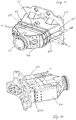
- Figs. 9a and 9b show the invention realised in a productional embodiment example.
- the coupler head housing in Figs. 9a and 9b is suitably produced by cutting and bending of steel plate for the formation of two essentially uniform parts, which are assembled into a box-shaped unit.
- the sides 6e and 6f of the coupler head may at least partly be formed by bending an originally plane or compression-moulded blank into an upper part and a bottom, respectively, with supplementing parts attached by welding.
- the upper part and the bottom may finally be united by a horizontally running welding seam.
- the coupler head according to Figs. 9a and 9b comprises a rear part, which carries an attachment 21 for a drawbar, as well as a front part, which carries a front plate 22 having a guide cone 7, as well as a seat 23 for the bearing of the shaft of the coupling mechanism.
- the front and rear parts of the coupler head housing are united by a deformation zone D 1 in the form of transverse bendings in the upper part 6c and bottom 6d, respectively, of the coupler head housing (see Fig. 9b ), which bendings form notches 11 for the axial compression of the coupler head housing by folding.
- a deformation zone D 1 in the form of transverse bendings in the upper part 6c and bottom 6d, respectively, of the coupler head housing (see Fig. 9b ), which bendings form notches 11 for the axial compression of the coupler head housing by folding.
- the side portions 61e and 61f which connect to the rear part of the coupler head housing, extend forward toward the front plate 22 and more precisely outside and partly in overlapping relationship with the side portions 62e and 62f, respectively, which connect to the front part of the coupler head housing. From the overlapping area, the side portions 62e and 62f extend divergingly up to the front plate 22.
- a side beam 24 having a U-shaped cross-section surrounds the side portions from outside and is only in a front end fixedly connected with the front part of the coupler head housing, but lacks anchorage to the rear part of the coupler head housing.
- a recess 25 is formed in the sides of the U-beam right in front of the deformation zone to allow folding and expansion of the upper part and the bottom within the deformation zone D 1.
- the side portions 61e and 61f may be connected with the upper part and the bottom only in the area outside, or behind, the deformation zone.
- a frictional force may be provided that retards the motion of the intermediately supported side portion 61e/61f.
- the side beam 24 and the side portion 62e/62f can co-operate in a mechanical joint essentially in the way described above with reference to, among others, Fig. 4 .
- the coupler head housing comprises a back piece 26 included as a part of the rear part of the coupler head housing.
- the back piece 26 may be produced, for instance, by cutting and bending and/or compression-moulding of a steel plate blank.
- an attachment is arranged for a drawbar, which attachment is in the form of a pipe sleeve 21 traversing the back piece.
- the upper part, bottom and sides of the coupler head housing extend forward to the front plate 22.
- these may be manufactured by cutting and bending and/or compression-moulding of one or more steel plate blanks, which, where appropriate, are assembled, preferably by welding.
- a circumferential deformation zone D1 is arranged in the form of transverse bendings in the upper part, bottom as well as sides of the coupler head housing, which bendings form notches 11 for the axial compression of the coupler head housing by folding. More precisely, the embodiment according to Fig. 11 comprises two or more folding zones running in parallel at which the sheet-metal plate in the upper part, the bottom and the sides is bent outward. Even if the bulgings of the embodiment example are V-shaped, it is appreciated that these nevertheless may have another shape, and for instance comprise several steps, or be continuously arc-shaped.
- connecting portions 27 run, which extend through the corner connections between the sides and the upper part and bottom, respectively, of the coupler head housing, and which delimit those slots in the corner areas that in the embodiment shown have been recessed to allow a uniform and controlled deformation of the coupler head housing.
- the sides 6e and 6f of the coupler head housing extend divergingly forward toward the front plate 22.
- the sides 6e, 6f may advantageously be made with one or more longitudinal bendings 28, which contribute to increased axial stiffness of the front part of the coupler head housing.
- the deformation zone D1 may in a meritorious way be produced by compression-moulding of a steel plate blank, which then is installed in the coupler head housing by welding.
- the shock-absorbing coupler head may advantageously be utilized in combination with other shock-absorbing means in the coupling arrangement, such as deformation tubes and/or resilient devices, known per se.
- the shock-absorbing members of the coupling arrangement are suitably adapted in such a way that all are maximally utilized before a destructive force is initiated in the car chassis.
Landscapes
- Engineering & Computer Science (AREA)
- Mechanical Engineering (AREA)
- Transportation (AREA)
- Vibration Dampers (AREA)
- Connection Of Plates (AREA)
- Body Structure For Vehicles (AREA)
Claims (20)
- Kopplungskopf (1) für eine Kopplungsanordnung, welcher Kopplungskopf ein Kopplungskopfgehäuse (6) umfasst, das sich in einer Längsrichtung von einem ersten Ende (6a), das an einer Zugstange (2) befestigbar ist, zu einem zweiten Ende (6b) erstreckt, das angeordnet ist, eine Kopplungsgrenzfläche zwischen gekoppelten Schienenfahrzeugen zu tragen, welches Kopplungskopfgehäuse mechanische Kopplungskomponenten (8, 9) aufnimmt, die für eine automatische Kopplung an die entsprechenden Komponenten einer Verbindungskopplungsanordnung wirksam sind, dadurch gekennzeichnet, dass das Kopplungskopfgehäuse mit einer Kerbe (11; 11'; 12) für eine vorbestimmte und primär axiale Kompression derselben mit Energieabsorption von einer verformenden Kompressionskraft, die an den Kopplungskopf in seiner Längsrichtung ausgeübt wird, bereitgestellt ist.
- Kopplungskopf nach Anspruch 1, welcher Kopplungskopf mindestens eine Kerbe (11; 11') für eine vorbestimmte Faltung des Kopplungskopfgehäuses hat.
- Kopplungskopf nach Anspruch 2, wobei die mindestens eine Verformungskerbe (11; 11') eine primäre Verformungszone (D1) definiert, die hinter dem Lager der mechanischen Kopplungskomponenten (8-10) im Kopplungskopfgehäuse gelegen ist.
- Kopplungskopf nach Anspruch 3, wobei eine zusätzliche Verformungskerbe (12) eine sekundäre Verformungszone (D2) definiert, die vor dem Lager der mechanischen Kopplungskomponenten (8-10) im Kopplungskopfgehäuse gelegen ist.
- Kopplungskopf nach einem der vorstehenden Ansprüche, wobei das Kopplungskopfgehäuse zwei gegenüberliegende Seiten (6e, 6f) umfasst, die mit einem oberen Teil (6c) bzw. einem Boden (6d) verbunden sind, wobei Verformungskerben (11, 11') gleichförmig mindestens im oberen Teil (6c) und Boden (6d) des Kopplungskopfgehäuses gebildet sind.
- Kopplungskopf nach Anspruch 5, wobei Verformungskerben (11) durch den oberen Teil (6c), den Boden (6d) und die Seiten (6e, 6f) eine Verformungszone (D1) bilden, die das Kopplungskopfgehäuse umgibt.
- Kopplungskopf nach Anspruch 6, wobei die Verformungszone (D1) aus einem kompressionsgeformten Stahlplattenrohling besteht, der im Kopplungskopfgehäuse durch Schweißen installiert ist.
- Kopplungskopfgehäuse nach Anspruch 6 oder 7, wobei die Seiten (6e, 6f) des Kopplungskopfgehäuses von der Verformungszone (D1) zu einer Vorderplatte (22) auseinanderlaufen, die im vorderen Ende des Kopplungskopfgehäuses getragen wird.
- Kopplungskopf nach einem der Ansprüche 5-8, wobei die Verformungskerben (11') asymmetrisch im oberen Teil (6c) bzw. Boden (6d) des Kopplungskopfgehäuses angeordnet sind.
- Kopplungskopf nach Anspruch 9, wobei die Verformungskerben (11') eine Verformungszone (D1') definieren, die zu einer Seite des Kopplungskopfgehäuses divergiert.
- Kopplungskopf nach Anspruch 9 oder 10, wobei die Verformungskerben (11; 11') gebildet sind, eine größere Kompression in der Seite (6e) des Kopplungskopfgehäuses zu erzeugen, der eine Kopplungsverbindung (9) des Kopplungsmechanismus am nächsten liegt.
- Kopplungskopf nach Anspruch 3, wobei das Kopplungskopfgehäuse zusätzlich ein Mittel umfasst, das in seine Struktur eingeführt ist und von der Verformungszone (D1) gelöst ist und das eine zusätzliche Verformungsbeständigkeit im Verlauf einer Verformung bereitstellt.
- Kopplungskopf nach Anspruch 12, wobei das Mittel in einer Seite des Kopplungskopfgehäuses in der Form einer Biegung oder durch eine Materialdicke, die lokal in der Seite variiert, gebildet ist.
- Kopplungskopf nach Anspruch 12, wobei das Mittel wechselseitig gelöste Teile (61e, 62e; 61f, 62f) der Seite des Kopplungskopfgehäuses umfasst, die einzeln mit dem Kopplungskopfgehäuse verbunden sind, aber wechselseitig beweglich sind und bei wechselseitiger Verschiebung eine Biegung mindestens eines der Teile (61e, 61f) der Seite bewirken.
- Kopplungskopf nach Anspruch 12, wobei das Mittel angeordnet ist, um eine Reibungsbeständigkeit bereitzustellen, während eine Vorspannungskraft überwunden wird, die zwischen wechselseitig beweglichen verbundenen Teilen (61e, 62e; 61f, 62f) der Seite des Kopplungskopfgehäuses wirkt.
- Kopplungskopf nach Anspruch 15, wobei das Kopplungskopfgehäuse in mindestens einer Seite (6e, 6f) einen ersten Seitenabschnitt (61e, 61f) hat, der unter Vorspannung durch Klemmen gegen einen überlappenden Bereich eines zweiten Seitenabschnitts (62e, 62f) der Seite (6e, 6f) des Kopplungskopfgehäuses fixiert ist.
- Kopplungskopf nach Anspruch 16, wobei die Seitenabschnitte (61e, 62e; 61f, 62f) im überlappenden Bereich durch eine kontrollierte festziehbare Verschraubung (14, 15, 16) miteinander verbunden sind.
- Kopplungskopf nach Anspruch 16 oder 17, wobei ein reibungserhöhendes Mittel (20) zwischen den Seitenabschnitten (61e, 62e; 61f, 62f) im überlappenden Bereich eingeführt ist.
- Kopplungskopf nach Anspruch 11, wobei das Kopplungskopfgehäuse, durch einen asymmetrischen Kompressionsverlauf, angeordnet ist, eine Verrieglung der mechanischen Kopplungskomponenten (8, 9) im gekoppelten Zustand bereitzustellen, indem eine zentrale Platte (8) mit der Seite (6f) des Kopplungskopfgehäuses in Eingriff gebracht wird.
- Kopplungskopf nach einem der vorstehenden Ansprüche, der eine Verformungskerbe (11, 11', 12) hat, die durch eine relative Schwachstelle, die lokal im Kopplungskopfgehäuse angebracht wird, gebildet ist und umfassend eine oder mehrere der Maßnahmen Kompressionsformen, Biegen, Fräsen, Lochbildung, unterschiedliche Materialdicke, lokale Verhärtung, Kombination oder Kombinationen verschiedener Materialien, Materialzusammensetzung oder Hinzufügen von Material.
Priority Applications (1)
| Application Number | Priority Date | Filing Date | Title |
|---|---|---|---|
| PL11798446T PL2585352T3 (pl) | 2010-06-23 | 2011-06-08 | Pochłaniająca wstrząsy głowica haka cięgłowego dla układu sprzęgowego |
Applications Claiming Priority (2)
| Application Number | Priority Date | Filing Date | Title |
|---|---|---|---|
| SE1050678A SE534926C2 (sv) | 2010-06-23 | 2010-06-23 | Energiupptagande koppelhuvud för en draginrättning |
| PCT/SE2011/050706 WO2011162674A1 (en) | 2010-06-23 | 2011-06-08 | Shock-absorbing coupler head for a coupling arrangement |
Publications (3)
| Publication Number | Publication Date |
|---|---|
| EP2585352A1 EP2585352A1 (de) | 2013-05-01 |
| EP2585352A4 EP2585352A4 (de) | 2018-02-28 |
| EP2585352B1 true EP2585352B1 (de) | 2019-08-07 |
Family
ID=45371652
Family Applications (1)
| Application Number | Title | Priority Date | Filing Date |
|---|---|---|---|
| EP11798446.8A Active EP2585352B1 (de) | 2010-06-23 | 2011-06-08 | Stossdämpfender kopplungskopf für eine kopplungsanordnung |
Country Status (10)
| Country | Link |
|---|---|
| US (1) | US8915385B2 (de) |
| EP (1) | EP2585352B1 (de) |
| CN (1) | CN103003128B (de) |
| BR (1) | BR112012032937A2 (de) |
| CA (1) | CA2803301C (de) |
| ES (1) | ES2748515T3 (de) |
| PL (1) | PL2585352T3 (de) |
| RU (1) | RU2563078C2 (de) |
| SE (1) | SE534926C2 (de) |
| WO (1) | WO2011162674A1 (de) |
Families Citing this family (13)
| Publication number | Priority date | Publication date | Assignee | Title |
|---|---|---|---|---|
| SE535190C2 (sv) * | 2010-09-14 | 2012-05-15 | Ego Int Bv | Mekanisk koppling för en draginrättning |
| KR101381384B1 (ko) | 2012-10-24 | 2014-04-15 | 유진기공산업주식회사 | 철도 차량용 연결기 |
| FR3014514B1 (fr) * | 2013-12-09 | 2016-01-15 | Alstom Transp Tech | Dispositif d'amortissement, notamment pour un dispositif d'attelage de vehicule ferroviaire |
| DE102015204008A1 (de) * | 2015-03-05 | 2016-09-08 | Bombardier Transportation Gmbh | Drehgelenk zum drehgelenkigen Verbinden von Schienenfahrzeugen |
| US9701323B2 (en) | 2015-04-06 | 2017-07-11 | Bedloe Industries Llc | Railcar coupler |
| CN108556868B (zh) * | 2018-01-26 | 2020-04-10 | 连江县维佳工业设计有限公司 | 一种火车车厢用可拆挂钩机构 |
| CN108556867B (zh) * | 2018-01-26 | 2020-04-24 | 刘晓冰 | 一种基于齿轮传动的用于车厢连接的可拆挂钩机构 |
| AT522658A1 (de) | 2019-05-20 | 2020-12-15 | Siemens Mobility Austria Gmbh | Energieverzehreinrichtung |
| EP3992054B1 (de) * | 2019-09-09 | 2023-07-19 | Crrc Qingdao Sifang Rolling Stock Research Institute Co., Ltd. | Faltbare fahrzeugkupplung und fahrzeug |
| DE102021107936A1 (de) | 2021-03-30 | 2022-10-06 | Knorr-Bremse Systeme für Schienenfahrzeuge GmbH | Automatische Mittelpufferkupplung für Schienenfahrzeuge sowie hieraus zusammengesetzte Kupplungsanordnung |
| SE545564C2 (en) * | 2022-03-03 | 2023-10-24 | Dellner Couplers Ab | Coupler for a railway vehicle with a biasing device, and method for overhauling a coupler |
| CN114889668B (zh) * | 2022-06-28 | 2023-08-01 | 中车制动系统有限公司 | 浮动式电气车钩推送机构及具有其的车钩 |
| EP4371848B1 (de) * | 2022-11-16 | 2025-05-14 | Dellner Couplers AB | Kopplerkopfvorderseite |
Family Cites Families (19)
| Publication number | Priority date | Publication date | Assignee | Title |
|---|---|---|---|---|
| US1585420A (en) * | 1924-05-14 | 1926-05-18 | Scharfenberg Karl | Railway-car coupling |
| BE420381A (de) * | 1936-03-10 | |||
| NL258873A (de) * | 1959-12-11 | |||
| FI56509C (fi) * | 1972-12-13 | 1980-02-11 | Franco Belge Mat Chemin Fer | Automatisk koppling |
| SU662396A1 (ru) * | 1977-11-18 | 1979-05-15 | Ждановский металлургический институт | Противоаварийное буферное устройство |
| DE3228941A1 (de) * | 1982-08-03 | 1984-02-09 | Scharfenbergkupplung Gmbh, 3320 Salzgitter | Einer mittelpufferkupplung nachgeschaltete vorrichtung zur aufnahme uebergrosser stoesse |
| DE19833250C2 (de) * | 1998-07-23 | 2002-11-07 | Siemens Ag | Energieverzehrelement für Schienenfahrzeuge und Verfahren zur Herstellung eines Energieverzehrelements |
| US6499613B1 (en) * | 1999-12-30 | 2002-12-31 | Westinghouse Air Brake Company | Coupler with extended emergency release and towing feature |
| EP1312527B1 (de) | 2001-09-17 | 2003-06-04 | Voith Turbo Scharfenberg GmbH & Co. KG | Gelenkanordnung |
| SE526056C2 (sv) * | 2003-09-10 | 2005-06-21 | Dellner Couplers Ab | Krockskydd för rälsfordonskopplingar samt en med ett dylikt krockskydd utförd länkanordning för permanent hopkoppling av två rälsfordonsenheter |
| DE502004007562D1 (de) * | 2004-09-06 | 2008-08-21 | Voith Turbo Scharfenberg Gmbh | Kupplungskopf mit lösbarer Stirnplatte, für Schienenfahrzeuge, sowie dazugehöriges Montageverfahren |
| DE102004045737B4 (de) * | 2004-09-21 | 2015-07-16 | Sieghard Schneider | Deformierbare Pufferkonsole mit innenliegender Führung und Auslösung |
| AT501689A1 (de) * | 2005-04-04 | 2006-10-15 | Siemens Transportation Systems | Schienenfahrzeug mit kollisionstauglicher kupplungsanbindung |
| DE502006004531D1 (de) * | 2006-10-19 | 2009-09-24 | Voith Turbo Scharfenberg Gmbh | Energieverzehrvorrichtung für mehrgliedrige Fahrzeuge |
| RU63763U1 (ru) * | 2006-12-22 | 2007-06-10 | Илья Геронтьевич Морчиладзе | Регулируемое сцепное устройство вагона |
| PT1955918E (pt) * | 2007-02-08 | 2009-07-16 | Voith Patent Gmbh | Engate central automático de amortecimento |
| SE534923C2 (sv) * | 2010-06-23 | 2012-02-21 | Ego Int Bv | Draginrättning med en genom ett koppelhuvud gående förstyvningsbalk |
| SE534925C2 (sv) * | 2010-06-23 | 2012-02-21 | Ego Int Bv | Energiupptagande draginrättning |
| SE534924C2 (sv) * | 2010-06-23 | 2012-02-21 | Ego Int Bv | Draginrättning med organ för knäckstyv förbindning av kopplade rälsfordon vid kollision |
-
2010
- 2010-06-23 SE SE1050678A patent/SE534926C2/sv not_active IP Right Cessation
-
2011
- 2011-06-08 CN CN201180031299.1A patent/CN103003128B/zh not_active Expired - Fee Related
- 2011-06-08 RU RU2013102425/11A patent/RU2563078C2/ru not_active IP Right Cessation
- 2011-06-08 ES ES11798446T patent/ES2748515T3/es active Active
- 2011-06-08 PL PL11798446T patent/PL2585352T3/pl unknown
- 2011-06-08 US US13/805,537 patent/US8915385B2/en active Active
- 2011-06-08 EP EP11798446.8A patent/EP2585352B1/de active Active
- 2011-06-08 CA CA2803301A patent/CA2803301C/en not_active Expired - Fee Related
- 2011-06-08 WO PCT/SE2011/050706 patent/WO2011162674A1/en not_active Ceased
- 2011-06-08 BR BR112012032937A patent/BR112012032937A2/pt not_active IP Right Cessation
Non-Patent Citations (1)
| Title |
|---|
| None * |
Also Published As
| Publication number | Publication date |
|---|---|
| SE1050678A1 (sv) | 2011-12-24 |
| EP2585352A1 (de) | 2013-05-01 |
| PL2585352T3 (pl) | 2020-01-31 |
| CA2803301C (en) | 2018-09-11 |
| RU2563078C2 (ru) | 2015-09-20 |
| CA2803301A1 (en) | 2011-12-29 |
| ES2748515T3 (es) | 2020-03-17 |
| US20130105431A1 (en) | 2013-05-02 |
| WO2011162674A1 (en) | 2011-12-29 |
| BR112012032937A2 (pt) | 2016-11-22 |
| US8915385B2 (en) | 2014-12-23 |
| RU2013102425A (ru) | 2014-07-27 |
| CN103003128B (zh) | 2016-03-30 |
| CN103003128A (zh) | 2013-03-27 |
| EP2585352A4 (de) | 2018-02-28 |
| SE534926C2 (sv) | 2012-02-21 |
Similar Documents
| Publication | Publication Date | Title |
|---|---|---|
| EP2585352B1 (de) | Stossdämpfender kopplungskopf für eine kopplungsanordnung | |
| RU2559870C2 (ru) | Сцепной узел для соединения железнодорожных вагонов | |
| CN100400352C (zh) | 铁道车辆连接中的牵引装置和变形管 | |
| AU2008297116B2 (en) | Shock absorber | |
| AU2009200720B2 (en) | Supporting device to vertically support a coupling rod as well as use of the supporting device in a railborne vehicle | |
| EP1247716B1 (de) | Zweistufiger Puffer | |
| CN112533815B (zh) | 具有轴向伸展模块的车钩装置 | |
| CN105151075A (zh) | 一种吸能装置及具有该吸能装置的轨道车辆 | |
| CN113844544A (zh) | 用于管理前部碰撞事件中的横向载荷的车辆结构 | |
| WO2004111485A2 (en) | Friction damper | |
| CN113844542A (zh) | 用于小重叠碰撞的轮偏转器 | |
| US20050145591A1 (en) | Center buffer coupling for railroad cars | |
| CN113844543B (zh) | 用于管理前部碰撞事件中的横向载荷的车辆结构 | |
| CN110816579B (zh) | 一种轨道车辆吸能防爬装置 | |
| CN113844222A (zh) | 用于小重叠碰撞的下控制臂机构 | |
| EP2585351B1 (de) | Knickfeste kopplungsanordnung für schienenfahrzeuge | |
| CN100439174C (zh) | 用于0.625米(24.625英寸)凹穴的长缓冲短牵引行程的牵引装置 | |
| WO2011162671A1 (en) | Shock-absorbing coupling arrangement | |
| KR102141113B1 (ko) | 철도차량 연결기용 충격흡수장치 | |
| WO2016156793A1 (en) | An energy absorption assembly | |
| US20070205066A1 (en) | Multimodular multistage high impact collision energy absorber | |
| JP4785046B2 (ja) | 鉄道車両用連結装置 | |
| CN119319820B (zh) | 一种具有吸能结构的前副车架 | |
| CN119749620B (zh) | 一种径向变形式防爬吸能装置 | |
| SE542355C2 (en) | Train coupler arrangement with axial expansion module |
Legal Events
| Date | Code | Title | Description |
|---|---|---|---|
| PUAI | Public reference made under article 153(3) epc to a published international application that has entered the european phase |
Free format text: ORIGINAL CODE: 0009012 |
|
| 17P | Request for examination filed |
Effective date: 20121220 |
|
| AK | Designated contracting states |
Kind code of ref document: A1 Designated state(s): AL AT BE BG CH CY CZ DE DK EE ES FI FR GB GR HR HU IE IS IT LI LT LU LV MC MK MT NL NO PL PT RO RS SE SI SK SM TR |
|
| DAX | Request for extension of the european patent (deleted) | ||
| RA4 | Supplementary search report drawn up and despatched (corrected) |
Effective date: 20180129 |
|
| RIC1 | Information provided on ipc code assigned before grant |
Ipc: B61G 11/16 20060101ALI20180123BHEP Ipc: B61D 15/06 20060101ALI20180123BHEP Ipc: B61G 7/14 20060101AFI20180123BHEP Ipc: B61G 3/16 20060101ALI20180123BHEP |
|
| GRAP | Despatch of communication of intention to grant a patent |
Free format text: ORIGINAL CODE: EPIDOSNIGR1 |
|
| STAA | Information on the status of an ep patent application or granted ep patent |
Free format text: STATUS: GRANT OF PATENT IS INTENDED |
|
| INTG | Intention to grant announced |
Effective date: 20190305 |
|
| RAP1 | Party data changed (applicant data changed or rights of an application transferred) |
Owner name: DELLNER COUPLERS AB |
|
| GRAS | Grant fee paid |
Free format text: ORIGINAL CODE: EPIDOSNIGR3 |
|
| GRAA | (expected) grant |
Free format text: ORIGINAL CODE: 0009210 |
|
| STAA | Information on the status of an ep patent application or granted ep patent |
Free format text: STATUS: THE PATENT HAS BEEN GRANTED |
|
| AK | Designated contracting states |
Kind code of ref document: B1 Designated state(s): AL AT BE BG CH CY CZ DE DK EE ES FI FR GB GR HR HU IE IS IT LI LT LU LV MC MK MT NL NO PL PT RO RS SE SI SK SM TR |
|
| REG | Reference to a national code |
Ref country code: GB Ref legal event code: FG4D |
|
| REG | Reference to a national code |
Ref country code: CH Ref legal event code: EP Ref country code: AT Ref legal event code: REF Ref document number: 1163403 Country of ref document: AT Kind code of ref document: T Effective date: 20190815 |
|
| REG | Reference to a national code |
Ref country code: DE Ref legal event code: R096 Ref document number: 602011061109 Country of ref document: DE |
|
| REG | Reference to a national code |
Ref country code: IE Ref legal event code: FG4D |
|
| REG | Reference to a national code |
Ref country code: SE Ref legal event code: TRGR |
|
| REG | Reference to a national code |
Ref country code: NL Ref legal event code: MP Effective date: 20190807 |
|
| REG | Reference to a national code |
Ref country code: LT Ref legal event code: MG4D |
|
| PG25 | Lapsed in a contracting state [announced via postgrant information from national office to epo] |
Ref country code: NO Free format text: LAPSE BECAUSE OF FAILURE TO SUBMIT A TRANSLATION OF THE DESCRIPTION OR TO PAY THE FEE WITHIN THE PRESCRIBED TIME-LIMIT Effective date: 20191107 Ref country code: PT Free format text: LAPSE BECAUSE OF FAILURE TO SUBMIT A TRANSLATION OF THE DESCRIPTION OR TO PAY THE FEE WITHIN THE PRESCRIBED TIME-LIMIT Effective date: 20191209 Ref country code: LT Free format text: LAPSE BECAUSE OF FAILURE TO SUBMIT A TRANSLATION OF THE DESCRIPTION OR TO PAY THE FEE WITHIN THE PRESCRIBED TIME-LIMIT Effective date: 20190807 Ref country code: BG Free format text: LAPSE BECAUSE OF FAILURE TO SUBMIT A TRANSLATION OF THE DESCRIPTION OR TO PAY THE FEE WITHIN THE PRESCRIBED TIME-LIMIT Effective date: 20191107 Ref country code: NL Free format text: LAPSE BECAUSE OF FAILURE TO SUBMIT A TRANSLATION OF THE DESCRIPTION OR TO PAY THE FEE WITHIN THE PRESCRIBED TIME-LIMIT Effective date: 20190807 Ref country code: FI Free format text: LAPSE BECAUSE OF FAILURE TO SUBMIT A TRANSLATION OF THE DESCRIPTION OR TO PAY THE FEE WITHIN THE PRESCRIBED TIME-LIMIT Effective date: 20190807 Ref country code: HR Free format text: LAPSE BECAUSE OF FAILURE TO SUBMIT A TRANSLATION OF THE DESCRIPTION OR TO PAY THE FEE WITHIN THE PRESCRIBED TIME-LIMIT Effective date: 20190807 |
|
| REG | Reference to a national code |
Ref country code: AT Ref legal event code: MK05 Ref document number: 1163403 Country of ref document: AT Kind code of ref document: T Effective date: 20190807 |
|
| PG25 | Lapsed in a contracting state [announced via postgrant information from national office to epo] |
Ref country code: AL Free format text: LAPSE BECAUSE OF FAILURE TO SUBMIT A TRANSLATION OF THE DESCRIPTION OR TO PAY THE FEE WITHIN THE PRESCRIBED TIME-LIMIT Effective date: 20190807 Ref country code: GR Free format text: LAPSE BECAUSE OF FAILURE TO SUBMIT A TRANSLATION OF THE DESCRIPTION OR TO PAY THE FEE WITHIN THE PRESCRIBED TIME-LIMIT Effective date: 20191108 Ref country code: IS Free format text: LAPSE BECAUSE OF FAILURE TO SUBMIT A TRANSLATION OF THE DESCRIPTION OR TO PAY THE FEE WITHIN THE PRESCRIBED TIME-LIMIT Effective date: 20191207 Ref country code: RS Free format text: LAPSE BECAUSE OF FAILURE TO SUBMIT A TRANSLATION OF THE DESCRIPTION OR TO PAY THE FEE WITHIN THE PRESCRIBED TIME-LIMIT Effective date: 20190807 Ref country code: LV Free format text: LAPSE BECAUSE OF FAILURE TO SUBMIT A TRANSLATION OF THE DESCRIPTION OR TO PAY THE FEE WITHIN THE PRESCRIBED TIME-LIMIT Effective date: 20190807 |
|
| REG | Reference to a national code |
Ref country code: ES Ref legal event code: FG2A Ref document number: 2748515 Country of ref document: ES Kind code of ref document: T3 Effective date: 20200317 |
|
| PG25 | Lapsed in a contracting state [announced via postgrant information from national office to epo] |
Ref country code: TR Free format text: LAPSE BECAUSE OF FAILURE TO SUBMIT A TRANSLATION OF THE DESCRIPTION OR TO PAY THE FEE WITHIN THE PRESCRIBED TIME-LIMIT Effective date: 20190807 |
|
| PG25 | Lapsed in a contracting state [announced via postgrant information from national office to epo] |
Ref country code: IT Free format text: LAPSE BECAUSE OF FAILURE TO SUBMIT A TRANSLATION OF THE DESCRIPTION OR TO PAY THE FEE WITHIN THE PRESCRIBED TIME-LIMIT Effective date: 20190807 Ref country code: AT Free format text: LAPSE BECAUSE OF FAILURE TO SUBMIT A TRANSLATION OF THE DESCRIPTION OR TO PAY THE FEE WITHIN THE PRESCRIBED TIME-LIMIT Effective date: 20190807 Ref country code: DK Free format text: LAPSE BECAUSE OF FAILURE TO SUBMIT A TRANSLATION OF THE DESCRIPTION OR TO PAY THE FEE WITHIN THE PRESCRIBED TIME-LIMIT Effective date: 20190807 Ref country code: EE Free format text: LAPSE BECAUSE OF FAILURE TO SUBMIT A TRANSLATION OF THE DESCRIPTION OR TO PAY THE FEE WITHIN THE PRESCRIBED TIME-LIMIT Effective date: 20190807 Ref country code: RO Free format text: LAPSE BECAUSE OF FAILURE TO SUBMIT A TRANSLATION OF THE DESCRIPTION OR TO PAY THE FEE WITHIN THE PRESCRIBED TIME-LIMIT Effective date: 20190807 |
|
| PG25 | Lapsed in a contracting state [announced via postgrant information from national office to epo] |
Ref country code: SK Free format text: LAPSE BECAUSE OF FAILURE TO SUBMIT A TRANSLATION OF THE DESCRIPTION OR TO PAY THE FEE WITHIN THE PRESCRIBED TIME-LIMIT Effective date: 20190807 Ref country code: CZ Free format text: LAPSE BECAUSE OF FAILURE TO SUBMIT A TRANSLATION OF THE DESCRIPTION OR TO PAY THE FEE WITHIN THE PRESCRIBED TIME-LIMIT Effective date: 20190807 Ref country code: SM Free format text: LAPSE BECAUSE OF FAILURE TO SUBMIT A TRANSLATION OF THE DESCRIPTION OR TO PAY THE FEE WITHIN THE PRESCRIBED TIME-LIMIT Effective date: 20190807 Ref country code: IS Free format text: LAPSE BECAUSE OF FAILURE TO SUBMIT A TRANSLATION OF THE DESCRIPTION OR TO PAY THE FEE WITHIN THE PRESCRIBED TIME-LIMIT Effective date: 20200224 |
|
| REG | Reference to a national code |
Ref country code: DE Ref legal event code: R097 Ref document number: 602011061109 Country of ref document: DE |
|
| PLBE | No opposition filed within time limit |
Free format text: ORIGINAL CODE: 0009261 |
|
| STAA | Information on the status of an ep patent application or granted ep patent |
Free format text: STATUS: NO OPPOSITION FILED WITHIN TIME LIMIT |
|
| PG2D | Information on lapse in contracting state deleted |
Ref country code: IS |
|
| 26N | No opposition filed |
Effective date: 20200603 |
|
| PG25 | Lapsed in a contracting state [announced via postgrant information from national office to epo] |
Ref country code: SI Free format text: LAPSE BECAUSE OF FAILURE TO SUBMIT A TRANSLATION OF THE DESCRIPTION OR TO PAY THE FEE WITHIN THE PRESCRIBED TIME-LIMIT Effective date: 20190807 |
|
| PG25 | Lapsed in a contracting state [announced via postgrant information from national office to epo] |
Ref country code: MC Free format text: LAPSE BECAUSE OF FAILURE TO SUBMIT A TRANSLATION OF THE DESCRIPTION OR TO PAY THE FEE WITHIN THE PRESCRIBED TIME-LIMIT Effective date: 20190807 |
|
| REG | Reference to a national code |
Ref country code: CH Ref legal event code: PL |
|
| GBPC | Gb: european patent ceased through non-payment of renewal fee |
Effective date: 20200608 |
|
| PG25 | Lapsed in a contracting state [announced via postgrant information from national office to epo] |
Ref country code: LU Free format text: LAPSE BECAUSE OF NON-PAYMENT OF DUE FEES Effective date: 20200608 |
|
| REG | Reference to a national code |
Ref country code: BE Ref legal event code: MM Effective date: 20200630 |
|
| PG25 | Lapsed in a contracting state [announced via postgrant information from national office to epo] |
Ref country code: CH Free format text: LAPSE BECAUSE OF NON-PAYMENT OF DUE FEES Effective date: 20200630 Ref country code: IE Free format text: LAPSE BECAUSE OF NON-PAYMENT OF DUE FEES Effective date: 20200608 Ref country code: LI Free format text: LAPSE BECAUSE OF NON-PAYMENT OF DUE FEES Effective date: 20200630 Ref country code: GB Free format text: LAPSE BECAUSE OF NON-PAYMENT OF DUE FEES Effective date: 20200608 Ref country code: FR Free format text: LAPSE BECAUSE OF NON-PAYMENT OF DUE FEES Effective date: 20200630 |
|
| PG25 | Lapsed in a contracting state [announced via postgrant information from national office to epo] |
Ref country code: BE Free format text: LAPSE BECAUSE OF NON-PAYMENT OF DUE FEES Effective date: 20200630 Ref country code: SE Free format text: LAPSE BECAUSE OF NON-PAYMENT OF DUE FEES Effective date: 20200609 |
|
| REG | Reference to a national code |
Ref country code: SE Ref legal event code: EUG |
|
| REG | Reference to a national code |
Ref country code: ES Ref legal event code: FD2A Effective date: 20211027 |
|
| PG25 | Lapsed in a contracting state [announced via postgrant information from national office to epo] |
Ref country code: ES Free format text: LAPSE BECAUSE OF NON-PAYMENT OF DUE FEES Effective date: 20200609 |
|
| PG25 | Lapsed in a contracting state [announced via postgrant information from national office to epo] |
Ref country code: MT Free format text: LAPSE BECAUSE OF FAILURE TO SUBMIT A TRANSLATION OF THE DESCRIPTION OR TO PAY THE FEE WITHIN THE PRESCRIBED TIME-LIMIT Effective date: 20190807 Ref country code: CY Free format text: LAPSE BECAUSE OF FAILURE TO SUBMIT A TRANSLATION OF THE DESCRIPTION OR TO PAY THE FEE WITHIN THE PRESCRIBED TIME-LIMIT Effective date: 20190807 |
|
| PG25 | Lapsed in a contracting state [announced via postgrant information from national office to epo] |
Ref country code: MK Free format text: LAPSE BECAUSE OF FAILURE TO SUBMIT A TRANSLATION OF THE DESCRIPTION OR TO PAY THE FEE WITHIN THE PRESCRIBED TIME-LIMIT Effective date: 20190807 |
|
| PG25 | Lapsed in a contracting state [announced via postgrant information from national office to epo] |
Ref country code: PL Free format text: LAPSE BECAUSE OF NON-PAYMENT OF DUE FEES Effective date: 20200608 |
|
| PGFP | Annual fee paid to national office [announced via postgrant information from national office to epo] |
Ref country code: DE Payment date: 20240612 Year of fee payment: 14 |
|
| REG | Reference to a national code |
Ref country code: DE Ref legal event code: R119 Ref document number: 602011061109 Country of ref document: DE |
|
| PG25 | Lapsed in a contracting state [announced via postgrant information from national office to epo] |
Ref country code: DE Free format text: LAPSE BECAUSE OF NON-PAYMENT OF DUE FEES Effective date: 20260101 |