EP2584827B1 - Terminal apparatus and communication method thereof - Google Patents
Terminal apparatus and communication method thereof Download PDFInfo
- Publication number
- EP2584827B1 EP2584827B1 EP11797776.9A EP11797776A EP2584827B1 EP 2584827 B1 EP2584827 B1 EP 2584827B1 EP 11797776 A EP11797776 A EP 11797776A EP 2584827 B1 EP2584827 B1 EP 2584827B1
- Authority
- EP
- European Patent Office
- Prior art keywords
- pusch
- initial
- control information
- resource
- amount
- Prior art date
- Legal status (The legal status is an assumption and is not a legal conclusion. Google has not performed a legal analysis and makes no representation as to the accuracy of the status listed.)
- Active
Links
- 238000000034 method Methods 0.000 title claims description 72
- 238000004891 communication Methods 0.000 title description 10
- 230000005540 biological transmission Effects 0.000 claims description 194
- 238000012937 correction Methods 0.000 claims description 95
- 101000741965 Homo sapiens Inactive tyrosine-protein kinase PRAG1 Proteins 0.000 claims description 86
- 102100038659 Inactive tyrosine-protein kinase PRAG1 Human genes 0.000 claims description 86
- 239000000284 extract Substances 0.000 claims description 4
- 239000010410 layer Substances 0.000 description 230
- 102100036409 Activated CDC42 kinase 1 Human genes 0.000 description 83
- 238000012545 processing Methods 0.000 description 45
- 230000011664 signaling Effects 0.000 description 19
- 230000015556 catabolic process Effects 0.000 description 13
- 238000006731 degradation reaction Methods 0.000 description 13
- 230000007423 decrease Effects 0.000 description 12
- 239000011229 interlayer Substances 0.000 description 10
- 230000009467 reduction Effects 0.000 description 7
- 238000010586 diagram Methods 0.000 description 6
- 238000004364 calculation method Methods 0.000 description 5
- 238000006243 chemical reaction Methods 0.000 description 5
- 239000011159 matrix material Substances 0.000 description 5
- 238000013468 resource allocation Methods 0.000 description 5
- 238000005516 engineering process Methods 0.000 description 4
- 238000004519 manufacturing process Methods 0.000 description 3
- 230000004044 response Effects 0.000 description 3
- 239000002356 single layer Substances 0.000 description 3
- 239000000969 carrier Substances 0.000 description 2
- 230000008859 change Effects 0.000 description 2
- 125000004122 cyclic group Chemical group 0.000 description 2
- 230000003247 decreasing effect Effects 0.000 description 2
- 230000001419 dependent effect Effects 0.000 description 2
- 102100027715 4-hydroxy-2-oxoglutarate aldolase, mitochondrial Human genes 0.000 description 1
- 101001081225 Homo sapiens 4-hydroxy-2-oxoglutarate aldolase, mitochondrial Proteins 0.000 description 1
- 101001109518 Homo sapiens N-acetylneuraminate lyase Proteins 0.000 description 1
- 102100022686 N-acetylneuraminate lyase Human genes 0.000 description 1
- 229920006934 PMI Polymers 0.000 description 1
- 102100035362 Phosphomannomutase 2 Human genes 0.000 description 1
- 238000003491 array Methods 0.000 description 1
- 230000001934 delay Effects 0.000 description 1
- 238000001514 detection method Methods 0.000 description 1
- 230000000694 effects Effects 0.000 description 1
- GVVPGTZRZFNKDS-JXMROGBWSA-N geranyl diphosphate Chemical compound CC(C)=CCC\C(C)=C\CO[P@](O)(=O)OP(O)(O)=O GVVPGTZRZFNKDS-JXMROGBWSA-N 0.000 description 1
- 230000006872 improvement Effects 0.000 description 1
- 230000010354 integration Effects 0.000 description 1
- 230000007774 longterm Effects 0.000 description 1
- 238000013507 mapping Methods 0.000 description 1
- 238000005259 measurement Methods 0.000 description 1
- 238000010295 mobile communication Methods 0.000 description 1
- 230000008569 process Effects 0.000 description 1
- 239000004065 semiconductor Substances 0.000 description 1
- 238000000926 separation method Methods 0.000 description 1
- 238000004260 weight control Methods 0.000 description 1
Images


Classifications
-
- H—ELECTRICITY
- H04—ELECTRIC COMMUNICATION TECHNIQUE
- H04W—WIRELESS COMMUNICATION NETWORKS
- H04W28/00—Network traffic management; Network resource management
- H04W28/02—Traffic management, e.g. flow control or congestion control
- H04W28/06—Optimizing the usage of the radio link, e.g. header compression, information sizing, discarding information
-
- H—ELECTRICITY
- H04—ELECTRIC COMMUNICATION TECHNIQUE
- H04L—TRANSMISSION OF DIGITAL INFORMATION, e.g. TELEGRAPHIC COMMUNICATION
- H04L5/00—Arrangements affording multiple use of the transmission path
- H04L5/003—Arrangements for allocating sub-channels of the transmission path
- H04L5/0053—Allocation of signaling, i.e. of overhead other than pilot signals
-
- H—ELECTRICITY
- H04—ELECTRIC COMMUNICATION TECHNIQUE
- H04B—TRANSMISSION
- H04B7/00—Radio transmission systems, i.e. using radiation field
- H04B7/02—Diversity systems; Multi-antenna system, i.e. transmission or reception using multiple antennas
- H04B7/04—Diversity systems; Multi-antenna system, i.e. transmission or reception using multiple antennas using two or more spaced independent antennas
- H04B7/0413—MIMO systems
- H04B7/0452—Multi-user MIMO systems
-
- H—ELECTRICITY
- H04—ELECTRIC COMMUNICATION TECHNIQUE
- H04B—TRANSMISSION
- H04B7/00—Radio transmission systems, i.e. using radiation field
- H04B7/02—Diversity systems; Multi-antenna system, i.e. transmission or reception using multiple antennas
- H04B7/04—Diversity systems; Multi-antenna system, i.e. transmission or reception using multiple antennas using two or more spaced independent antennas
- H04B7/06—Diversity systems; Multi-antenna system, i.e. transmission or reception using multiple antennas using two or more spaced independent antennas at the transmitting station
- H04B7/0613—Diversity systems; Multi-antenna system, i.e. transmission or reception using multiple antennas using two or more spaced independent antennas at the transmitting station using simultaneous transmission
- H04B7/0615—Diversity systems; Multi-antenna system, i.e. transmission or reception using multiple antennas using two or more spaced independent antennas at the transmitting station using simultaneous transmission of weighted versions of same signal
- H04B7/0619—Diversity systems; Multi-antenna system, i.e. transmission or reception using multiple antennas using two or more spaced independent antennas at the transmitting station using simultaneous transmission of weighted versions of same signal using feedback from receiving side
- H04B7/0621—Feedback content
- H04B7/0623—Auxiliary parameters, e.g. power control [PCB] or not acknowledged commands [NACK], used as feedback information
-
- H—ELECTRICITY
- H04—ELECTRIC COMMUNICATION TECHNIQUE
- H04J—MULTIPLEX COMMUNICATION
- H04J11/00—Orthogonal multiplex systems, e.g. using WALSH codes
-
- H—ELECTRICITY
- H04—ELECTRIC COMMUNICATION TECHNIQUE
- H04L—TRANSMISSION OF DIGITAL INFORMATION, e.g. TELEGRAPHIC COMMUNICATION
- H04L1/00—Arrangements for detecting or preventing errors in the information received
- H04L1/12—Arrangements for detecting or preventing errors in the information received by using return channel
- H04L1/16—Arrangements for detecting or preventing errors in the information received by using return channel in which the return channel carries supervisory signals, e.g. repetition request signals
- H04L1/1607—Details of the supervisory signal
- H04L1/1671—Details of the supervisory signal the supervisory signal being transmitted together with control information
-
- H—ELECTRICITY
- H04—ELECTRIC COMMUNICATION TECHNIQUE
- H04L—TRANSMISSION OF DIGITAL INFORMATION, e.g. TELEGRAPHIC COMMUNICATION
- H04L1/00—Arrangements for detecting or preventing errors in the information received
- H04L1/12—Arrangements for detecting or preventing errors in the information received by using return channel
- H04L1/16—Arrangements for detecting or preventing errors in the information received by using return channel in which the return channel carries supervisory signals, e.g. repetition request signals
- H04L1/18—Automatic repetition systems, e.g. Van Duuren systems
- H04L1/1829—Arrangements specially adapted for the receiver end
- H04L1/1861—Physical mapping arrangements
-
- H—ELECTRICITY
- H04—ELECTRIC COMMUNICATION TECHNIQUE
- H04L—TRANSMISSION OF DIGITAL INFORMATION, e.g. TELEGRAPHIC COMMUNICATION
- H04L27/00—Modulated-carrier systems
- H04L27/26—Systems using multi-frequency codes
- H04L27/2601—Multicarrier modulation systems
- H04L27/2626—Arrangements specific to the transmitter only
- H04L27/2627—Modulators
- H04L27/2634—Inverse fast Fourier transform [IFFT] or inverse discrete Fourier transform [IDFT] modulators in combination with other circuits for modulation
- H04L27/2636—Inverse fast Fourier transform [IFFT] or inverse discrete Fourier transform [IDFT] modulators in combination with other circuits for modulation with FFT or DFT modulators, e.g. standard single-carrier frequency-division multiple access [SC-FDMA] transmitter or DFT spread orthogonal frequency division multiplexing [DFT-SOFDM]
-
- H—ELECTRICITY
- H04—ELECTRIC COMMUNICATION TECHNIQUE
- H04L—TRANSMISSION OF DIGITAL INFORMATION, e.g. TELEGRAPHIC COMMUNICATION
- H04L5/00—Arrangements affording multiple use of the transmission path
- H04L5/0001—Arrangements for dividing the transmission path
- H04L5/0014—Three-dimensional division
- H04L5/0023—Time-frequency-space
-
- H—ELECTRICITY
- H04—ELECTRIC COMMUNICATION TECHNIQUE
- H04L—TRANSMISSION OF DIGITAL INFORMATION, e.g. TELEGRAPHIC COMMUNICATION
- H04L5/00—Arrangements affording multiple use of the transmission path
- H04L5/003—Arrangements for allocating sub-channels of the transmission path
- H04L5/0053—Allocation of signaling, i.e. of overhead other than pilot signals
- H04L5/0055—Physical resource allocation for ACK/NACK
-
- H—ELECTRICITY
- H04—ELECTRIC COMMUNICATION TECHNIQUE
- H04L—TRANSMISSION OF DIGITAL INFORMATION, e.g. TELEGRAPHIC COMMUNICATION
- H04L5/00—Arrangements affording multiple use of the transmission path
- H04L5/003—Arrangements for allocating sub-channels of the transmission path
- H04L5/0053—Allocation of signaling, i.e. of overhead other than pilot signals
- H04L5/0057—Physical resource allocation for CQI
-
- H—ELECTRICITY
- H04—ELECTRIC COMMUNICATION TECHNIQUE
- H04W—WIRELESS COMMUNICATION NETWORKS
- H04W28/00—Network traffic management; Network resource management
- H04W28/02—Traffic management, e.g. flow control or congestion control
-
- H—ELECTRICITY
- H04—ELECTRIC COMMUNICATION TECHNIQUE
- H04W—WIRELESS COMMUNICATION NETWORKS
- H04W72/00—Local resource management
- H04W72/20—Control channels or signalling for resource management
-
- H—ELECTRICITY
- H04—ELECTRIC COMMUNICATION TECHNIQUE
- H04W—WIRELESS COMMUNICATION NETWORKS
- H04W72/00—Local resource management
- H04W72/20—Control channels or signalling for resource management
- H04W72/21—Control channels or signalling for resource management in the uplink direction of a wireless link, i.e. towards the network
-
- H—ELECTRICITY
- H04—ELECTRIC COMMUNICATION TECHNIQUE
- H04W—WIRELESS COMMUNICATION NETWORKS
- H04W88/00—Devices specially adapted for wireless communication networks, e.g. terminals, base stations or access point devices
- H04W88/02—Terminal devices
-
- H—ELECTRICITY
- H04—ELECTRIC COMMUNICATION TECHNIQUE
- H04W—WIRELESS COMMUNICATION NETWORKS
- H04W88/00—Devices specially adapted for wireless communication networks, e.g. terminals, base stations or access point devices
- H04W88/08—Access point devices
Definitions
- the present invention relates to a terminal apparatus and a communication method thereof.
- CM cubic metric
- PUSCH physical uplink shared channel
- the control information includes response signals (positive/negative acknowledgments (ACK/NACK), hereinafter called “ACK/NACK signals”) and channel quality indicators (hereinafter called the "CQIs").
- ACK/NACK positive/negative acknowledgments
- CQIs channel quality indicators
- Data signals are divided into code blocks (CB), and a cyclic redundancy check (CRC) code is added to each code block for error correction.
- CB code blocks
- CRC cyclic redundancy check
- ACK/NACK signals and CQIs have different allocation methods.
- ACK/NACK signals are allocated in parts of a data signal resource by puncturing parts of the data signals (4 symbols) mapped to the resource adjacent to Reference Signals (RSs) (i.e., overwriting the data signals with the ACK/NACK signals).
- RSs Reference Signals
- CQIs are allocated over entire sub-frames (2 slots). Since the data signals are allocated in resources other than the CQI allocated resource, no CQIs are punctured (see FIG.1 .)
- the reasons for the difference in allocation are as follows: the allocation or non-allocation of an ACK/NACK signal depends on the presence or absence of data signals in downlink.
- ACK/NACK signals are important information, they are assigned to symbols in the vicinity of pilot signals, which have high estimation accuracy of transmission paths, thereby reducing ACK/NACK signal errors.
- a modulation and coding rate scheme (MCS) for data signals in uplink is determined by a base station apparatus (hereinafter called the "base station” or “eNB") based on the channel quality of the uplink.
- An MCS for control information in the uplink is determined by adding an offset to the MCS for data signals (see Non-Patent Literaturel, for example). More specifically, since control information is more important than data signals, the MCS for control information is set to a lower transmission rate than the MCS for data signals. This guarantees high-quality transmission of control information.
- the amount of resource assigned to the control information is determined based on a coding rate indicated in the MCS for data signals. More specifically, as shown in equation 1 below, the amount of the resource Q assigned to the control information is obtained by multiplying the inverse of the coding rate of data signal by an offset.
- the total of O and P (O + P) indicates the number of bits in uplink control information (UCI).
- M SC PUSCH-initial , N Symb PUSCH-initial , C and K r indicate the transmission bandwidth for PUSCH, the number of symbols transmitted in the PUSCH per unit transmission bandwidth, the number of code blocks into which data signals are divided, and the number of bits in each code block, respectively.
- UCI i.e., control information
- UCI includes ACK/NACK, CQI, a rank indicator (RI), which indicates rank information, and a precoding matrix indicator (PMI), which provides precoding information.
- (M SC PUSCH-initial ⁇ N Sym PUSCH-initial ) indicates the amount of transmission data signal resources
- ⁇ K r indicates the number of bits in a single data signal (i.e., the total number of bits in code blocks into which the data signal is dividend). Accordingly, ⁇ K r /(M SC PUSCH-initial ⁇ N Symb PUSCH-initial ) represents a value that depends the coding rate of the data signal (hereinafter, called "coding rate").
- the (M SC PUSCH-initial ⁇ N Symb PUSCH-inilial )/ ⁇ K r shown in equation 1 indicates the inverse of the coding rate of data signal (i.e., the number of resource elements (RE: resource composed of one symbol or one sub-carrier) used to transmit one bit).
- ⁇ offset PUSCH indicates the amount of offset by which the above-mentioned inverse of the coding rate of data signal is multiplied, and is reported from a base station to each terminal apparatus (hereinafter, called the "terminal" or UE) via upper layers. More specifically, a table indicating candidates of the amounts of offset ⁇ offset PUSCH is defined for each part of control information (i.e., ACK/NACK signal and CQI).
- a base station selects one amount of offset ⁇ offset PUSCH from the table (for example, see FIG.2 ) containing candidates for the amount of offset ⁇ offset PUSCH defined for ACK/NACK signal and then notifies a terminal of a notification index corresponding to the selected amount of offset.
- PUSCH-initial (M SC PUSCH-initial ⁇ N Symb PUSCH-initial ) represents the amount of transmission resource for the initial transmission of a data signal.
- LTE-A system The 3GPP LTE-Advanced system
- LTE system follows the 3GPP LTE system (hereinafter, called "LTE system”.
- LTE-A system base stations and terminals that can communicate in a wideband frequency range of 40 MHz or higher will be introduced to achieve downlink transmission rates of up to 1 Gbps.
- SU-MIMO single user multiple input multiple output
- data signals are generated in a plurality of code words (CWs), each of which is transmitted in different layers.
- CW#0 is transmitted in layers #0 and #1
- CW#1 is transmitted in layers #2 and #3.
- CW a data signal is divided into a plurality of code blocks and CRC is added to each code block for error correction.
- a data signal in CW#0 is divided into five code blocks and a data signal in CW#1 into eight code blocks.
- the "code word” can be regarded as a unit of data signals to be retransmitted.
- the "layer” is a synonym of a stream.
- the LTE systems disclosed in the above-mentioned Non-Patent Literatures 1 and 2 assume the use of the non-MIMO transmission in uplink.
- the non-MIMO transmission a single layer is used at each terminal.
- control information is transmitted in a plurality of layers in some cases, and it is transmitted in one of the plurality of layers in other cases.
- allocation of an ACK/NACK signal in a plurality of CWs and of a CQI in a single CW has been studied. More specifically, since an ACK/NACK signal is the most important information in all parts of control information, the same ACK/NACK signal is allocated in all the CWs (i.e., the same information is assigned to all layers (rank-1 transmission)), thereby reducing inter-layer interference.
- the same ACK/NACK signals transmitted in a plurality of CWs are combined into a single part of information on a transmission path, thereby eliminating the need for the receiving side (base station) to separate the ACK/NACK signals transmitted in a plurality of CWs. Accordingly, inter-layer interference that may occur on the receiving side during the separation does not occur. Thus, high receiving quality can be achieved.
- the control information is an ACK/NACK signal and allocated in two CWs (CW#0 and CW#1).
- CA 2 725 684 A1 discloses a method and device for transmitting a first and second uplink signal, each having data and control information is provided.
- the method includes channel encoding the control information of the second uplink signal based on a number of symbols of control information to produce.
- the channel encoding includes determining the number of symbols in accordance with a payload size of the data of the first uplink signal and a total number of transmissible symbols of a Physical Uplink Shared Channel (PUSCH) of the first uplink signal.
- PUSCH Physical Uplink Shared Channel
- the amount of the resource required to allocate control information is determined based on the coding rate of one of the two CWs, just as in the LTE system (for example, Non-Patent Literature 1).
- the coding rate r CW#0 of CW#0 of the two CWs i.e., CW#0 and CW#1 is used to determine the amount of the resource Q CW#0 required to assign control information in each layer.
- Q CW # 0 ⁇ O + P ⁇ 1 r CW # 0 ⁇ ⁇ offset PUSCH / L ⁇
- L indicates the total number of layers (the total number of layers to which CW#0 and CW#1 are assigned).
- the amount of the resource required to allocate control information in each layer is determined by multiplying the inverse (1/r CW#0 ) of the coding rate r CW#0 by an offset amount ⁇ offset PUSCH and then dividing the result by the total number of layers L.
- a terminal uses the amount of the resource Q CW#0 determined in accordance with equation 2 to transmit CW#0 and CW#1 assigned to the layers (i.e., L layers).
- CW#0 for example, is transmitted using the amount of the resource Q CW#0 which is determined based on the coding rate r CW#0 of CW#0, that is, the amount of resource appropriate for CW#0. Accordingly, control information allocated in CW#0 is likely to meet required reception quality.
- CW#1 is transmitted using the amount of the resource Q CW#0 which is determined based on the coding rate r CW#0 of CW#0 (that is, the other CW). Thus, control information allocated in CW#1 may degrade in the reception quality if the layer to which CW#1 is allocated has a poor transmission path environment.
- CW#0 is allocated in layer #0 and layer #1 and CW#1 is allocated in layer #2 and layer #3.
- a description is given of a case where the coding rate of CW#0 is higher than the coding rate of CW#1. To put it differently, the amount of resource required for the control information allocated in CW#0 is smaller than that required for the control information allocated in CW#1.
- control information allocated in CW#0 can meet the reception quality required by each CW (i.e., reception quality required for control information for the LTE system/the number of CWs).
- the control information allocated in CW#1 has an amount of resource determined based on CW#0; thus, the amount of resource to meet the required reception quality runs short, thus failing to meet the reception quality required for each CW.
- a combination of the control information allocated in CW#0 and CW#1 may result in a lower reception quality than that required for all the CWs (i.e., reception quality required for control information in the LTE system).
- a first aspect of the present invention provides a terminal apparatus that transmits two code words to which control information is allocated, in a plurality of different layers, the apparatus including: a determination section that determines the amount of resource of the control information in each of the plurality of layers; and a transmission signal generating section that generates a transmission signal through modulation of the control information using the amount of the resource and allocation of the modulated control information to the two code words, in which the determination section determines the amount of the resource based on a lower coding rate of the coding rates of the two code words, or the average of the inverses of the coding rates of the two code words.
- a second aspect of the present invention provides a communication method including: determining an amount of resource of control information in each of a plurality of different layers in which two code words are transmitted, the control information being allocated in the two code words; modulating the control information using the amount of the resource; and allocating the modulated control information in the two code words to generate a transmission signal, in which the amount of the resource is determined based on a lower coding rate of the coding rates of the two code words, or the average of the inverses of the coding rates of the two code words.
- the present invention can prevent the degradation of reception quality of control information even in a case of adopting the SU-MIMO transmission method.
- a communications system including base station 100 and terminal 200 as described hereinafter is an LTE-A system, for example.
- Base station 100 is an LTE-A base station
- terminal 200 is an LTE-A terminal, for example.
- the communication system is assumed to be a frequency division duplex (FDD) system.
- Terminal 200 (LTE-A terminal) can be switched between non-MIMO and SU-MIMO transmission modes.
- FIG.11 is a block diagram showing the configuration of base station 100 according to this embodiment.
- setting section 101 sets control parameters related to resource allocation for control information (including at least ACK/NACK signals or CQIs) transmitted in an uplink data channel (PUSCH) used to communicate with a terminal for which the control parameters are set based on the transmitting and receiving capability of the terminal (i.e., UE capability) or the state of the transmission path.
- the control parameters include, for example, an amount of offset (for example, an amount of offset ⁇ offset PUSCH as shown in equation 2) used in allocation of resource of control information transmitted by the terminal for which the control parameters are set.
- Setting section 101 outputs setting information including the control parameters to coding and modulating section 102 and ACK/NACK and CQI receiving section 111.
- setting section 101 For terminals performing the non-MIMO transmission, setting section 101 generates MCS information for a single CW (or transport block) and allocation control information including resource (or resource block (RB)) allocation information, while for terminals performing SU-MIMO transmission, setting section 101 generates allocation control information including MCS information for the two CWs (or transport blocks), or the like.
- the allocation control information generated by setting section 101 includes uplink allocation control information indicating uplink resource (for example, physical uplink shared channel (PUSCH)) to which uplink data of a terminal is assigned, and downlink allocation control information indicating downlink resource (for example, physical downlink shared channel (PDSCH)) to which downlink data addressed to a terminal is assigned.
- the downlink allocation control information includes information indicating the number of bits of ACK/NACK signals for the downlink data (i.e., ACK/NACK information).
- Setting section 101 outputs the uplink allocation control information to coding and modulating section 102, reception processing sections 109 in reception sections 107-1 to 107-N, and ACK/NACK and CQI receiving section 111 and outputs the downlink allocation control information to transmission signal generating section 104 and ACK/NACK and CQI receiving section 111.
- Coding and modulating section 102 codes and modulates the set information and uplink allocation control information received from setting section 101, and then outputs the modulated signals to transmission signal generating section 104.
- Coding and modulating section 103 codes and modulates transmission data to be received and then outputs the modulated data signals (for example, PDSCH signals) to transmission signal generating section 104.
- Transmission signal generating section 104 allocates the signals received from coding and modulating section 102 and the data signals received from coding and modulating section 103 to a frequency resource to generate frequency domain signals based on the downlink allocation control information received from setting section 101. Transmission signal generating section 104 then converts the frequency domain signals into time-waveform signals using inverse fast Fourier transform (IFFT) processing, and adds a cyclic prefix (CP) to the time waveform signals, thereby obtaining orthogonal frequency division multiplexing (OFDM) signals.
- IFFT inverse fast Fourier transform
- CP cyclic prefix
- Transmitting section 105 performs radio transmission processing (upconversion and digital-analogue (D/A) conversion and/or the like) on the OFDM signals received from transmission signal generating section 104, and then transmits the signals through antenna 106-1.
- radio transmission processing upconversion and digital-analogue (D/A) conversion and/or the like
- Reception sections 107-1 to 107-N are provided to antennas 106-1 to 106-N, respectively.
- Reception sections 107 include respective radio processing sections 108 and reception processing sections 109.
- radio processing sections 108 in respective reception sections 107-1 to 107-N receive radio signals through respective antennas 106, perform radio processing (downconversion and analog-digital (A/D) conversion and/or the like) on the received radio signals and then output the resulting reception signals to respective reception processing sections 109.
- radio processing downconversion and analog-digital (A/D) conversion and/or the like
- Reception processing sections 109 remove CP from the reception signals and perform fast Fourier transform (FFT) on the signals to convert the signals into frequency domain signals.
- Reception processing sections 109 extract uplink signals for each terminal (including data signals and control signals (i.e., ACK/NACK signal and CQI)) from the frequency domain signals based on the uplink allocation control information received from setting section 101. If the reception signals are space-division multiplexed (that is, a plurality of CWs are used (i.e., on the SU-MIMO transmission)), reception processing sections 109 separate and combine the CWs. Reception processing sections 109 then perform inverse discrete Fourier transform (IDFT) processing on the extracted (or extracted and separated) signals to convert the signals into time domain signals. Reception processing sections 109 output the time domain signals to data reception section 110 and ACK/NACK and CQI receiving section 111.
- IDFT inverse discrete Fourier transform
- Data reception section 110 decodes the time domain signals received from reception processing sections 109 and then outputs the decoded uplink data as reception data.
- ACK/NACK and CQI receiving section 111 calculates the amount of uplink resource to which ACK/NACK signals are assigned, based on the setting information (i.e., control parameters), the MCS information for uplink data signals (i.e., MCS information for each CW in the case of the SU-MIMO transmission), and the downlink allocation control information (for example, ACK/NACK information showing the number of bits of ACK/NACK signals for downlink data) received from setting section 101.
- the setting information i.e., control parameters
- the MCS information for uplink data signals i.e., MCS information for each CW in the case of the SU-MIMO transmission
- the downlink allocation control information for example, ACK/NACK information showing the number of bits of ACK/NACK signals for downlink data
- ACK/NACK and CQI receiving section 111 further calculates an amount of uplink resource (e.g., PUSCH) to which the CQI is assigned, using information concerning the preset number of bits
- ACK/NACK and CQI receiving section 111 Based on the calculated amount of resource, ACK/NACK and CQI receiving section 111 then extracts ACK/NACKs or CQIs from each terminal for downlink data (PDSCH signals) from the channel (for example, PUSCH) to which uplink data signals have been assigned.
- PDSCH signals downlink data
- channel for example, PUSCH
- control parameters for example, the amount of offset ⁇ offset PUSCH ) to be notified by base station 100 to terminal 200 should preferably be transmitted in an upper layer at a long notification interval (RRC signaling) from a perspective of signaling. Transmitting all or part of these control parameters as broadcast information leads to a reduction in an amount of resource required for the notification. On the contrary, if control parameters need to be dynamically changed in response to the traffic state in cells covered by base station 100, all or part of these control parameters should preferably be notified in a PDCCH at a short notification interval.
- FIG. 12 is a block diagram showing the configuration of terminal 200 in accordance with Embodiment 1 of the present invention.
- Terminal 200 is an LTE-A terminal which receives data signals (downlink data) and transmits an ACK/NACK signal corresponding to the data signals through a physical uplink control channel (PUCCH) or PUSCH to base station 100.
- Terminal 200 transmits a CQI to base station 100 in accordance with instruction information notified through a physical downlink control channel (PDCCH).
- PUCCH physical uplink control channel
- PDCH physical downlink control channel
- reception section 202 performs radio processing (down-conversion and analog-digital (A/D) conversion and/or the like) on radio signals received through antenna 201-1 (i.e., OFDM signals herein) and outputs the resulting reception signals to reception processing section 203.
- the reception signals include data signals (for example, PDSCH signals), allocation control information and upper layer control information including setting information.
- Reception processing section 203 removes CP from the reception signals and performs fast Fourier transform (FFT) on the remaining signals to convert the signals into frequency domain signals. Reception processing section 203 then separates the frequency domain signals into upper layer control signals (for example, RRC signaling) including setting information, allocation control information, and data signals (i.e., PDSCH signals), and then demodulates and decodes the separated signals. Reception processing section 203 also checks the data signals for an error, and if the received data contains an error, a NACK signal is generated, and if not, it generates an ACK signal as the ACK/NACK signal.
- FFT fast Fourier transform
- Reception processing section 203 outputs ACK/NACK signals and ACK/NACK information and MCS information in the allocation control information to resource amount determining section 204 and transmission signal generating section 205, and outputs setting information (for example, control parameters (an amount of offset)) to resource amount determining section 204, and outputs the uplink allocation control information in the allocation control information (for example, uplink resource allocation results) to transmission processing sections 207 in respective transmitting sections 206-1 to 206-M.
- setting information for example, control parameters (an amount of offset)
- Resource amount determining section 204 determines the amount of resource required to allocate ACK/NACK signals, based on the ACK/NACK information (the number of bits of ACK/NACK signals), MCS information and control parameters (an amount of offset or the like) concerning resource allocation of control information (ACK/NACK signals) received from reception processing section 203. For CQIs, resource amount determining section 204 determines the amount of resource required to allocate CQIs, based on the MCS information and control parameters (an amount of offset or the like) concerning resource allocation of control information (CQIs) received from reception processing section 203, and the preset number of bits of a CQI.
- resource amount determining section 204 determines the amount of resource for each of the plurality of layers, the amount of the resource being allocated to control information (ACK/NACK signals) allocated in the two CWs (CW#0 and CW#1). More specifically, resource amount determining section 204 determines the amount of the resource based on either the lower coding rate of the coding rates of the two CWs or the average of the inverses of the coding rates of the two CWs. Details on methods for determining the amount of the resource required to allocate control information (ACK/NACKs or CQIs) in resource amount determining section 204 is given hereinafter. Resource amount determining section 204 outputs the determined amount of resource to transmission signal generating section 205.
- Transmission signal generating section 205 generates a transmission signal by allocating an ACK/NACK signal (error detection result of downlink data), data signals (uplink data) and CQIs (downlink quality information) in CWs allocated to one or more layers based on the ACK/NACK information (the number of bits of an ACK/NACK signal) and MCS information received from reception processing section 203.
- ACK/NACK signal error detection result of downlink data
- data signals uplink data
- CQIs downlink quality information
- transmission signal generating section 205 first modulates the ACK/NACK signal based on the amount of the resource (i.e., the amount of resource of the ACK/NACK signal) received from resource amount determining section 204.
- Transmission signal generating section 205 also modulates the CQI based on the amount of the resource (i.e., the amount of resource of the CQIs) received from resource amount determining section 204.
- Transmission signal generating section 205 modulates transmission data using the amount of the resource specified by using the amount of the resource (i.e., CQI resource amount) received from resource amount determining section 204 (the amount of the resource is specified by subtracting the amount of CQI resource from the amount of the resource for each slot).
- transmission signal generating section 205 In the case of non-MIMO transmission, transmission signal generating section 205 generates a transmission signal by allocating the ACK/NACK signal, data signals and CQI that have been modulated using the above-mentioned amount of resource in a single CW. Meanwhile, in the case of SU-MIMO transmission, transmission signal generating section 205 generates a transmission signal by allocating the ACK/NACK signal and data signals that have been modulated using the above-mentioned amount of resource in the two CWs and by allocating the CQI in one of the two CWs.
- transmission signal generating section 205 assigns a single CW to a single layer
- transmission signal generating section 205 assigns the two CWs to a plurality of layers. For example, in the case of the SU-MIMO transmission, transmission signal generating section 205 assigns CW#0 to layer #0 and layer #1 and assigns CW#1 to layer #2 and layer #3.
- transmission signal generating section 205 assigns the data signals and CQIs to an uplink data channel (PUSCH) by time multiplexing or frequency division multiplexing using a rate matching in one of the plurality of CWs as shown in FIG.1 .
- transmission signal generating section 205 overwrites part of the data signals with ACK/NACK signals in all of the plurality of layers (i.e., puncturing). To put it differently, ACK/NACK signals are transmitted in all the layers.
- transmission signal generating section 205 assigns CQIs and ACK/NACK signals to an uplink control channel (for example, PUCCH). Transmission signal generating section 205 then outputs the transmission signals thus generated (including ACK/NACK signals, data signals or CQIs) to transmitting sections 206-1 to 206-M.
- uplink control channel for example, PUCCH
- Transmitting sections 206-1 to 206-M correspond to antennas 201-1 to 201-M, respectively.
- Transmitting sections 206 include respective transmission processing sections 207 and radio processing sections 208.
- transmission processing sections 207 in respective transmitting sections 206-1 to 206-M perform discrete Fourier transform (DFT) to the transmission signals received from transmission signal generating section 205 (i.e., signals corresponding to respective layers) to convert the data signals, ACK/NACK signals and CQIs into frequency domain signals.
- Transmission processing sections 207 maps the plurality of frequency components obtained by the DFT processing (including ACK/NACK signals and CQIs transmitted on the PUSCH) to the uplink data channels (PUSCH) based on the uplink resource allocation information received from reception processing section 203.
- Transmission processing sections 207 convert the plurality of frequency components mapped to the PUSCH into time domain waveforms and add CP thereto.
- Radio processing sections 208 perform radio processing (upconversion and digital-analog (D/A) conversion and/or the like) on the signals to which CP has been added, and then transmit the signals through respective antennas 201-1 to 201-M.
- radio processing upconversion and digital-analog (D/A) conversion and/or the like
- terminal 200 (transmission signal generating section 205) allocates ACK/NACK signals, which are control information, in the two CWs (i.e., CW#0 and CW#1).
- resource amount determining section 204 determines the amount of the resource required to allocate control information in each layer based on the lower coding rate of the coding rates of the two CWs to which control information is allocated. More specifically, resource amount determining section 204 determines the amount of the resource required to allocate control information in each layer Q CW#0 + CW#1 based on the lower coding rate of the coding rates of CW#0 and CW#1 (coding rate r lowMCS ) in accordance with equation 3.
- Q CW # 0 + CW # 1 ⁇ O + P ⁇ 1 r lowMCS ⁇ ⁇ offset PUSCH / L ⁇
- L indicates the total number of layers (the total number of layers containing CWs).
- Resource amount determining section 204 determines the amount of the resource of control information in each layer by multiplying the inverse (1/r lowMCS ) of the coding rate r lowMCS by the amount of offset ⁇ offset PUSCH , and then dividing the result by the total number of layers L.
- the reception quality required by each CW can be ensured in all the layers. More specifically, in the layer containing CW#0 or CW#1 having the lower coding rate (i.e., CW with the coding rate r lowMCS ), the amount of resource Q CW#0 + CW#1 determined based on the coding rate r lowMCS , that is, an appropriate amount of resource is used for transmission, thus ensuring the control information allocated in that CW meets the required reception quality.
- the amount of the resource Q CW#0 + CW#1 determined based on the coding rate r lowMCS (that is, the coding rate of the other CW) is used for transmission, but that amount is equal to or more than the appropriate amount of resource.
- the control information allocated in that CW can sufficiently meet the required reception quality.
- resource amount determining section 204 uses a CW with the lower coding rate of the coding rates of the plurality of CWs to determine the amount of the resource of control information in each layer.
- resource amount determining section 204 uses a CW assigned to a layer in a poor transmission path environment among a plurality of CWs to determine the amount of the resource of control information in each layer, thus ensuring that required reception quality is sufficiently met in all the CWs, including the CW assigned to a layer in a poor transmission path environment.
- base station 100 can meet reception quality required by all the CWs (i.e., reception quality required by control information in an LTE system). Accordingly, by combining CW#0 and CW#1 into control information, base station 100 can ensure that the combined control information can meet the required reception quality, and prevent the degradation of reception quality of the control information.
- resource amount determining section 204 determines the amount of the resource of control information in each layer based on the average of the inverses of the coding rates of the two CWs. More specifically, resource amount determining section 204 determines the amount of the resource Q CW#0 + CW#1 of control information in each layer in accordance with equation 4 below.
- Q CW # 0 + CW # 1 ⁇ O + P ⁇ 1 r CW # 0 + 1 r CW # 1 2 ⁇ ⁇ offset PUSCH / L ⁇
- r CW#0 indicates the coding rate of CW#0 and r CW#1 indicates the coding rate of CW#1.
- Resource amount determining section 204 determines the amount of the resource of control information in each layer by multiplying an average of the inverse (1/r CW#0 ) of the coding rate r CW#0 and the inverse (1/r CW#1 ) of the coding rate r CW#1 by an amount of offset ⁇ offset PUSCH and dividing the result by the total number of layers L.
- One bit of the control information allocated in CW#0 is coded into (1/r CW#0 ) bit.
- one bit of the control information allocated in CW#1 is coded into (1/r CW#1 ) bit.
- the average of the number of bits obtained by coding one bit of the control information in each CW corresponds to the average of the number of bits appropriate for combining CW#0 and CW#1.
- the average of the inverses of the CW coding rates ((1/r CW#0 ) + (1/r CW#1 )/2 ⁇ equals the inverse of the coding rate of a combined CW obtained by combining CW#0 and CW#1.
- the amount of resource is determined based on the lower coding rate of the coding rates of the two CWs (i.e., CW#0 and CW#1). This means that an appropriate amount of resource is determined for the layer containing a CW with the lower coding rate among CW#0 and CW#1, while an amount of resource equal to or more than an appropriate amount of resource is determined for the layer containing the other CW (i.e., CW with the higher coding rate), which results in wasteful use of resource.
- resource amount determining section 204 determines the amount of resource of control information in each layer based on the inverse of the coding rate of a combined CW obtained by combining CW#0 and CW#1 (the average of the inverses of the coding rates of CW#0 and CW#1).
- Determination Method 2 can reduce more wasteful use of resource than Determination Method 1 for a layer allocated to a CW with the higher coding rate.
- an amount of resource less than an appropriate amount of resource is determined for a layer allocated to a CW having the lower coding rate.
- resource amount determining section 204 determines the amount of resource required to assign control information in each layer based on the average of the inverses of the coding rates of the plurality of CWs. This prevents the degradation of reception quality of control information while reducing wasteful use of resources.
- resource amount determining section 204 determines the amount of the resource of control information in each layer based on the inverse of the coding rate of one of the two CWs and a correction factor notified from base station 100. More specifically, resource amount determining section 204 determines the amount of the resource Q CW#0 + CW#1 of control information in each layer in accordance with equation 5 below.
- Q CW # 0 + CW # 1 ⁇ O + P ⁇ 1 r CW # 0 ⁇ ⁇ offset PUSCH ⁇ ⁇ offset / L ⁇
- r CW#0 indicates the coding rate of CW#0 and ⁇ offset indicates a correction factor notified from base station 100 as a control parameter.
- Resource amount determining section 204 determines the amount of the resource of control information in each layer by multiplying the inverse (1/r CW#0 ) of the coding rate r CW#0 by an amount of offset ⁇ offset PUSCH , further multiplying the resulting resource amount by a correction factor ⁇ offset , and dividing the result by the total number of layers L.
- Base station 100 selects a correction factor ⁇ offset based on a difference in coding rate between two CW#0 and CW#1 (difference in reception quality) or a coding rate ratio between CW#0 and CW#1 (ratio of reception quality).
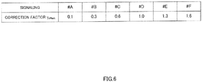
- base station 100 uses a correction factor ⁇ offset of a value less than 1.0 (any of the correction factors for the signaling #A to #C shown in FIG.6 ).
- base station 100 uses a correction factor ⁇ offset exceeding 1.0 (one of correction factors for the signaling #E and #F shown in FIG.6 ).
- Base station 100 notifies terminal 200 of setting information including control parameters including the selected correction factor ⁇ offset (the signaling number of the correction factor ⁇ offset ) via the upper layers.
- resource amount determining section 204 uses a correction factor ⁇ offset set in accordance with a difference in coding rate (a difference in reception quality) between the two CWs to correct the amount of the resource determined based on the coding rate (inverse) of one of the two CWs.
- resource amount determining section 204 can reduce the excess use of resource for the other CW (CW#1 in this case) by multiplying the amount of the resource determined based on the inverse of the lower coding rate by a correction factor ⁇ offset of a value less than 1.0.
- resource amount determining section 204 can increase the amount of the resource of the other CW by multiplying the amount of the resource determined based on the inverse of the higher coding rate by a correction factor ⁇ offset of a value exceeding 1.0.
- equation 5 corrects the amount of the resource determined based on the coding rate of one of CWs (coding rate r CW#0 of CW#0 in this case) with a correction factor ⁇ offset set in accordance with a difference in coding rate between the two CWs, thereby allowing the calculation of the amount of the resource based on the two CWs (i.e., required reception quality of a combined CW obtained by combining the two CWs).
- resource amount determining section 204 corrects the coding rate (inverse) of one of the two CWs in accordance with the difference in coding rate between the two CWs. More specifically, resource amount determining section 204 adjusts the corrected coding rate such that the coding rate is approximated to the average of the coding rates of the two CWs by adopting a larger correction factor ( ⁇ offset ) for the coding rate (i.e., inverse) of one of the two CWs in response to a larger difference in coding rate between the two CWs.
- ⁇ offset correction factor
- the inverse of the corrected coding rate corresponds to the average of the inverses of the coding rates of the two CWs (i.e., the value to which the corrected coding rate is approximated).
- Resource amount determining section 204 determines the amount of the resource of control information in each layer based on the average of the inverses of the coding rates of the two CWs (i.e., the inverse of the corrected coding rate (y offset /r CW#0 in equation 5).
- resource amount determining section 204 determines the amount of the resource required to allocate control information in each layer based on the inverse of the coding rate of one CW and a correction factor set in accordance with a difference in coding rate between the two CWs. In this manner, the amount of the resource in consideration of both of the two CWs can be determined, which in turn, prevents the degradation in reception quality of control information while reducing wasteful use of resource.
- a plurality of correction factor ⁇ offset candidate tables may be provided and switched depending on whether the coding rate r CW#0 of CW#0 in equation 5 is the lower or higher coding rate of the coding rates of two CWs. For example, if the coding rate r CW#0 of CW#0 in equation 5 is the lower coding rate of the coding rates of the two CWs, a candidate table containing the correction factors ⁇ offset for the signaling #A to #D shown in FIG.6 may be used.
- a candidate table containing correction factors ⁇ offset for the signaling #D to #E shown in FIG.6 may be used.
- Determination Method 4 is identical to Determination Method 3 (equation 5) in that the amount of the resource of control information is calculated based on the coding rate (inverse) of one of the two CWs, except for the calculation method of the correction factor.
- reception quality of (“reception quality of a combined CW"/"reception quality of one of the two CWs") fold is obtained after combining the two CWs.
- the "reception quality of a combined CW” is obtained when the two CWs are combined.
- the correction factor for the amount of the resource of control information calculated based on the coding rate (inverse) of one of CWs may be set to ("reception quality of one of CWs"/"reception quality of a combined CW"). This ensures the reception quality necessary to maintain the reception quality required by each CW to which control information is allocated at a minimum amount of resource required after combination of the two CWs.
- reception quality In general, the following relationship holds between the reception quality and the coding rate: The higher the reception quality of a signal is, the higher the coding rate of the signal is. Thus, (“coding rate of one of CWs"/"coding rate of a combined CW”) can be substituted for ("reception quality of one of CWs"/"reception quality of a combined CW”) as a correction factor.
- the "coding rate of a combined CW” is obtained by combining two CWs.
- Resource amount determining section 204 uses equation 6 below to set a correction factor ⁇ offset which is represented by ("coding rate of one of CWs (r CW#0 )"/"coding rate of a combined CW (r CW#0 + CW#1 )").
- ⁇ offset which is represented by ("coding rate of one of CWs (r CW#0 )"/"coding rate of a combined CW (r CW#0 + CW#1 )").
- the coding rate r CW#0 of CW#0 of the CW#0 and CW#1 is used as the "coding rate of one of CWs".
- M CW#0SC PUSCH-initial indicates a PUSCH transmission bandwidth for CW#0
- M CW#1SC PUSCH-initial indicates a PUSCH transmission bandwidth for CW#1
- N CW#0Symb PUSCH-initial indicates the number of transmission symbols in PUSCH per unit transmission bandwidth for CW#0
- N CW#1Symb PUSCH-initial indicates the number of transmission symbols in PUSCH per unit transmission bandwidth for CW#1.
- C CW#0 indicates the number of code blocks into which a data signal allocated in CW#0 is divided
- C CW#1 indicates the number of code blocks into which a data signal allocated in CW#1 is divided
- K r CW#0 indicates the number of bits in each code block in CW#0
- K r CW#1 indicates the number of bits in each code block in CW#1.
- the amount of the resource of CW#0 is 288 (RE).
- the M CW#0SC PUSCH-initial equals 12 sub-carriers
- M CW#0SC PUSCH-initial , M CW#1SC PUSCH-initial , N CW#0Symb PUSCH-initial and N CW#1Symb PUSCH-initial represent values at initial transmission.
- Equation 6 indicates the total amount of transmission resources of respective data signals in CW#0 and CW#1, and ( ⁇ K r CW#0 + ⁇ K r CW#1 ) indicates the total number of transmission symbols in a PUSCH (or the total number of bits in CW#0 and CW#1) to which respective data signals in CW#0 and CW#1 (all code blocks) are assigned.
- Resource amount determining section 204 assigns the correction factor ⁇ offset shown in equation 6 to, for example, equation 5.
- Resource amount determining section 204 determines the amount of the resource of control information Q CW#0 + CW#1 in each layer in accordance with equation 7 below:
- Resource amount determining section 204 determines the amount of the resource of control information in each layer by multiplying the inverse (1/r CW#0 ) of the coding rate r CW#0 by an amount of offset ⁇ offset PUSCH to obtain an amount of resource, multiplying the resulting amount of resource by a correction factor ⁇ offset , and then dividing the result by the total number of layers L.
- the inverse of the coding rate of a combined CW (1/(coding rate of a combined CW (r CW#0 + CW#1 )))
- the average of the inverses of the coding rates of the two CWs can be obtained by correcting the inverse of the coding rate of one of the two CWs (1/r CW#0 ) with a correction factor ⁇ offset (equation 6).
- resource amount determining section 204 uses the inverse of the coding rate of a combined CW as the average of the inverses of the coding rates of the two CWs to determine the amount of the resource of control information in each layer.
- resource amount determining section 204 determines the amount of the resource required to allocate control information in each layer based on the inverse of the coding rate of one of CWs, and the correction factor calculated based on the ratio of reception quality (i.e., the ratio of coding rates) between the two CWs.
- resource amount determining section 204 uses the ratio between the coding rate (reception quality) of one of CWs and the coding rate (reception quality) of a combined CW obtained by combining the two CWs, that is, the ratio of coding rates (i.e., ratio of reception quality) between the two CWs as a correction factor.
- Determination Method 4 can determine the amount of the resource in consideration of both the two CWs, thus preventing the degradation of reception quality of control information without wasteful use of resource.
- Determination Method 4 allows terminal 200 to calculate a correction factor based on the coding rates (reception quality) of the two CWs, thus eliminating the need for base station 100 to notify terminal 200 of a correction factor, unlike in Determination Method 3. More specifically, Determination Method 4 can reduce the amount of signaling from base station 100 to terminal 200, as compared with Determination Method 3.
- the denominator of the correction factor ⁇ offset shown in equation 6 indicates the total number of bits in CW#0 and CW#1. Accordingly, even if the coding rate of either CW#0 or CW#1 is extremely low (data size is extremely small), the correction factor ⁇ offset is determined, taking the coding rate of the other CW into account, thereby preventing assignment of an excess amount of resource to the control information.
- the amount of the resource allocated to control information transmitted in each of a plurality of layers is equal.
- resource amount determining section 204 should preferably determine the amount of the resource of control information in each layer based on the number of bits that can be transmitted in the same amount of resource (for example, a certain number of REs (for example, a single RE)) in each layer.
- the coding rate r CW#0 of CW#0 indicates the number of bits in CW#0 that can be transmitted using a single RE
- the coding rate r CW#1 of CW#1 indicates the number of bits in CW#1 that can be transmitted using a single RE.
- this equation indicates that each layer can transmit (W RE /(L CW#0 + L CW#1 )) bits of data signal using a single RE on average.
- (W RE /(L CW#0 + L CW#1 )) may be used as the average of coding rates (i.e., the number of bits that can be transmitted using a single RE) of a CW allocated to each layer. This achieves reception quality necessary to maintain the reception quality required by each CW to which the control information is allocated at a minimum amount of resource required after combination of the two CWs transmitted in a plurality of layers.
- Resource amount determining section 204 determines the amount of the resource of control information Q CW#0 + CW#1 in each layer based on the inverse of the average of the coding rates of the CWs assigned to each layer ((r CW#0 ⁇ L CW#0 + r CW#1 ⁇ L CW#1 )/(L CW#0 + L CW#1 ))).
- Q CW # 0 + CW # 1 ⁇ O + P ⁇ L CW # 0 + L CW # 1 r CW # 0 ⁇ L CW # 0 + r CW # 1 ⁇ L CW # 1 ⁇ ⁇ offset PUSCH / L ⁇
- Resource amount determining section 204 determines the amount of the resource of control information in each layer by multiplying the inverse of the average of the coding rates of the CWs assigned to each layer ((L CW#0 + L CW#1 )/(r CW#0 ⁇ L CW#0 + r CW#1 ⁇ L CW#1 )) by the amount of offset ⁇ offset PUSCH and then dividing the result by the total number of layers L.
- the average of the coding rates of the CWs assigned to each layer ⁇ (r CW#0 ⁇ L CW#0 + r CW#1 ⁇ L CW#1 ) / (L CW#0 + L CW#1 )), as shown in equation 9, can be represented by r CW#0 ⁇ (L CW#0 /(L CW#0 + L CW#1 )) + r CW#1 ⁇ (L CW#1 /(L CW#0 + L CW#1 )).
- the coding rate r CW#0 of CW#0 is weighted by the proportion of the number of layers to which CW#0 is assigned (L CW#0 ) in all the number of layers (L CW#0 + L CW#1 ), and that the coding rate r CW#1 of CW#1 is weighted by the proportion of the number of layers to which CW#1 is assigned (L CW#1 ) in all the number of layers (L CW#0 + L CW#1 ).
- resource amount determining section 204 weights the coding rate of each CW by the proportion of the number of layers to which the CW is assigned in all the layers to which a plurality of CWs are assigned.
- the greater the proportion of the number of layers to which a CW is assigned in all the layers to which a plurality of CWs are assigned is, the greater the weight given to the coding rate of the CW is.
- Determination Method 2 the average of the coding rates of the two CWs is simply calculated, and the number of layers to which each CW is assigned is not taken into account.
- Determination Method 5 equation 9
- the average of the coding rates of a CW in all the layers containing the CW can be calculated accurately.
- resource amount determining section 204 determines the amount of the resource of control information in each layer using the average of the numbers of bits that can be transmitted in the same amount of resource (for example, a single RE) in each layer as the average of the coding rates of the CWs allocated to each layer. In this manner, the amount of the resource in consideration of the two CWs assigned to a plurality of layers can be determined. Thus, the degradation of reception quality of control information can be prevented without wasteful use of resource.
- Determination Method 5 Since the rank-1 transmission is used for control information, the amount of resource is identical for each layer. In contrast, a transmission mode other than the rank-1 transmission may be used for data signals, in which case the amount of the resource varies depending on layers. In such a case, the same amount of resource is assumed for each layer and the average number of transmittable bits is calculated, as shown in Determination Method 5, which allows calculation of an appropriate amount of resource. In other words, Determination Method 5 is applicable to data signals with different transmission bandwidths.
- CW#0 is responded with ACK and CW#1 is responded with NACK
- retransmission i.e., in sub-frame 8
- CW#0 is assigned for CW#0
- CW#1 is responded with NACK
- retransmission i.e., in sub-frame 8
- CW#0 is assigned for CW#0
- CW#1 is assigned for CW#1.
- the amount of the resource of control information is calculated by assigning the information on CW#0 that is transmitted initially in sub-frame 8 as CW#0 information, and the information on CW#1 that was transmitted initially in sub-frame 0 in equation 9 as CW#1 information.
- This method allows calculations of the amount of the resource, assuming that each layer uses the same amount of resource to transmit control information, and is effective when the same control information in a plurality of layers is transmitted at the same time and at the same frequency, that is, when rank-1 transmission is performed.
- Determination Method 5 allows terminal 200 to calculate the correction factor based on the coding rates (reception quality) of the two CWs, thereby eliminating the need for base station 100 to notify terminal 200 of the correction factor, unlike in Determination Method 3. Accordingly, Determination Method 5 can reduce the amount of signaling from base station 100 to terminal 200, as compared with Determination Method 3.
- the denominator of the portion corresponding to the inverse of the coding rates in equation 9 indicates the total number of bits transmittable using a single RE in all the layers to which CW#0 and CW#1 are assigned. This can prevent assignment of an excess amount of resource to control information since the coding rate of the other CW is taken into account, even if either CW#0 or CW#1 has an extremely lower coding rate (extremely small data size).
- M CW#0SC PUSCH-initial ⁇ N CW#0Symb PUSCH-initial M SC PUSCH-initial (0) ⁇ N Symb PUSCH-initial (0) ⁇ L CW#0 .
- M CW#1SC PUSCH-initial ⁇ N CW#1Symb PUSCH-initial M SC PUSCH-initial(1) ⁇ N Symb PUSCH-initial(1) ⁇ L CW#1 .
- the M SC PUSCH-initial (0) .N Symb PUSCH-initial (0) indicates an amount of the resource of data signals on initial transmission for each of layers to which CW#0 is assigned
- equation 9 can be simplified to equation 12.
- Equation 12 ((L CW#0 + L CW#1 ) ⁇ W layer ) in equation 12 is equivalent to equation 13 below: M CW # 0 sc PUSCH ⁇ initial ⁇ N CW # 0 symb PUSCH ⁇ initial + M CW # 1 sc PUSCH ⁇ initial ⁇ N CW # 1 symb PUSCH ⁇ initial
- equation 10 can be simplified to equation 14 below:
- ACK/NACK and CQI receiving section 111 of base station 100 determines the amount of the resource of control information (ACK/NACK signals or CQIs) in a reception signal using a method similar to Determination Methods 1 to 5 used in resource amount determining section 204. Based on the determined amount of the resource, ACK/NACK and CQI receiving section 111 extracts an ACK/NACK or CQI to downlink data (PDSCH signals) sent by each terminal from a channel (for example, PUSCH) to which uplink data signals have been assigned.
- PDSCH signals downlink data
- this embodiment can prevent the degradation in reception quality of control information even in the case of adopting the SU-MIMO transmission method.
- the amount of the resource of control information is determined based on the lower coding rate of the coding rates of the two CWs (code words) or the average of the inverses of the coding rates of the two CWs. Meanwhile, in Embodiment 2, besides the processing in Embodiment 1, the amount of the resource of control information is determined in consideration of a difference in interference between layers for data signals and for control information.
- FIGs.4 and 5 are used to describe Embodiment 2.
- setting section 101 ( FIG.4 ) in base station 100 in accordance with Embodiment 2 sets a correction factor ( ⁇ offset (L)).
- ACK/NACK and CQI receiving section 111 determines the amount of the resource using the correction factor ( ⁇ offset (L)) received from setting section 101
- resource amount determining section 204 in terminal 200 according to Embodiment 2 uses a correction factor ( ⁇ offset (L)) notified from base station 100 to determine the amount of the resource.
- base station 100 and terminal 200 having the above-mentioned configurations will be described below:
- the same inter-layer interference occurs between data signals and control information. For example, if spatial multiplexing is performed with CW#0 to which control information is allocated and which is assigned to layer #0 and CW#1 containing data signals assigned to layer #1, a rank-2 transmission is performed for data signals and for control information, causing inter-layer interference of the same level.
- resource amount determining section 204 increases or decreases the amount of the resource calculated with an above equation (for example, equation 1), depending on the number of ranks or the number of layers for data signals and for control information.
- resource amount determining section 204 calculates the amount of the resource Q CW#0 + CW#1 by determining the amount of the resource of control information in each layer based on the coding rate of one of CWs (CW#0 or CW#1) or the coding rates of both CWs using the above equation 1, multiplying the determined amount of the resource by a correction factor ⁇ offset (L) which depends on the number of ranks or the number of layers, and then dividing the result of multiplication by the total number of layers L.
- Q CW # 0 + CW # 1 ⁇ O + P ⁇ 1 r CW # 0 ⁇ ⁇ offset PUSCH / L ⁇ ⁇ offset L ⁇
- ⁇ offset (L) represents a correction factor that depends on the number of layers or the number of ranks for data signals and for control information.
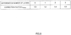
- the correction factor ⁇ offset (L), as shown in FIG.7 implicitly decrease as a difference in the number of ranks or the number of layers between data signals and control information increases. As the difference in the number of ranks or the number of layers between data signals and control information decreases, the correction factor is approximated to 1.0.
- the correction factor ⁇ offset (L), as shown in FIG.8 implicitly increases as a difference in the number of ranks or the number of layers between data signals and control information increases.
- the inter-layer interference is dependent on channel variations (or channel matrix): thus, inter-layer interference varies even if the number of ranks or the number of layers is identical, which means an appropriate correction is difficult using one set value.
- a plurality of correction factors ⁇ offset shared between base station 100 and terminal 200 are provided in each layer to allow base station 100 to select one from the correction factors and notify terminal 200 via upper layers or PDCCH.
- Terminal 200 receives the correction factor ⁇ offset from base station 100 and uses it to calculate the amount of the resource, as in Determination Method 6.
- Base station 100 may report the amount of offset ⁇ offset PUSCH for each layer (or each rank).
- the amount of the resource can be set in consideration of a difference in inter-layer interference between data signals and control information.
- the degradation of reception quality of control information can be prevented, while wasteful use of resource can be reduced.
- the above-mentioned correction factor has a variable set value, depending on the control information (ACK/NACK signals and CQIs and/or the like), but a common notification (notification using a common set value) may be used for the control information (ACK/NACK signals and CQIs and/or the like). For example, if a set value 1 is conveyed to a terminal, the terminal selects a correction factor for ACK/NACK signals that corresponds to the set value 1 and a correction factor for CQIs that corresponds to the set value 1. This allows notification using a single set value for a plurality of parts of control information, thereby reducing the amount of signaling for notification of a correction factor.
- the correction factor is increased or decreased, depending on the number of ranks or the number of layers for data signals and for control information, but since the number of layers and the number of ranks are closely related with CWs, the correction factor may be increased or decreased, depending on the number of CWs containing data signals and control information. Furthermore, the correction factor may be changed, depending on whether the number of ranks, the number of layers or the number of CWs for data signals and for control information is equal to or exceeds 1.
- Embodiment 1 assumes that the number of layers is identical between initial transmission and retransmission. In contrast, in Embodiment 3, the amount of the resource of control information is determined in consideration of a difference in the number of layers between initial transmission and retransmission in the processing shown in Embodiment 1.
- FIGs.4 and 5 are used to describe Embodiment 3.
- ACK/NACK and CQI receiving section 111 in base station 100 according to Embodiment 3 performs processing similar to that of Embodiment 1 and calculates the amount of the resource required to allocate control information based on the number of layers on initial transmission and on retransmission.
- ACK/NACK and CQI receiving section 111 in Embodiment 3 differs from that in Embodiment 1 in that the equation to calculate the amount of the resource of control information is expanded.
- resource amount determining section 204 in terminal 200 according to Embodiment 3 performs processing similar to that of Embodiment 1 and calculates the amount of the resource required to allocate control information based on the number of layers on initial transmission and retransmission.
- Resource amount determining section 204 in Embodiment 3 differs from that in Embodiment 1 in that the equation to calculate the amount of the resource of control information is expanded.
- base station 100 and terminal 200 having the above-mentioned configurations will be described.
- Determination Methods 1 to 6 assume that the number of layers is identical between initial transmission and retransmission. On initial transmission, the reception quality that is equal to or greater than a certain level (required reception quality) can be achieved for control information by setting the amount of the resource of control information using, for example, equation 9 (Determination Method 5).
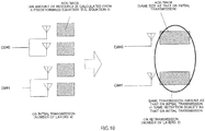
- Determination Methods 1 to 6 (for example, equation 9) assume that the amount of the resource of control information is identical for each layer between initial transmission and retransmission, the total amount of the resource of control information in all the layers also decreases due to a reduction in the number of layers when the number of layers is changed on retransmission (for example, decreases). This results in the degradation of reception quality of control information on retransmission, as compared with that on initial transmission (for example, see FIG.9 ).
- allocation notification information (UL grant) is used to change the number of layers from four (on initial transmission) to two (on retransmission)
- the amount of resource of data signals decreases and thus the total amount of the resource of control information (for example, ACK/NACK signals) also decreases in all the layers.
- resource amount determining section 204 re-sets the amount of the resource of control information on retransmission based on the number of layers in which each CW is allocated on retransmission. More specifically, on retransmission, resource amount determining section 204 does not use the amount of the resource per layer which was calculated on initial transmission, and instead, assigns the number of layers in which each CW is allocated on retransmission (i.e., current number) in equation 9 to re-calculate the amount of the resource per layer on retransmission (i.e., current amount).
- L CW#0 current and L CW#1 current indicate the number of layers to which CW#0 and CW#1 are assigned on retransmission (i.e., currently), respectively, and L CW#0 initial and L CW#1 initial indicate the number of layers to which CW#0 and CW#1 are assigned on initial transmission, respectively. Since Determination Methods 1 to 6 assume that the number of layers is identical between initial transmission and retransmission, the number of layers is not considered on initial transmission and retransmission. Hence, the number of layers used in Determination Methods 1 to 6 represents the information on initial transmission, just like the number of bits in each CW and/or the amount of the resource in each CW.
- Equation 16 is derived by multiplying each term in the denominator of equation 9 by the ratio of the number of layers on retransmission to that on initial transmission (i.e., L CW#0 current /L CW#0 initial , L CW#1 current /L CW#1 initial ). Equation 17 is derived from equations 16 and 11.
- Equation 19 indicates that if the number of layers for transmitting data signals decreases, the amount of the resource of control information per layer increases. This means that the total amount of resource of layers containing control information is almost identical (i.e., the number of layers containing control information ⁇ the amount of the resource of control information per layer) is almost identical) between initial transmission and retransmission, thereby achieving the reception quality that is equal to or exceeds a certain level (required reception quality) for control information even on retransmission (see FIG.10 .).
- equation 18 may be substituted for equation 17.
- L initial and L current indicate the total number of layers on initial transmission and on retransmission, respectively.
- the amount of the resource of control information may be excessive or insufficient, which results in wasteful use of the resource or low quality. If the probability of not meeting the above condition is low, or if the system is designed so as to avoid such occurrence, resource amount determining section 204 may use equation 18 to calculate the amount of the resource of control information.
- resource amount determining section 204 may use equation 16, 17 or 18 to prevent the assignment of an excess amount of resource to control information.
- the number of layers may be replaced with the number of antenna ports.
- the number of layers on initial transmission in the above description i.e., four layers in FIG.10
- the number of layers on retransmission (currently) is replaced with the number of antenna ports on retransmission (currently) (two ports in FIG.10 )
- the total number of layers is replaced with the total number of antenna ports.
- resource amount determining section 204 replaces the number of layers in equation 16, 17 or 18 with the number of antenna ports to calculate the amount of the resource of control information.
- the number of layers is defined as the number of antenna ports through which different signaling sequences are transmitted, the number of layers is not always identical to the number of antenna ports. For example, when a rank-1 transmission is performed through four antenna ports, the number of layers is one since the same signaling sequence is transmitted though the four antenna ports. In this case, if a 4-layer transmission is performed using four antenna ports on initial transmission, while a 1-layer transmission (rank-1 transmission) is performed using four antenna ports on retransmission, the amount of the resource of control information need not be corrected. In contrast, if a 4-layer transmission is performed using four antenna ports on initial transmission, while a 1-layer transmission (using one layer) is performed using one antenna port on retransmission, the amount of the resource of control information needs to be corrected.
- transmission power per antenna port is increased to compensate for the decrease, thereby avoiding the correction of the amount of the resource of control information. For example, if the number of antenna ports is reduced from four to two, the transmission power per antenna port may be increased by 3 dB (i.e., doubled), and if the number of antenna ports is reduced from four to one, the transmission power per antenna port may be increased by 6 dB (i.e., quadruplicated).
- equation 11 or 14 may be used. If a precoding vector (or matrix) in which the number of antenna ports used on retransmission is identical to that on initial transmission is used, equation 11 or 14, for example, may be used. If a precoding vector (or matrix) in which the number of antenna ports used on retransmission is different from that on initial transmission is used, for example, the number of layers in equation 16, 17 or 18 may be used with the number of layers replaced with the number of antenna ports.
- equation 11 or 14 may be used. If signals are retransmitted in a single CW, equation 19 may be used as exception processing. For example, if 4-antenna-port transmission is performed using the two CWs on initial transmission and if 2-antenna-port transmission is performed using a single CW on retransmission, equation 19 is used on retransmission. In the fallback mode, which is used when reception quality undergoes extreme degradation, for example, 1-antenna-port transmission may be performed using a single CW on retransmission, in which case equation 19 may be used as exception processing. Equation 19 may incorporate a correction value as shown in equation 20.
- Correction value W in equation 20 indicates a correction factor.
- Correction value W may be determined based on the number of layers (or number of antenna ports) for CW0 or CW1 on initial transmission and on retransmission.
- the correction value W in equation 20 is the ratio of number of antenna ports to which CW0 or CW1 is assigned on retransmission to the number of antenna ports to which CW0 or CW1 is assigned on initial transmission.
- the correction value W may be included in the amount of offset ⁇ offset PUSCH .
- the amount of offset ⁇ offset PUSCH is determined based on the number of layers (or number of antenna ports) for CW0 or CW1 on initial transmission and on retransmission.
- a reason for calculating the amount of the resource on retransmission using CW information used in initial transmission is that the data signal error rate on retransmission may not be set to a constant value such as 10%. More specifically, on initial transmission, a base station allocates resource to each terminal such that the data signal error rate is 10%, while on retransmission the base station is likely to assign a smaller amount of resource to data signals than on initial transmission since it is sufficient as long as an improvement in the initial data signal error rate on retransmission is made.
- a reduction in the amount of the resource of data signals (i.e., M SC PUSCH-retransmission •N Symb PUSCH-retransmission ) on retransmission results in a reduction in the amount of the resource of control information, which leads to the degradation of reception quality of control information.
- the information on initial transmission is used to determine the amount of resource, thereby keeping the reception quality that is equal to or exceeds a certain level (i.e., required reception quality) for control information.
- ⁇ K r , ⁇ K r CW#0 and ⁇ K r CW#1 are identical between initial transmission and retransmission.
- the correction value (K) is multiplied when the amount of the resource on retransmission is determined. For example, as shown in equation 21, the ratio of the number of layers for each CW on initial transmission (L CW#0 initial , L CW#1 initial ) to the number of layers for each CW on retransmission (L CW#0 current , L CW#1 current ) may be multiplied by a correction value specific to the term generated for each CW (L CW#0 , K CW#1 ).
- the ratio of the number of layers (L initial ) on initial transmission to the number of layers (L current ) on retransmission may be multiplied by the correction value (K).
- Correction values are not limited to the above-mentioned examples, and one or more time delays may be multiplied by a correction value.
- a restriction that the same number of layers as that on initial transmission should be always used on retransmission may be imposed. For example, changing the number of layers for each CW on retransmission with allocation information (UL grant) or the like may be prohibited. ACK/NACKs may be transmitted in the same number of layers as that on initial transmission even if the number of layers for each CW decreases on retransmission.
- the antenna port refers to a logical antenna composed of one or more physical antennas.
- an antenna port does not necessarily refer to one physical antenna, and may refer to an antenna array composed of a plurality of antennas.
- an antenna port is specified as a minimum unit allowing the base station to transmit a different reference signal.
- the antenna port may be specified as a minimum unit in multiplication of a weight of the precoding vector.
- the number of layers may be defined as the number of different data signals transmitted concurrently in the space.
- the layer may be defined as a signal transmitted through an antenna port associated with data signals or reference signals (or as a communication path thereof in the space).
- a vector used for weight control (precoding vector) that has been studied for uplink demodulation pilot signals in LTE-A has one-to-one relationship with a layer.
- LSIs are integrated circuits.
- the integrated circuits may be implemented individually into separate chips, or all or part of the integrated circuit may be implemented into one chip. Although such integrated circuits are referred to as LSIs herein, they may be called ICs, system LSIs, super LSIs or ultra LSIs, depending on the degree of integration.
- the methods for manufacturing integrated circuits are not limited to LSIs, and dedicated circuits or general-purpose processors may be used to implement them.
- FPGAs field programmable gate arrays
- reconfigurable processors that allow connection or setting of circuit cells within LSIs may be used.
- the present invention is useful in mobile communication systems and/or the like.
Priority Applications (6)
| Application Number | Priority Date | Filing Date | Title |
|---|---|---|---|
| EP19216981.1A EP3694250B1 (en) | 2010-06-21 | 2011-06-07 | Apparatus and communication method thereof |
| PL11797776T PL2584827T3 (pl) | 2010-06-21 | 2011-06-07 | Urządzenie końcowe i wykorzystywany w nim sposób komunikowania się |
| RS20180694A RS57335B1 (sr) | 2010-06-21 | 2011-06-07 | Terminalni uređaji i komunikaciona metoda koja se pri tome koristi |
| SI201131486T SI2584827T1 (en) | 2010-06-21 | 2011-06-07 | Terminal apparatus and communication procedure thereof |
| EP18152437.2A EP3340675B1 (en) | 2010-06-21 | 2011-06-07 | Terminal apparatus and communication method thereof |
| HRP20180949TT HRP20180949T1 (hr) | 2010-06-21 | 2018-06-19 | Terminalni uređaj i postupak komunikacije istog |
Applications Claiming Priority (3)
| Application Number | Priority Date | Filing Date | Title |
|---|---|---|---|
| JP2010140751 | 2010-06-21 | ||
| JP2010221392 | 2010-09-30 | ||
| PCT/JP2011/003198 WO2011161887A1 (ja) | 2010-06-21 | 2011-06-07 | 端末装置及びその通信方法 |
Related Child Applications (3)
| Application Number | Title | Priority Date | Filing Date |
|---|---|---|---|
| EP19216981.1A Division EP3694250B1 (en) | 2010-06-21 | 2011-06-07 | Apparatus and communication method thereof |
| EP18152437.2A Division EP3340675B1 (en) | 2010-06-21 | 2011-06-07 | Terminal apparatus and communication method thereof |
| EP18152437.2A Division-Into EP3340675B1 (en) | 2010-06-21 | 2011-06-07 | Terminal apparatus and communication method thereof |
Publications (3)
| Publication Number | Publication Date |
|---|---|
| EP2584827A1 EP2584827A1 (en) | 2013-04-24 |
| EP2584827A4 EP2584827A4 (en) | 2017-08-09 |
| EP2584827B1 true EP2584827B1 (en) | 2018-03-21 |
Family
ID=45371094
Family Applications (3)
| Application Number | Title | Priority Date | Filing Date |
|---|---|---|---|
| EP18152437.2A Active EP3340675B1 (en) | 2010-06-21 | 2011-06-07 | Terminal apparatus and communication method thereof |
| EP11797776.9A Active EP2584827B1 (en) | 2010-06-21 | 2011-06-07 | Terminal apparatus and communication method thereof |
| EP19216981.1A Active EP3694250B1 (en) | 2010-06-21 | 2011-06-07 | Apparatus and communication method thereof |
Family Applications Before (1)
| Application Number | Title | Priority Date | Filing Date |
|---|---|---|---|
| EP18152437.2A Active EP3340675B1 (en) | 2010-06-21 | 2011-06-07 | Terminal apparatus and communication method thereof |
Family Applications After (1)
| Application Number | Title | Priority Date | Filing Date |
|---|---|---|---|
| EP19216981.1A Active EP3694250B1 (en) | 2010-06-21 | 2011-06-07 | Apparatus and communication method thereof |
Country Status (21)
| Country | Link |
|---|---|
| US (8) | US8830911B2 (da) |
| EP (3) | EP3340675B1 (da) |
| JP (2) | JP5715129B2 (da) |
| KR (2) | KR101833695B1 (da) |
| CN (2) | CN102934482B (da) |
| AU (1) | AU2011270584B2 (da) |
| BR (1) | BR112012031268B1 (da) |
| CY (1) | CY1120539T1 (da) |
| DK (1) | DK2584827T3 (da) |
| ES (1) | ES2668811T3 (da) |
| HR (1) | HRP20180949T1 (da) |
| HU (1) | HUE038240T2 (da) |
| LT (1) | LT2584827T (da) |
| PL (1) | PL2584827T3 (da) |
| PT (1) | PT2584827T (da) |
| RS (1) | RS57335B1 (da) |
| RU (2) | RU2556877C2 (da) |
| SG (2) | SG186233A1 (da) |
| SI (1) | SI2584827T1 (da) |
| TW (2) | TWI514803B (da) |
| WO (1) | WO2011161887A1 (da) |
Families Citing this family (17)
| Publication number | Priority date | Publication date | Assignee | Title |
|---|---|---|---|---|
| CN102960039B (zh) * | 2010-07-09 | 2015-08-26 | 日本电气株式会社 | 通信设备和资源导出方法 |
| US8848557B2 (en) * | 2010-08-25 | 2014-09-30 | Samsung Electronics Co., Ltd. | Multiplexing of control and data in UL MIMO system based on SC-FDM |
| US9008225B2 (en) * | 2011-04-19 | 2015-04-14 | Panasonic Intellectual Property Corporation Of America | Pre-coding method and pre-coding device |
| JP6442781B2 (ja) * | 2013-07-19 | 2018-12-26 | シャープ株式会社 | 端末装置 |
| DE112015006784T5 (de) * | 2015-08-07 | 2018-04-19 | Intel IP Corporation | UCI für die Carrier Aggregation |
| KR102397154B1 (ko) | 2015-12-01 | 2022-05-13 | 텔레호낙티에볼라게트 엘엠 에릭슨(피유비엘) | 예측적 확인응답 피드백 메커니즘 |
| EP4075704A1 (en) * | 2016-05-11 | 2022-10-19 | IDAC Holdings, Inc. | Physical (phy) layer solutions to support use of mixed numerologies in the same channel |
| CN109076512B (zh) * | 2016-05-13 | 2021-02-23 | 华为技术有限公司 | 控制信息发送、接收方法和设备 |
| EP3577835B1 (en) * | 2017-02-06 | 2022-11-30 | Motorola Mobility LLC | Method and apparatus for short pdcch operation |
| CN110582946A (zh) * | 2017-03-10 | 2019-12-17 | 株式会社Ntt都科摩 | 用户终端以及无线通信方法 |
| JP6844025B2 (ja) * | 2017-03-20 | 2021-03-17 | エルジー エレクトロニクス インコーポレイティド | 次世代通信システムにおいてコードワードとレイヤをマッピングする方法及びそのための装置 |
| WO2018182242A2 (ko) * | 2017-03-25 | 2018-10-04 | 엘지전자 주식회사 | 무선 통신 시스템에서 위상 잡음 제거를 위한 ptrs 수신 방법 및 그 장치 |
| WO2019024116A1 (zh) | 2017-08-04 | 2019-02-07 | Oppo广东移动通信有限公司 | 信息处理方法、通信设备和计算机存储介质 |
| US11601223B2 (en) * | 2017-08-18 | 2023-03-07 | Qualcomm Incorporated | Systems and methods for HARQ transmission and retransmission using multiple code words |
| US11516834B2 (en) * | 2017-11-13 | 2022-11-29 | Qualcomm Incorporated | Uplink control information transmission |
| US11812433B2 (en) * | 2017-11-17 | 2023-11-07 | Ntt Docomo, Inc. | User terminal and radio communication method |
| JP6947291B2 (ja) * | 2018-03-30 | 2021-10-13 | 富士通株式会社 | 基地局、無線通信端末、無線通信システム、及び無線通信方法 |
Family Cites Families (30)
| Publication number | Priority date | Publication date | Assignee | Title |
|---|---|---|---|---|
| US7130587B2 (en) * | 2001-08-22 | 2006-10-31 | National Institute of Information and Communications Technology Incorporated, Administrative Agency | Communication quality estimation method, communication quality estimation apparatus, and communication system |
| JP4675167B2 (ja) * | 2005-06-14 | 2011-04-20 | 株式会社エヌ・ティ・ティ・ドコモ | チャネル割り当て方法、無線通信システム、基地局装置、ユーザ端末 |
| JP4668843B2 (ja) * | 2006-05-26 | 2011-04-13 | 富士通株式会社 | 無線基地局受信装置及びプログラム |
| CN101132608A (zh) * | 2006-08-22 | 2008-02-27 | 北京三星通信技术研究有限公司 | 指示信道资源分配信息的设备和方法 |
| MX2009004838A (es) | 2006-11-06 | 2009-05-15 | Qualcomm Inc | Transmision mimo con permutacion de capa en un sistema de comunicacion inalambrica. |
| EP1944896A1 (en) | 2007-01-09 | 2008-07-16 | Matsushita Electric Industrial Co., Ltd. | Configuration of control channels in a mobile communication system |
| JP4671982B2 (ja) * | 2007-01-09 | 2011-04-20 | 株式会社エヌ・ティ・ティ・ドコモ | 基地局、送信方法及び移動通信システム |
| CN101595763B (zh) * | 2007-01-31 | 2012-01-25 | 富士通株式会社 | 无线通信控制方法、无线基站和无线终端 |
| CN101296207B (zh) * | 2007-04-28 | 2011-08-10 | 华为技术有限公司 | 控制信令的传输方法、网络侧设备以及终端 |
| JP5131998B2 (ja) | 2007-06-15 | 2013-01-30 | パナソニック株式会社 | 無線通信装置、無線通信システム及び無線通信方法 |
| EP2086267B1 (en) * | 2008-02-04 | 2015-09-30 | Samsung Electronics Co., Ltd. | Autonomous user equipment transmission power control in communications systems |
| DK2291940T4 (da) * | 2008-02-06 | 2018-08-13 | Ericsson Telefon Ab L M | Fremgangsmåder og anordninger i forbindelse med downlink-tildelinger |
| JP5356503B2 (ja) | 2008-04-28 | 2013-12-04 | ノキア シーメンス ネットワークス オサケユキチュア | 変調及びコード化スキームをリソースの量にリンクするための方法及び装置 |
| KR101591086B1 (ko) * | 2008-05-21 | 2016-02-03 | 엘지전자 주식회사 | 다중 안테나 시스템에서 harq 수행 방법 |
| KR100925444B1 (ko) * | 2008-05-27 | 2009-11-06 | 엘지전자 주식회사 | 상향링크 채널을 통해 데이터와 제어 정보를 포함하는 상향링크 신호를 전송하는 방법 |
| CA2729510A1 (en) * | 2008-06-30 | 2010-01-07 | Nokia Siemens Networks Oy | Selecting between normal and virtual dual layer ack/nack |
| US8503425B2 (en) * | 2008-07-22 | 2013-08-06 | Lg Electronics Inc. | Method for allocating phich and generating reference signal in system using single-user MIMO based on multiple codewords when transmitting uplink |
| WO2010064407A1 (ja) * | 2008-12-02 | 2010-06-10 | パナソニック株式会社 | 符号化率設定方法及び無線通信装置 |
| JP2010140751A (ja) | 2008-12-11 | 2010-06-24 | Nsk Ltd | 発電素子 |
| US8625554B2 (en) * | 2009-01-30 | 2014-01-07 | Samsung Electronics Co., Ltd. | System and method for uplink data and control signal transmission in MIMO wireless systems |
| JP2010221392A (ja) | 2009-02-25 | 2010-10-07 | Kyocera Corp | 光通信用スリーブの内径研磨ピン並びにこれを用いた内径研磨装置および製造方法 |
| US8848634B2 (en) * | 2009-04-28 | 2014-09-30 | Nec Corporation | Base station apparatus, radio communication system, control method of base station, and control method of radio communication system |
| CN101695017A (zh) * | 2009-10-27 | 2010-04-14 | 中兴通讯股份有限公司 | 物理上行共享信道传输上行控制信令的方法与装置 |
| CN101702631A (zh) * | 2009-11-04 | 2010-05-05 | 中兴通讯股份有限公司 | 上行控制信令传输方法和装置 |
| US8958380B2 (en) * | 2010-03-22 | 2015-02-17 | Lg Electronics Inc. | Method and device for transmitting control information |
| US9100155B2 (en) * | 2010-05-03 | 2015-08-04 | Qualcomm Incorporated | Method and apparatus for control and data multiplexing in wireless communication |
| US8989156B2 (en) * | 2010-06-18 | 2015-03-24 | Sharp Kabushiki Kaisha | Selecting a codeword and determining a symbol length for uplink control information |
| KR101630502B1 (ko) * | 2010-08-13 | 2016-06-14 | 제트티이 (유에스에이) 잉크. | 물리적 업링크 공유 채널상에서 업링크 제어 정보를 다중화하기 위한 방법 |
| US8848557B2 (en) * | 2010-08-25 | 2014-09-30 | Samsung Electronics Co., Ltd. | Multiplexing of control and data in UL MIMO system based on SC-FDM |
| WO2012067443A2 (ko) * | 2010-11-17 | 2012-05-24 | 엘지전자 주식회사 | 무선 접속 시스템에서 상향링크 제어정보 송신 방법 및 이를 위한 단말 |
-
2011
- 2011-06-07 RS RS20180694A patent/RS57335B1/sr unknown
- 2011-06-07 SI SI201131486T patent/SI2584827T1/en unknown
- 2011-06-07 AU AU2011270584A patent/AU2011270584B2/en active Active
- 2011-06-07 EP EP18152437.2A patent/EP3340675B1/en active Active
- 2011-06-07 SG SG2012090320A patent/SG186233A1/en unknown
- 2011-06-07 DK DK11797776.9T patent/DK2584827T3/da active
- 2011-06-07 KR KR1020177015368A patent/KR101833695B1/ko active IP Right Grant
- 2011-06-07 KR KR1020127031949A patent/KR101747480B1/ko active IP Right Grant
- 2011-06-07 BR BR112012031268-5A patent/BR112012031268B1/pt active IP Right Grant
- 2011-06-07 CN CN201180026631.5A patent/CN102934482B/zh active Active
- 2011-06-07 EP EP11797776.9A patent/EP2584827B1/en active Active
- 2011-06-07 RU RU2012152641/07A patent/RU2556877C2/ru active
- 2011-06-07 ES ES11797776.9T patent/ES2668811T3/es active Active
- 2011-06-07 US US13/699,557 patent/US8830911B2/en active Active
- 2011-06-07 PT PT117977769T patent/PT2584827T/pt unknown
- 2011-06-07 PL PL11797776T patent/PL2584827T3/pl unknown
- 2011-06-07 JP JP2012521285A patent/JP5715129B2/ja active Active
- 2011-06-07 HU HUE11797776A patent/HUE038240T2/hu unknown
- 2011-06-07 EP EP19216981.1A patent/EP3694250B1/en active Active
- 2011-06-07 SG SG10201404644VA patent/SG10201404644VA/en unknown
- 2011-06-07 LT LTEP11797776.9T patent/LT2584827T/lt unknown
- 2011-06-07 CN CN201511009969.6A patent/CN105554814B/zh active Active
- 2011-06-07 WO PCT/JP2011/003198 patent/WO2011161887A1/ja active Application Filing
- 2011-06-20 TW TW100121401A patent/TWI514803B/zh active
- 2011-06-20 TW TW104137384A patent/TWI584608B/zh active
-
2014
- 2014-07-30 US US14/447,259 patent/US9509477B2/en active Active
-
2015
- 2015-03-11 JP JP2015048385A patent/JP5883523B2/ja active Active
- 2015-05-28 RU RU2015120327A patent/RU2659232C2/ru active
-
2016
- 2016-10-14 US US15/294,301 patent/US9755805B2/en active Active
-
2017
- 2017-07-31 US US15/664,689 patent/US10057035B2/en active Active
-
2018
- 2018-05-25 CY CY20181100562T patent/CY1120539T1/el unknown
- 2018-06-19 HR HRP20180949TT patent/HRP20180949T1/hr unknown
- 2018-07-19 US US16/040,304 patent/US10419189B2/en active Active
-
2019
- 2019-08-05 US US16/532,242 patent/US10826666B2/en active Active
-
2020
- 2020-09-24 US US17/031,079 patent/US11533147B2/en active Active
-
2022
- 2022-11-11 US US18/054,852 patent/US11949624B2/en active Active
Non-Patent Citations (1)
| Title |
|---|
| None * |
Also Published As
Similar Documents
| Publication | Publication Date | Title |
|---|---|---|
| US11949624B2 (en) | Communication apparatus and communication method thereof | |
| JP5838197B2 (ja) | アップリンク制御情報をマッピングするための方法及びシステム | |
| EP2306659B1 (en) | Method for allocating phich in a system using su-mimo with multiple codewords in uplink | |
| JPWO2011099282A1 (ja) | 端末及びその通信方法 | |
| AU2014202552B2 (en) | Terminal Apparatus and Communication Method Thereof |
Legal Events
| Date | Code | Title | Description |
|---|---|---|---|
| PUAI | Public reference made under article 153(3) epc to a published international application that has entered the european phase |
Free format text: ORIGINAL CODE: 0009012 |
|
| 17P | Request for examination filed |
Effective date: 20121207 |
|
| AK | Designated contracting states |
Kind code of ref document: A1 Designated state(s): AL AT BE BG CH CY CZ DE DK EE ES FI FR GB GR HR HU IE IS IT LI LT LU LV MC MK MT NL NO PL PT RO RS SE SI SK SM TR |
|
| DAX | Request for extension of the european patent (deleted) | ||
| RAP1 | Party data changed (applicant data changed or rights of an application transferred) |
Owner name: PANASONIC INTELLECTUAL PROPERTY CORPORATION OF AME |
|
| RAP1 | Party data changed (applicant data changed or rights of an application transferred) |
Owner name: SUN PATENT TRUST |
|
| RA4 | Supplementary search report drawn up and despatched (corrected) |
Effective date: 20170707 |
|
| RIC1 | Information provided on ipc code assigned before grant |
Ipc: H04W 28/06 20090101AFI20170704BHEP Ipc: H04J 11/00 20060101ALI20170704BHEP Ipc: H04J 99/00 20090101ALI20170704BHEP Ipc: H04B 7/0413 20170101ALI20170704BHEP Ipc: H04B 7/04 20170101ALI20170704BHEP |
|
| REG | Reference to a national code |
Ref country code: DE Ref legal event code: R079 Ref document number: 602011046758 Country of ref document: DE Free format text: PREVIOUS MAIN CLASS: H04W0028060000 Ipc: H04L0005000000 |
|
| GRAP | Despatch of communication of intention to grant a patent |
Free format text: ORIGINAL CODE: EPIDOSNIGR1 |
|
| STAA | Information on the status of an ep patent application or granted ep patent |
Free format text: STATUS: GRANT OF PATENT IS INTENDED |
|
| RIC1 | Information provided on ipc code assigned before grant |
Ipc: H04J 11/00 20060101ALI20171003BHEP Ipc: H04B 7/0413 20170101ALI20171003BHEP Ipc: H04B 7/04 20170101ALI20171003BHEP Ipc: H04J 99/00 20090101ALI20171003BHEP Ipc: H04W 28/06 20090101ALI20171003BHEP Ipc: H04L 5/00 20060101AFI20171003BHEP |
|
| INTG | Intention to grant announced |
Effective date: 20171030 |
|
| GRAS | Grant fee paid |
Free format text: ORIGINAL CODE: EPIDOSNIGR3 |
|
| GRAA | (expected) grant |
Free format text: ORIGINAL CODE: 0009210 |
|
| STAA | Information on the status of an ep patent application or granted ep patent |
Free format text: STATUS: THE PATENT HAS BEEN GRANTED |
|
| RAP1 | Party data changed (applicant data changed or rights of an application transferred) |
Owner name: SUN PATENT TRUST |
|
| AK | Designated contracting states |
Kind code of ref document: B1 Designated state(s): AL AT BE BG CH CY CZ DE DK EE ES FI FR GB GR HR HU IE IS IT LI LT LU LV MC MK MT NL NO PL PT RO RS SE SI SK SM TR |
|
| REG | Reference to a national code |
Ref country code: GB Ref legal event code: FG4D |
|
| REG | Reference to a national code |
Ref country code: CH Ref legal event code: EP |
|
| REG | Reference to a national code |
Ref country code: AT Ref legal event code: REF Ref document number: 982201 Country of ref document: AT Kind code of ref document: T Effective date: 20180415 |
|
| REG | Reference to a national code |
Ref country code: IE Ref legal event code: FG4D |
|
| REG | Reference to a national code |
Ref country code: DE Ref legal event code: R096 Ref document number: 602011046758 Country of ref document: DE |
|
| REG | Reference to a national code |
Ref country code: ES Ref legal event code: FG2A Ref document number: 2668811 Country of ref document: ES Kind code of ref document: T3 Effective date: 20180522 |
|
| REG | Reference to a national code |
Ref country code: HR Ref legal event code: TUEP Ref document number: P20180949 Country of ref document: HR |
|
| REG | Reference to a national code |
Ref country code: FR Ref legal event code: PLFP Year of fee payment: 8 Ref country code: RO Ref legal event code: EPE |
|
| REG | Reference to a national code |
Ref country code: PT Ref legal event code: SC4A Ref document number: 2584827 Country of ref document: PT Date of ref document: 20180622 Kind code of ref document: T Free format text: AVAILABILITY OF NATIONAL TRANSLATION Effective date: 20180618 |
|
| REG | Reference to a national code |
Ref country code: DK Ref legal event code: T3 Effective date: 20180627 |
|
| REG | Reference to a national code |
Ref country code: EE Ref legal event code: FG4A Ref document number: E015536 Country of ref document: EE Effective date: 20180531 |
|
| REG | Reference to a national code |
Ref country code: SE Ref legal event code: TRGR |
|
| REG | Reference to a national code |
Ref country code: NL Ref legal event code: FP |
|
| REG | Reference to a national code |
Ref country code: HR Ref legal event code: T1PR Ref document number: P20180949 Country of ref document: HR |
|
| REG | Reference to a national code |
Ref country code: NO Ref legal event code: T2 Effective date: 20180321 |
|
| REG | Reference to a national code |
Ref country code: HU Ref legal event code: AG4A Ref document number: E038240 Country of ref document: HU |
|
| REG | Reference to a national code |
Ref country code: GR Ref legal event code: EP Ref document number: 20180401459 Country of ref document: GR Effective date: 20181031 |
|
| REG | Reference to a national code |
Ref country code: CH Ref legal event code: PK Free format text: BERICHTIGUNGEN |
|
| REG | Reference to a national code |
Ref country code: DE Ref legal event code: R097 Ref document number: 602011046758 Country of ref document: DE |
|
| RIC2 | Information provided on ipc code assigned after grant |
Ipc: H04J 11/00 20060101ALI20171003BHEP Ipc: H04B 7/0413 20170101ALI20171003BHEP Ipc: H04W 28/06 20090101ALI20171003BHEP Ipc: H04L 5/00 20060101AFI20171003BHEP Ipc: H04J 99/00 20090101ALI20171003BHEP Ipc: H04B 7/04 20170101ALI20171003BHEP |
|
| PLBE | No opposition filed within time limit |
Free format text: ORIGINAL CODE: 0009261 |
|
| STAA | Information on the status of an ep patent application or granted ep patent |
Free format text: STATUS: NO OPPOSITION FILED WITHIN TIME LIMIT |
|
| REG | Reference to a national code |
Ref country code: CH Ref legal event code: PK Free format text: BERICHTIGUNGEN |
|
| RIC2 | Information provided on ipc code assigned after grant |
Ipc: H04B 7/04 20170101ALI20171003BHEP Ipc: H04J 99/00 20090101ALI20171003BHEP Ipc: H04L 5/00 20060101AFI20171003BHEP Ipc: H04J 11/00 20060101ALI20171003BHEP Ipc: H04B 7/0413 20170101ALI20171003BHEP Ipc: H04W 28/06 20090101ALI20171003BHEP |
|
| 26N | No opposition filed |
Effective date: 20190102 |
|
| REG | Reference to a national code |
Ref country code: HR Ref legal event code: ODRP Ref document number: P20180949 Country of ref document: HR Payment date: 20190527 Year of fee payment: 9 |
|
| REG | Reference to a national code |
Ref country code: HR Ref legal event code: ODRP Ref document number: P20180949 Country of ref document: HR Payment date: 20200602 Year of fee payment: 10 |
|
| REG | Reference to a national code |
Ref country code: HR Ref legal event code: ODRP Ref document number: P20180949 Country of ref document: HR Payment date: 20210602 Year of fee payment: 11 |
|
| REG | Reference to a national code |
Ref country code: AT Ref legal event code: UEP Ref document number: 982201 Country of ref document: AT Kind code of ref document: T Effective date: 20180321 |
|
| REG | Reference to a national code |
Ref country code: HR Ref legal event code: ODRP Ref document number: P20180949 Country of ref document: HR Payment date: 20220607 Year of fee payment: 12 |
|
| REG | Reference to a national code |
Ref country code: HR Ref legal event code: ODRP Ref document number: P20180949 Country of ref document: HR Payment date: 20230601 Year of fee payment: 13 |
|
| P01 | Opt-out of the competence of the unified patent court (upc) registered |
Effective date: 20230509 |
|
| PGFP | Annual fee paid to national office [announced via postgrant information from national office to epo] |
Ref country code: SM Payment date: 20230526 Year of fee payment: 13 Ref country code: RS Payment date: 20230525 Year of fee payment: 13 Ref country code: RO Payment date: 20230525 Year of fee payment: 13 Ref country code: PT Payment date: 20230525 Year of fee payment: 13 Ref country code: NO Payment date: 20230622 Year of fee payment: 13 Ref country code: NL Payment date: 20230620 Year of fee payment: 13 Ref country code: MC Payment date: 20230622 Year of fee payment: 13 Ref country code: LT Payment date: 20230523 Year of fee payment: 13 Ref country code: IE Payment date: 20230620 Year of fee payment: 13 Ref country code: FR Payment date: 20230627 Year of fee payment: 13 Ref country code: EE Payment date: 20230628 Year of fee payment: 13 Ref country code: DK Payment date: 20230622 Year of fee payment: 13 Ref country code: DE Payment date: 20230620 Year of fee payment: 13 Ref country code: CZ Payment date: 20230526 Year of fee payment: 13 Ref country code: CY Payment date: 20230606 Year of fee payment: 13 Ref country code: BG Payment date: 20230627 Year of fee payment: 13 |
|
| PGFP | Annual fee paid to national office [announced via postgrant information from national office to epo] |
Ref country code: TR Payment date: 20230606 Year of fee payment: 13 Ref country code: SK Payment date: 20230530 Year of fee payment: 13 Ref country code: SI Payment date: 20230525 Year of fee payment: 13 Ref country code: SE Payment date: 20230620 Year of fee payment: 13 Ref country code: PL Payment date: 20230526 Year of fee payment: 13 Ref country code: LV Payment date: 20230627 Year of fee payment: 13 Ref country code: LU Payment date: 20230621 Year of fee payment: 13 Ref country code: IS Payment date: 20230615 Year of fee payment: 13 Ref country code: HU Payment date: 20230622 Year of fee payment: 13 Ref country code: HR Payment date: 20230601 Year of fee payment: 13 Ref country code: GR Payment date: 20230621 Year of fee payment: 13 Ref country code: FI Payment date: 20230621 Year of fee payment: 13 Ref country code: AT Payment date: 20230621 Year of fee payment: 13 |
|
| PGFP | Annual fee paid to national office [announced via postgrant information from national office to epo] |
Ref country code: BE Payment date: 20230620 Year of fee payment: 13 |
|
| PGFP | Annual fee paid to national office [announced via postgrant information from national office to epo] |
Ref country code: MT Payment date: 20230524 Year of fee payment: 13 Ref country code: IT Payment date: 20230623 Year of fee payment: 13 Ref country code: GB Payment date: 20230622 Year of fee payment: 13 Ref country code: ES Payment date: 20230829 Year of fee payment: 13 Ref country code: CH Payment date: 20230702 Year of fee payment: 13 |
|
| PGFP | Annual fee paid to national office [announced via postgrant information from national office to epo] |
Ref country code: AL Payment date: 20230622 Year of fee payment: 13 |
|
| PGFP | Annual fee paid to national office [announced via postgrant information from national office to epo] |
Ref country code: MK Payment date: 20230522 Year of fee payment: 13 |